

Page 1
A
Instruction Manual
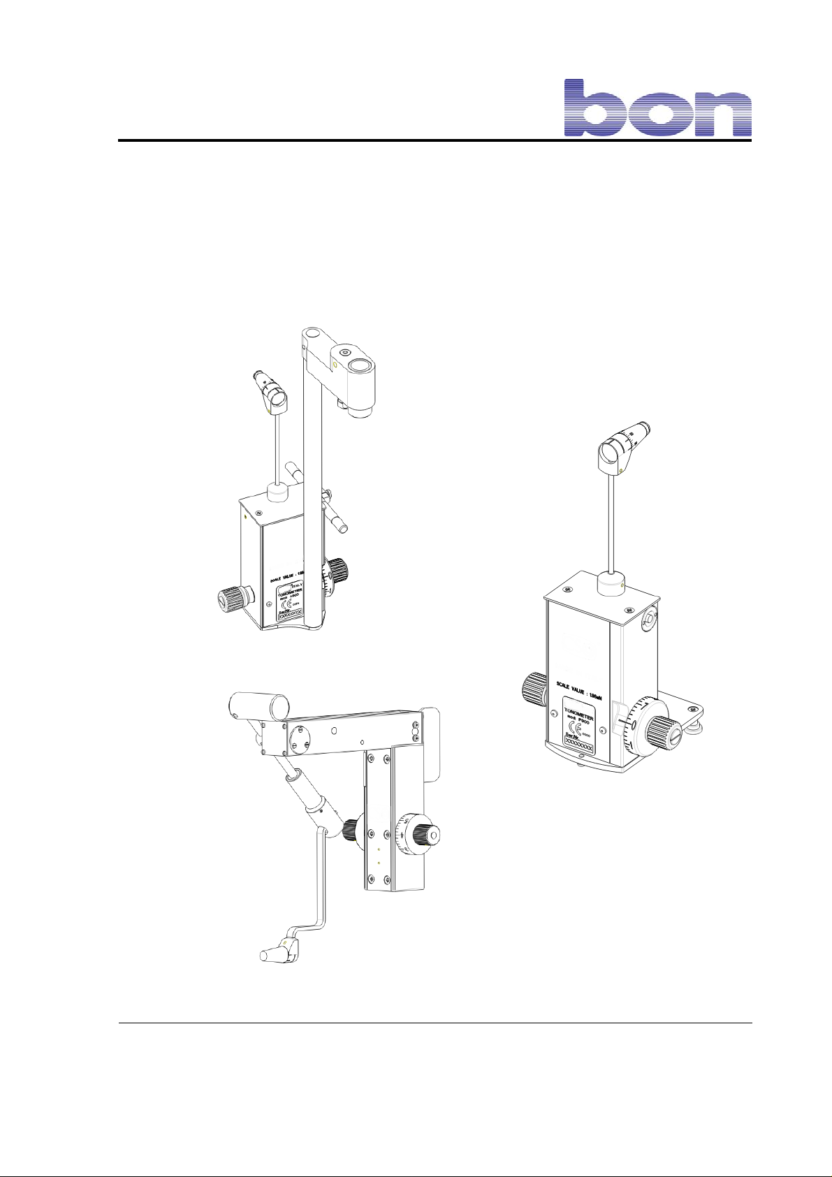
Applanation Tonometer
-900
T-900
Z-800
GA bon T900_A900_Z800 Rev 1.2 E 09.02.09.doc
PO Box 32 26
23581 Lübeck
Stellmacherstraße 14
D-23556 Lübeck
bon Optic Vertriebsgesellschaft mbH – managing director: H. Jochen Kaber – HR Lübeck, HRB 3475 – VAT No. 161662634
Phone: 0451/ 80 900-0
Fax: 0451/ 80 900-10
E-Mail: [email protected]
Internet: www.bon.de
Sparkasse zu Lübeck
(Sort code 230 501 01) Acc.No. 1 014 885
Swift / BIC: HSHN DE H1 SPL
IBAN: DE 2305 0101 0001 0148 85
Commerzbank Lübeck
(Sort code 230 400 22) Acc.No. 0 107 755
Postbank Hamburg
(Sort code 200 100 20) Acc.No. 409 22-204
Page 2

DS 2/20
Page 3

Contents
1 Introduction.....................................................................................................4
2 Important Information.....................................................................................5
2.1 System Information ............................................................................................ 5
2.2 Application and classification ............................................................................. 5
2.3 Liability ............................................................................................................... 5
2.4 Scope of delivery................................................................................................6
3 Safety Instructions..........................................................................................7
4 Assembly.........................................................................................................8
5 Functional Principle........................................................................................9
6 Accomplishment of a Pressure Measurement............................................10
6.1 Preparation of Slit Lamp and Applanation Tonometer ..................................... 10
6.2 Preparation of the Patient................................................................................. 10
6.3 Pressure Measurement Procedure .................................................................. 10
7 Failure Sources .............................................................................................12
8 Informations regarding the Examination ....................................................13
8.1 General............................................................................................................. 13
8.2 Measurements involving Astigmatism.............................................................. 13
9 Controlling the Measurement Display.........................................................14
9.1 T-900, A-900 .................................................................................................... 14
9.2 Z-800................................................................................................................ 15
10 Maintenance and Care..................................................................................17
10.1 Care..............................................................................................................17
10.2 Maintenance................................................................................................. 17
10.3 Measuremental Technical Control (MTK)..................................................... 17
11 Guarantee ......................................................................................................18
12 Technical Data...............................................................................................19
Appendix: EC-Declaration of Conformity
3/20
Page 4

1 Introduction T-900 / A-900 / Z-800
1 Introduction
Dear customer
Thank you for choosing one of our applanation tonometers. Please read the operating
instructions carefully before using the device. Keep this instruction manual safe for future
use.
Please observe the safety instructions.
If you have any further questions, please contact our customer helpline.
Meaning of the symbols in the operating instructions
Caution! Please observe safety instructions with this symbol to prevent
personal danger or damage to property.
Important! Indicates particularly important information to maintain the
function of the device/system or to extend its life.
This publication may not be copied or transferred without prior agreement from bon Optic.
bon Optic reserves the right to make changes in the interest of technical development. These operating
instructions are not subject to updating.
Note! Indicates information for correct use so that errors may be avoided.
4/20
Page 5

2 Important Information T-900 / A-900 / Z-800
2 Important Information
Manufacturer : bon Optic Vertriebsgesellschaft mbH · Stellmacherstr. 14 · D-23556 Lübeck
2.1 System Information
Device name : T-900 / A-900 / Z-800
2.2 Application and classification
The applanation tonometer is used for the measurement of the intraocular pressure of the
eye and may only be operated by competent and accordingly briefed persons. The apparatus
is operated in combination with a slit lamp.
The applanation tonometer T-900 / A-900 / Z-800 is a Class 1 non-invasive, active medical
device in accordance with the classification regulations of Directive 93/42/EWG on medical
devices (MDD).
2.3 Liability
The applanation tonometer is manufactured according to the current technical status and the
recognized safety regulations and is tested in accordance with strict quality criteria.
bon Optic only accepts liability for the safety, reliability and performance of the device if
assembly, changes or repairs have been carried out by a person by competent
persons.
the device is operated in accordance with these operating instructions.
the operator complies to the Ordinance on the Operation of Medical Devices
(MPBetreibV).
If the system is assembled, changed or repaired by an unauthorized person, if it is improperly
maintained or not used as described in 2.2, the manufacturer is no longer liable.
5/20
Page 6

2 Important Information T-900 / A-900 / Z-800
2.4 Scope of delivery
T-900:
1 x Applanation Tonometer T-900
1 x Gauging Prism
1 x Retaining Plate
1 x Check Weight
1 x Allen Key
1 x Instruction manual
A-900:
1 x Applanation Tonometer A-900
1 x Gauging Prism
1 x Retainer
1 x Check Weight
1 x Allen Key
1 x Instruction manual
Z-800:
1 x Applanation Tonometer Z-800
1 x Gauging Prism
1 x Retainer
1 x Check Weight
1 x Allen Key
1 x Instruction manual
6/20
Page 7

3 Safety Instructions T-900 / A-900 / Z-800
3 Safety Instructions
Please follow the legal requirements on accident prevention and observe the following safety
instructions!
Setting-up and assembly:
After receiving the device, leave it in the original packing, in order to ensure that the
components reach ambient temperature and therefore prevent possible
condensation.
Operating:
Do not expose the device to extreme temperatures.
Avoid dropping or splashing water on the device.
The operating temperature is between +15° C and +30° C.
Marginal values for barometric pressure: >=700hPa und <=1060hPa
Marginal values for relative humidity: >=30% und <=75%
Check the gauging prism for damages before every use, by the use of the slit lamp
microscope for example.
In the case of a cracking, disinfectant may infiltrate into the antrum of the gauging
prism. If it comes into contact with the patient’s eye, this may result in a chemical
burn of the cornea.
Other Information:
Take notice of the cleaning information.
Take notice of the relevant national regulations regarding the measuremental
technical control.
Avoid any shock or impact and do not expose the device to permanent vibrations.
7/20
Page 8
4 Assembly T-900 / A-900 / Z-800
4 Assembly
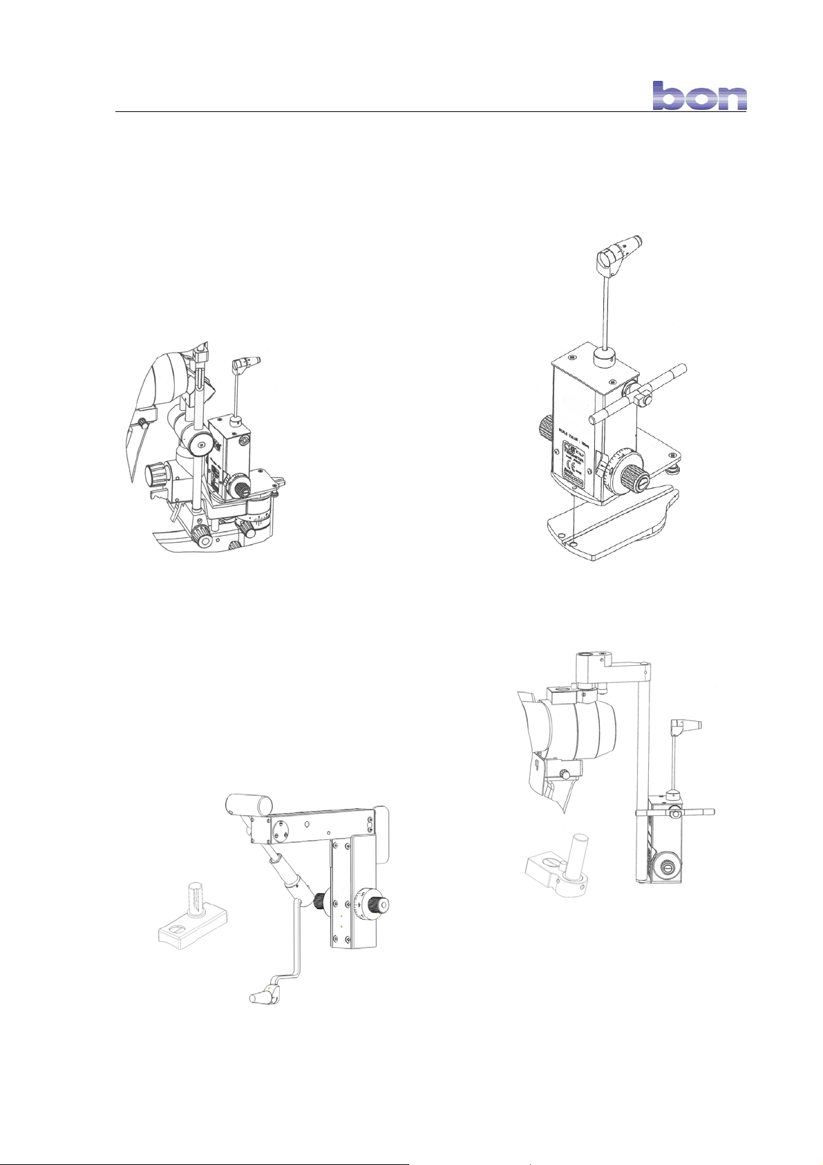
T-900:
Stick the pictured retaining plate into the slit lamp axis,
using the connected pin.
If necessary, take of the cap on the axis.
Then place the applanation tonometer
on the retainer plate.
A-900 / Z-800:
Screw the pictured retainer onto the magnification
adjuster of the slit lamp. If necessary, remove the cap of
the threaded hole. Then apply the applanation tonometer
to the pin on the retainer.
8/20
Page 9

5 Functional Principle T-900 / A-900 / Z-800
5 Functional Principle
The applanation tonometer defines the intraocular pressure, by measuring the force required
to flatten a defined surface of the cornea.
The cornea is applanated by a plexi-glas pressure-corpus, which is set in a ring-shaped
retainer at the end of the pressure arm. The circular pressure surface has a diameter of 7,0
mm and is flat, featuring a rounded edge, whereby an injury of the cornea is made
impossible.
The pressure corpus is brought into contact with the patient’s eye by mowing the slit lamp
forward. Then the pressure corpus is pushed onto the eye with increasing force, until an area
with a diameter of 3.06 mm (this equals a circular area of 7,35 mm
The user accomplishes the precise optical measurement of the small flattening surface
visualy, by using a factor 10 magnification on the slit lamp.
In the area of surface contact between cornea and pressure corpus the tear fluid is forced
outward. It contains flouresceine and shines green-yellow because of the blue light. The
boundary between flattened and curved cornea appears clearly as a fine green-yellow band.
The built-in doubling system within the pressure corpus splits the picture of the flattened
circle and displaces the two halves by 3,06 mm to each other.
The rigidity of the cornea and the eye-ball (bulbus) is inconsiderable, due to the fact that the
small area of flattening, of only 7,35mm², the shift in volume only amounts to a mere 0,56
mm³. The intraocular pressure is only raised by approximately 2,5% through the measuring
process. Repeated measurements do not decrease the intraocular pressure, because a
massage-effect does not occur due to the low pressure increase.
The measured data is displayed directly in mmHg. All versions have high accuracy. The error
of a single measurement averages at approximately ± 0,5 mmHg.
2
) is flattened.
9/20
Page 10

6 Accomplishment of a Pressure Measurement T-900 / A-900 / Z-800
6 Accomplishment of a Pressure Measurement
6.1 Preparation of Slit Lamp and Applanation Tonometer
Make sure that the applanation tonometer is properly mounted to the slot lamp.
The measuring prism must be disinfected.
Do not use alcoholic solutions for disinfections!
Place the blue filter into the lighting-ray channel of the slot lamp.
Place the green filter observation-ray channel in order to monitor the green
fluorescence light.
Turn the pressure head with the gauging prism towards the patient until it snaps in
place.
Turn the measuring drum to the scale line 1.
Note: If the cornea is touched without
vibration.
pressure, the patient feels an unpleasant
6.2 Preparation of the Patient
Use an appropriate anesthetic to numb the surface of the eye.
Optionally use a liquid fluorescine or in form of paperstrips, for the precise
observation of the eye-surface.
Let the patient place his chin onto the chinrest and make sure that his forehead
touches the brow-band.
6.3 Pressure Measurement Procedure
Ask your patient to look straight.
Bring the gauging prism to eye level, using the slit lamp.
If fluoresceine was used, the patient should shortly close his eyes directly before the
measurement. This way the cornea is sufficiently moistened with tear fluid.
Slowly move the slit lamp forward, in order to bring the gauging prism into contact
with the cornea (central – in the area of the pupil). When contact is made, the
boundary of the cornea (limbus) shines bluish. This shining is best observed from the
side (not through slit lamp microscope). Immediately stop the forward movement of
the slit lamp, after contact with the cornea is established.
10/20
Page 11

6 Accomplishment of a Pressure Measurement T-900 / A-900 / Z-800
Now look through the microscope of the slit lamp. If the two semicircular fluoresceine
bands pulsate at a constant pace, the applanation tonometer is in the correct
measuring position (diagr. 6.1). The fluoresceine bands may be of differing size,
depending on the intraocular pressure. If necessary, correct the position of the
applanation tonometer with the joystick of the slit lamp until you can see following
picture in the observation field:
Diagram 6.1
Marginal movements of the slit lamp do not influence the size of the semi circles.
Now, increase the pressure by turning the measuring drum, until the inner edges of
the semi circles slightly touch each other. They should overlap at eye-pulsation:
Diagram 6.2
The width of the fluoresceine band should amount approximately 1/10 of the diameter of the
flattened surface, thus approx. 0,3 mm.
The scale reading on the measuring drum multiplied by 10 equals the intraocular pressure
in mmHg.
The use pressure measurement in mmHg in medicine has historical reasons (pressure
measurement by utilizing a mercury column).
This equals:
1 mmHg = 0,00133 bar
1 bar = 750 mmHg
11/20
Page 12
7 Failure Sources T-900 / A-900 / Z-800
7 Failure Sources
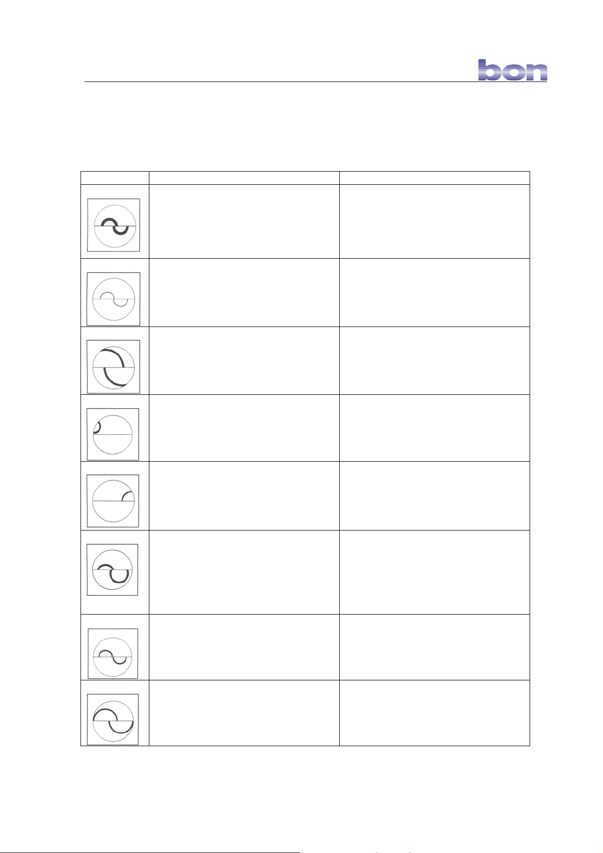
The following shows up typical errors and/or maladjustments and how to avoid them.
Diagram Cause Solution
Fluoresceine band too wide:
The gauging prism was not dried properly
after cleaning, or the eyelid came in contact
with the gauging prism during the
measurement. The reading will be higher
than the true intraocular pressure.
Fluoresceine band too narrow:
The tear fluid dried out during the longer
measurement. The reading will be lower
than the true intraocular pressure.
Fluoresceine band too big:
a) The gauging prism is not touching the
cornea correctly.
b) The protection weight is squeezing the
eye. The flattened area is too big.
The two semi-circular surfaces are not
positioned in the middle of the pupil
area:
The position of the gauging prism is not
correct.
The two semi-circular surfaces are not
positioned in the middle of the pupil
area:
The position of the gauging prism is not
correct.
The two semi-circular surfaces are not
positioned in the middle of the pupil
area:
The position of the gauging prism is not
correct and the pressure is too high. The
pressure reading here is significantly higher
than the true intraocular pressure.
The inner edges of the fluoresceine
bands do not touch each other:
The measuring pressure is too low.
Abort the measurement and dry-off the
gauging prism.
Abort the measurement and let the patient
close his eyes a few times in order to
produce tear liquid.
Retract the slit lamp and re-apply the
gauging prism until you can observe an
even pulsation.
Lift the slit lamp and move it to the left.
Move the slit lamp to the right.
Lower the slit lamp and decrease the
pressure put onto the eye by the gauging
prism.
Increase the pressure with the measuring
drum.
The inner edges of the fluoresceine
bands do not touch each other:
The measuring pressure is too high.
Decrease the pressure with the measuring
drum.
12/20
Page 13

8 Informations regarding the Examination T-900 / A-900 / Z-800
8 Informations regarding the Examination
8.1 General
Patients that are upset and/or frightened, usually have a higher intraocular pressure at the
first measurement. Therefore a decrease of tension occurs within the first minute, because
the patient realizes, that tonometry with the applanation tonometer is not connected to
unpleasant sensations. At good anesthesia and well-opened eyes, the patient feels
absolutely nothing. Therefore accomplish a test measurement on both eyes, of which you
discard the results. Following that, three more measurements are achieved on each eye. The
measured results are correct, when the pressure has stabilized. If the procedure is followed
correctly, the variance between the results is ± 0,5 mmHg.
At long lasting measurement on one eye, more or less obvious signs dehydration of the
corneapithel on both eyes occurs. A ring of small fluoresceine-positive dots appears on the
contact area between the cornea and the pressure corpus of the eye, which is measured at
the moment. Irregular „maplike“ fluoresceine-positive spots occur on the other eye, making a
relevant measurement impossible.
Due to this fact only short but alternating measurements on both eyes should be
accomplished. Obviously the visual acuity is influenced by these fine epithel defects.
Therefore examinations regarding visual acuity and visual field should be accomplished
before the tonometry.
8.2 Measurements involving Astigmatism
If the cornea is spherical, the examination can be done on any given meridian, most
comfortably on the 0°-Meridian. On eyes with an astigmatism greater than 3 diopters, the
chosen meridian is of greater importance, because the flattened surface is not circular
anymore, but elliptic. Calculations show that at greater cornea-astigmatisms an area of 7,354
2
mm
(diameter 3,06 mm) is flattened, when the pressure corpus is positioned in an angle of
43° to the meridian of the greatest radius.
For Example:
If the astigmatism of the cornea is 6.5 mm/ 30° = 52.0 dpt/30° and
8.5 mm/120° = 40.0 dpt/120°
the 120°-mark of the scaling on the pressure corpus is set to the red 43°-mark on the prism
retainer.
If on the other hand the following is measured 8.5 mm/ 30° = 40.0 dpt/30° und
6.5 mm/120° = 52.0 dpt/120°
the scale interval 30° is set to the red 43°-mark.
The axis angle of the greatest radius is simply set to the red 43°-mark here.
13/20
Page 14
9 Controlling the Measurement Display T-900 / A-900 / Z-800
9 Controlling the Measurement Display
The pressing force of the pressure corpus is caused by a spring in the device. Because this
can change through inappropriate use, but also through aging, the device should be checked
on a regular basis. The check is accomplished in 3 drum positions:
9.1 T-900, A-900
a) Check at Drum Position 0
Insert the gauging prism.
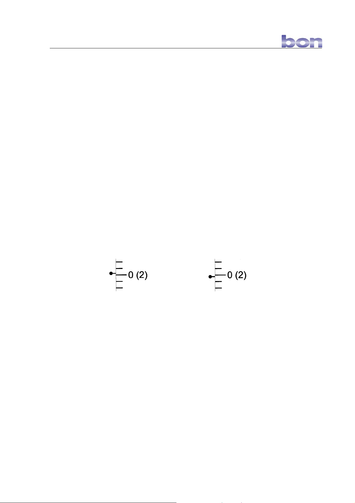
Check-Position - 0.05:
Move the zero-mark of the measuring drum downward against the index, for the width of the
mark (diagr. 9.1). If the pressure arm is brought into the area of free movement between the
catches, it should autonomously move against the catch toward the examiner.
Check-Position + 0.05:
Move the zero-mark of the measuring drum upward against the index, for the width of the
mark (diagr. 9.2). Analogical the pressure arm should move towards the catch on the
patient’s side.
Diagram 9-1 Diagram 9-2
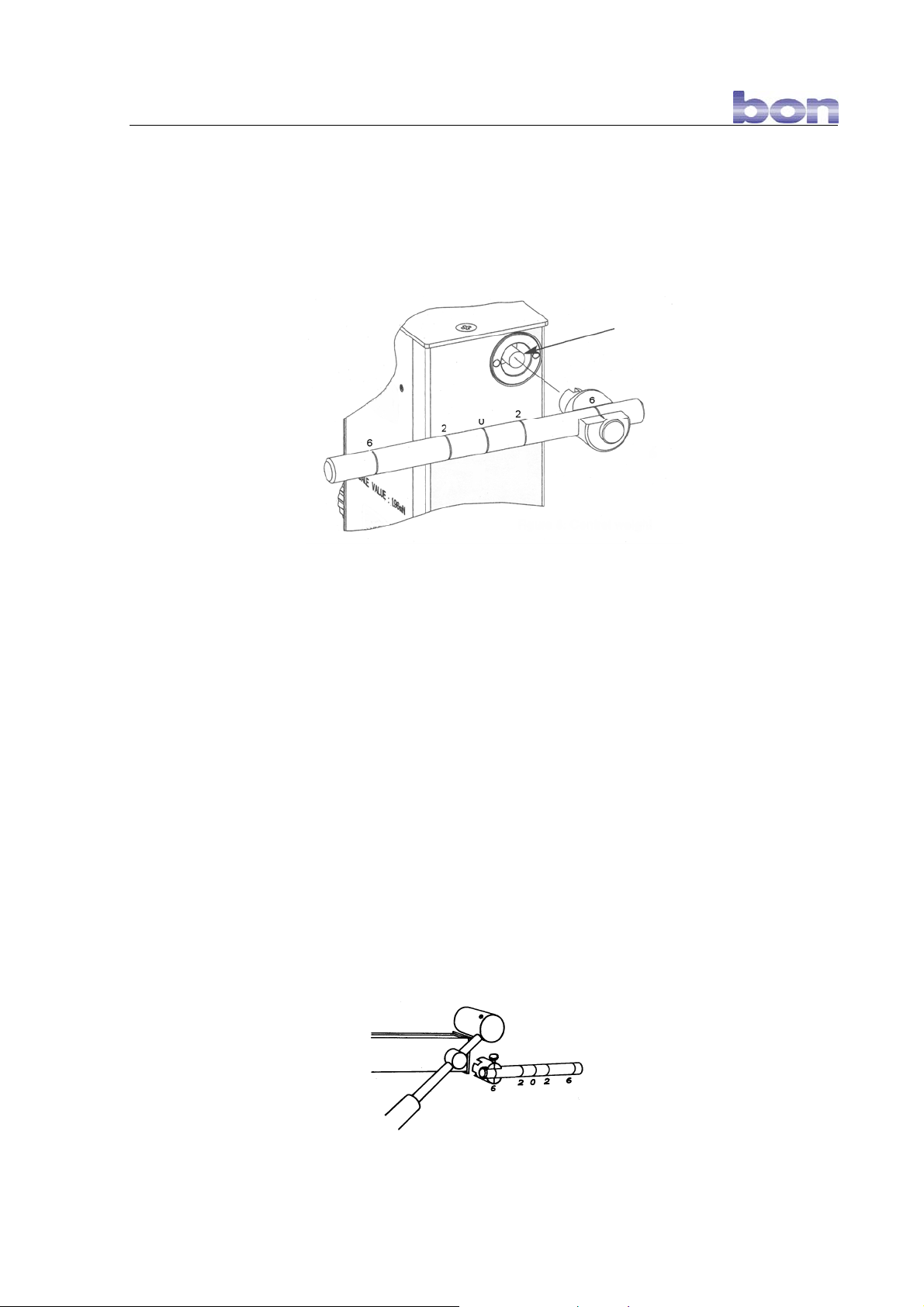
b) Check at Drum Position 2
Herefore use the included check-weight, which has 5 engraved rings.
The ring in the middle equals the scale value 0, the two rings immediately left and right of it
equal the scale value 2 and the two most outbound equal the scale value 6.
Now, adjust to the scale value 2, using the index mark on the retainer of the check weight, so
that the longer part is showing towards the examiner. Insert the check weight into the
sensing axis (see analog diagr. 9.3).
The pressure arm now must move, at drum position 1.95 / 2.05, out of the area of free
movement to the appropriate catch. The check at scale value 2 is the most important,
because the measurement of the intraocular pressure in this area has the most significant
importance.
14/20
Page 15
9 Controlling the Measurement Display T-900 / A-900 / Z-800
c) Check at Drum Position 6
Analogical the tonometer may be checked at scale value 6. The check values then are at
5.9 / 6.1. Move the scale mark on the measuring drum up or down against the index for 1/2
interval.
Sensing axis
Diagram 9.3
9.2 Z-800
a) Check at Drum Position 0
Insert the gauging prism and set the measuring drum on the tonometer to scale value 0. The
arm with the gauging prism should now swing freely between the catches.
b) Check at Drum Position 2
Herefore use the included check-weight, which has 5 engraved rings.
The ring in the middle equals the scale value 0, the two rings immediately left and right of it
equal the scale value 2 and the two most outbound equal the scale value 6.
Now, adjust to the scale value 2, using the index mark on the retainer of the check weight, so
that the shorter part is showing towards the examiner. Insert the check weight into the
sensing axis (see analog diagr. 9.4).
Diagram 9.4
15/20
Page 16

9 Controlling the Measurement Display T-900 / A-900 / Z-800
Check-Position - 0.05:
Move the zero-mark of the measuring drum downward against the index, for the width of the
mark (diagr. 9.5). If the pressure arm is brought into the area of free movement between the
catches, it should autonomously move against the catch toward the examiner.
Check-Position + 0.05:
Move the zero-mark of the measuring drum upward against the index, for the width of the
mark (diagr. 9.6). Analogical the pressure arm should move towards the catch on the
patient’s side.
2
2
Diagram 9.5 Diagram 9.6
c) Check at Drum Position 6
Analogical the tonometer may be checked at scale value 6. The check values then are at
5.9 / 6.1. Move the scale mark on the measuring drum up or down against the index for 1/2
interval.
16/20
Page 17

10 Maintenance and Care T-900 / A-900 / Z-800
10 Maintenance and Care
10.1 Care
Clean the applanation tonometer with a clean and damp leather cloth. Do not use any
scrubbing or aggressive cleaning aids!
Use an appropriate disinfectant for the gauging prism (Sekusept
- for example) and take note of the instruction manual.
Standard Disinfections of Gauging Prisms:
1. Clean the gauging prism under running cold water for 30-60 seconds.
2. Disinfect the gauging prism in accordance to the instruction manual of the disinfectant
(Pantasept
3. Rinse the gauging prism (min. 10 - max. 60 min.) under running cold water.
4. Dry the gauging prism with a clean and soft cloth.
5. Store the gauging prism in a clean and dry container.
®
- 10 minutes, 3 % aqueous solution, for example).
®
, Gigasept® FF, Pantasept®
10.2 Maintenance
Control the measurement display in 6-month intervals (see chapter 9).
Change the reusable gauging prism every 2 years at the latest, in order to provide optimum
safety to your patients.
10.3 Measuremental Technical Control (MTK)
This device is subject to a, required by law, Measuremental Technical Control by an
authorized test center (in 2 year intervals in Germany).
17/20
Page 18

11 Guarantee T-900 / A-900 / Z-800
11 Guarantee
Should defects as the result of material or production errors occur within 24 months of
purchase, we guarantee free-of-charge repair of the appanation tonometer or we will decide
whether to offer you a free exchange, provided that:
A receipt with the date of purchase can be provided.
The device has been used properly and in accordance with the conditions of use.
Repairs have not been carried out by anyone other than the bon Optic customer
service team or persons authorized by bon Optic.
Guarantee services do not result in extension of the guarantee, nor do they represent the
start of a new guarantee. The sales guarantee is not applicable to consumable products.
The terms and conditions of trade of bon Optic also apply.
18/20
Page 19
12 Technical Data T-900 / A-900 / Z-800
12 Technical Data
Measuring Method: Spring-loaded Weight
Measuring Range: 0 – 80 mmHg (0 – 10.64 kPo)
Backlash: < 0.25 mN
Standard Deviation: 0.49 mN 3s 1.5% (measured value)
Operational Temperature: 15° - 30°C
Limit Values Ambient Pressure: >=700hPa and <=1060hPa
Limit Values Relative Humidity: >=30% und <=75%
Net weight A-900: 0.73 kg (without accessories)
Net weight T-900: 0.65 kg (without accessories)
Net weight Z-800: 0.85 kg (without accessories)
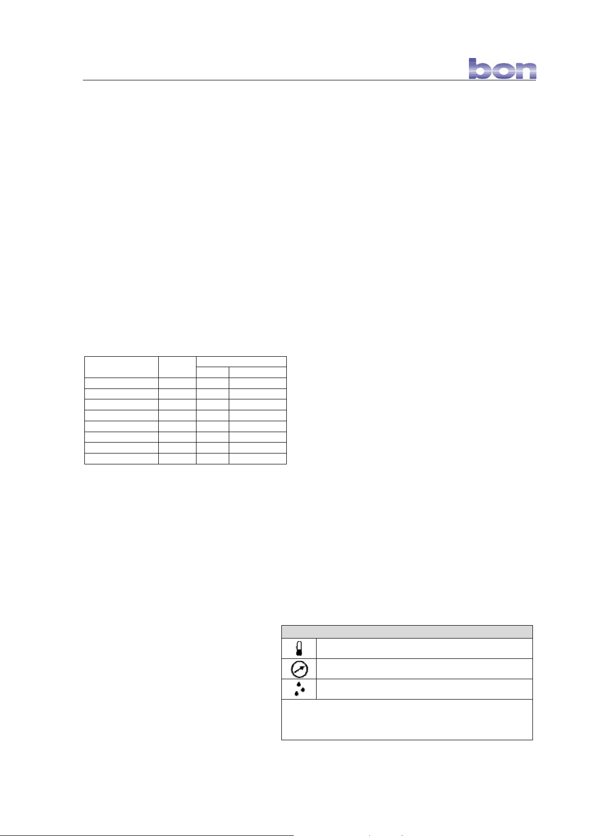
Correlation between the Setting of the Measuring Drum, Force and Pressure:
Pressure Position of the
kPa mmHg
Transport und Storage Instructions
Temperature: -10 °C to +60 °C (+14 °F to+140 °F)
Barometric Pressure: 500 hPa to 1060 hPa
Relative Humidity: 10% to 90%
Do not maintain the Maximum Conditions for more than 15
consecutive weeks!
Meas. Drum
1 9,81 1,33 10
2 19,62 2,66 20
3 29,43 3,99 30
4 39,24 5,32 40
5 49,05 6,65 50
6 58,86 7,98 60
7 68,67 9,31 70
8 78,48 10,64 80
Force/
mN
19/20
Page 20

Appendix T-900 / A-900 / Z-800
Hersteller-Adresse:
(Manufacturer adress)
Gerätetyp / UMDNS-CODE:
(Device typ/ UMDNS-CODE)
Gerätebezeichnung:
(Device name)
Klassifizierung:
(Classification)
Wir erklären hiermit die Übereinstimmung des vorgenannten Produkts mit der
EU-Richtlinie 93/42/EWG über Medizinprodukte.
We declare the compliance of the device with the requirements of the Derective
93/42/EEC about medical devices.
EU - KONFORMITÄTSERKLÄRUNG
EC – DECLARATION OF CONFORMITY
bon
Optic Vertriebsgesellschaft mbH
Stellmacherstraße 14
D-23556 Lübeck
Applanationstonometer / (10-168)
Applanation tonometer / (10-168)
T-900 / A-900 / Z-800
1 (Richtlinie 93/42/EWG, Anhang IX, Regel 1)
1 (MDD 93/42/EEC, annex IX, rule 1)
Angewandete Normen:
(Applicable standards)
Überwachungsbehörde/ ID-Nr.:
(Notified body/ Identification number)
Das Gerät ist gekennzeichnet mit / The device is marked with
(Das CE-Zeichen bestätigt die Übereinstimmung des Applanationstonometers mit der EU-Richtlinie 93/42/EWG einschl. I,VI,VII)
(The CE marking confirms the compliance of the Applanation Tonometer with directive 93/42/EEC enclose I, VI, VII)
Lübeck, den 01. Juni 2004
(H. Jochen Kaber, Geschäftsführer)
DIN EN 60601-1 (03/96)
EN 46000
ISO 8612
IMQ / 0051
0051
20/20
 Loading...