

Page 1
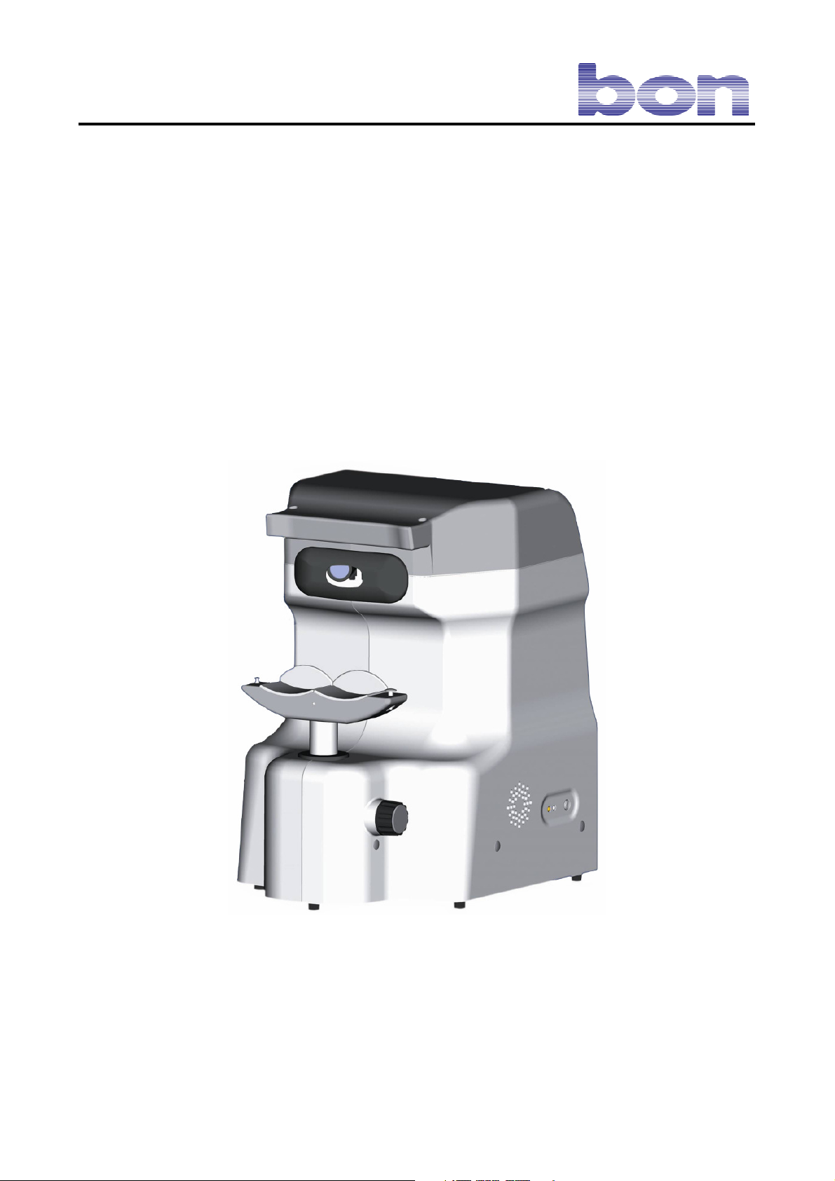
Specular Microscope EM-2
Instructions for Use and Maintenance
Page 2

GA Endothelmikroskop EM-2 Rev 0.3 220910 E.doc
PO Box 32 26
23581 Lübeck
Stellmacherstraße 14
D-23556 Lübeck
bon Optic Vertriebsgesellschaft mbH – Managing Director: H. Jochen Kaber – HR Lübeck, HRB 3475 – VAT No. 161662634
Phone: 0451/ 80 900-0
Fax: 0451/ 80 900-10
E-Mail: [email protected]
Internet: www.bon.de
Sparkasse zu Lübeck
(Sort code 230 501 01) Acc.No. 1 014 885
Swift / BIC: NOLADE21SPL
IBAN: DE 2305 0101 0001 0148 85
Commerzbank Lübeck
(Sort code 230 400 22) Acc.No. 0 107 755
Postbank Hamburg
(Sort code 200 100 20) Acc.No. 409 22-204
Page 1 of 45
Page 3

CONTENTS
1. INTRODUCTION .......................................................................................................................................................... 4
2. GENERAL SAFETY PRECAUTIONS ........................................................................................................................ 4
3. BRIEF DESCRIPTION OF THE INSTRUMENT – USES........................................................................................ 5
3.1. ACCESSORIES......................................................................................................................................................... 6
4. OPERATING CONDITIONS ....................................................................................................................................... 6
5. END-OF-LIFE DISPOSAL ENVIRONMENTAL CONSIDERATION ................................................................... 7
6. LEGEND .........................................................................................................................................................................8
7. INSTALLATION............................................................................................................................................................ 9
7.1. UNPACKAGE THE INSTRUMENT AND REASSEMBLING THE OPTICAL HEAD (23) ................................ 9
7.2. CONNECTING THE INSTRUMENT ......................................................................................................................9
7.3. PRECAUTIONS ........................................................................................................................................................9
8. INSTRUCTIONS FOR USE ........................................................................................................................................ 11
8.1. LAUNCHING THE SOFTWARE ..........................................................................................................................11
8.2. THE MAIN WINDOW ........................................................................................................................................... 11
8.3. TOOLBAR BUTTONS SUMMARY...................................................................................................................... 12
8.4. SETTINGS ..............................................................................................................................................................12
8.4.1 LANGUAGE 12
8.4.2 GROUPS 13
8.4.3 MISCELLANEOUS 13
8.4.4 DICOM 14
8.5. Patient Management ................................................................................................................................................ 14
8.5.1 CREATING A NEW PATIENT 14
8.5.2 CREATING A NEW EXAMINATION 14
8.6 CAPTURE ................................................................................................................................................................15
8.6.1 CAPTURE WINDOW COMMANDS 15
8.7 ANONYMOUS CAPTURE .....................................................................................................................................17
8.8 CAPTURING CORNEAS WITH DIFFERENT THICKNESSES...........................................................................18
8.8.1 EXAMPLES 18
8.9 REMOTE CONTROL .............................................................................................................................................. 20
8.10 THE REMOTE CONTROL KEY FUNCTIONS ...................................................................................................20
8.11 USING THE REMOTE CONTROL FOR IMAGE CAPTURE.............................................................................21
8.11.1 EXAMPLES 22
8.12 AUTOMATIC CELL COUNT ...............................................................................................................................24
8.12.1 TOOLBAR BUTTONS AT THE TOP OF THE SCREEN 25
8.12.2 EDITING SELECTED CELLS 26
8.13 DELETING CELLS ............................................................................................................................................... 26
8.14 EDITING IMAGE PARAMETERS .......................................................................................................................27
8.15 PROCESSING ........................................................................................................................................................28
8.16 ANALYSIS RESULTS ..........................................................................................................................................29
8.17 COMPARISON ......................................................................................................................................................30
8.18 OVERALL COMPARISON OF ALL THE CORNEAL AREAS (Multifix).........................................................31
8.19 OPENING A PATIENT FILE IN THE ARCHIVE ............................................................................................... 32
8.20 ADVANCED SEARCH .........................................................................................................................................32
8.21 PATIENT MENU OPTIONS ................................................................................................................................. 33
8.22 EXAMINATIONS MENU OPTIONS ................................................................................................................... 33
8.23 IMAGES MENU OPTIONS .................................................................................................................................. 33
8.24 PRINTING.............................................................................................................................................................. 34
8.25 DICOM ................................................................................................................................................................... 35
Page 2 of 45
Page 4

9. OPERATING FEATURES .......................................................................................................................................... 37
10 ROUTINE MAINTENANCE ..................................................................................................................................... 38
10.1 REPLACING THE LINE FUSES .......................................................................................................................... 38
10.2 REPLACING THE MONITOR FUSE................................................................................................................... 38
10.3 REPLACING THE HALOGEN (28) AND/OR FLASH (27) LAMP .................................................................... 38
10.4 PROTECTING THE INSTRUMENT FROM DUST.............................................................................................39
11. TECHNICAL DESCRIPTION.................................................................................................................................. 40
11.1 CLASSIFICATION ACCORDING TO EN 60601 STANDARD ......................................................................... 40
11.2 FUNCTION BLOCK DIAGRAM..........................................................................................................................41
11.3 DATA PLATE SYMBOLS ....................................................................................................................................42
12. LIABILITY ................................................................................................................................................................. 43
13. WARRANTY AND TECHNICAL ASSISTANCE.................................................................................................. 43
14. CERTIFICATES / STATEMENTS OF COMPLIANCE ....................................................................................... 44
15. REFERENCE STANDARDS .................................................................................................................................... 45
Page 3 of 45
Page 5
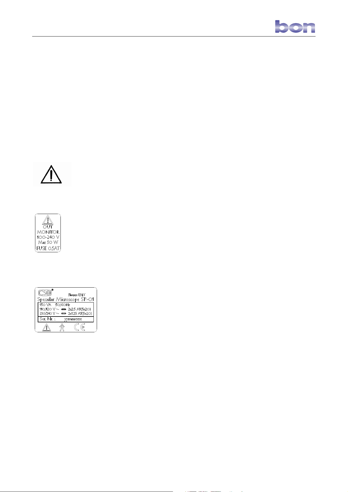
Monitor Socket Data Plate
Instrument Data Plate
11.. IINNTTRROODDUUCCTTIIOONN
Thank you for having purchased EM-2 by bon Optic
All bon Optic products are manufactured to rigorous safety standards. In
particular, the SP 01 specular microscope is a high-performance instrument. In
order to use it efficiently and in complete safety we recommend reading this
manual carefully before beginning installation and heeding all the safety
warnings provided herein and on the instrument labels. Even technicians who
have already used this type of instrument should verify their knowledge of the
instructions contained in this manual. Keep this manual near the instrument
for handy reference during use
22.. GGEENNEERRAALL SSAAFFEETTYY PPRREECCAAUUTTIIOONNS
-
Check that your line voltage is the same as that reported on the instrument
data plate. Should the values differ, contact your customer service or the
manufacturer (see INSTALLATION section). Your electrical system must
comply with CEI/IEC standards for electrical systems for medical use. In
case of doubt, contact your installation and maintenance service.
-
Never use multiple plugs, adapters, or extension cords to connect the
instrument plug to the line socket.
-
When unplugging the instrument from line power supply, even under
emergency conditions, grasp the plug and never the cord; never pull the
cord to disconnect the plug.
-
Never touch the power cord with wet hands. Check frequently that the cord
is so placed as not to be stepped on or crushed by weights. Never knot the
cord.
-
A damaged power cord can cause fires or electrical shocks. Check
frequently that the instrument power cord is in good condition. If it becomes
necessary to replace the power cord originally supplied with the instrument,
contact your supplier.
-
Do not perform any repairs or maintenance work on the instrument or the
electrical system beyond what is explained in this manual.
-
Do not use the instrument near water and be careful not to spill liquids on
any part of it. Avoid damp and dusty locations and locations subject to
brusque changes in temperature and humidity.
-
Disconnect the instrument from the line power supply before cleaning
and/or disinfecting.
-
The instrument neither generates nor receives electromagnetic
interference when used in proximity to other devices; no preventive or
corrective measures need therefore be taken.
-
The standard version instrument contains non-medical accessories
(LCD monitor, keyboard, and mouse). The resulting system is tested
in accordance with international standards EN 60601-1 “Medical
Electrical Equipment. PART 1: General Requirements for Safety” and
EN 60601-1-1 “Collateral Standard: Safety Requirements for Medical
Electrical Systems” and is fully compliant with these standards. Note
that the standard version instrument can be connected to other
S
Page 4 of 45
Page 6
instruments, medical electrical and not; bon Optic cannot test the
compliance of all possible system configurations
-
Any additional accessories (printer, scanner, CD reader, etc..)
connected to the analog or digital interfaces must be certified in
accordance with the standards listed below:
For the United States of America:
UL 1950 for ITE devices.
UL 2601-1 for medical electrical devices.
For Europe:
EN 60950 for ITE devices.
EN 60601-1 for medical electrical devices;
-
Once all the equipment making up the system has been connected
and assembled, check that the resulting medical electrical system
complies to the requirements set by EN 60601-1-1 “Collateral
Standard: Safety Requirements for Medical Electrical Systems.”
-
Should the leakage current values exceed the limits set by standard
EN 60601-1-1, additional safety measures must be adopted as
suggested by the standard itself. In this case, we recommend
powering the entire system through a safety insulating transformer.
33.. BBRRIIEEFF DDEESSCCRRIIPPTTIIOONN OOFF TTHHEE IINNSSTTRRUUMMEENNTT ––
UUSSEESS
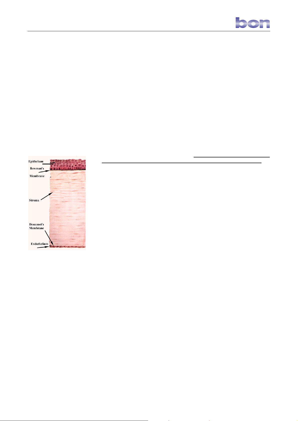
The endothelium is the deep layer of the cornea, in a young subject about 5
micrometers in thickness and possessing about 300,000 hexagonal cells.
The endothelium is important for correct corneal function; for this reason,
analysis of the endothelium is of fundamental importance for diagnosis of the
health of the eye.
The most important characteristic of endothelial cells is their lack of reproductive
capacity; age, surgical treatment, and use of contact lenses are factor
influencing their quantity and form.
As already mentioned, the cells composing the endothelium, which are
hexagonal in children and younger people, do not reproduce and their form and
quantity influence the health of the cornea. At birth, the endothelium contains
about 4000 cells/mm2; with time, the number decreases and the structure of the
layer accordingly changes.
The bon Optic specular microscope permits obtaining electronic photographs of
the patient’s endothelium with no instrument contact with the patient. The
acquired endothelium image can then be mathematically processed to display
clinically-useful endothelial parameters relative to the cells, including: cell
number and density, form, surface area, mean area, standard deviation,
coefficient of variation, percentage of cells of different forms, histogram of cell
area distribution, pachimetric datum.
The bon Optic specular microscope permits performing:
• Non-invasive examination of the endothelial tissue.
• Automatic focusing of the endothelial layer of the cornea.
Automatic search for cell borders and broad-based statistical analysis of the
data.
The bon Optic specular microscope is an indispensable aid in diagnosing
corneal health.
Page 5 of 45
Page 7

It is extremely useful in pre- and post-transplant examinations, after cataract
surgery, and for analysis of trauma damage to the cornea.
Since the examinations performed with the bon Optic specular microscope are
totally non-invasive with no patient contact,:
• there is no risk of transmission of infectious diseases.
• the examination is absolutely painless and does not require use of any
local anesthetics.
The instrument is composed of:
the SPECULAR MICROSCOPE as such, designed and built by bon Optic, and
the user accessories listed below:
1. 15.1” LCD monitor (50 W max. power requirement);
2. Keyboard;
3. Mouse.
AUXILIARY and ACCESSORY DEVICES:
4. Commercially-available ink jet color printer compliant with
international standard EN 60950.
5. 230V-230V insulating transformer (leakage current limiter)
for use in operating rooms, compliant with international
safety standard EN 60742.
6. Wooden table top and motor-driven telescopic column
workstation, Schumo AG brand, a medical electrical device
compliant with international standard EN 60601-1,
purchased from bon Optic and not modified;
3.1. ACCESSORIES
The instrument is supplied complete with the accessories listed below.
-
a protective cover
-
one set of socket wrenches
-
one package of chin rest papers
-
two fuses
-
this instruction manual.
44.. OOPPEERRAATTIINNGG CCOONNDDIITTIIOONNSS
As long as the specular microscope remains in its original packing it may be
exposed to the environmental conditions listed below, for a maximum of 15
weeks during shipping and warehousing, without suffering damage:
Temperature between -10 °C and +60 °C;
atmospheric pressure between 500 hPa and 1060 hPa;
relative humidity between 10% and 90%.
Ambient conditions for operation are:
Temperature between +15 °C and +30 °C;
atmospheric pressure between 700 hPa and 1060 hPa;
relative humidity between 30% and 75%.
Attention!
• Before examining any patient, clean the forehead rest and the chin rest
with a clean cloth. Before each examination, remove the top strip of paper from
the chin rest pack. If necessary, clean the forehead rest and the chin rest with
a cloth dampened with alcohol.
Page 6 of 45
Page 8

55.. EENNDD--OOFF--LLIIFFEE DDIISSPPOOSSAALL EENNVVIIRROONNMMEENNTTAALL
CCOONNSSIIDDEERRAATTIIOONN
The symbol in the margin indicates that the end-of-life instrument must not be
disposed of as normal waste. The various materials of which the instrument is
made, as well as the packing materials, must be separated for disposal by type
and in accordance with local laws and waste recycling regulations.
Dispose of the instrument and its packing in accordance with local regulations
governing disposal and recycling of the various different materials of which the
instrument is made.
Page 7 of 45
Page 9
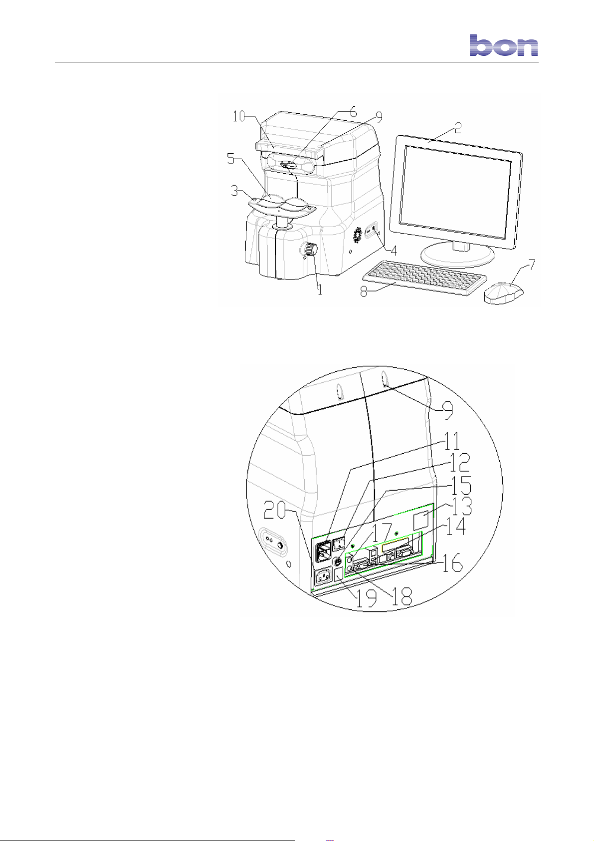
LLEEGGEENNDD
66..
1.
Chin rest height adjustment
knob.
2.
LCD monitor.
3.
Paper-holder pins on chin
rest.
4.
Instrument computer ON
pushbutton.
5.
Chin rest.
6.
Optical unit.
7.
Mouse.
8.
Keyboard.
9.
Instrument head assembly
screws.
10.
Forehead rest.
11.
Power socket with fuse holder
compartment and voltage
changer.
12.
Main switch.
13.
Data plate.
14.
USB socket (printer
connector).
15.
Monitor fuse 0.5A T.
16.
Monitor connector socket.
17.
Mouse connector socket.
18.
Keyboard connector socket.
19.
Monitor outlet socket data
plate.
20.
Monitor power socket (max.
output 50W).
21.
Optical unit lock screws (see
pag. 25).
22.
Lamp door screws.
23.
Optical head unit.
24.
Optical head power
connector.
25.
Firewire signal connector.
26.
Lamp maintenance door (see
pag. 25).
27.
Flash lamp (see pag. 25).
28.
12V 30W halogen projector
lamp (see pag. 25).
29.
Antivibration plate.
30.
Videocamera driver cable
Page 8 of 45
Page 10
77.. IINNSSTTAALLLLAATTIIOONN
The instrument as supplied is packed for best withstanding standard
shipping and warehousing conditions. Should you notice defects
attributable to shipping when unpacking the instrument, contact your
installation service.
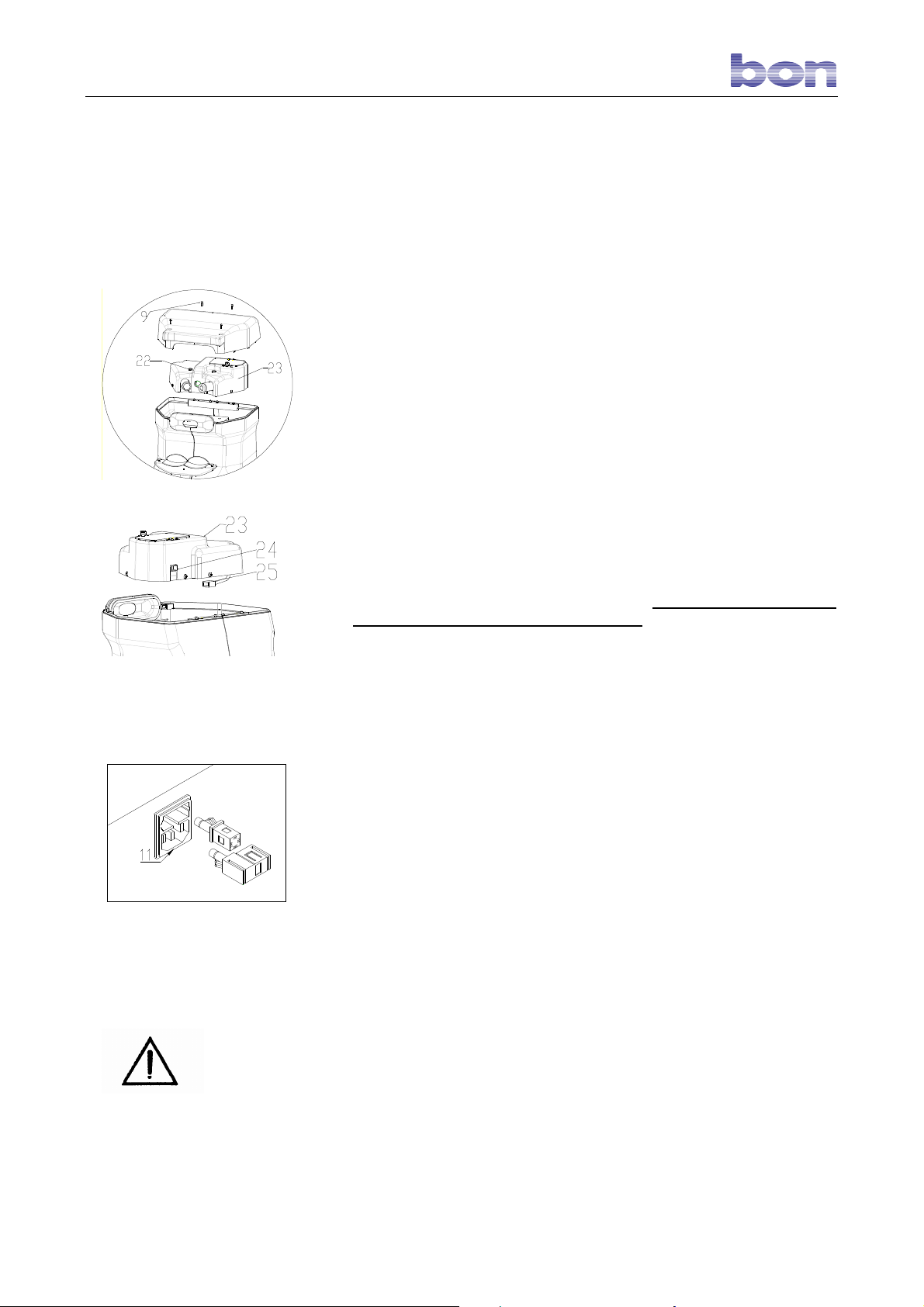
7.1. UNPACKAGE THE INSTRUMENT AND
REASSEMBLING THE OPTICAL HEAD (23)
For reasons of mechanical safety, the instrument is shipped with the
optical head disassembled and separately packed. Unpack the
instrument and proceed as described below to reassemble.
1) Loosen screws (9) and remove the optical head casing.
2) Take off the antivibration plate (29);
3) Connect the power cable (24) and the signal cable (25) to the
optical head.
4) Insert the optical head in the instrument and lock in place by
Connect the instrument to the::
Respect the precautions explained below for correct use of the
instrument.
tightening the lock screws (21).
5) Reassemble the optical head casing and lock in place by
tightening screws (9).
Place the instrument on a stable surface close to the monitor and
keyboard to create an ergonomically-sound and comfortable
workstation layout.
No software installation is required since the necessary software is
pre-installed on the built-in instrument PC.
7.2. CONNECTING THE INSTRUMENT
- monitor, using the VGA video cable (16) and the power cord
(20). Warning ! Maximum admissible monitor power is 50
W.
- keyboard (socket 18).
- mouse (socket 17).
- power supply. Before connecting, check the setting of the
voltage changer on the power socket (11), which must be set to
the voltage at which the instrument will be used. If necessary,
extract the relative cells and rotate until the correct voltage
value appears in the window.
- printer (if used), using the parallel port or USB socket (14)
(recommended).
7.3. PRECAUTIONS
In order to guarantee that the instrument always operates
correctly, perform maintenance as described in this manual.
Before using the instrument, check that the fixation point and
the instrument flash system operate correctly.
Take special care when examining children and subjects with
Page 9 of 45
Page 11

The result analysis must be done by a medicine doctor specialist.
occluded corneas. It may be impossible to acquire images of
the epithelium of the corneas of these subjects.
Always check that the patient’s chin is correctly positioned on
the chin rest and his forehead is firmly placed against the
forehead rest.
There are endothelia which could be acquired with a certain
difficulties, and can give ambiguous result. These can be:
irregular corneas, recently-treated patients (3-4 days), patients
suffering from keratoconus.
Check that the patient’s eye is not obstructed by the lid or
lashes, and that there are no teardrops on the eye surface, lids,
or lashes. If necessary, help the patient open his eyelids fully or
dry his eyes before beginning examination.
Acquisition is not possible if the patient is wearing contact
lenses or intra-ocular lenses.
Page 10 of 45
Page 12
88.. IINNSSTTRRUUCCTTIIOONNSS FFOORR UUSSEE
8.1. LAUNCHING THE SOFTWARE
All the software required for using the BON OPTIC specular microscope is pre-installed on the instrument’s
built-in computer. This PC does not support installation of other types of software. In order not to jeopardize
the instrument performance level and/or correct operation, do not install software for other uses on this PC.
Press button (4) to switch on the instrument. After the operating system has booted, double-click the
“ANKAA” desktop icon to launch the software.
8.2. THE MAIN WINDOW
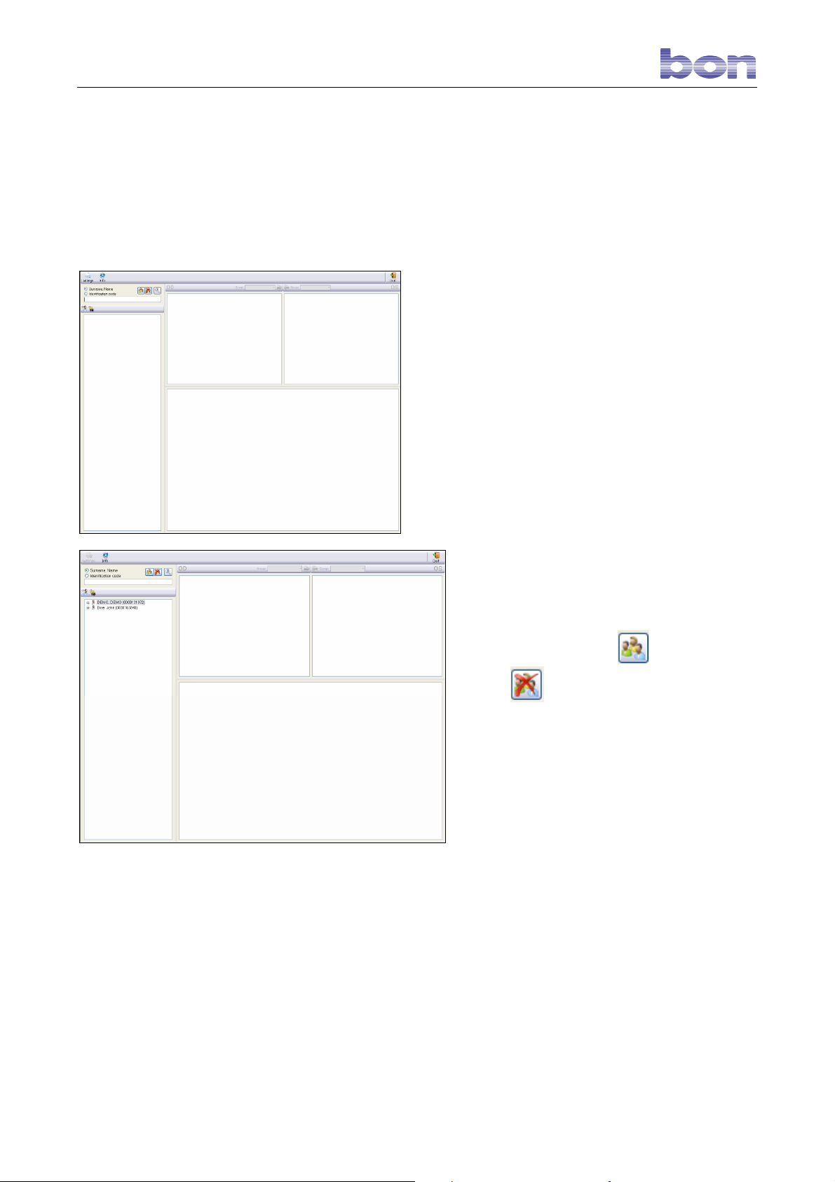
When the software is launched, the screen will
display the main window shown in figure 1.
Fig. 1 – Main wIndow
Fig. 2 – Patient list
The top of the window contains some
commands which will be described below.
On the left is the LIST PATIENTS, which is
accessed by pressing the
With the
patients.
button is emptied textbooks
button.
Page 11 of 45
Page 13
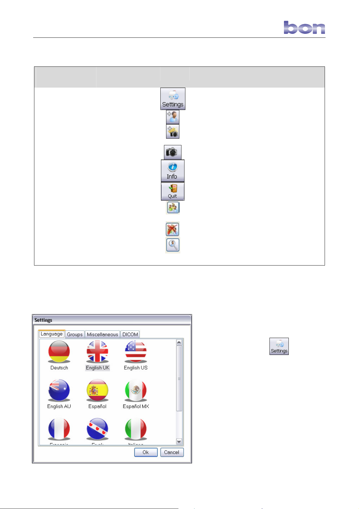
8.3. TOOLBAR BUTTONS SUMMARY
BUTTON
KEYBOARD
SHORTCUT
ICON
FUNCTION
Settings
New Patient
New Exam
Capture
Info
Esc
Open patient list
Empty patient list
Extended
examination
Fig. 3 – Main Window Commands
-
Space bar
8.4. SETTINGS
-
-
-
-
-
-
-
Opens the general settings and database settings
panel.
Allows the user to create a new patient.
Allows the user to create a new examination.
Accesses the CAPTURE screen.
Displays general information on software and
database versions.
Closes the program.
Open the patient list
Empty the patient list
Open window for extended examination
To access system settings, empty the patients
list, if open, and then click
.
In this section, the user may change:
-
the language used by the software
-
the pathology groups to be attributed to
the single examinations
-
the database configurations
-
the DICOM configurations.
8.4.1 LANGUAGE
The first screen allows the user to select the
language used by the software (Fig. 4).
Fig. 4 – Settings
Page 12 of 45
Page 14
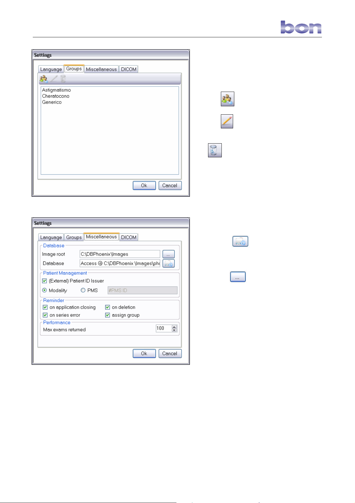
8.4.2 GROUPS
Select the GROUPS menu to manage the
pathology groups to be assigned to each
examination, distinguishing between right eye
and left eye (OD/OS) (Fig. 5).
Fig. 5 - Groups
Click the
Click the
group.
The
group.
This function is applicable only if the group
selected has not been matched with any
examination currently in the database.
button to create a new group.
button to edit a pre-existing
button allows the user to delete a
8.4.3 MISCELLANEOUS
The MISCELLANEOUS menu is
composed of 4 sections:
Database
Click the button to select the
reference database file path,
phoenix.mdb.
Fig. 6 - Miscellaneous
Use the button to locate the file
path of the root.cso file, which indicates
the folder containing the images.
Patient Management
Select the (External)Patient ID issuer box
to automatically assign a new ID code
every time a patient is created.
It is also possible to obtain the code from
an external database, using the PMS
mode.
If the Patient ID box is deselected, it will be
possible to insert the ID code each time a
new patient is created.
Reminder
Selecting the four options in this section
enables display of alarm and confirmation
messages.
Performance
This section allows the user to select the
number of examinations displayed at any
Page 13 of 45
Page 15
one time in the patients list. In the Figure 6
example: 100 examinations.
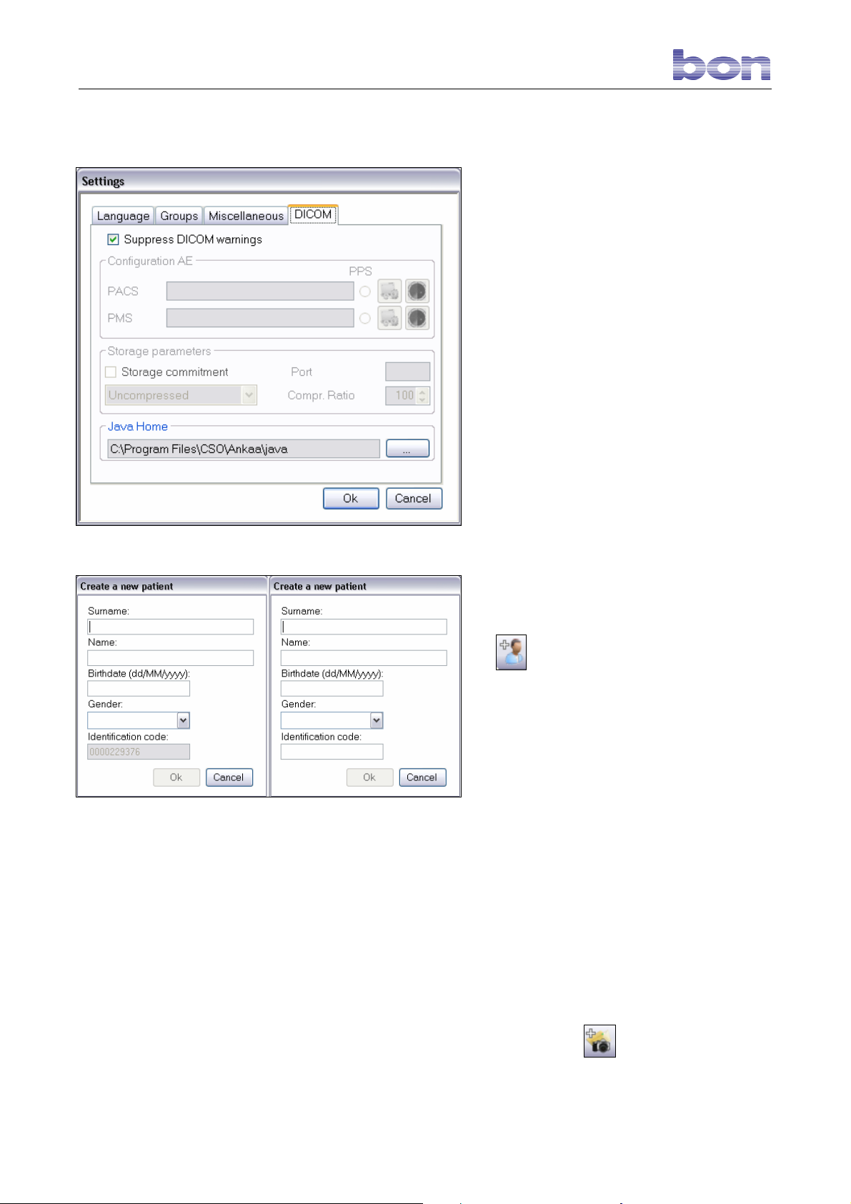
8.4.4 DICOM
If the Suppress DICOM warnings
box is selected, the menus and alarm
messages referred to DICOM management
will not be displayed.
Deselecting this box allows the user to
manage the PACS and PMS configurations
needed for DICOM data transfer.
For explanations about DICOM, see the
relative section below.
Fig. 7 – DICOM
Fig. 8 – Create new patient
8.5. Patient Management
8.5.1 CREATING A NEW PATIENT
To create a new patient, click the
icon (see Fig. 1).
The new patient personal data entry
window will open
(Fig. 8).
Type in the last name, first name, and date
of birth; indicate gender.
In the right-hand window, enter the
identification code if the Patient ID box has
been deselected (Figure 6).
Click OK after all the required personal
data has been entered.
8.5.2 CREATING A NEW
EXAMINATION
After a new patient is created, an
examination will be created automatically
and the capture screen will open.
To create an examination for a patient
already in the archive, select the patient
and click the button.
A new examination will be created and the
capture screen will open.
Page 14 of 45
Page 16
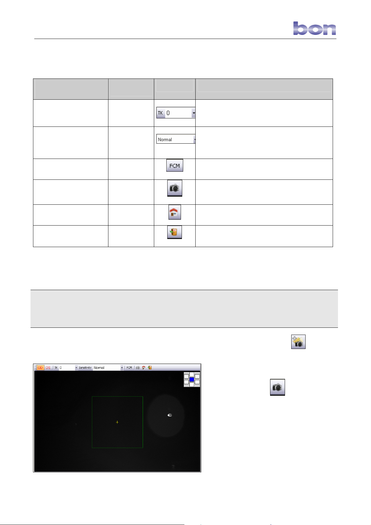
8.6 CAPTURE
8.6.1 CAPTURE WINDOW COMMANDS
BUTTON
TK
Sensitivity
FMC
Capture
Home Position
Esc
Follow the procedure outlined below to acquire an image. Position the patient’s chin on the chin rest. The
chin rest automatically detects correct placement for right eye (OD) or left eye (OS) capture.
Left eye capture
Position the patient’s head on the RIGHT SIDE of the chin
rest; check that the patient’s forehead rests correctly on the
forehead rest. If the patient is correctly positioned the
reflection of the cornea will fall within the green square.
The capture mode is automatic.
KEYBOARD
SHORTCUT
-
-
-
Space Bar
-
Esc
ICON
FUNCTION
Allows the user to select the correction to be applied for
different corneal thicknesses.
Allows the user to select the video camera sensitivity
threshold (High, Normal, Low) for working with opaque,
normal, and highly reflective corneas, respectively.
Allows the user to enable the correct capture procedure for
corneas with very large curvature radiuses.
Enabled when the patient is correctly positioned. Allows the
user to capture the image.
Returns the optical head to the “rest” position.
Exits the capture window.
Right eye capture
Position the patient’s head on the LEFT SIDE
of the chin rest; check that the patient’s
forehead rests correctly on the forehead rest. If
the patient is correctly positioned the reflection
of the cornea will fall within the green square.
Select the patient and click the icon to
create a new examination and access the
capture screen. If the patient has not been
closed, capture may continue using the same
examination. In this case the “new exam” icon
will be replaced by the
icon.
A green square delimiting the instrument
scanning quadrant, with a center cross-hair,
will appear.
In the LIVE mode, the instrument positions
itself to capture the endothelium in the central
corneal area. To capture the endothelium in a
peripheral area, click the icon of the desired
area:
Fig. 9 – Incorrect patient positioning
Page 15 of 45
Page 17
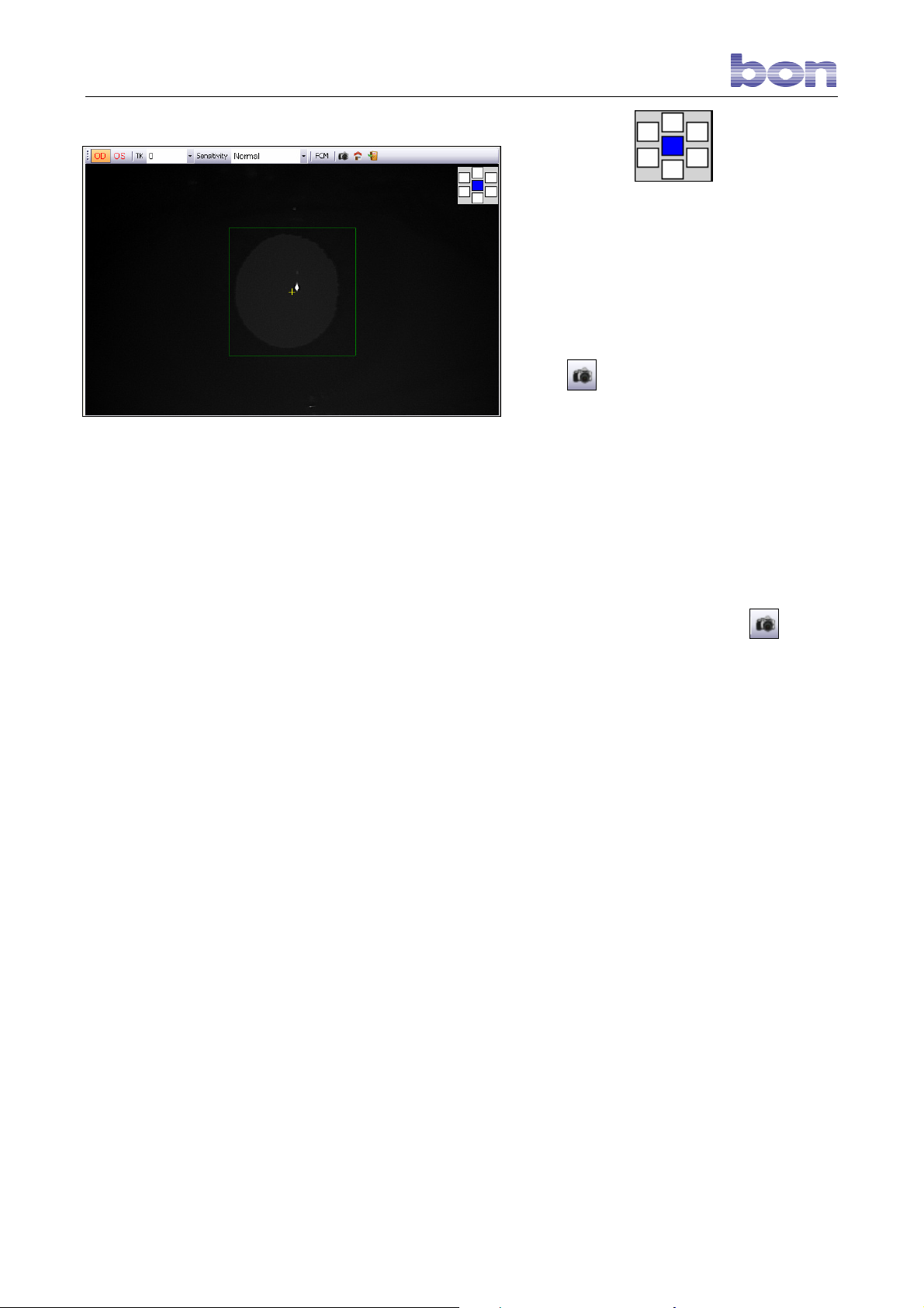
Fig.10 – Correct patient positioning
Now position the patient’s head on the right
side of the chin rest to capture the left eye or,
vice-versa, on the left side to capture the right
eye.
Check that the patient’s chin is solidly
positioned on the chin rest and the forehead on
the forehead rest.
If the patient is not correctly positioned, the
reflection will fall outside of the green square
and the
the patient’s head, if necessary changing chin
rest elevation, until the reflection of the eye
falls within the scanning quadrant as shown in
Fig. 10.
Ensure that the patient always looks directly at
the fixation point inside the instrument and
does not close the eye during the examination.
The reflection of the eye in the scanning
quadrant must be in focus. Use the and
keyboard arrows to optimize focus.
icon will be disabled Fig. 9. Move
To start the examination, click the
button or press the SPACE BAR. The
instrument will automatically capture the image
of the endothelium and, at the end of this
operation, display it in the gallery. The preview
will be visible in the foreground with the ruler at
the top.
(Fig. 11)
capture
Page 16 of 45
Page 18
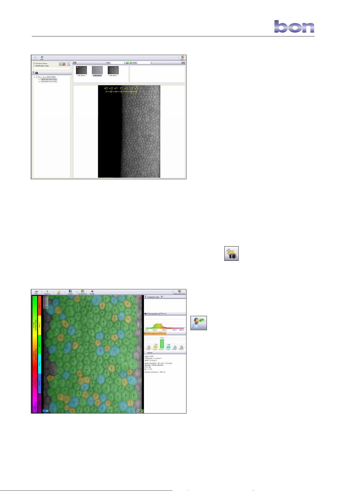
Fig. 11 – Gallery image
To view the preview of another image, simply
select it.
Double-click the gallery image to proceed with
processing.
8.7 ANONYMOUS CAPTURE
This new capture mode permits capturing and
processing an image without attributing it to any
patient.
To access this mode, empty the patients list
and click the toolbar button.
Following capture, the instrument automatically
accesses the processing screen. Fig.12
It is always possible to create a new patient to
which to assign the image After processing has
been completed and any operations of interest
have been carried out. Simply click the
button to open the “create new patient”
screen. After the data has been saved, the
patient will be visible in the gallery.
Fig. 12 – Anonymous capture
Page 17 of 45
Page 19
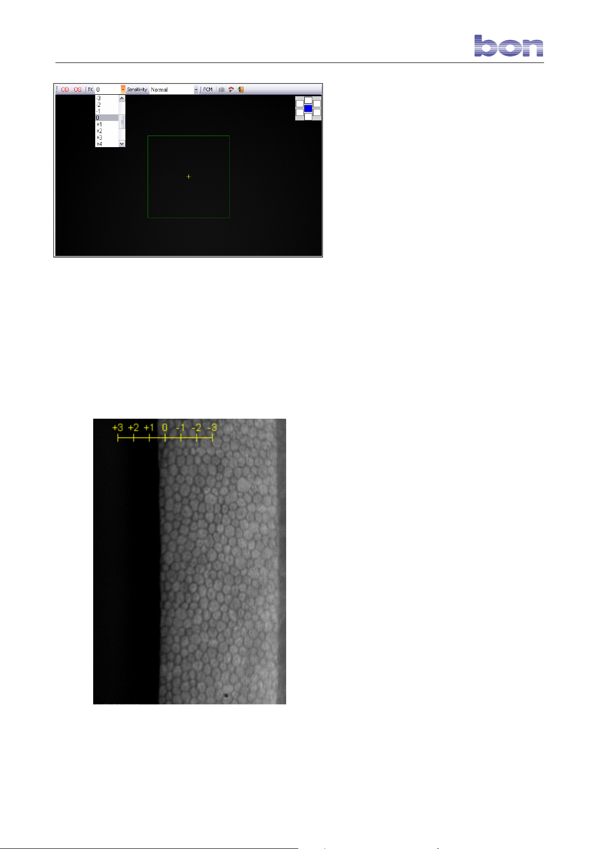
Fig. 13 – Corrections menu
8.8 CAPTURING CORNEAS
WITH DIFFERENT
THICKNESSES
A new cursor has been added to regulate the
quality of capture of corneas with differing
thicknesses. This cursor contains various
values from -5 to +5 with a default 0 position at
the center. In general, if the patient is correctly
positioned and the cornea is normal, the cursor
may be left in the 0 position.
The effect produced by thicker-than-normal
corneas is to yield images that are not perfectly
in focus on the left-hand side. In this case,
move the cursor to the positive values to obtain
images in better focus.
The effect produced by thinner-than-normal
corneas is to yield images that are not perfectly
in focus on the right-hand side. In this case,
move the cursor to the negative values to
improve capture.
8.8.1 EXAMPLES
To aid in understanding the correct correction
value to be used, an indicative scale is
displayed over the preview image.
In order for the pachymetric datum supplied by
the instrument to be reliable, the image must
be perfectly focused and the left edge of the
captured image must correspond to the “0”
value on the scale at the top of the screen
(Figure 14).
Fig. 14 – Focused image
Page 18 of 45
Page 20
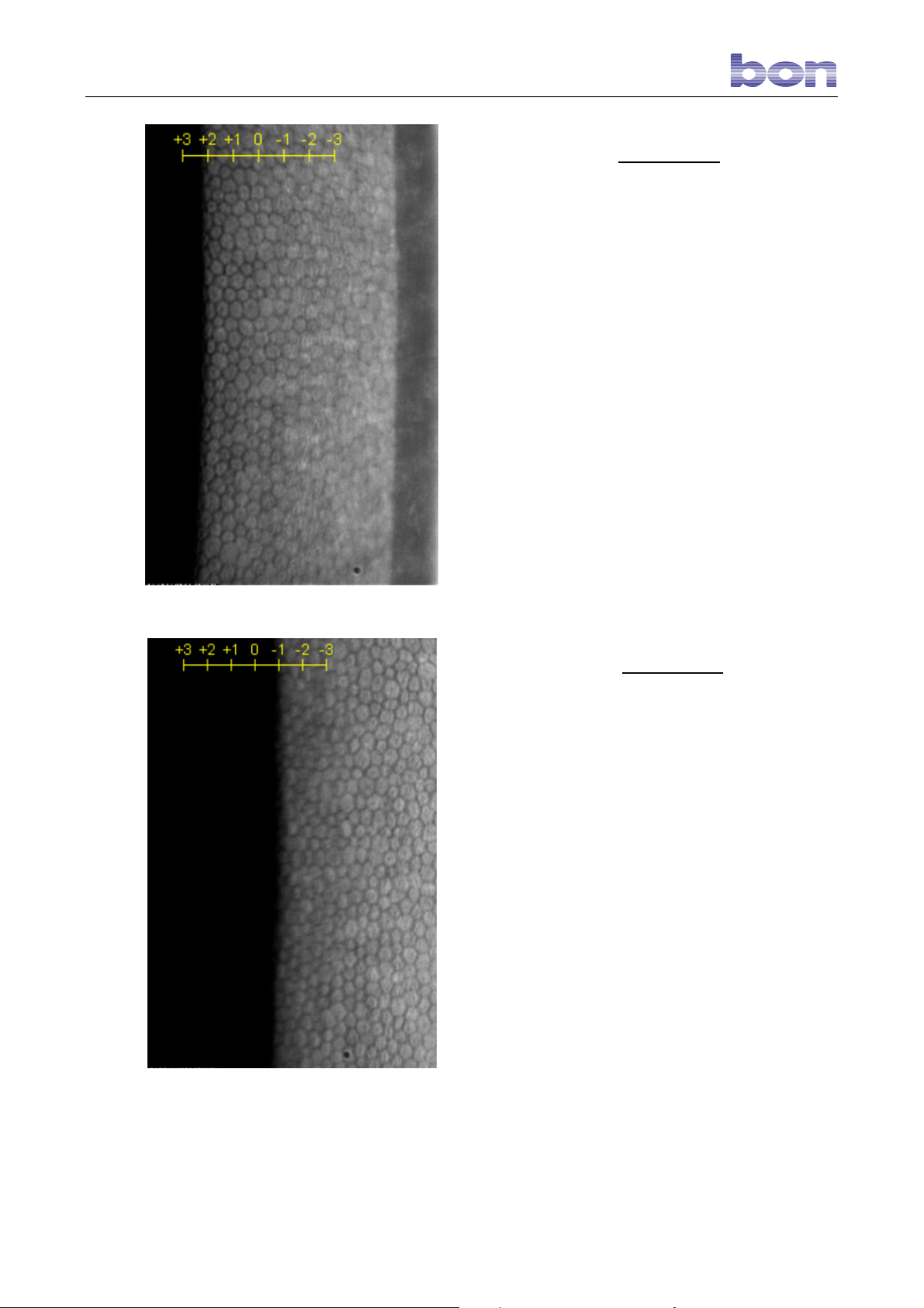
If the left edge of the image corresponds to a
positive value, repeat capture after setting the
cursor to the corresponding scale value. In the
example (Figure 15), repeat the capture with
the thickness value set to “+2.”
Fig. 15 – Positive correction
If the left edge of the image corresponds to a
negative value, repeat capture after setting the
cursor to the corresponding scale value. In the
example (Figure 16), repeat the capture with
the thickness value set to “-1.”
Fig. 16 – Negative correction
Page 19 of 45
Page 21
8.9 REMOTE CONTROL
The new SP-02 is equipped with an infrared remote control for greater operator convenience when using the
instrument.
The remote can be used to:
- switch off the instrument.
- align and focus the corneal reflection before beginning capture.
- select the area of the cornea to capture.
- start capture.
- introduce correction for corneal thickness before capture.
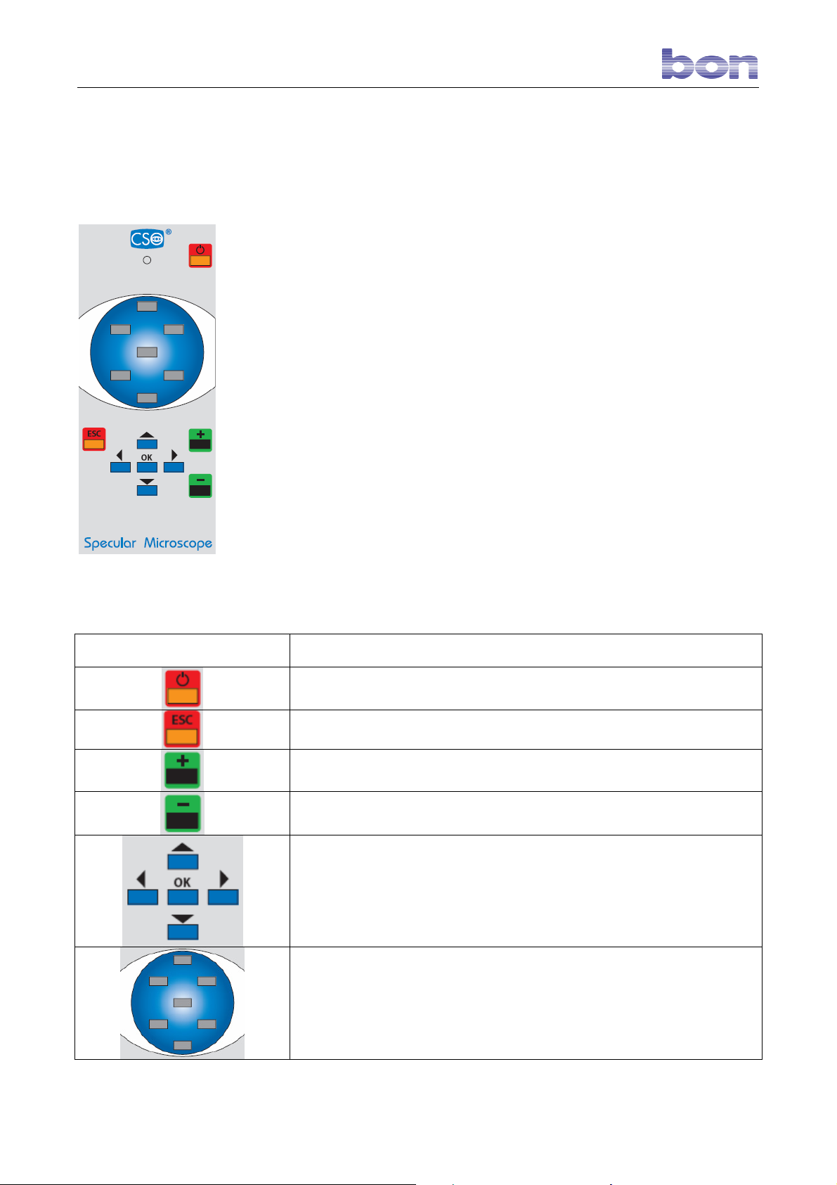
8.10 THE REMOTE CONTROL KEY FUNCTIONS
KEY
Exits the ”specular microscope” software.
FUNCTION
ESC function, for canceling a command or exiting the “specular microscope” program.
Increases the capture index for thicker corneas.
Decreases the capture index for thinner corneas.
Allows the user to move the optical head:
- to the right and left for centering the corneal reflection.
- forward and backward for fine-focusing the corneal reflection.
The OK key starts capture.
Pressing the OK key from the main page opens the patients list.
Allows the user to select the corneal area to be captured:
- center area
- 6 peripheral areas corresponding to the clock-dial positions
12, 2, 4, 6, 8, 10.
Page 20 of 45
Page 22
8.11 USING THE REMOTE CONTROL FOR IMAGE CAPTURE
Follow the procedure outlined below when using the remote control for image capture. Position the patient’s
head on the chin rest, which automatically detects the right eye (OD) or the left eye (OS).
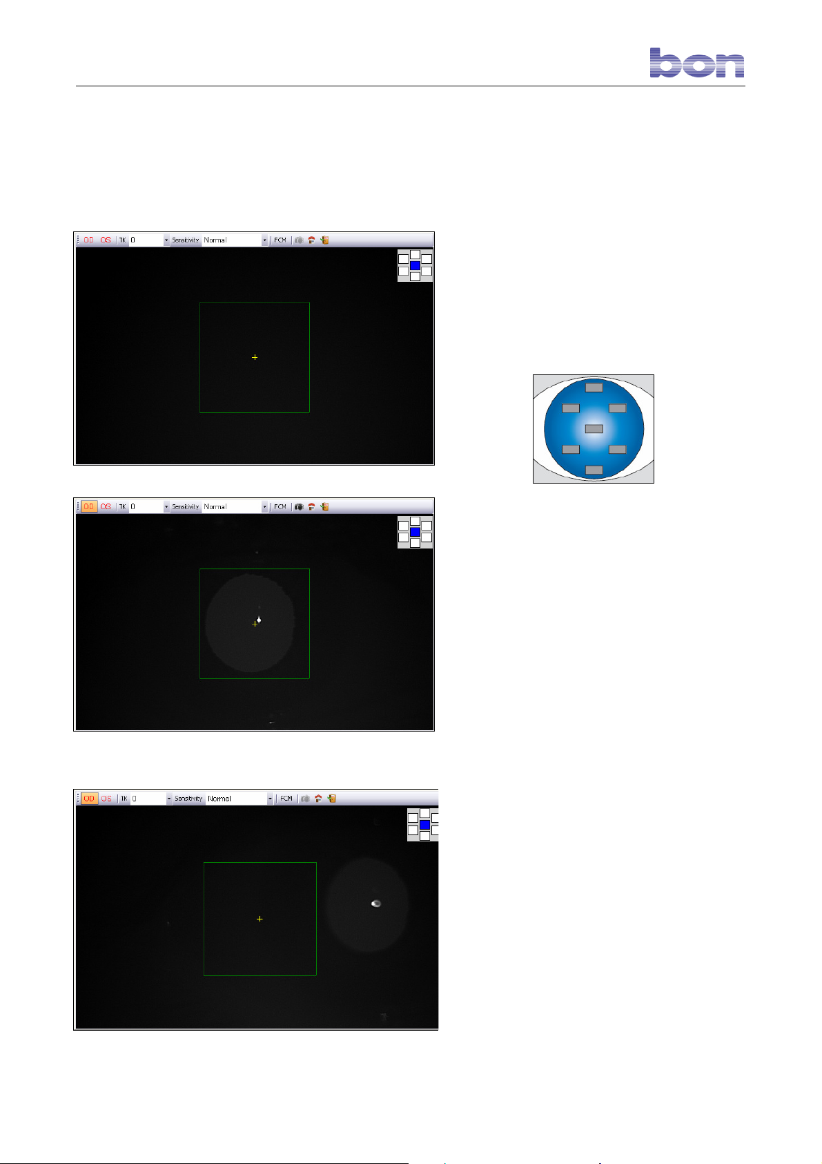
Click the “capture” button on the main screen to
access the capture screen.
In the LIVE mode, the instrument positions itself
to capture the endothelium in the center area of
the cornea. To capture the endothelium in a
peripheral area, press the remote control key
corresponding to the area of interest:
Fig.17 – Capture window
Fig. 18 – Correct patient positioning
Position the patient’s head on the RIGHT SIDE
of the chin rest. Check that the patient’s forehead
is correctly resting on the forehead rest. If the
patient is correctly positioned, the reflection of
the cornea will be centered in the green square.
(Fig. 18).
Position the patient’s head on the LEFT SIDE of
the chin rest. Check that the patient’s forehead is
correctly resting on the forehead rest. If the
patient is correctly positioned, the reflection of
the cornea will be centered in the green square.
Check that the patient’s chin and forehead are
correctly and snugly positioned; ensure that the
patient looks directly and steadily at the fixation
point, with his eye fully open.
Check that the reflection of the cornea shown on
the screen falls within the scanning quadrant and
that it is perfectly focused. If necessary, use the
remote control arrow keys to adjust the reflection
and to change chin rest height.
If the reflection does not fall within the scanning
quadrant, the “capture” button is not enabled.
(Fig. 19).
Fig. 19 – Incorrect patient positioning
Page 21 of 45
Page 23
To begin the examination, press the OK key on
the remote
or press the SPACE BAR. The instrument will
automatically capture the image of the
endothelium and, at the end of this operation,
display it in the gallery.
8.11.1 EXAMPLES
In order for the pachymetric datum supplied by
the instrument to be reliable, the image must be
perfectly focused and the left edge of the
captured image must correspond to the “0” value
on the scale at the top of the screen (Fig. 20).
Fig. 20 – Focused image
Page 22 of 45
Page 24
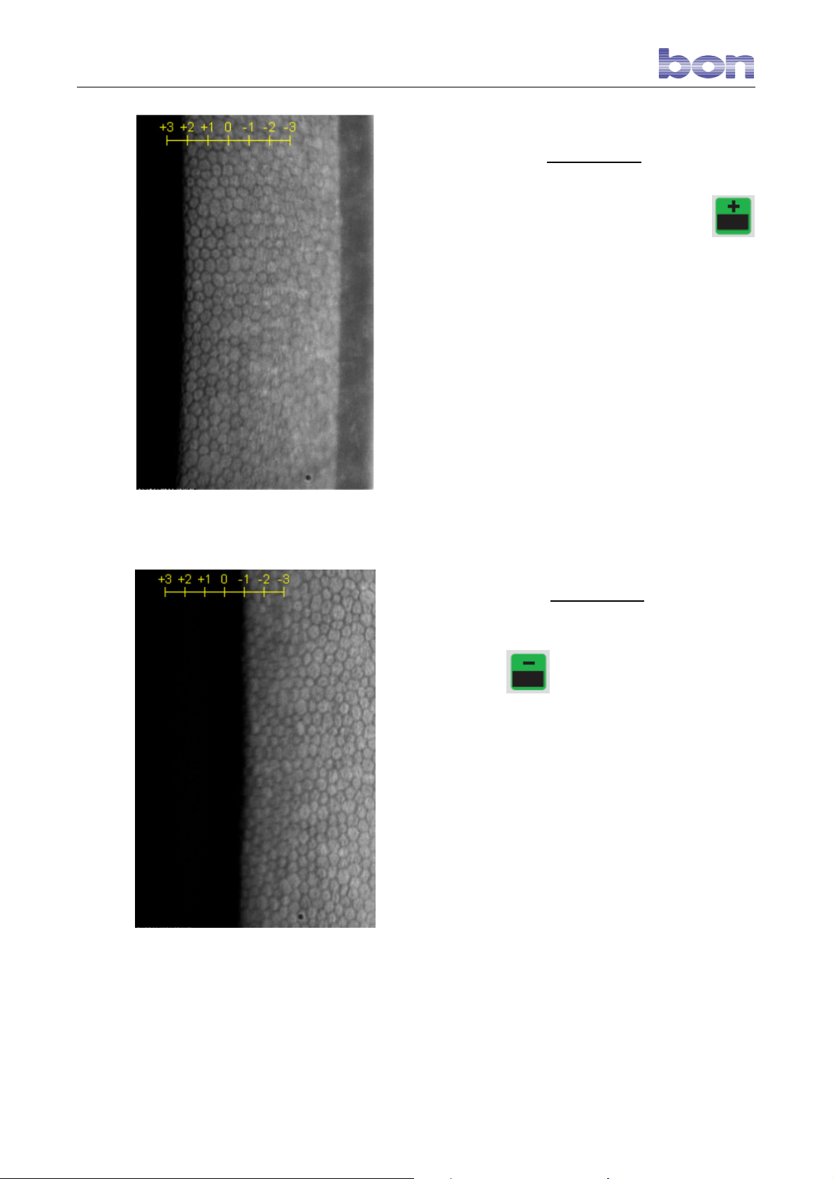
Fig. 21 – Positive correction
If the left edge of the image corresponds to a
positive value, repeat capture after setting the
cursor to the corresponding scale value (Fig. 21).
In the example, repeat the capture after setting
the thickness value to “+2” using the
remote control key.
If the left edge of the image corresponds to a
negative value, repeat capture after setting the
after setting the cursor to the corresponding scale
value. In the Figure 22 example, repeat the
capture after setting the thickness value to “-1”
Fig. 22 – Negative correction
using the remote control key.
Page 23 of 45
Page 25
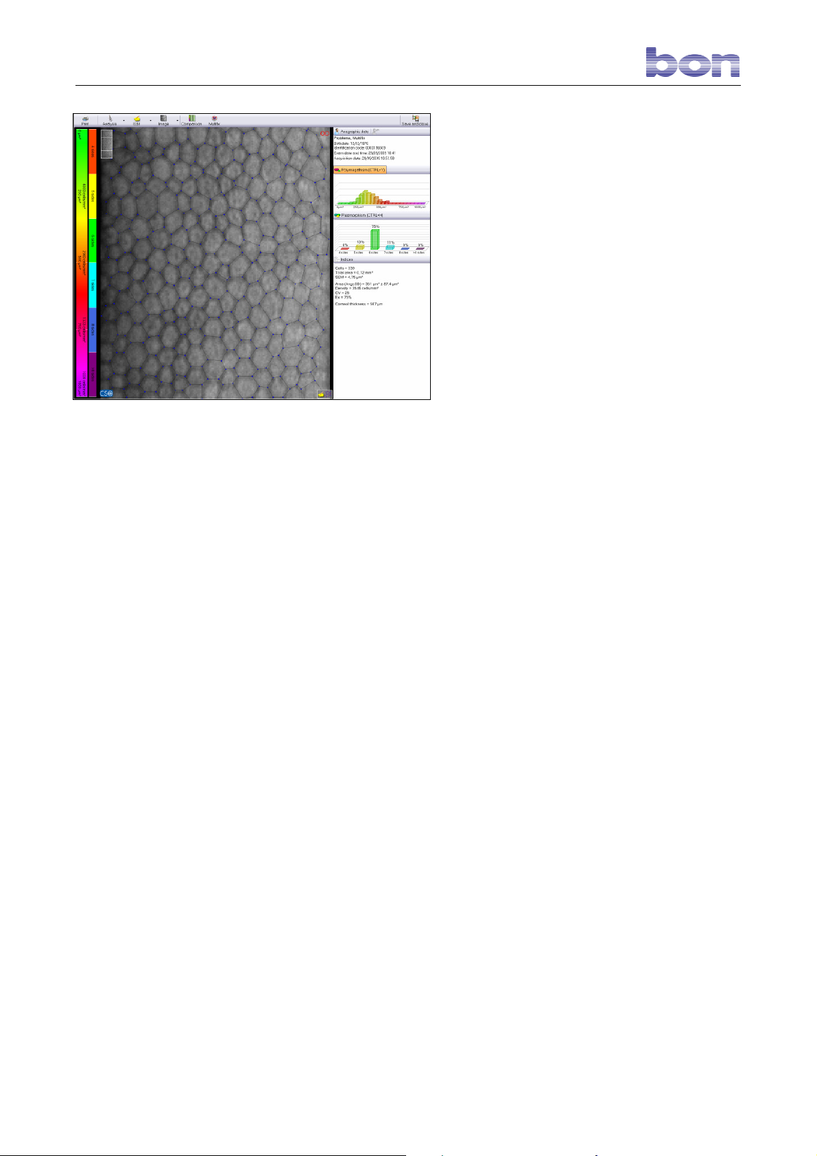
Fig. 23 – Cell editing
8.12 AUTOMATIC CELL COUNT
Double-click the gallery image to access the
environment for processing the captured image.
The data analysis screen will open. (Fig. 23)
The system will automatically proceed with
recognition of the endothelial cells.
After having launched automatic cell count, the
operator must verify that the borders identified by
the software correspond to the real borders
visible on the screen. The processing result may
be modified if the software has skipped or
erroneously identified some cells. The better the
correspondence between the real and the
identified borders, the more reliable the results.
Using the mouse, the operator may:
- Add new points identifying the cell
borders, with the left mouse key.
- Delete points, with the right mouse key.
Page 24 of 45
Page 26
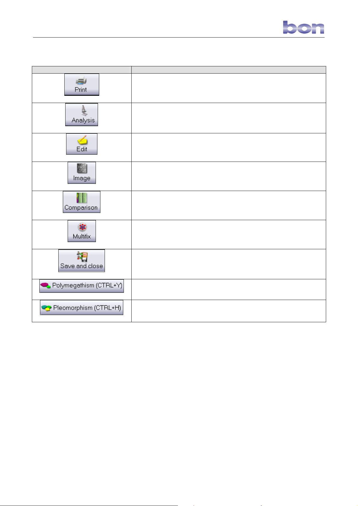
8.12.1 TOOLBAR BUTTONS AT THE TOP OF THE SCREEN
BUTTON FUNCTION
Prints the processed image.
Shows the processed image after editing.
Allows the user edit the cells.
Modifies the image display parameters.
Allows the user to compare two processed images.
Shows all the processed images referred to different areas of the
endothelium in a single screen.
Saves and closes processing.
Presents polymegatism processing results.
Presents pleomorphism processing results.
Page 25 of 45
Page 27
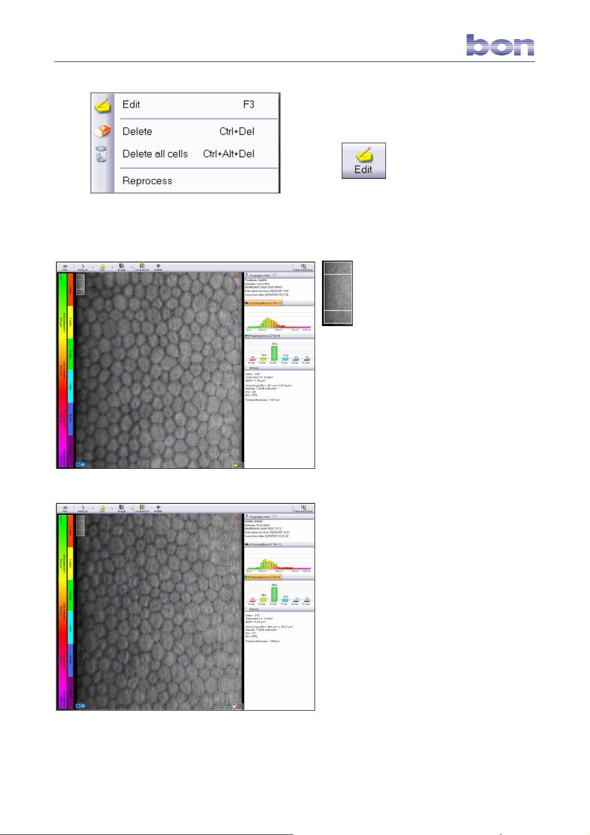
Fig. 24 – Editing Menu
Fig. 25 – Edit cells
Fig. 26 – Delete cells
8.12.2 EDITING SELECTED CELLS
To access the cell modification functions, click
the
and select Edit .
To view all the areas of the endothelium, scroll
the image with the up ↑ and down ↓ keyboard
arrows or hold down the left mouse key and
drag the image. The figure on the upper left
button or open the menu (Fig.24)
indicates the portion analyzed.
To add a point to a border in the image, simply
left-click. Holding down the right mouse key
selects and the point closest to the cursor and
highlights it with a red dot. In this case, it may
be deleted by pressing the CANC keyboard key.
When a point remains isolated and is not part of
a complete cell, it will be displayed in yellow.
(Fig. 25).
8.13 DELETING CELLS
Open the Edit menu and select Delete. Hold
down the left mouse key to display a circular red
cursor. As this cursor is moved over the image it
deletes all the cells it touches (Fig.26).
To delete all the cells, select Delete all cells.
To re-edit the cells, click Reprocess.
Page 26 of 45
Page 28
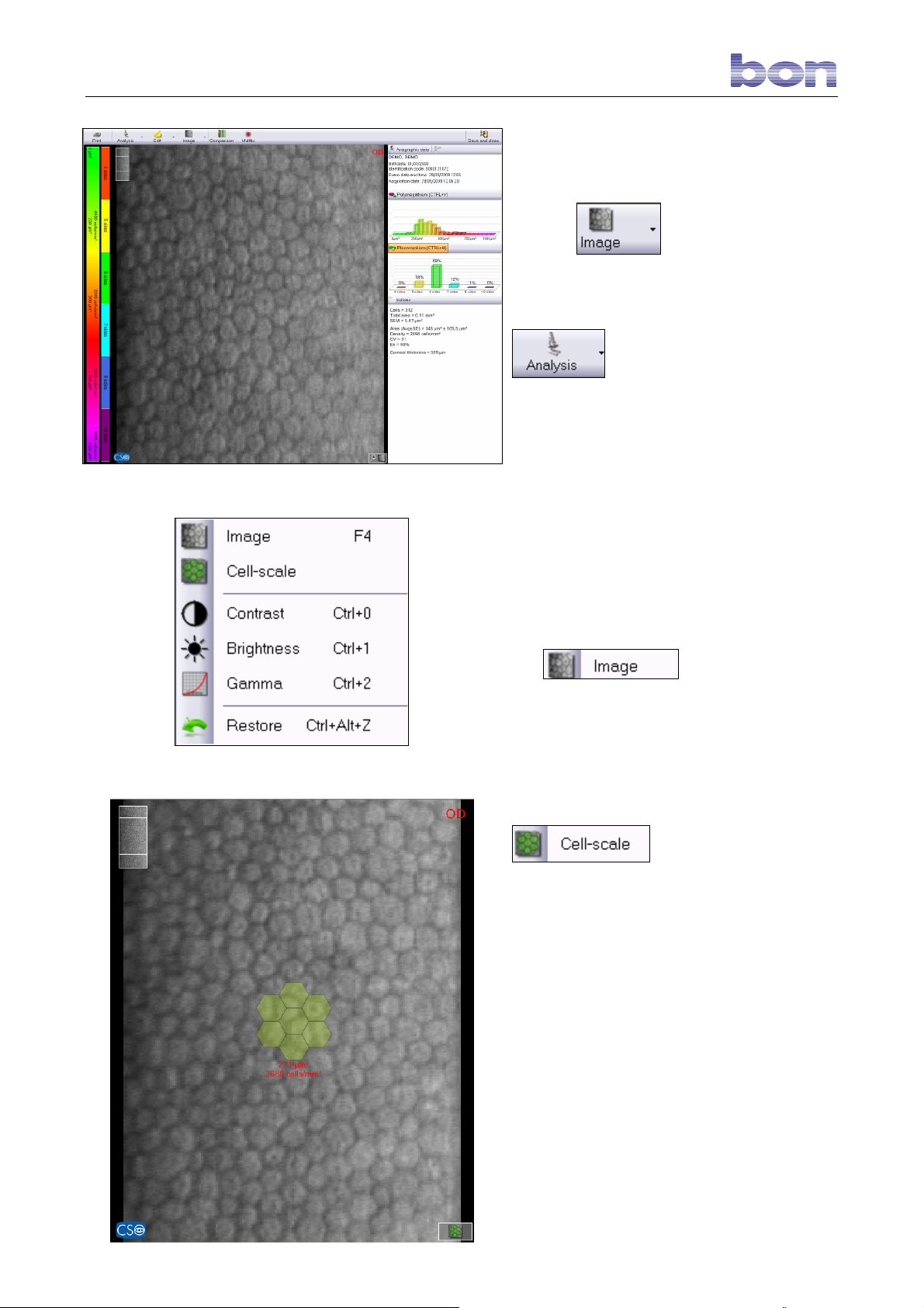
Fig. 27 – Image of endothelium
8.14 EDITING IMAGE
PARAMETERS
Click the
unprocessed image of the endothelium in the
foreground.
To return to the processed image, click the
button.
Clicking the arrow at the side of the image
button opens a menu (Fig. 28).
button to display the
Fig. 28 – Image menu
The
to the function described at the start of this
section. (Fig.27).
mean cell area scale.
Scrolling with the mouse wheel, if available,
displays all the dimensions and the color
reported in the scale at the side (Fig. 29).
function corresponds
shows the density and cell
Fig. 29 – Scale
Page 27 of 45
Page 29
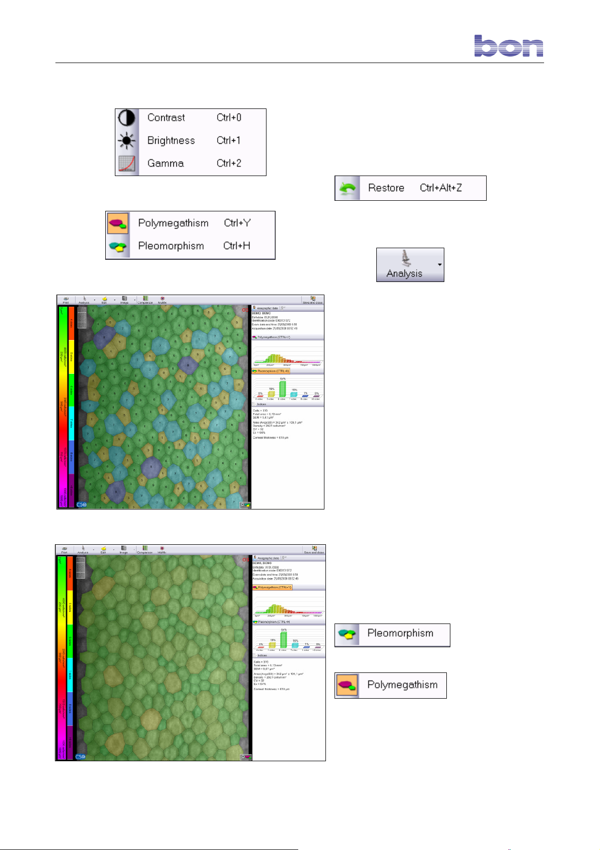
Fig. 31 – Analysis menu
Fig. 32 – Pleomorphism
Fig. 30 – Image parameters
The Figure 30 functions allow the user to
change the contrast, the brightness, and the
correction range applicable to the captured
image.
To eliminate any modifications made, select
.
8.15 PROCESSING
Click the button to process an
image. Two types of processing modes will be
presented:
- Pleomorphism: image by number of sides
per cell. (Fig.32).
- Polymegathism: image displayed by
surface area of each cell. (Fig.33).
To access the two processing types, open the
pull-down menu from the Analysis button and
select the desired item (Fig. 31).
Or click button :
or button
displayed on the right-hand side of the screen
above the relative diagrams.
The reference scales for polymegathism and
Fig. 33 - Polymegathism
for pleomorphism are shown on the left-hand
side of the screen.
Page 28 of 45
Page 30
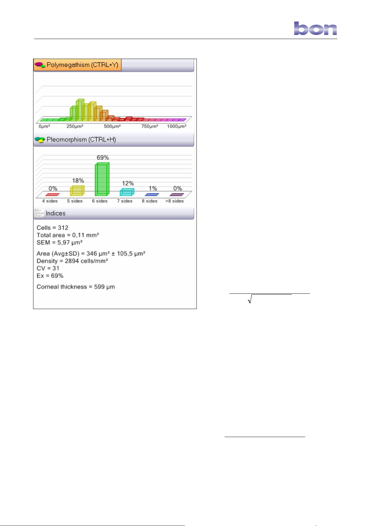
Fig. 34 – Analysis results
8.16 ANALYSIS RESULTS
The processing window on the right-hand side
of the screen displays the graphs and
numerical results.
The POLYMEGATHISM graph presents the
number of cells with surfaces within the
highlighted intervals.
The PLEOMORPHISM graph presents the
percentages of cells having like numbers of
sides, corresponding to the scale.
Cells : the number of cells counted for
processing.
Total area : the area of the endothelium
surface processed.
SEM (Standard Error of the Mean): evaluates
the reliability of the measurement by
comparing sample variability
(standard deviation of the area) with
the number of elements measured:
SEM =
Area (Avg±SD) : average cell surface area
with uncertainty given by standard deviation.
Density : density is given in cells per square
millimeter [cell/mm2]. An indicative normal
value for a young male is 2500-3000
cells/mm2.
CV (Coefficient of Variation): cell morphology
is expressed using the Coefficient of
Variation (CV), which is the ratio
between the observed standard
deviation and the arithmetic mean of
all the cells examined. With reference
to the Matsuda-Schultz index, an
average value is less than 35.
CV =
mediaArea
Ex (hexagonality index): the ratio between the
hexagonal (6-sided) cells and the total
highlighted cells.
Thickness: indicative pachymetric datum
AreadardtanSDeviazione
celleNumero
AreadardtanSDeviazione
Page 29 of 45
Page 31
relative to the part of the cornea
captured during the examination. The
accuracy of corneal thickness
measurement is strictly correlated
with the quality of the captured image
and for this reason the datum must
be considered only indicative and
approximate.
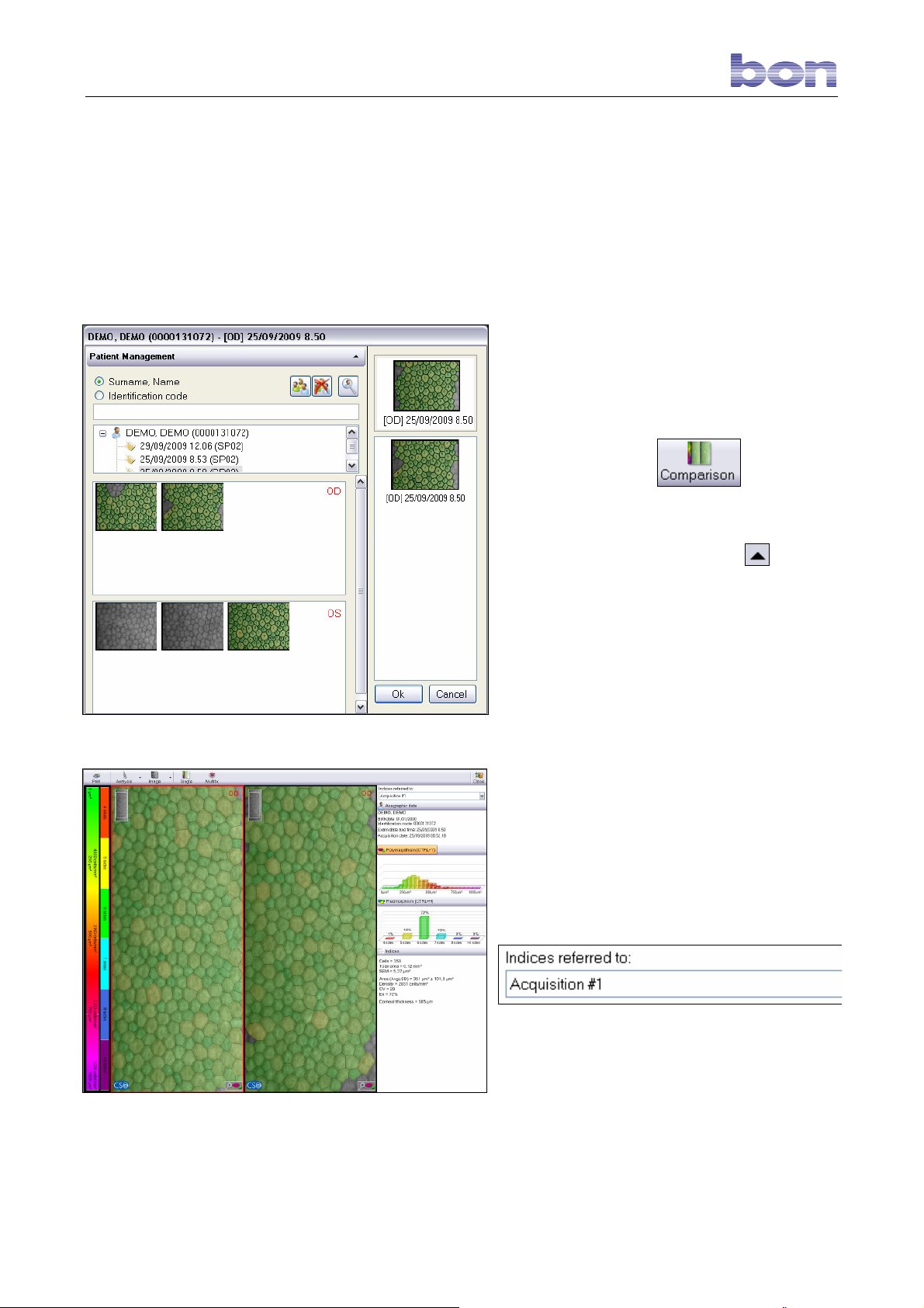
8.17 COMPARISON
The system allows the user to compare two
captures. This function is especially useful for
monitoring a patient’s progress or the evolution
of a pathology, or for comparing the pre- and
post-treatment condition of the cornea.
To access the COMPARISON function from the
Fig. 35 – Selecting images for comparison
main window, click the
toolbar.
Accessing the COMPARISON function opens the
window shown in Fig. 35. Click the
the top to select images of different
examinations. Once the examination is selected,
the relative gallery images will appear.
Double-click an image to be compared with the
starting image, shown on the top right. Only two
images may be compared at a time.
Click OK to confirm.
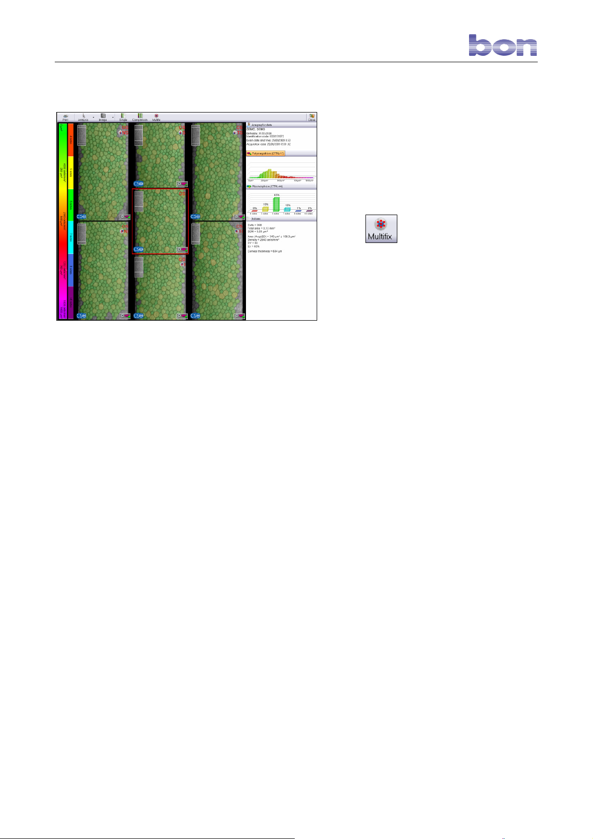
A screen comparing the two processed images
will open. The numerical values and the graphs
on the right of the screen refer to the image
highlighted by a red square.
To select the other image, simply click on the
image or open the menu on the top right,
button on the
button at
and select the other image.
In this case as well, there are two possible
Fig. 36 – Image Comparison
analysis types:
POLYMEGATHISM and POLYMORPHISM.
Page 30 of 45
Page 32
8.18 OVERALL COMPARISON
OF ALL THE CORNEAL AREAS
(Multifix)
When images of all the seven possible corneal
areas are captured (one central plus six
peripheral images), they may all be displayed in
a useful summary format called “Multifix.” This
function is active even when the acquisitions do
not cover all the possible areas.
Fig. 37 – Multifix
Click the
window.
A new screen will display all the images
referred to different areas of the endothelium.
button in the processing
OS or OD is indicated at the top of each image,
as is the reference to the area of the
endothelium photographed:
- ST: superior temporal
- IT: inferior temporal
- S: superior
- I: inferior
- SN: superior nasal
- IN: inferior nasal
The graphs and numerical values referred to
the selected area are shown on the right-hand
side of the screen, highlighted with a red
square.
Page 31 of 45
Page 33
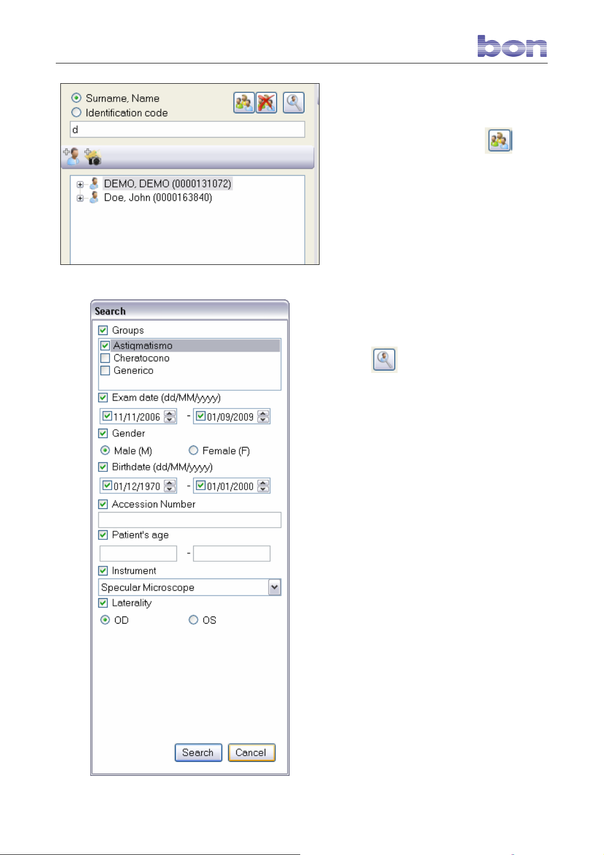
Fig. 38 – Patient search
Fig. 39 – Advanced search
8.19 OPENING A PATIENT FILE
IN THE ARCHIVE
To open the patients list, click the
To find a particular patient, type the first letter/s
of the last name in the command line. (Fig. 38).
Only the patients whose last names begin with
the letter/s entered will be displayed.
The ID code may also be used to find a patient.
Select the ID code box and type the number in
the command line.
button.
8.20 ADVANCED SEARCH
Click the button to run an advanced
search. Figure 38 shows all search criteria
selected; it is also possible to use only one
criterion
Select the box of interest:
- GROUPS: select this option to view all the
current groups. Select the groups that
correspond to the search criterion.
- EXAM DATE: enter two dates delimiting the
period of interest. In the Figure 38 example, all
examinations conducted in the period 11 Nov
2006 to 01 September 2009 will be displayed.
- GENDER: select Male or Female.
- BIRTHDATE: as in the case of the Exam
Date filter, enter two dates. All the patients
whose birth dates fall in the period so delimited
will be displayed.
- ACCESSION NUMBER: type in the
examination accession number.
- PATIENT’S AGE: in this case as well, enter
two values.
The search will return all the patients whose age
falls in the interval delimited by the two
numbers.
- INSTRUMENT: leave “Specular Microscope”
selected.
- LATERALITY: this menu opens only in the
case of a search by group, to allow the user to
select one of the two eyes as search criterion.
Click Search to start the search.
Page 32 of 45
Page 34
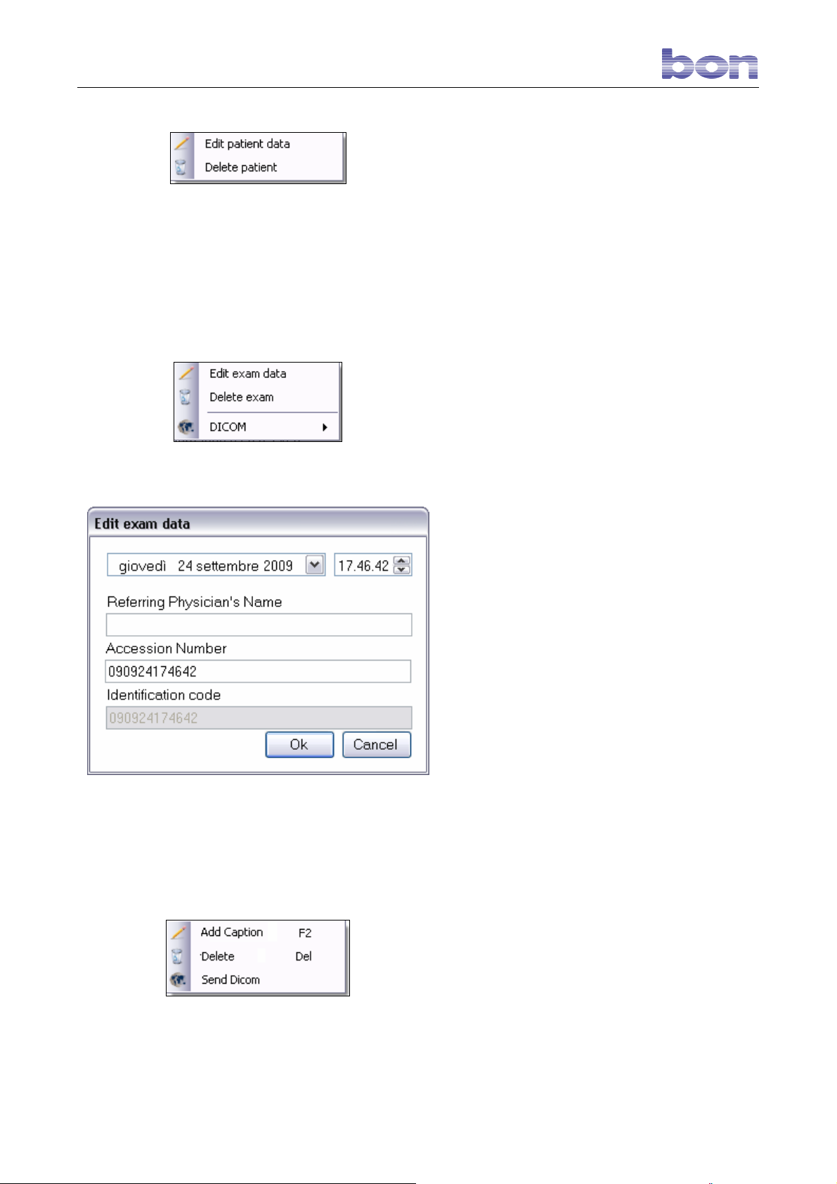
Fig. 40 – Edit, delete patient
Fig. 41 – Edit, delete examination
Fig. 42 – Examination data editing screen
Fig. 43 – Image management menu
8.21 PATIENT MENU OPTIONS
Select a patient and right-click. A menu opens.
(Fig. 40).
EDIT PATIENT DATA: allows the user to edit the
personal patient data.
DELETE PATIENT: permanently deletes the
patient, as well as all the attached examinations
and images, from the archive.
The software requests confirmation before
deleting all the patient data.
8.22 EXAMINATIONS MENU
OPTIONS
Select an examination and right-click. A menu
opens. (Fig. 41).
EDIT EXAM DATA: opens the screen shown in
(Fig. 42) for editing the examination date,
entering or changing the referring physician
and/or the accession number for advanced
searches.
EDIT EXAM: permanently deletes the selected
examination and all the associated images.
The program requests confirmation before
proceeding with deletion.
DICOM: accesses the DICOM standard
functions.
8.23 IMAGES MENU OPTIONS
Select a gallery image and right-click to open the
menu shown in Fig. 43.
ADD CAPTION: adds a short description, shown
in the gallery, for each image.
DELETE: permanently deletes an image from
the gallery. The program requests confirmation
before proceeding with deletion.
Page 33 of 45
Page 35
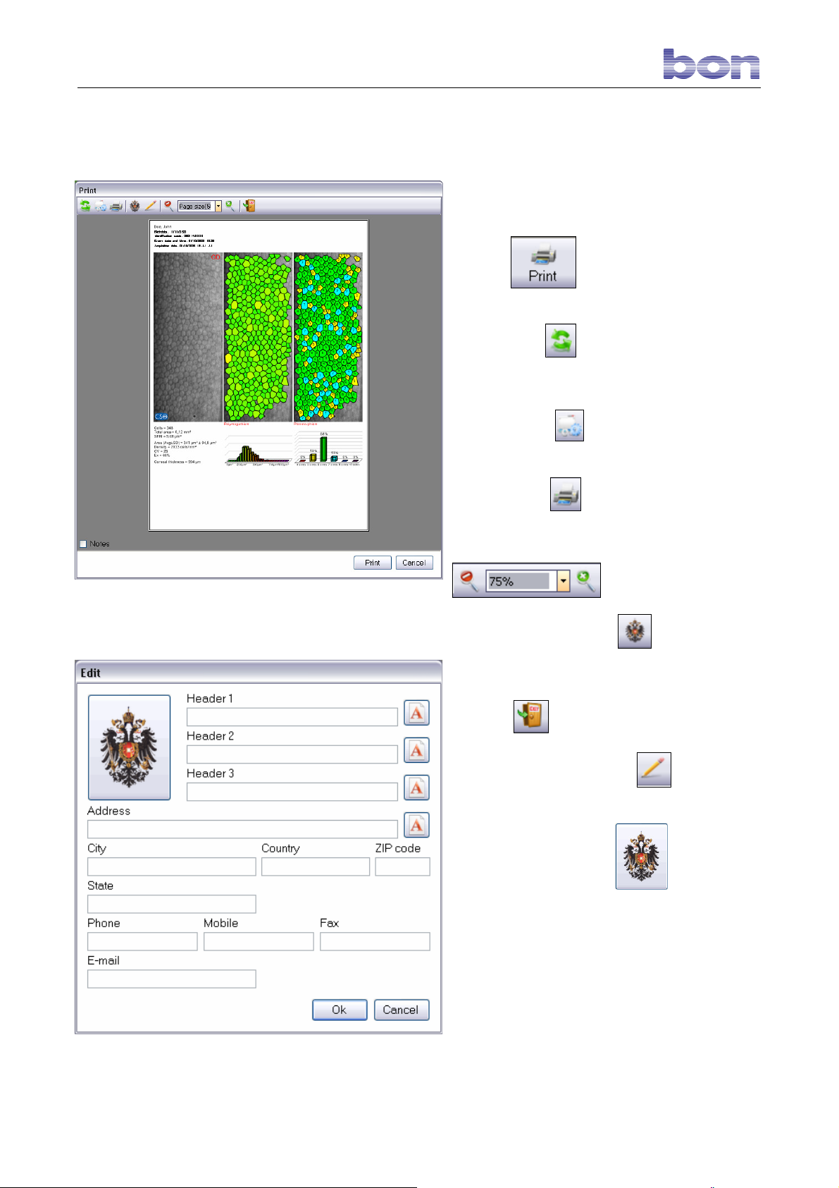
SEND DICOM: allows the user to send an
image in DICOM standard protocol.
8.24 PRINTING
Printing is possible only if a printer has been
connected to the PC.
Fig. 44 – Print window
Click the
screen to open the window shown in Figure 44.
- UPDATE: allows the user to update
the modifications in the print options and view
them immediately in a video preview.
- SETTINGS:
the print settings.
- PRINTER:
the printer to be used and the relative properties.
- ENLARGE – REDUCE PREVIEW:
SHOW/HIDE HEADING:
shows or hides the heading (if used) and relative
logo.
button on the processing
allows the user to change
allows the user to select
Fig. 45 – Edit company data
- ESC:
- EDIT COMPANY DATA:
window shown in Figure 45. This function allows
the user to insert the logo that will be displayed
on the printout by clicking
company data by filling in the relative fields.
Click OK to confirm.
To print after having viewed the preview, click
PRINT.
exits the printing screen.
opens the
and inserting
Page 34 of 45
Page 36
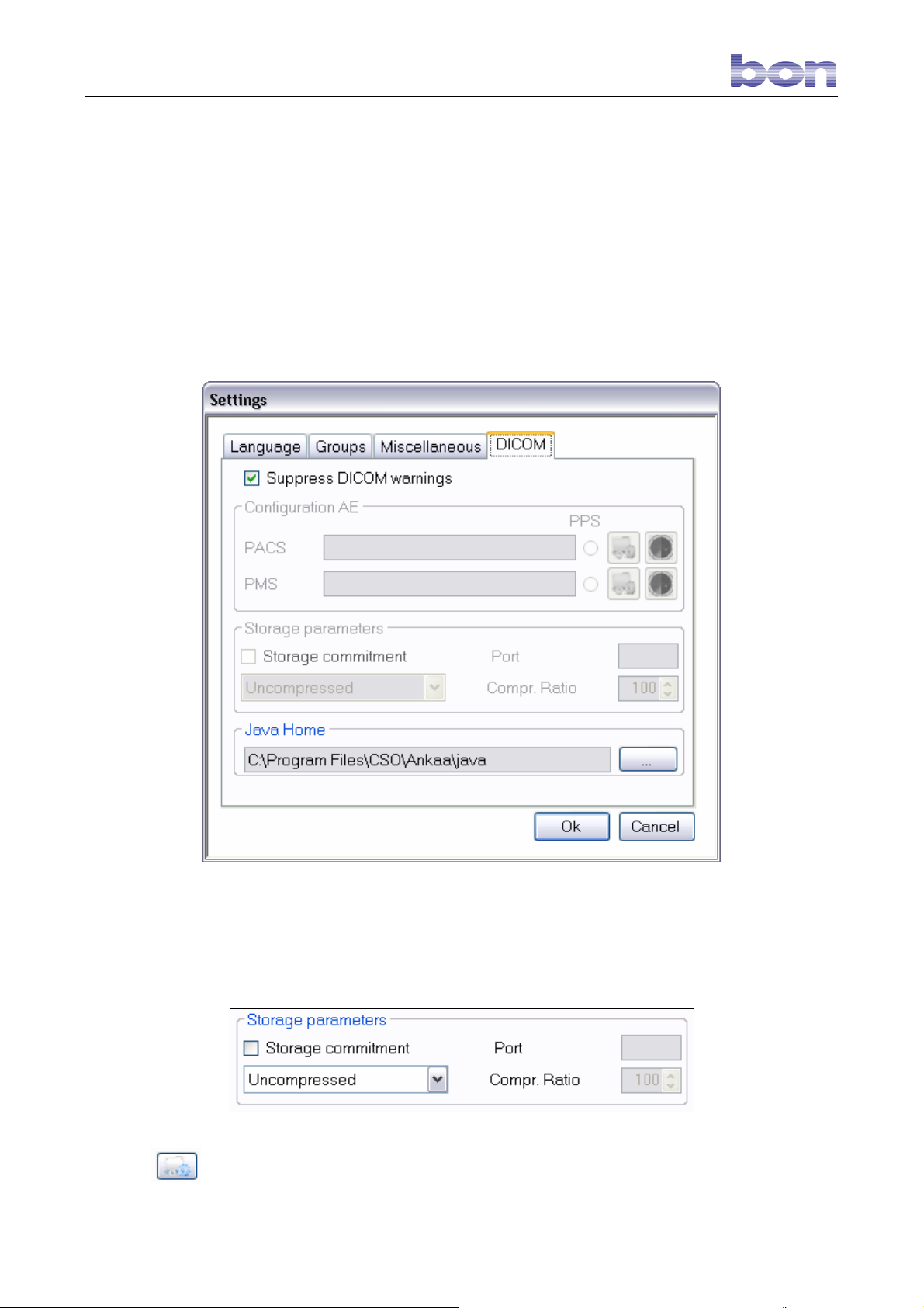
8.25 DICOM
DICOM is a medical computer standard, adopted by many health agencies and hospitals in all parts of the
world, which permits medical operators to exchange images and other information via computer systems
adopting this standard.
Deselect the “Suppress DICOM WARNING” box to show any errors that do not interfere with image
capture.
If DICOM is instead selected, the remaining menus must be used.
Fig. 46 – DICOM standard
Click the
PACS or PMS button to open the following windows:
Page 35 of 45
Page 37
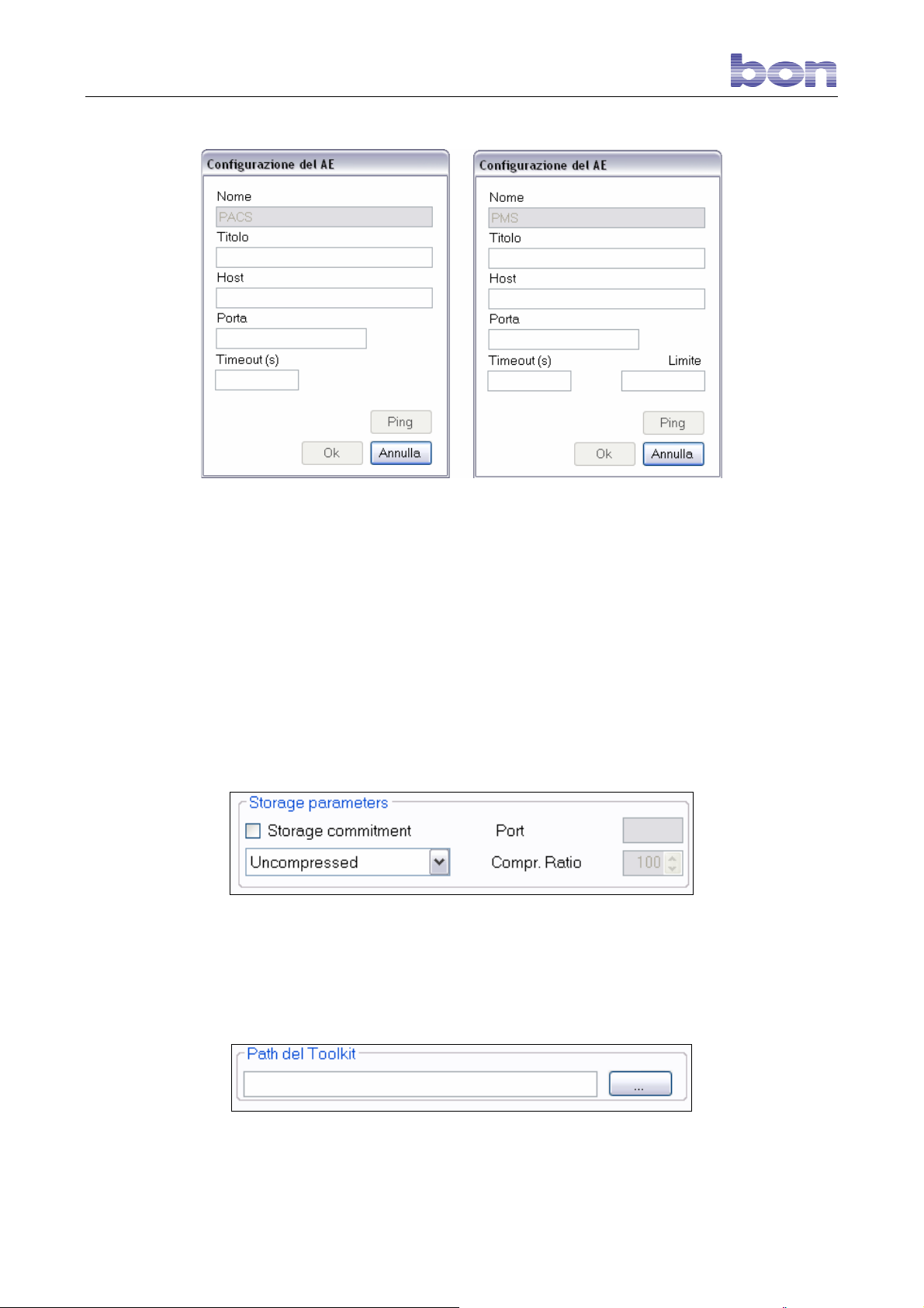
This window allows the user to identify the PACS system that will receive his information or the PMS system
from which information may be requested.
• In the relative fields, enter:
• Title: PACS/PMS ID.
• Host: PACS/PMS IP address.
• Port: PC port to which PACS/PMS is referred.
• Timeout(s): maximum waiting time before disconnecting a call.
• Limit: for PMS configuration only, identifies the maximum number of exams that may be received. If
the field is left blank, any number of exams may be received.
Click [OK] to save the settings as entered; otherwise click [Cancel].
Click [Ping] to initiate a call to the PACS/PMS system.
The user may specify several data storage options as save parameters:
• Storage commitment: select this box to receive a computer receipt for the data sent. Enter the
receiving PC in the Port field.
• Uncompressed/Lossless/Lossy: select this box to select the type of compression used for sending, in
a 5% to 100% ratio by 5% steps. The files are sent in the original, if you select uncompressed
format.
Page 36 of 45
Page 38

99.. OOPPEERRAATTIINNGG FFEEAATTUURREESS
The SP 02 Specular Microscope is the product of extensive research
conducted in collaboration with highly-accredited professionals in order
to ensure the very best in technological innovations, quality, and design.
The system incorporates a number of innovative solutions and therefore
offers several features that make it unique. Let us mention a few:
1) There is no photosensor or linear sensor on the return light path.
The image capture procedure is managed and implemented by
the software to guarantee greater reliability (through reduction in
the number of electronic components), lower production cost,
and greater operational versatility.
2) The CCD digital camera ensures high-contrast, high-quality
images.
3) The patient and exam files and captured images are stored in a
relational database to permit working with the acquired data at
any time following the examination.
4) The system supports data exchange via other applications in
Intranet/Internet environments: the message format is XML and
the SOAP protocol is used.
5) Future system expansions could include remote diagnostics and
automated examination with no need of operator assistance.
6) The cell-count software is completely automatic and processes
parameters that are not always supplied by other systems.
Software Features
The software can evaluate all the relevant data offered by the endothelial
analysis, including the following cell size variability summary data
(polymegathism):
• Number of cells in the area measured
• Cell density
• Mean cell area
• Standard deviation of the analyzed cells
• Coefficient of Variation
• Standard error of the mean (SEM)
• Histogram of cell size distribution
and the following cell morphology summary data:
• Hexagonal deviation (percentage of hexagonal cells)
• Form factor
• Histogram of cell form distribution.
The images are of excellent quality and cell count is fully automatic,
although manual editing operations can be performed when necessary.
This system permits automatically counting up to 400 cells with a single
capture: the high number of cells analyzed permits obtaining statisticallyrelevant and extremely repeatable data. The endothelial data analyses
and the images can be saved in an archive together with the patient’s
personal data. This archive may be integrated with the bon software
solutions for Corneal Topography and the Digital Slit Lamp.
Page 37 of 45
Page 39
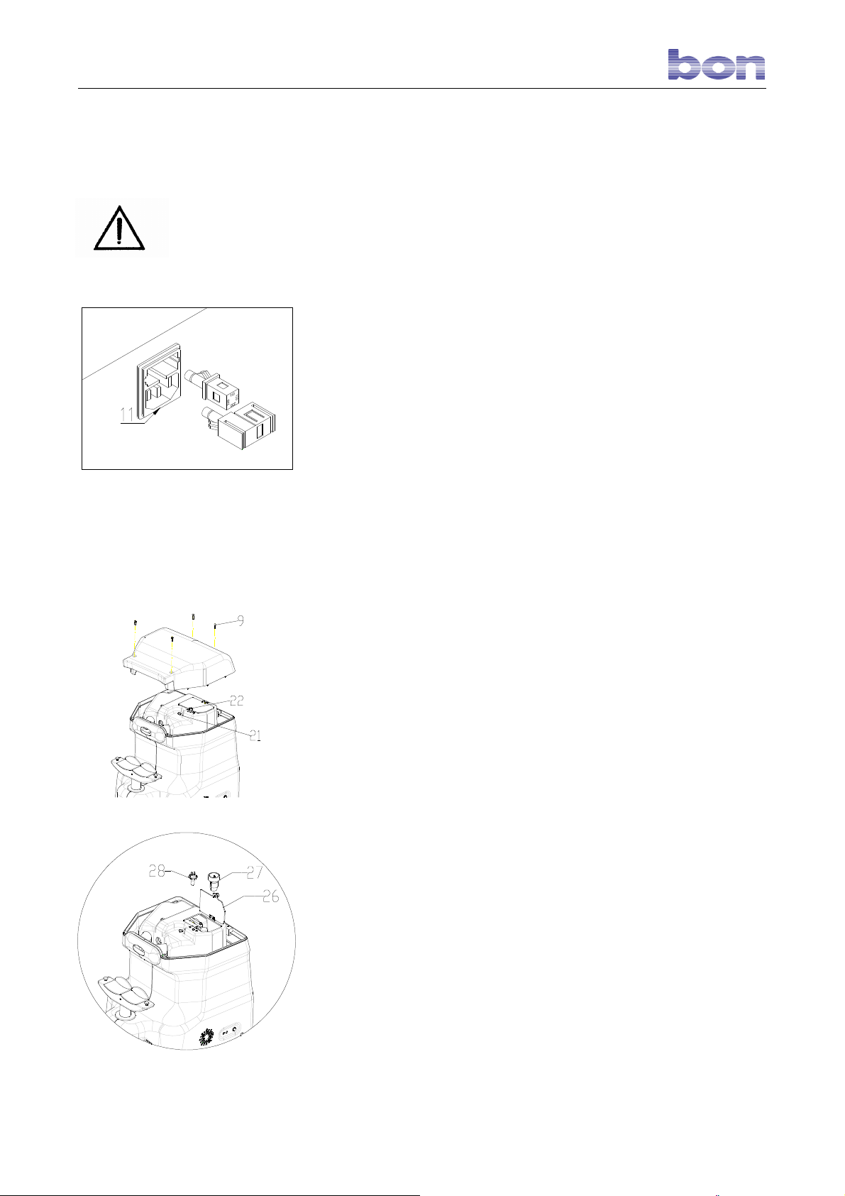
Replacing the line fuses
1100 RROOUUTTIINNEE MMAAIINNTTEENNAANNCCEE
The repairs illustrated below must all be performed only with the power
cord
disconnected from the line power socket. For any type of trouble
requiring repairs
different from those described below, contact your installation service.
34
Replacing the line fuses
10.1 REPLACING THE LINE FUSES
To replace the line fuses:
The line fuses are located on the rear of the transformer inside the
socket/voltage changer unit (11).
Before proceeding with replacement, disconnect power by
unplugging the
instrument power cord from the line socket.
Extract the voltage selector and remove the unserviceable fuses.
Replace the fuses with new fuses compatible with the line voltage
supply, as
reported on the data plate (13).
Replace the voltage changer unit.
Reconnect the plug to the line socket.
10.2 REPLACING THE MONITOR FUSE
The fuse is located in the fuse holder (15).
Before proceeding with replacement, disconnect power by
unplugging the
power cord from the line socket.
Rotate the fuse holder lock ring in the direction indicated and remove the
unserviceable fuse.
Replace the fuse with a good 0.315A fuse. Refer to the data plate (19).
Replace the fuse holder lock ring and tighten (turning in the opposite
direction). Reconnect the plug to the line socket.
10.3 REPLACING THE HALOGEN (28) AND/OR
FLASH (27) LAMP
To replace the lamps:
Before proceeding with replacement, disconnect power by
unplugging the
power cord from the line socket.
Unscrew the screws (9) and extract the optical head casing.
Unscrew screw (22) and open the lamp access door.
Replace the lamp: (28) 12V 30W halogen lamp, code 3008011230A, or
flash
lamp, code 30080801010.
Close the access door (26) and tighten the screw (22).
Replace the optical head casing and lock by tightening screws (9).
Reconnect the plug to the line socket.
Page 38 of 45
Page 40

10.4 PROTECTING THE INSTRUMENT FROM
DUST
When the instrument is not in use, it should be covered with the plastic
cover
supplied as standard equipment to protect it from dust. Any dust that
may
accumulate on the instrument should be periodically removed using a
very soft
cloth or a rubber ball air blower.
Page 39 of 45
Page 41

1111.. TTEECCHHNNIICCAALL DDEESSCCRRIIPPTTIIOONN
Photographic method:
Photographic field:
Measurement accuracy:
Video camera:
Flash:
Illumination for focusing:
Line voltage:
Fuses:
Power requirement:
Weight (instrument alone):
Size:
Non-contact
0.54 mm x 0.27 mm
±10 µm
CCD video camera
bon flash tube
12V 30W PG 22 alogen lamp
100V-120V ac ±10% 60 Hz
230V-240V ac ±10% 50 Hz
Line socket unit 5x20 mm 100/120V ⇒ 2x 2.5AT
230/240V ⇒2x 1.25AT
Monitor: 5x20 mm 1x 0.315AT
150 VA
18 Kg circa
420 mm (H) x 280 mm (L) x 380 mm (P)
11.1 CLASSIFICATION ACCORDING TO EN 60601 STANDARD
Type of protection against direct and indirect contacts: Class I
Level of protection against direct and indirect contacts: Tipe B
Level of protection against humidity: Common devices (no protection against
water
infiltration)
Method of sterilization: Disinfection of equipment
Level of protection in proximity to inflammable anesthetics
and/or detergents:
Use conditions: Continuous service
Level of electrical connection between instrument and
patient:
No protection
Device with applied parts
Page 40 of 45
Page 42
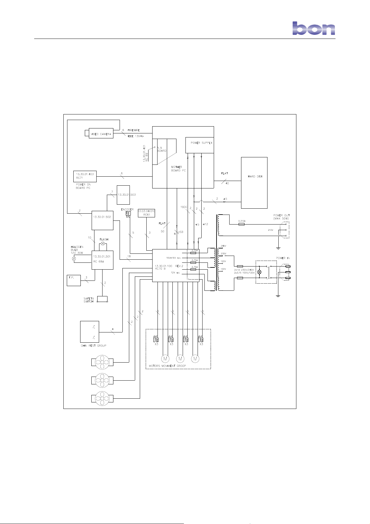
11.2 FUNCTION BLOCK DIAGRAM
On request, the manufacturer will supply diagrams, components lists, and detailed technical instructions for
use only by authorized personnel with prior training in maintenance and calibration.
bon Optic hereby declares that all the components making up their instruments are covered by insurance
and
full warranty for 24 (twenty-four) months.
Page 41 of 45
Page 43

11.3 DATA PLATE SYMBOLS
Read the instructions carefully
Type B protection against direct and
indirect contacts
Fuse
Mark of compliance with
relevant standards
Page 42 of 45
Page 44

1122.. LLIIAABBIILLIITTYY
CSO srl assumes responsibility for instrument compliance with European Directive 93/42/EEC and therefore
for its performance, safety, and reliability.
CSO srl would like to point out that all the components of the devices it produces are covered by insurance
and full warranty for 24 (twenty-four) months.
CSO srl nevertheless declines said responsibility if:
installation and start-up are not performed in compliance with the instructions and precautions set forth in
this manual.
the instrument is used in ways not in accordance with the instructions and precautions set forth in this
manual.
accessories and/or spare parts not supplied or recommended by CSO srl are used.
repairs and safety checks are not performed only by competent, qualified, and suitably-trained personnel
authorized by CSO srl.
the electrical system of the instrument installation site does not comply with CEI standards and the
pertinent laws and regulations in force.
CSO srl also declines any and all responsibility for direct or indirect consequences or damage to persons
and/or things deriving from improper use of the instrument and/or from erroneous clinical evaluation of
information derived from its use.
1133.. WWAARRRRAANNTTYY AANNDD TTEECCHHNNIICCAALL AASSSSIISSTTAANNCCEE
CSO srl guarantees this product for a period of 24 months from date of invoice. This warranty includes
replacement, at CSO, of components and materials as well as relative labor. Shipping costs are at the
customer’s expense.
Parts subject to wear and/or deterioration during normal use (for example, lamps and fuses) and parts
damaged by improper use or inadequate maintenance are not covered by warranty.
CONDITIONS NOT INCLUDED UNDER WARRANTY
Repair of damages caused by natural catastrophes, mechanical shock (dropping, crushing, etc.), defects
in the user’s electrical system, negligence, improper use, and/or maintenance/repairs performed using
non-original materials and/or by persons not authorized by CSO srl
Any type of improper use or use not specifically intended by the manufacturer.
CSO srl declines responsibility for any interruption or inefficiency in service due to causes or circumstances
beyond their control. The customer shall in no case have any right to compensation for damages suffered as
a consequence of the unavailability of the instrument.
To request technical assistance with maintenance, contact a technical assistance center or directly contact:
CSO srl
Costruzione Strumenti Oftalmici
Via degli Stagnacci, 12/E
50010 Badia a Settimo - Scandicci , Florence ITALY
Page 43 of 45
Page 45

1144.. CCEERRTTIIFFIICCAATTEESS // SSTTAATTEEMMEENNTTSS OOFF CCOOMMPPLLIIAANNCCEE
CSO srl - Costruzione Strumenti Oftalmici with headquarters in Via Degli Stagnacci 12/e – 50010 – Badia a
Settimo – Florence – Italy, manufacturers of the medical electrical system denominated
SP/02 Specular Microscope
in the persons of its legal representatives Sergio Mura and Giuseppe Matteuzzi,
who assume full personal liability for the following,
HEREBY CERTIFY
that the above-mentioned product complies fully with the following EU Directive, including the latest
amendments, and with the relative national implementing legislation:
DIRECTIVE 93/42/EEC “MEDICAL DEVICES ” of 14 June 1993
that the following harmonized standards were applied:
EN 60601-1 “Medical Electrical Equipment – Part 1: General Requirements For Safety," as
amended, corresponding to Italian standard CEI 62-5 – 1991 edition – record no. 1445.
EN 60601-1-2 “Medical Electrical Equipment – Collateral Standard: Electromagnetic
Compatibility,” corresponding to Italian standard CEI 62-50 – 2001 edition.
EN 60601-1-1 “Medical Electrical Equipment – Collateral Standard: Safety Requirements for
Medical Electrical Systems,” as amended, corresponding to Italian standard CEI 62-51 – 1994
edition – Record no. 2308.
UNI EN ISO 15004 “Ophthalmic instruments. Fundamental Requirements and Test Methods.”
2000 edition.
that the product is a Class I device as per Annex IX of the above-cited Directive.
that the instrument is marketed with the mark.
that the complete reports of the tests carried out on a random sample from series production and the rest
of the technical and quality assurance documentation (as called for by Annex VII of Directive 93/42/EEC)
are kept in the CSO srl Technical Office files.
Signature of Legal Representative
_____________________________
Page 44 of 45
Page 46

1155.. RREEFFEERREENNCCEE SSTTAANNDDAARRDDSS
The following reference standards were applied in design, production, and testing of the product:
EU Directives
DIRECTIVE 93/42/EEC “MEDICAL DEVICES ” of 14 June 1993.
DIRECTIVE 2002/96/EC “Waste Electrical and Electronic Equipment (WEEE).”
Standards concerning Quality Management Systems
UNI EN ISO 9001:2000 “Quality Management Systems – Requirements.”
UNI EN ISO 13485:2004 “Medical Devices – Quality Management Systems - Clinical
Requirements for Regulatory Compliance.
Technical Standards
EN 60601-1 “MEDICAL ELECTRICAL EQUIPMENT – PART 1: GENERAL REQUIREMENTS FOR
SAFETY" as amended, corresponding to Italian standard CEI 62-5 – 1991 edition – record no.
1445.
EN 60601-1-2 “MEDICAL ELECTRICAL EQUIPMENT – Collateral Standard: Electromagnetic
Compatibility,” corresponding to Italian standard CEI 62-50 – 2001 edition.
EN 60601-1-1 “MEDICAL ELECTRICAL EQUIPMENT – Collateral Standard: Safety
Requirements for Medical Electrical Systems,” as amended, corresponding to Italian
standard CEI 62-51 – 1994 edition – Record no. 2308.
UNI EN ISO 15004 “Ophthalmic instruments. Fundamental Requirements and Test Methods.”
2000 edition.
UNI EN ISO 14971:2004 “Risk Management for Medical Devices.”
The registered trademarks are property of the respective trademark owners.
Costruzione Strumenti Oftalmici
Via degli Stagnacci, 12/E
50010 Badia a Settimo - Scandicci , Florence ITALY
Rev. 4 date 23/09/09
CSO srl
Page 45 of 45
 Loading...