

Page 1
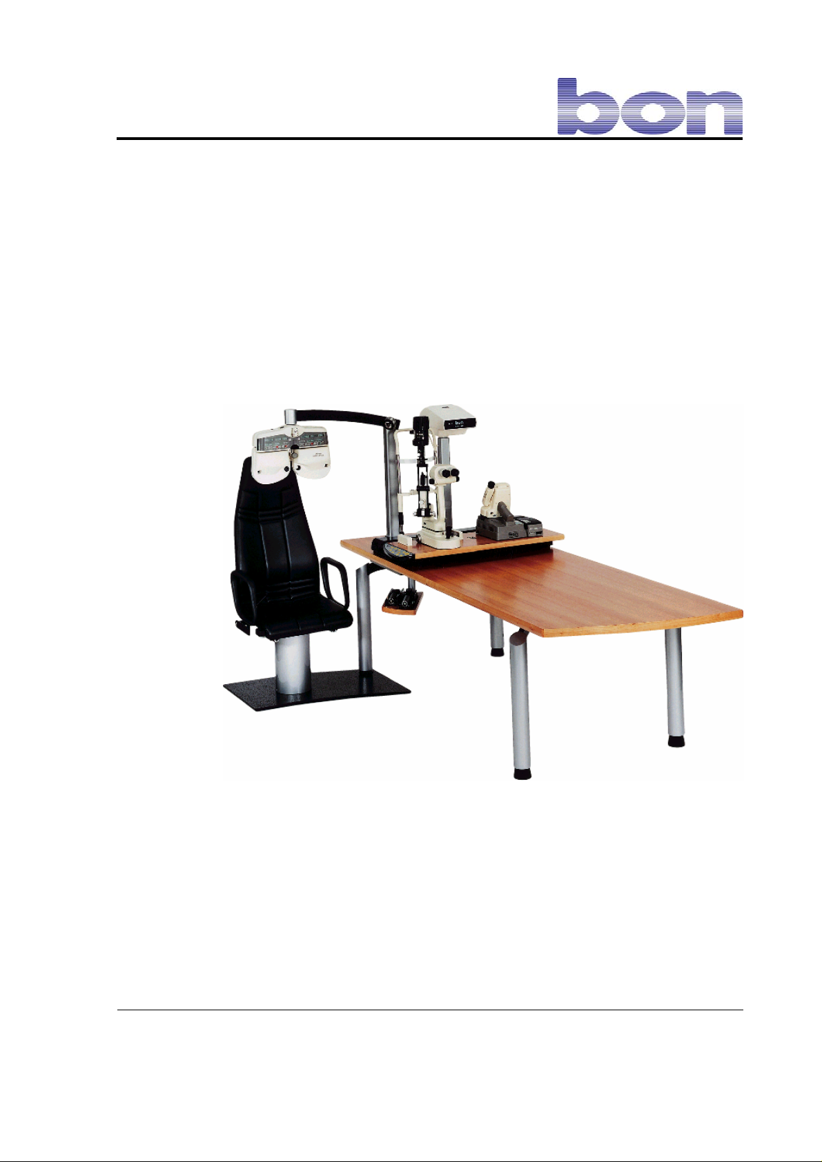
Instruction manual
bon E-30
GA bon E-30 Rev 1.1 E 260406
PO Box 32 26
23581 Lübeck
Stellmacherstraße 14
D-23556 Lübeck
bon Optic Vertriebsgesellschaft mbH – managing director: H. Jochen Kaber – HR Lübeck, HRB 3475 – VAT No. 161662634
Phone: 0451/ 80 900-0
Fax: 0451/ 80 900-10
E-Mail: [email protected]
Internet: www.bon.de
Sparkasse zu Lübeck
(Sort code 230 501 01) Acc.No. 1 014 885
Swift / BIC: HSHN DE H1 SPL
IBAN: DE 2305 0101 0001 0148 85
Commerzbank Lübeck
(Sort code 230 400 22) Acc.No. 0 107 755
Postbank Hamburg
(Sort code 200 100 20) Acc.No. 409 22-204
Page 2

DS 2/27
Page 3

Contents
1 Introduction.....................................................................................................4
2 Important information.....................................................................................5
2.1 Information about the device.............................................................................. 5
2.2 Application and classification ............................................................................. 5
2.3 Liability ............................................................................................................... 5
2.4 Scope of delivery................................................................................................5
3 Safety instructions..........................................................................................6
4 Description of device...................................................................................... 7
5 Setting-up, assembly and repair....................................................................8
6 Operation.........................................................................................................9
6.1 Controls.............................................................................................................. 9
6.2 Initial start-up....................................................................................................10
6.3 Control of components..................................................................................... 10
6.3.1 Exchangeable table.........................................................................................................10
6.3.2 Phoropter arm .................................................................................................................10
6.3.3 Examination chair............................................................................................................11
6.3.4 Tretractable equipment tray for hand-held devices .........................................................11
6.3.5 Spotlight ..........................................................................................................................11
6.3.6 Ambient light....................................................................................................................11
6.3.7 Focussing lights, Maddox cross, extra buttons/keys .......................................................11
6.4 Programming the ambient light ........................................................................ 12
7 Setup..............................................................................................................13
7.1 Exchangeable table and phoropter arm........................................................... 13
7.2 Standby............................................................................................................ 13
7.3 Curtain control.................................................................................................. 14
7.4 Fix 1, Fix 2, Aux 1, Aux 2 ................................................................................. 15
7.5 Supply voltage of devices................................................................................. 15
8 Maintenance and care...................................................................................17
8.1 Care.................................................................................................................. 17
8.2 Maintenance.....................................................................................................17
8.3 Do-it-yourself repairs........................................................................................ 17
8.3.1 Changing the fluorescent medium of the work lamp........................................................17
8.3.2 Changing batteries/initialising the remote control............................................................17
8.3.3 Changing a fuse..............................................................................................................18
9 Guarantee ......................................................................................................20
10 Circuit plans/technical data..........................................................................21
Appendix: EC Declaration of conformity
3/27
Page 4
1 Introduction bon E-30
1 Introduction
Dear customer
Thank you for purchasing our refraction unit bon E-30. Please read the operating instructions
carefully before using the system. Keep these instruction manual safe for future use. Please
observe the safety instructions.
If you have any further questions, please contact our customer helpline.
Meaning of the symbols in the operating instructions
Caution! Please observe safety instructions with this symbol to prevent
personal danger or damage to property.
Important! Indicates particularly important information to maintain the
function of the device/system or to extend its life.
This publication may not be copied or transferred without prior agreement from bon Optic.
bon Optic reserves the right to make changes in the interest of technical development. These operating
instructions are not subject to updating.
4/27
Note! Indicates information for correct use so that errors may be avoided.
Page 5

2 Important information bon E-30
2 Important information
Manufacturer: bon Optic Vertriebsgesellschaft mbH · Stellmacherstr. 14 · D- 23556 Lübeck
2.1 Information about the device
Name of device: bon E-30
2.2 Application and classification
The refraction unit bon E-30 serves as a carrier to which ophthalmological devices such as
slit lamps and ophthalmometers can be attached. These devices may be adjusted in front of
the patient who came for a medical examination.
The refraction unit bon E-30 is a Class 1 non-invasive, active medical device in accordance
with the classification regulations of Directive 93/42/EWG on medical devices (MDD).
2.3 Liability
The refraction unit is manufactured according to the current technical status and the
recognised safety regulations and is tested in accordance with strict quality criteria. bon Optic
accepts liability for the safety, reliability and performance of the device if
installation and any changes or repairs have been carried out by a person authorised
by bon Optic to do so.
the power supply to which the device is connected corresponds to the national
legislation.
the device is operated in accordance with these operating instructions.
the operator complies to the ordinance on the Operation of Medical Devices
(MPBetreibV).
If the system is asembled, changed or repaired by an unauthorised person, if it is improperly
maintained or not used as described in 2.2, the manufacturer is no longer liable.
2.4 Scope of delivery
1 x refraction unit bon E-30 as per agreed equipment
1 x remote control
1 x mains cable (for equipment types without wall terminal box)
1 x instruction manual
5/27
Page 6

3 Safety instructions bon E-30
3 Safety instructions
Please follow the legal requirements on accident prevention and observe the following safety
instructions!
Setting-up and assembly:
The refraction unit should not be assembled and operated in damp rooms.
Ensure that the device is on a level and stable surface during assembly.
The mains voltage must be the same as stated on the product label.
The max. weight-bearing capacity of the exchangeable table (3) is 30 kg/device
station.
Operation:
Do not expose the system to extremes of temperatures. It is recommended that the
product be used at temperatures of between +10° C and +40° C.
Avoid dropping or splashing water on the device.
The max. weight-bearing capacity of the examination chair (7) of 170 kg must not be
exceeded.
Ensure that the patient keeps his/her hands away from the exchangeable table.
There is a risk of pinching body parts!
The examination chair is not suitable for continuous operation. After continuous
operation of 60 seconds, wait at least 9 minutes for the device to cool down.
Ensure that during operation the phoropter arm (8) does not collide with the patient’s
head.
If the working place lamp (1) is used for a long time span, the housing will get hot.
You could be burned!
Other information:
Do not pull on the power cable in order to remove the plug from the socket (this
applies to equipment types without wall terminal boxes).
Run all cables properly to prevent people from stepping on tem or tripping over them.
Ensure that no damage occurs to the cable (e.g. sharp edges, excessive heat).
Before doing any repairs, maintenance or installation work always pull out the mains
plug.
6/27
Page 7
4 Description of device bon E-30
4 Description of device
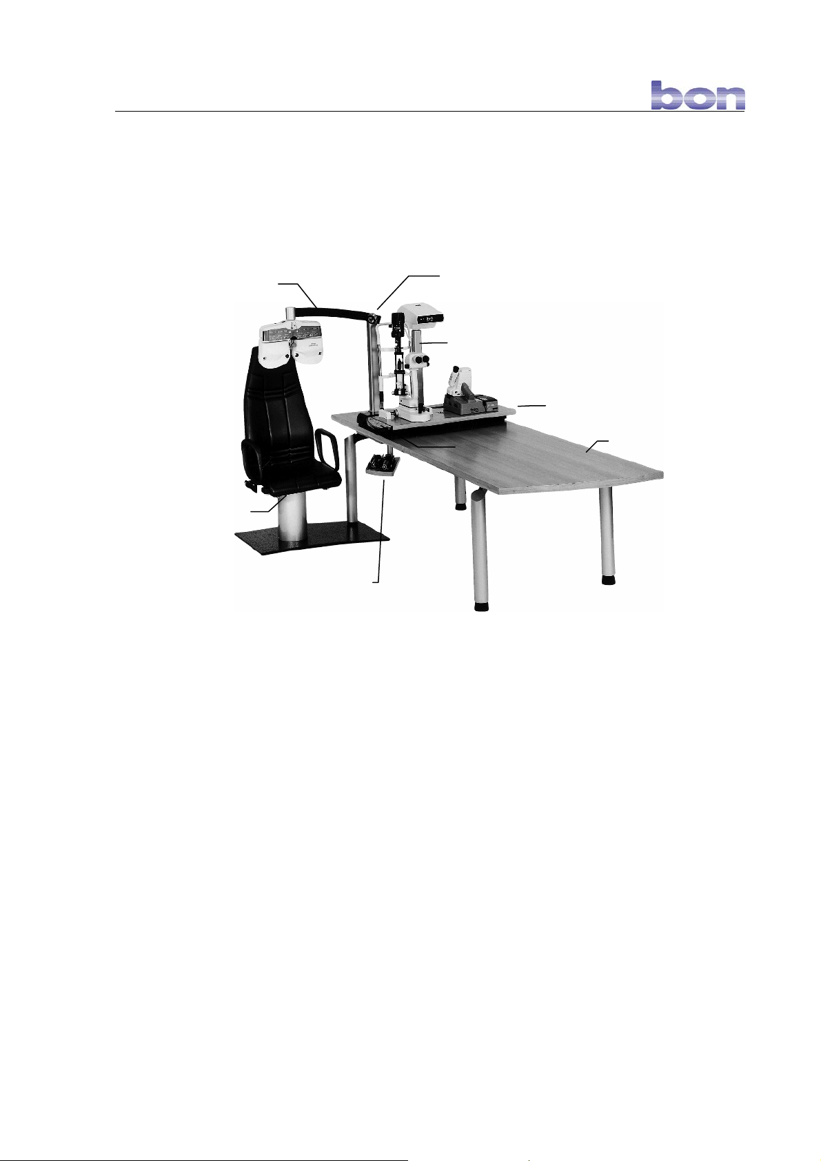
Main components (max. number of components)
(8) Phoropter arm
(7) Examination chair
(6) Retract. equipment tray for
small/hand-held devices
Characteristics of refraction unit:
- Exchangeable table (3) driven by electric motor for positioning [medical] devices in front of
the patient.
- Phoropter arm (8) driven by electric motor for the positioning of the phoropter in front of the
patient.
- Examination chair (7) with electric lifting motor and with hinged left armrest and
horizontally adjustable chair.
- Tretractable equipment tray (6) with automatic switch-off facility for these devices.
- Projector column (2) with recess for optotype projector.
- Reading illumination (1).
- Large-surface work table (4)
- Control panel (5) to control the exchangeable table, phoropter arm, etc.
- Control is also possible with remote control.
Electrical connection of refraction unit is by a shockproof socket or a wall terminal box.
(1) Spotlight
(2) Projector column
(5) Control panel
(3) Exchang. table
(4) Work table
7/27
Page 8

5 Setting-up, assembly and repair bon E-30
5 Setting-up, assembly and repair
Expert staff from bon Optic or your distributor will set up and assemble the refraction unit.
Changes or repairs to the refraction unit may only be carried out by persons authorised by
bon Optic. Medical devices that are linked to the electricity supply of the refraction unit must
be shown to comply with DIN EN / IEC specifications. All configurations must meet the
requirements of the DIN EN 60601-1-1 (IEC 601-1) standard. Non-electrical devices that are
connected to the unit must not affect the safety level of the unit. Changes to the refraction
unit must not endanger patients, users and the surroundings.
Repairs that can be carried out without a technician can be found in Chapter 8:
Maintenance and care
8/27
Page 9
r
r
6 Operation bon E-30
6 Operation
6.1 Controls
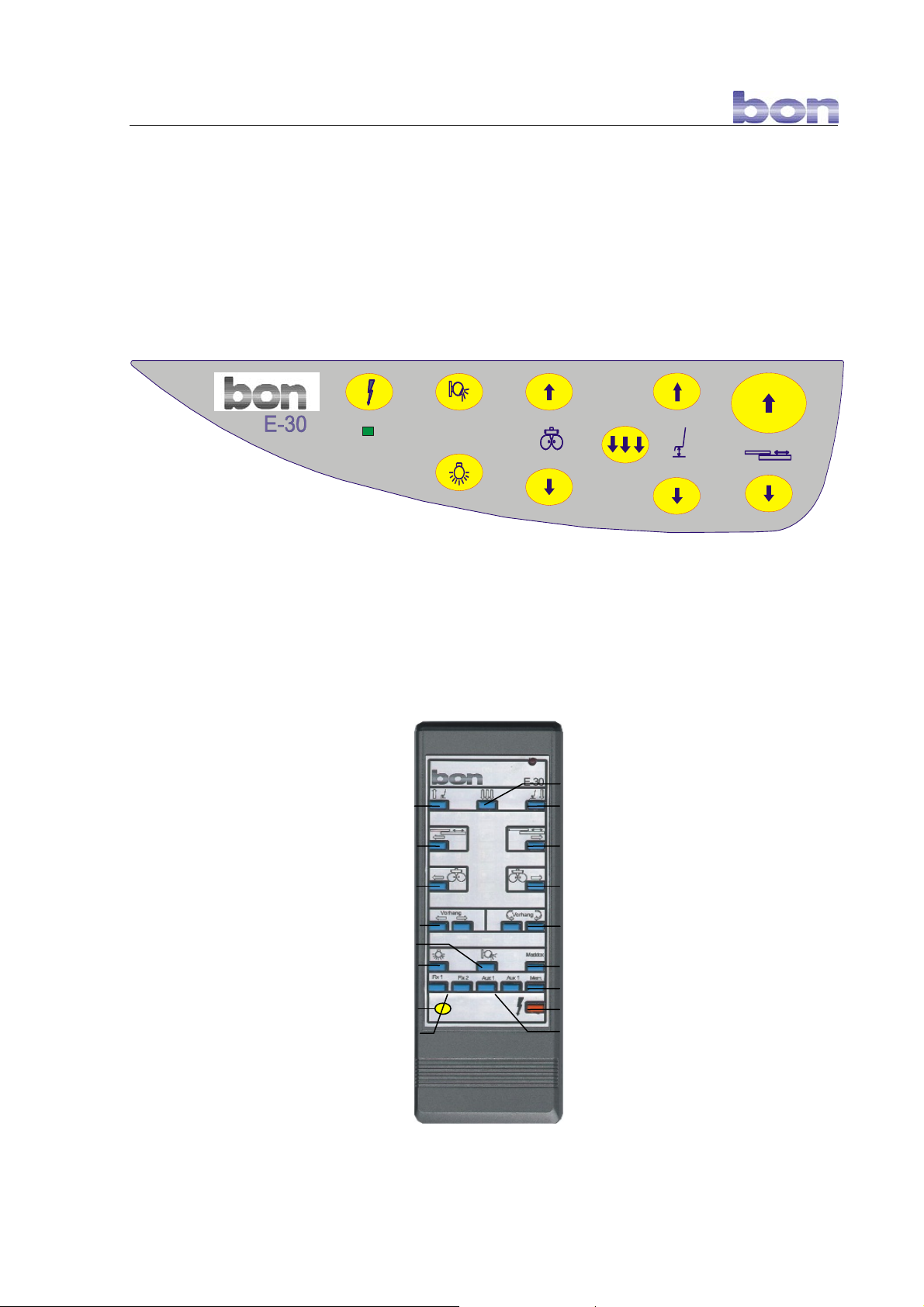
The refractions unit may either be controlled by means of the operating keyboard on the
exchangeable board or by the remote control.
1 2
6
7
3 4
9
8
10
5
11
Abbildung 6-1: Control panel
1 Switch-on/off unit 5 Exchangeable table backward
9 Chair down completely
2 Dimmer spotlight 6 Pilot lamp (operation) 10 Chair down
3 Phoropter backward 7 Dimmer for ambient light 11 Exchang. table forward
4 Chair up 8 Phoropter forward
Chair down completely
Chair downChair up
Exchangeable table backward Exchangeable table forward
Phoropter backward Phoropter forward
Curtain 1 up/down
Spotlight dimme
Ambient light dimme
Control of focusing lights
Prog.
Curtain 2 up/down
Maddox cross on/off
Save button/key
Examination unit on/off
Control for other devices
9/27
Abbildung 6-2: Remote control
Page 10
6 Operation bon E-30
6.2 Initial start-up
a) without wall terminal box.
Plug the supplied power cable of the refraction unit into the mains socket. The socket of the
refraction unit is on the back table leg.
b) with wall terminal box.
Activate the on-/off-switch on the wall terminal box.
- Press the on/off button on the control panel or on the remote control in order to switch on
the refraction unit.
- The green pilot lamp on the control panel lights up.
- The refraction unit is now ready for operation.
6.3 Control of components
6.3.1 Exchangeable table
Press the buttons/keys on the operating panel to
zurü
move the exchangeable table forward or
ck
backward. Alternatively, you may also operate the
exchangeable table by using the remote control.
Ensure that while the exchangeable table is moving
patients keep their hands away from the
vor
exchangeable table.
There is a risk of pinching body parts!
Manually move the exchangeable board to switch from position 1 to position 2. Depending on
the position, the corresponding device will be switched on.
On the side under the work table there is a potentiometer for adjusting the brightness (for
programming see chapter 7.5) of the table devices.
6.3.2 Phoropter arm
backw
Press the buttons/keys on the operating panel to
ard
move the exchangeable table forward or
backward. Alternatively, you may also operate
the exchangeable table by using the remote
control.
Ensure that the phoropter will not collide with the
patient’s head. There is a risk of getting injured.
forwar
d
The exchangeable table and the phoropter arm may never me moved forward
simultaneously. If, for example, you want to bring the phoropter arm into the working position
although the exchangeable table has already been extended, the system will first bring back
the exchangeable table into the zero position.
10/27
Page 11
6 Operation bon E-30
6.3.3 Examination chair
Press the buttons/keys on the operating panel to
move the examination chair forward or backward.
up
Alternatively, you may also operate the examination
chair by using the remote control.
down
With the
button/key, the examination chair will move down in its final position.
There is the option to install a foot switch for the functions up/down. For this purpose, please
contact our customer service.
6.3.4 Tretractable equipment tray for hand-held devices
Hand-held devices will switch on automatically when they are picked up from the tretractable
equipment tray.
6.3.5 Spotlight
Press the
button/key on the control panel in order to switch on/off the spotlight.
Pressing this button down for some time will activate the dimmer function. The cycle
changing from light to dark and back again to light will be repeated as long as the button/key
is pressed down. Alternatively, you may also operate the spotlight by using the remote
control.
6.3.6 Ambient light
Press the
button/key on the control panel in order to switch on/off the ambient
light. Pressing this button/key down for some time will activate the dimmer function. The
cycle changing from light to dark and back again to light will be repeated as long as the
button/key is pressed down. Alternatively, you may also operate the ambient light by using
the remote control.
We advise against using dimmers for fluorescent lamps.
6.3.7 Focussing lights, Maddox cross, extra buttons/keys
By pressing the buttons Fix 1 and Fix 2 of the remote control, the focusing lights are
controlled, and pressing the maddox button will switch on/off the maddox cross provided that
these lamps have been installed to the optional wall terminal box. You may, however, also
control other devices by using these buttons.
In addition, there are the extra keys Aux 1 and Aux 2 for controlling other devices.
11/27
Page 12
6 Operation bon E-30
6.4 Programming the ambient light
You may predefine the ambient light for 6 different operating positions. If the desired
operating positions has been selected (e.g. exchangeable table has been extended), the
programmed level of ambient light will be selected automatically.
You may define the following operating positions for the ambient light:
No Exch. table,
pos. 1
1 x x x x x
2
3 x
4 x x
5 x x x
6 x x x x
z
x = inactive
Programming steps:
1. Bring the examination unit into the desired operating position
(No. 1-6 of table).
Exch. table,
pos. 2
x x x x
z
z = active
Phoropter arm Hand-held
device 1
x x x
z
x x
z
Hand-held
device 2
x
z
2. Select the desired level of brightness for the ambient light by pressing the
button on the control panel or using the remote control.
3. Press down the [Mem.] button on the remote control until you hear a signal tone.
4. The selected brightness for the ambient light has now been memorised for this
operating position.
Deleting the programming:
1. Bring the examination unit into the desired operating position
(No. 1-6 of table).
2. Press down the [Mem.] button on the remote control until you hear two short signal
tones.
3. The programmed ambient light level for this operating position has now been deleted.
By pressing the ambient light button, the brightness level may be changed any time. This will
not affect the memorised value. However, if you switch off the ambient light, the automatic
ambient light control will be deactivated. In order to re-activate the automatic ambient light
control, the ambient light must first be switched on again.
12/27
Page 13

7 Setup bon E-30
7 Setup
If you want to start the set-up process, press the following key combination on the remote
control:
[Fix 2] → [Maddox] → [Maddox] → [Fix 1]
You will hear a long and two short signal tones. To terminate the setup, you simply switch off
the unit by pressing the
7.1 Exchangeable table and phoropter arm
Upon delivery, the refraction unit will be programmed with these defaults. A setup is therefore
only necessary, if you want different final positions or if the programming has been lost.
Setting the position defaults for the exchangeable table and the phoropter arm:
1. Start the setup (cf. chapter 7).
2. Move the exchangeable table or the phoropter arm by using the remote control or the
control panel into the desired final position (e.g. exchangeable table into operating
position).
3. Press the [Mem.] button on the remote control until you hear a signal tone.
4. Press the same button you have used for bringing the exchangeable table or the
phoropter arm into the desired position.
5. Memorization was successful if you hear a long signal tone.
Repeat steps 2 to 5 for the other positions.
button.
7.2 Standby
The refraction unit may be switched off automatically after its last operation after a set time
has elapsed.
1. Start the setup (cf. chapter 7).
2. Press the
the number of signal tones will increase. The following times for switching off the
refraction unit can be set:
Signal tones Switch-off time
1 15 min.
2 30 min.
3 1 h
4 2 h
5 4 h
6 8 h
7 off
3. To save the value, switch off the refraction unit.
13/27
button until you hear a signal tone. If you press the button repeatedly,
Page 14
7 Setup bon E-30
7.3 Curtain control
By using the wall terminal box literally all kinds of curtain mechanisms and vertical blinds can
be controlled. There are 5 different control options:
Mode Function
1 Operation by depression of key; function is maintained as long as the key is pressed.
2 Switching operation (Relay switches to lock position).
3 Combination from mode 1 and mode 2:
If the key/button is pressed longer than 3 seconds, the relay will switch into lock
position.
4 Automatic control for curtains/systems with limit switches:
In this mode,
a) the running time
b) the waiting time (optional)
for the curtain are set. This makes sense as, for example, the curtain should not always
completely open and close in between two examination.
Application:
1. For first examination, the exhangeable table is moved forward. → Curtain closes when it reaches limit
switch.
2. Exchangeable table is moved backward. → Curtain remains closed (waiting time, for example 1.5 minutes)
3. Hand-held device is removed for second examination.
4. Hand-held device is re-inserted into system → Curtain opens after the set running time of 1.5 minutes has
elapsed.
5 Automatic control for curtains/systems without limit switches:
Just as for mode 4, the running time applies to opening and closing of curtain.
Select the running time for the curtain so that it is closed once the running time has
elapsed.
There are two pairs of keys/buttons on the control for
a) one curtain with two stepper motors or
b) two curtains with one stepper motor.
Both pairs of keys/buttons can be programmed independently. If, however, both pairs of
keys/buttons are in modes 4 or 5, the programmed times will apply to both pairs of
keys/buttons.
LLP RLP LRP RRP
Start the setup (cf. chapter 7).
In order to set the desired mode (1-5), press the left key/button (LLP or LRP) of the selected
key/button pair.
The number of signal tones and the corresponding mode are the same. To save the value,
switch off the unit.
The running time (1 to 7 seconds) is set by pressing the key/button RRP. The number of
signal tones indicates the number of [set] seconds. To save the value, switch off the unit.
The delay (from 0 to 1.5 minutes) is set by pressing the RLP key/button (increase by 15second increments). Here one signal tone means no delay, and 7 tones correspond to 1.5
minutes. To save the value, switch off the unit.
14/27
Page 15

7 Setup bon E-30
7.4 Fix 1, Fix 2, Aux 1, Aux 2
You may change the functions of key/buttons Fix 1, Fix 2, Aux 1 und Aux 2 from manual to
automatic operation.
1. Start the setup (cf. chapter 7).
2. Press the corresponding key/button [Fix 1], [Fix 2], [Aux 1] or [Aux 2] until you hear
one or two signal tones.
1 x signal tone = Function is carried out by depression of key [manually].
2 x signal tone = Function is carried out by automatic switching.
3. To save the value, switch off the refraction unit.
7.5 Supply voltage of devices
The control system of the refraction unit can produce a set supply voltage for the installed
devices.
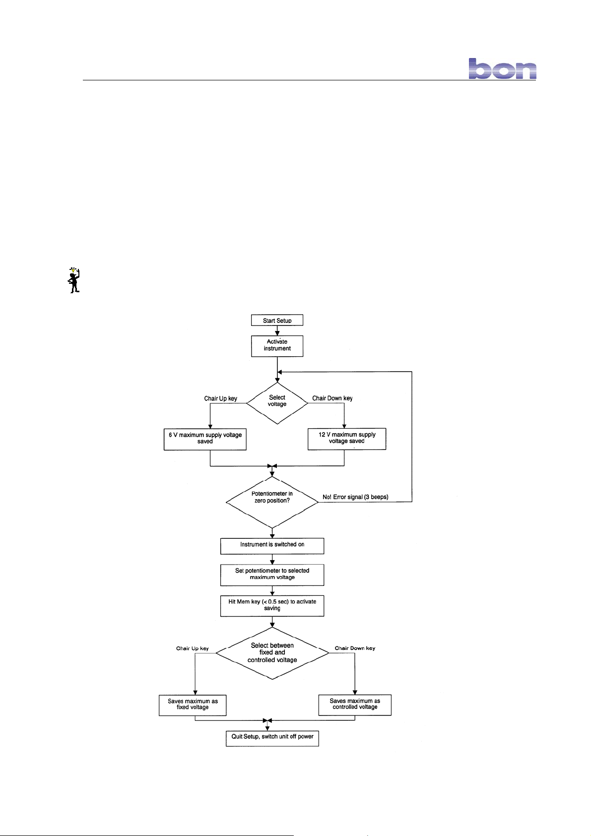
Ensure that your device is connected properly to the control system of the refraction unit.
Measure/check the supply voltage with a voltmeter directly on the power-consuming device.
Programming steps:
1. First reset the potentiometer (as far to the left as it will go). You find the potentiometer
on the side underneath the exchangeable table.
2. Start the setup (cf. chapter 7).
3. Move the desired device into the operating position (e.g. pick up hand-held device
from tretractable equipment tray).
4. Select the supply voltage
6 V by pressing the button/key “chair up“
12 V by pressing the button/key “chair down“
on the remote control or on the control panel. For intermediate values of 3.5 volt or 8
volt, select the next highest voltage value. You will hear a short signal tone to
acknowledge your setting.
If the potentiometer has not
abortion of the programming will be followed by 3 short tones. Start with step 1.
5. Slowly increase the supply voltage by turning up the potentiometer until you reach the
desired supply voltage. Check the voltage with your voltmeter.
Ensure that you do not destroy the power-consuming device by applying an excessvoltage.
6. To save the set voltage, press the [Mem.] key/button on the remote control.
7. You can now determine whether the set voltage should be saved as fixed voltage or
as control voltage.
been reset, you will receive an error message. The
15/27
Page 16
7 Setup bon E-30
a) Press the “chair up“ key/button for selecting a fixed voltage, i.e. the set voltage will
be automatically set upon activating the device irrespective of the position the
potentiometer is in at the moment,
or
b) Press the “chair down“ key/button to select a regulated voltage, i.e. a set voltage
can be regulated with the potentiometer (maximum is reached, if turned to the right as
far as it will go).
The setting has been successful if you hear a long signal tone.
8. To save all values, switch off the refraction unit.
The programming process may be interrupted any time by switching off the refraction
unit. If the programming process is not finished, the parameters will not be saved.
16/27
Page 17
8 Maintenance and care bon E-30
8 Maintenance and care
8.1 Care
Clean the refraction unit with a clean and damp chamois leather. Do not use any abbrasive
or aggressive cleaning fluids!
8.2 Maintenance
The refraction unit if used appropriately does not require any regular maintenance.
For repairs or in the event of technical problems please contact the customer care team at
bon Optic.
8.3 Do-it-yourself repairs
You may do the following repairs yourself:
8.3.1 Changing the fluorescent medium of the work lamp
Used lamp: Halogen reflector lamp with reflector and safety glass
(12 V / 20 W), base GU 5.3
1) Before doing any repairs, always pull out the power plug.
2) To avoid burns, always wait until the lamp has cooled down before replacing it.
3) Pull out the lamp from the lamp holder.
4) Insert the new lamp into the lamp holder. Ensure that the contact pins of the new lamp do
not warp. The polarization of the contact pins is irrelevant.
8.3.2 Changing batteries/initialising the remote control
When the red control lamp on the remote control does not light up after it has been pressed,
the battery is empty. After the battery has been replaced, the remote control must be
re-initialised.
1. In order to replace the battery, open the battery case on the back of the remote
control.
Prog.
2. Press the keys/buttons → exchangeable table “forward“ → .
3. The remote control has now been initialised.
Prog.
17/27
Page 18
8 Maintenance and care bon E-30
8.3.3 Changing a fuse
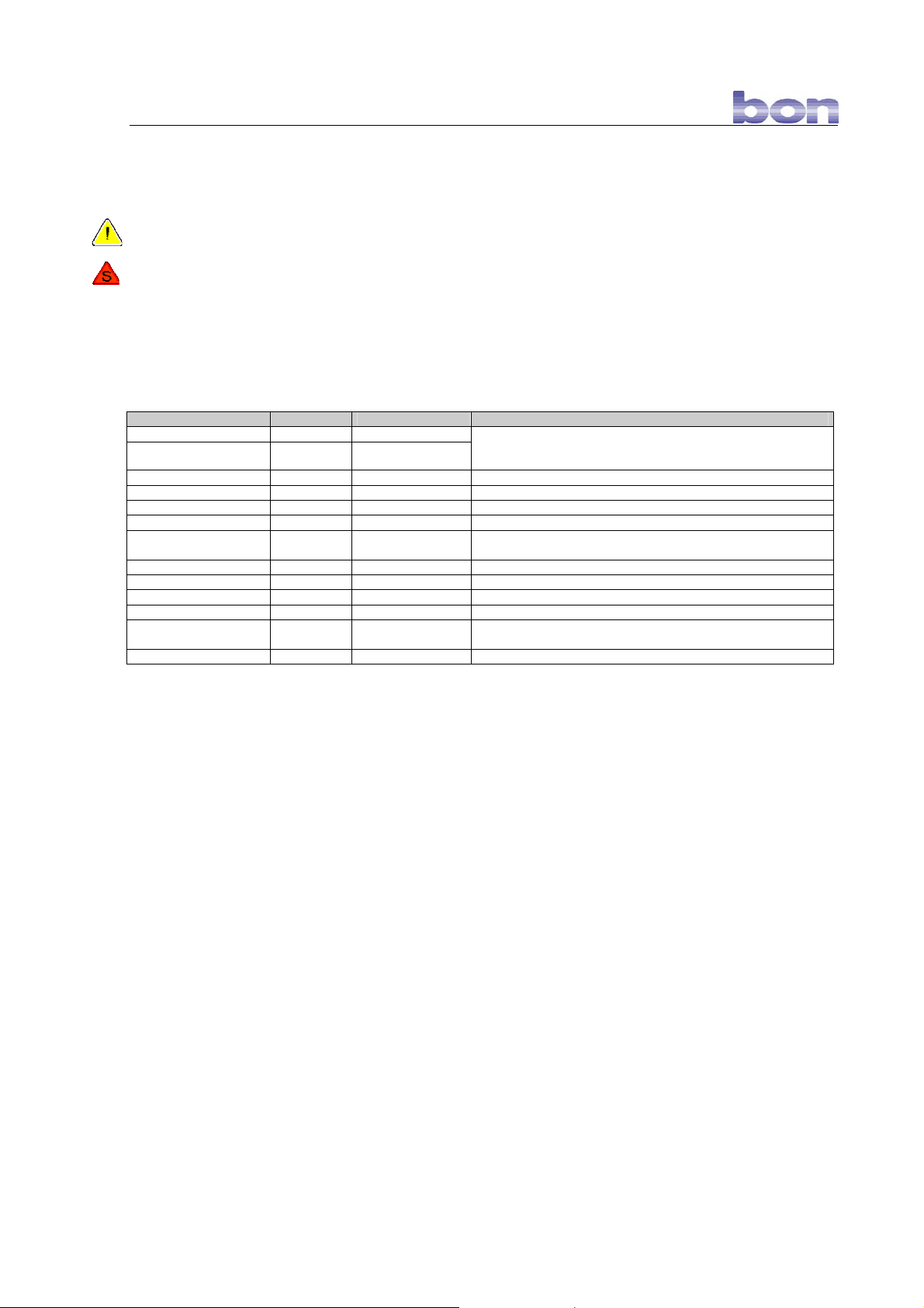
Only use fuses indicated in table 1 with the listed type (T) fuse values.
Before replacing a fuse, always pull out the mains plug or disconnect the refraction unit by
pressing the on/off-switch of the wall terminal box. Ensure that the refraction unit is cut off
from the electric supply. To reach fuses F3-F10 and F13, open the electric component casing
of the refraction unit underneath the work table by turning the knurled screws. When you
undo the screws, hold the casing fast with one hand. To reach the circuit boards, hinge down
the casing carefully.
Component Fuse Fuse value/A Location
Refraction uni F1 6.3
Refraction unit F2 6.3
Examination chair F3 3.15 Circuit board 2
Ambient light F4 5 Circuit board 2
Main transformer F5 5 Circuit board 2
Supply voltage F6 1 Circuit board 2
Table and hand-held
devices
Motors F8 3.15 Circuit board 2
Spotlight F9 3.15 Circuit board 2
Digital board F10 1.0 Circuit board 1
Wall terminal box F11 1.0 Wall terminal box if available
6 Vpower pack (wall
terminal box)
Dimmer F13 2 Protection casing for electric components in dimmer
F7 8 Circuit board 2
F12 0.5 Wall terminal box if available (option
Main fuses of refraction unit on mains (w/o wall terminal box)
Fuses are on wall terminal box in versions with wall terminal
box.
Table 1: Fuses of refraction unit
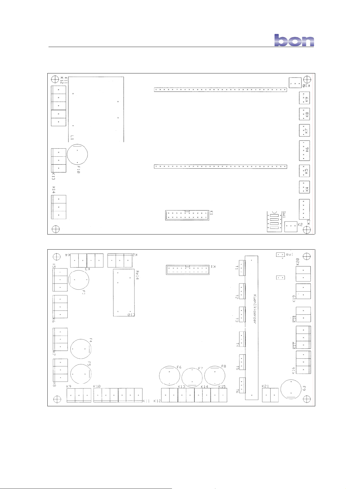
On the next page, the fuse locations on the circuit board are indicated.
18/27
Page 19
8 Maintenance and care bon E-30
Circuit board 1
Circuit board 2
19/27
Page 20

9 Guarantee bon E-30
9 Guarantee
Should defects as the result of material or production errors occur within 24 months of
purchase, we guarantee free-of-charge repair of the refraction unit or we will decide whether
to off you a free exchange, provided that:
A receipt with the date of purchase can be provided.
The device has been used properly and in accordance with the conditions of use.
Repairs have not been carried out by anyone other than the bon Optic customer
service team or persons authorised by bon Optic.
Guarantee services do not result in extension of the guarantee, nor do they represent the
start of the new guarantee. The sales guarantee is not applicable to consumables.
The terms and conditions of trade of bon Optic also apply.
20/27
Page 21
10 Circuit plans/technical data bon E-30
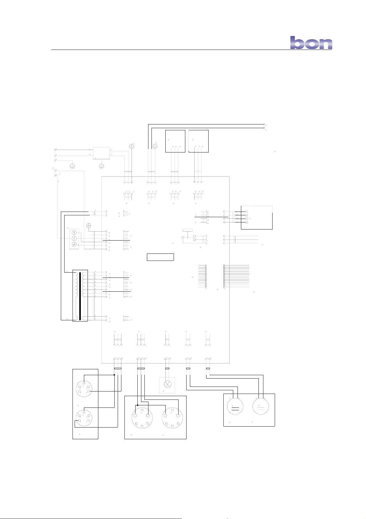
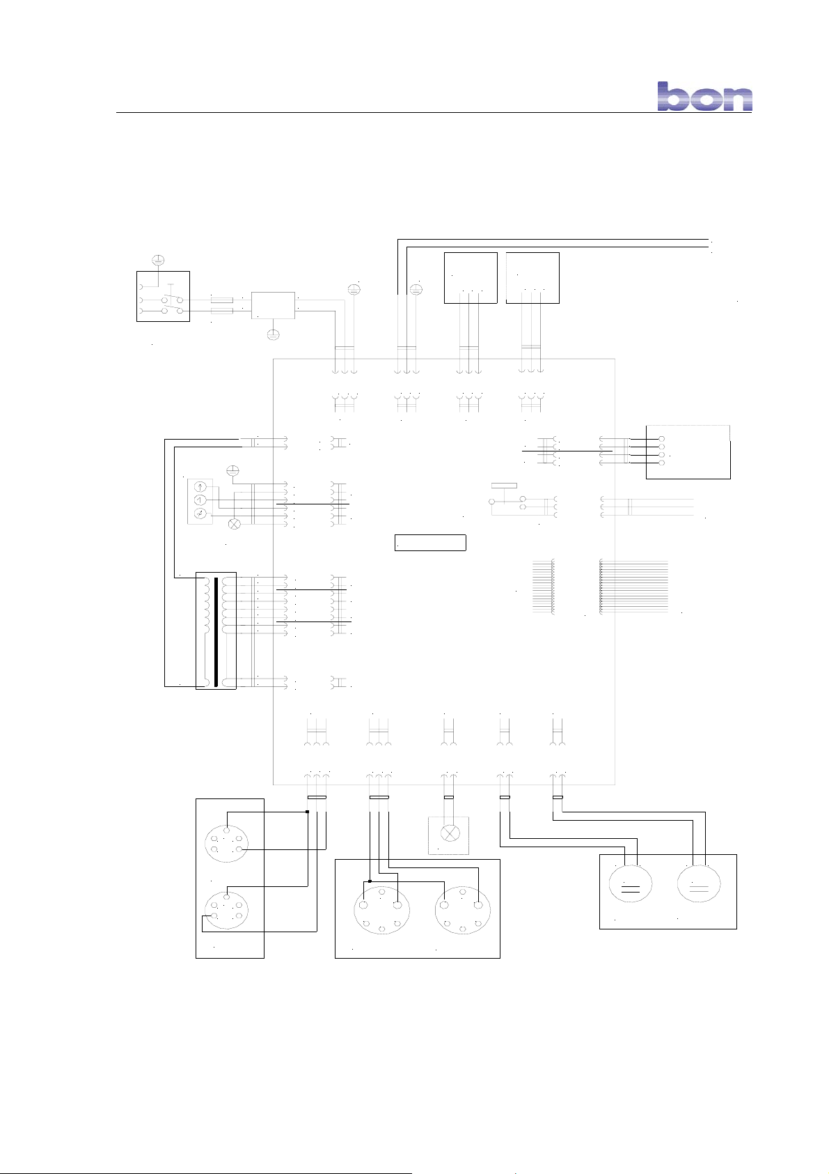
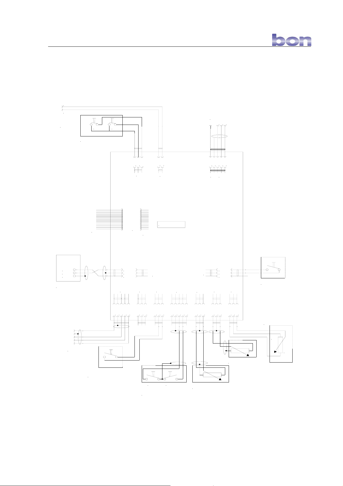
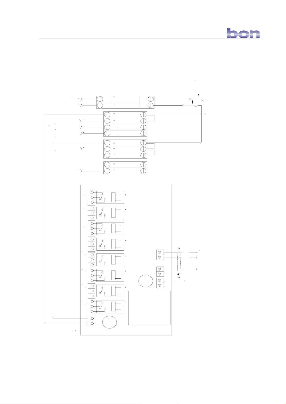
10 Circuit plans/technical data
Circuit plan of power board with wall terminal box
ChartProjector
LNPE
LNPE
TO WAK
2
1
PE
3
L-DIM.
4
L-TAST
N
L
MAINSUPPLY
FILTER
Aut.
Phoropter
LNPE
PE
LNPE
LNPE
PE
N
L
LNPE
L
N
TO DIGITAL-BOARD
K13
DIMMER
L
N
K8
br
bl
gr
gr
ws
rt
rt
sw
vi
vi
or
or
N
K9
L
PE
N
L-TAST
L
L-DIM.
L-DIM.
6 VAC
0 VAC
14 VAC
8 VAC
8 VAC
0 VAC
18 VAC
0 VAC
12 VAC
0 VAC
K10
K11
K12
K13
K14
K15
K21
K16 K17 K18 K19 K20
TG 1
TG 2
0 VAC
K7 K6 K5
REL4
POWER-BOARD
HG 1
HG 2
0 VAC
12 VAC
0 VAC
PE
K4
N
L-AUF
K3
L-AB
K2
K1
+/- 24V
+/- 24V
+/- 24V
+/- 24V
PE
1
EXAMINATION-
2
CHAIR
3
AUX 1
PCB-CONNECTOR
TO DIGITAL-BOARD
234
1
5
TABLEDEVICE 2
234
1
5
TABLEDEVICE 1
4
3
2
1
HANDHELDINSTRUMENT1
5
6
SPOT
4
3
5
6
2
1
HANDHELDINSTRUMENT2
gn rt rt gn
MM
TABLEENGINE
PHOROPTERENGINE
21/27
Page 22
10 Circuit plans/technical data bon E-30
Circuit plan of power board without wall terminal box
ChartProjector
LNPE
MAIN
POWER-ON
SWITCH
SI 1
SI 2
N
L
MAINSUPPLY
FILTER
Aut.
Phoropter
PE
N
L
PE
LNPE
L
N
TO DIGIT AL-BOARD
K13
DIMMER
L
N
ROOMLIGHT
LNPE
K8
br
bl
gr
gr
ws
rt
rt
sw
vi
vi
or
or
N
K9
L
PE
N
L-TAST
L
L-DIM.
L-DIM.
6 VAC
0 VAC
14 VAC
8 VAC
8 VAC
0 VAC
18 VAC
0 VAC
12 VAC
0 VAC
K10
K11
K12
K13
K14
K15
K21
K16 K17 K18 K19 K20
TG 1
TG 2
0 VAC
LNPE
K7 K6 K5
POWER-BOARD
HG 1
HG 2
0 VAC
LNPE
REL4
12 VAC
0 VAC
LNPE
PE
K4
N
L-AUF
K3
L-AB
K2
K1
PCB-CONNECTOR
+/- 24V
+/- 24V
+/- 24V
+/- 24V
PE
1
2
3
EXAMINATIONCHAIR
AUX 1
TO DIGITAL-BOARD
234
1
5
TABLEDEVICE 2
234
1
5
TABLEDEVICE 1
4
3
5
6
2
1
HANDHELDINSTRUMENT1
SPOT
4
3
5
6
2
1
HANDHELDINSTRUMENT2
gn rt rt gn
MM
TABLEENGINE
PHOROPTERENGINE
22/27
Page 23
10 Circuit plans/technical data bon E-30
Circuit plan of digital board
N
L
TO POWER-BOARD K7
CHAIR FOOT-SWITCH
UPDOWN
L
GND
K14
UP
DOWN
N
K13
I2C-BUS
TO WAK
GND
NA
K12 K11
SCL
gbgnbr
SDA
+5V
DIGITAL-BOARD
K1
K2
K5
GNDIN+5V
gb
HG 1 HG 2
ON/OFF HANDHELD
INSTRUMENTS
(switch closed = instrumen t on)
K6
GND
HG 1
+5V
GNDIN+5V
gn
ws
br
K10
K7
HG 2
NA
GNDIN+5V
ws
br
PHOROPTER-POSITION
POTENTIOMETER
IN
GND
+5V
K8 K9
GNDIN+5V
ws
br
rt
bl
GNDIN+5V
ws
br
TABLE-POSITION
POTENTIOMETER
CHAIR
SAFETY-STOP
(normal condition
closed)
POTENTIOMETER
FOR TABLE- AND
HANDHELD-DEVICES
min.
max.
br
ws
IR-OUT
GND
REMOTE-CONTROL
RECEIVER
gb
gn
ws
br
TO TABLE-KEYPAD
IR-IN+5V
GND
+5V
K3 K4
GND
+5V
IN
AGND
PCB-CONNECTION
A+5V
TO POWER-BOARD
ws
br
CHANGE-OVER SWITCH
TABLE-DEVICE 1 / 2
(switch closed = table-device1 on)
23/27
Page 24
10 Circuit plans/technical data bon E-30
Circuit plan of wall terminal box
Main-Switch
To Main-Supply Filter
Refraction Unit
Roomlight
Power-Board K11/3
Refraction Unit
Touch-I nput RoomlightRegulator
Refraction Unit
To Main-Supply Filter
Refraction Unit
Einspeisung
L N
1
3
4
2
PE
Aux 2 M addox Fix 2 Fix 1
F1 F2
L L N N N PE PE
L-gedimmt
L-getastet
I2C- Bus
to Digital-Board
rechts-schieben links-schieben rechts-dre he n links-drehen
Vorhang
Vorhang Vorhang Vorhang
F12
500mA
6 VAC
6 VAC
Rel 8Rel 7Rel 6Rel 5Rel 4Rel 3Rel 2Rel 1
F11
1A
Eingang
230VAC
gb
gn
br
6 VAC
max.
500mA
for Maddox etc.
Refraction Unit
24/27
Page 25
10 Circuit plans/technical data bon E-30
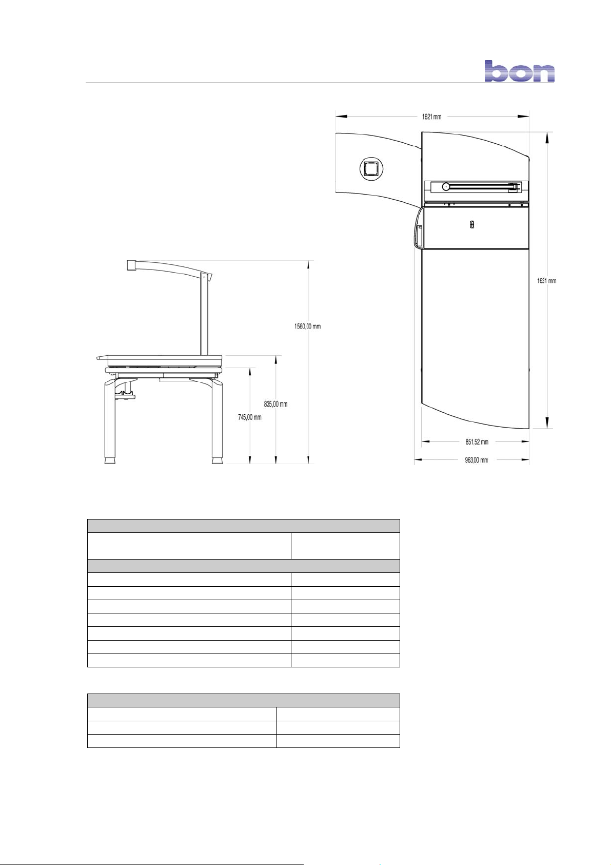
Weight
Maximum scope of equipment without
approx. 200 kg
devices
Electrical data of refraction unit
Mains voltage 230 V AC
Mains frequency 50 / 60 Hz
Connected load 750 VA
Workstation lamp 12 V AC / 20 W
Protection class I
Type of device B
Protection type IP 21
Operating conditions for refraction unit
Environmental temperature +10° C to + 40° C
Relative humidity from 30% to 75%
Air pressure 700 hPa to 1060 hPa
25/27
Page 26
10 Circuit plans/technical data bon E-30
Chair Elevation
Current supply 230 V / 50 Hz
Power intake 2,2 A
Protection class I
Max. axial strain 1800 N (ca. 170 kg)
ED (Switch in duration chair
S2 10% Basic 10 min.
column)
Elevation 215 mm
Speed under strain ca. 16 mm/s
Thermoswitch Yes
End switch up/down Yes
Disposal of old Electrical & Electronic Equipment (Applicable throughout the
European Union and other European countries with separate collection
programs)
This symbol, found on your product or on its packaging, indicates that this product should not
be treated as household waste when you wish to dispose of it. Instead, it should be handed
over to an applicable collection point for the recycling of electrical and electronic equipment.
If you have any further questions, please contact bon optic.
Should EMC disruptions (e
lectro-magnetic compatibility) occur, please contact bon Optic
customer support.
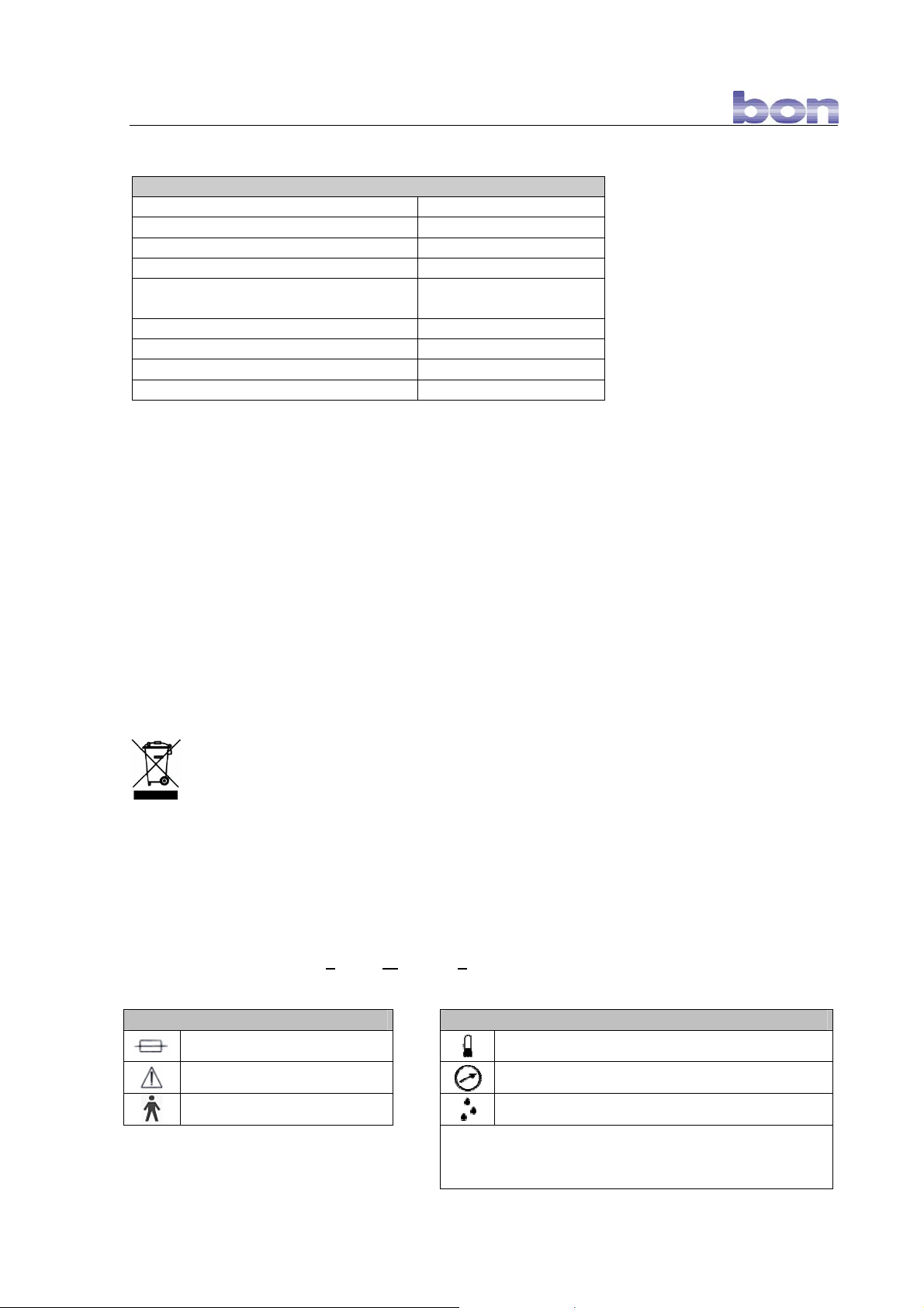
Label Symbols Transport requirements
Fuse
Read instruction manual
Application part type B
Temperature: -5 °C to +45 °C (+23 °F to +113 °F)
Air pressure: 650 hPa to 1100 hPa
Relative humidity: 25% to 80%
Maximum conditions – no longer than 60 days in a row
26/27
Page 27

Appendix bon E-30
Hersteller-Adresse:
(Manufacturer adress)
Gerätetyp / UMDNS-CODE:
(Device typ/ UMDNS-CODE)
Gerätebezeichnung:
(Device name)
Klassifizierung:
(Classification)
Wir erklären hiermit die Übereinstimmung des vorgenannten Produkts mit der
EU-Richtlinie 93/42/EWG über Medizinprodukte.
We declare the compliance of the device with the requirements of the Derective
93/42/EEC about medical devices.
EU - KONFORMITÄTSERKLÄRUNG
EC – DECLARATION OF CONFORMITY
bon
Optic Vertriebsgesellschaft mbH
Stellmacherstraße 14
D-23556 Lübeck
Untersuchungs-/Behandlungsplatz (18-014)
Refraktionseinheit bon E-30
Refraction unit bon E-30
1 (Richtlinie 93/42/EWG, Anhang IX, Regel 1)
1 (MDD 93/42/EEC, annex IX, rule 1)
Angewandete Normen:
(Applicable standards)
Das Gerät ist gekennzeichnet mit / The device is marked with
Lübeck, den 01. Juni 2004
(H. Jochen Kaber, Geschäftsführer)
DIN EN 60601-1 (03/96)
DIN EN 60601-1-2 (09/94)
EN 1441 (10/97)
27/27
 Loading...