

Page 1
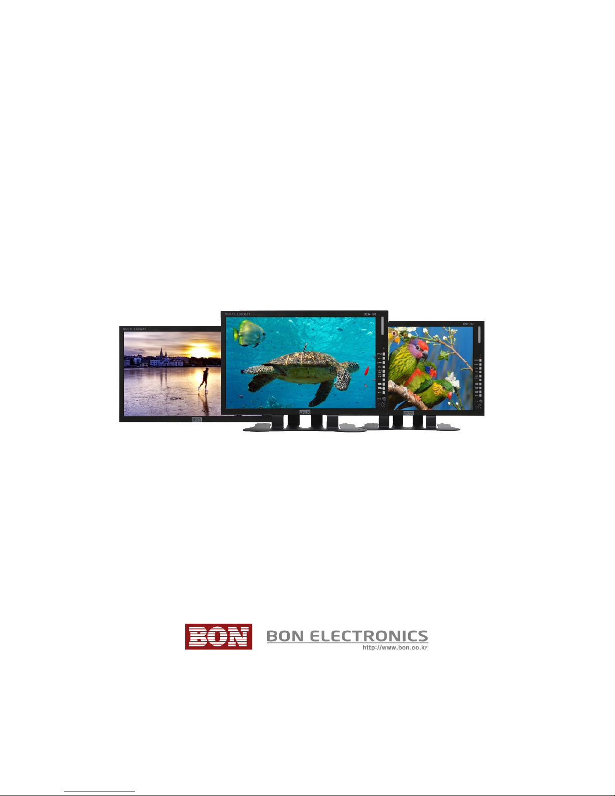
Multi-Format Broadcast
Monitor
BEM-182, 212, 242
User’s Guide
Page 2

Contents
Introduction.................................................................................................................................3
Features.......................................................................................................................................3
Safety Instructions.......................................................................................................................4
Front............................................................................................................................................5
Tally.............................................................................................................................................7
Rear.............................................................................................................................................7
OSD Menu.......................................................................................................................................9
VIDEO........................................................................................................................................9
DISPLAY 1...............................................................................................................................11
DISPLAY 2...............................................................................................................................13
COLOR.....................................................................................................................................15
MARKER..................................................................................................................................16
OSD 1........................................................................................................................................17
OSD 2........................................................................................................................................19
AUDIO......................................................................................................................................20
GPI............................................................................................................................................22
SYSTEM...................................................................................................................................23
Monitor Control via Serial Port................................................................................................24
USB Firmware Update..............................................................................................................24
External Remote Control..........................................................................................................25
List of Compatible Video Formats (HDMI)..............................................................................26
List of Compatible Video Formats (SDI)..................................................................................27
Specifications............................................................................................................................29
Dimensions................................................................................................................................35
Troubleshooting........................................................................................................................36
Warranty Information................................................................................................................38
Modification of Product............................................................................................................38
Caution on Menu Operation......................................................................................................38
Caution for Monitor Placement.................................................................................................38
Caution for Usage.....................................................................................................................38
2
Page 3

Features
Firmware Update with USB Memory
Focus Assistance/False Color (SDI)
Waveform/Vectorscope (SDI)
Closed Caption (CEA-608/708) (SDI)
Time Code (SDI)
8~16ch Audio Level Meter
Video Exposure Range Check (SDI)
UMD Mode (SDI)
AFD & V-CHIP (SDI)
Various Markers
H/V Delay (SDI)
Tally LED Control Output R/G/B/W Internal Patterns Rack & VESA Mount (Option)
3G SDI input (Level A/B)
1~16Ch Audio Level Meters
3
Page 4

Safety Instructions
• To help avoid damaging your monitor, connect only one power (AC or DC) in operation.
• Rough handling of product may cause physical damage or malfunction.
• Never insert anything metallic into the monitor openings. Doing so may create the danger of
electric shock.
• To avoid electric shock, never touch the inside of the monitor. Only a qualified should open the
monitor’s case.
• Openings in the monitor cabinet are provided for ventilation. To prevent overheating, these
openings should not be blocked or covered.
• Put your monitor in a location with low humidity and a minimum of dust. Avoid places like
damp basement or dusty hallways.
• Place the monitor on a solid surface and treat it carefully. The screen is made of glass and can be
damaged if dropped or sharply hit.
• Do not attempt to remove the back cover, as you will be exposed to a shock hazard. The back
cover should only be removed by qualified service personnel.
• Unplug the monitor power before you connect external devices to the monitor.
• If your monitor does not operate normally, or if there are any unusual sounds or smells coning
from it, unplug it immediately and contact us.
• Please do not disassemble the monitor. No service will be provided in that case.
• Displaying fixed picture for a long time may cause an afterimage or dead spots. To recover LCD
pixels, display whole white picture on screen for a n hour or two and pixels will be recovered.
• No service will be provided for user’s own color calibration.
4
Page 5
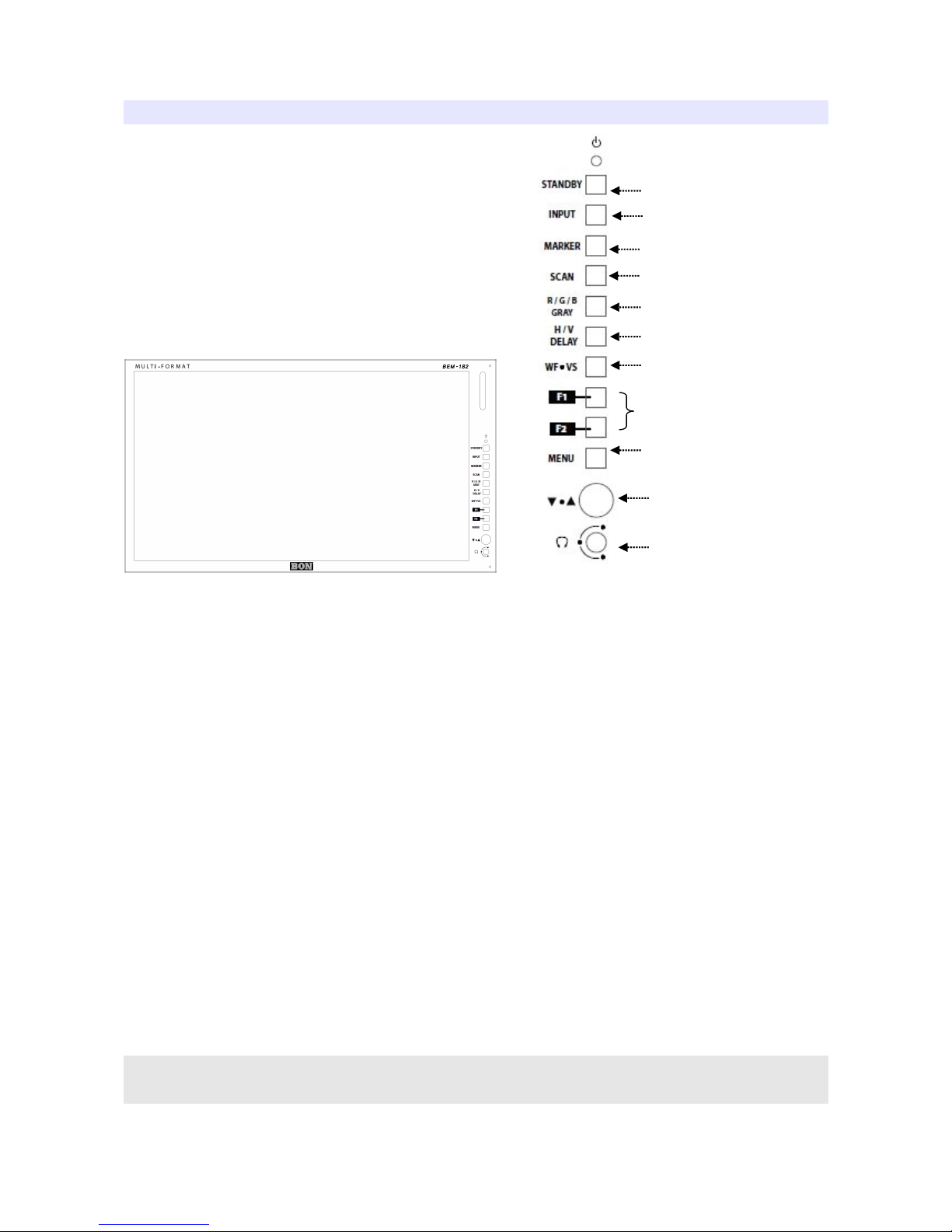
Front
①
②
③
④
⑤
⑥
⑦
⑧
⑨
⑩
⑪
1) Power (Standby) Button
2) Input
HDMI / SDI Input Selection.
3) Marker On/Off
4) Scan
Switches scan mode.
5) R/G/B/Gray
Switches to display Red, Green, Blue or Gray color only.
6) H/V Delay
Displays ancillary data.
7) WF/VS (SDI)
Displays waveform, vectorscope.
* Some afterimage might be left on Waveform when the input picture
freezed long on interlace signal.
5
Page 6

* On SDI 2K input with Psf scanning mode, displaying Circle or
Horizontal Line pattern might cause an afterimage effect. However, it
will be disappeared after the picture is changed.
8) Function Keys
User-preferred function can be assigned to function keys. Assignable functions are listed below.
● ALM (Audio Level Meter) Display On/Off
● Freeze Frame On/Off
● UMD Display
● Front Button LED On/Off
● Video Loss Display On/Off
● Focus Assist
● False Color
● Exposure Range Check
● Audio Mute
● 1:1 Scan On/Off
● Caption Display
● Time Code
9) Menu
Displays Menu.
10) Adjust Knob
Works as arrow keys or selector.
11) Phone Jack
Headphone Output.
6
Page 7
Tally
Tally mode displays Red, Green, Amber color by the input from tally (RJ-45 GPI) input port.
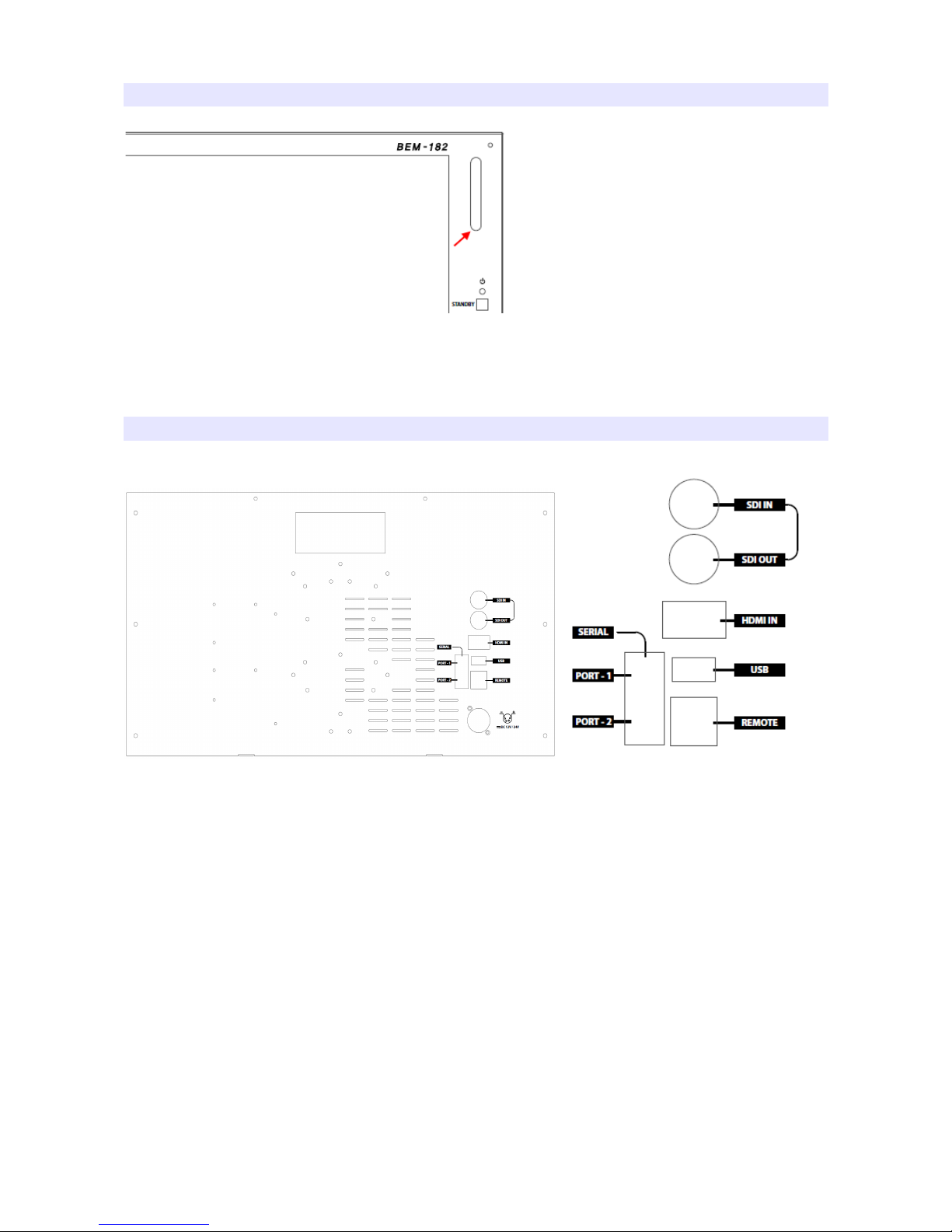
Rear
1) SDI IN
2) SDI OUT
SDI Loop-through out.
3) HDMI IN
4) USB
USB Port for firmware update.
5) SERIAL 1
Serial port for firmware update and monitor control.
7
Page 8

6) SERIAL 2
Serial port for firmware update and monitor control.
7) REMOTE
Ethernet port for monitor control.
8
Page 9
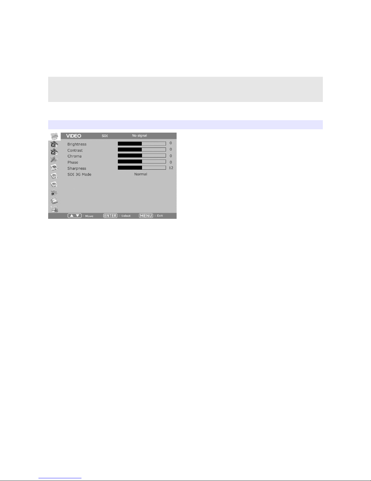
OSD Menu
Menu opens up by pressing Menu button. This button also works as Exit button on the Menu. The
brightness knob works as up/down arrow. To select something, press either enter button or the knob.
* The menu may disappear on no signal or unstable signal input.
* Menu setting is saved for each input mode. So the user should make
selection on an appropriate input mode.
VIDEO
Brightness
Adjust brightness.
Contrast
Adjust contrast.
Chroma (Hue)
Adjust chroma.
Phase
Adjust phase.
Sharpness
Adjust sharpness. Default: 12s.
SDI 3G Mode
Set this mode if the input is 3G HD SDI. SDI 3G mode support SMPTE standards listed below:
▶ A_MS1_YCbCr422_10
: 3G SDI Level-A Mapping Structure 1 – YCbCr 4:2:2/10 bit
▶ A_MS2_YCbCr444_10
9
Page 10

: 3G SDI Level-A Mapping Structure 2 – YCbCr 4:4:4/10 bit
▶ A_MS2_RGB444_10
: 3G SDI Level-A Mapping Structure 2 – RGB 4:4:4/10 bit
▶ A_MS3_YCbCr444_12
: 3G SDI Level-A Mapping Structure 3 – YCbCr 4:4:4/12 bit
▶ A_MS3_RGB444_12
: 3G SDI Level-A Mapping Structure 3 – RGB 4:4:4/12 bit
▶ A_MS4_YCbCr422_12
: 3G SDI Level-A Mapping Structure 4 – YCbCr 4:2:2/12 bit
▶ B_MS1_YCbCr422_10
: 3G SDI Level-B Mapping Structure 1 – YCbCr 4:2:2/10 bit
▶ B_MS2_YCbCr444_10
: 3G SDI Level-B Mapping Structure 2 – YCbCr 4:4:4/10 bit
▶ B_MS2_RGB444_10
: 3G SDI Level-B Mapping Structure 2 – RGB 4:4:4/10 bit
▶ B_MS3_YCbCr444_12
: 3G SDI Level-B Mapping Structure 3 – YCbCr 4:4:4/12 bit
▶ B_MS3_RGB444_12
: 3G SDI Level-B Mapping Structure 3 – RGB 4:4:4/12 bit
▶ B_MS4_YCbCr422_12
: 3G SDI Level-B Mapping Structure 4 – YCbCr 4:2:2/12 bit
▶ B_2X_DS1_YCbCr422_10
: 3G SDI Level-B Data Stream 1 – YCbCr 4:2:2/10 bit, Dual Link SMPTE-372M
▶ B_2X_DS2_YCbCr422_10
: 3G SDI Level-B Data Stream 2 – YCbCr 4:2:2/10 bit, Dual Link SMPTE-372M
Especially for 3G Level B signals, the format should be set manually.
Also, be aware that the format information might be lost on power down.
10
Page 11
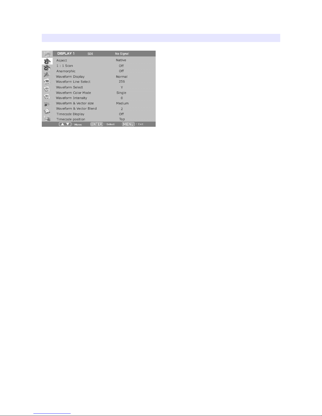
DISPLAY 1
Aspect
Set the aspect ratio of the screen. 16:9, 4:3, Native(Original) are selectable.
1:1 Scan
Set this on to display picture in 1:1 pixel mapping.
Anarmorphic
Set this mode to resize the screen to 3.56:1, 2.74:1, 2.59:1, 2.55:1, 2.40:1, 2.39:1, 2.35:1, 1.85:1,
1.75:1, 1.66:1, or 1.37:1.
Waveform Display
Select waveform display mode. Choose Normal to analyze whole screen, choose Line Select to
analyze a specific line of the screen.
Waveform Line Select
Select the line when you select Line Select mode for Waveform display.
Waveform Color Mode
Choose either Single or Mixed.
Waveform Intensity
Set waveform color’s intensity between 0~63.
WFM & Vector Size
Set Waveform and Vectorscope size among three kinds.
WFM & Vector Blend
Set transparency of Waveform and Vectorscope window between 0~6.
11
Page 12

Timecode Display
Set this mode on to display timecode from SDI signal. Select the appropriate timecode that you
wish to display among LTC (Longitudinal Time Code), VITC (Vertical Interval Time Code),
DVITC (Digital Vertical Interval Time Code).
Timecode Position
Set Top or Bottom position for timecode.
12
Page 13
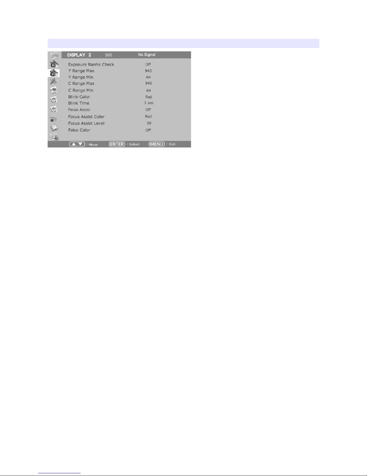
DISPLAY 2
Exposure Range Check (Video Range Check)
Checks Y, C level and displays over-exposed or under-exposed area on screen. The base value can
be Y, Cb, or Cr.
Y Range Max / Min
Set Y range value for range check.
C Range Max / Min
Set C range value for range check.
Blink Color
The filled area color by range check can be either Black, Blue, Green or Red.
Blink Time
Set blinking time of the area between 1 to 5 seconds.
Focus Assist
Turns on Focus Assist mode. This mode can be set also by pressing Focus Assist button in front.
Focus Assist Level (Sensitivity)
The sensitivity of the focus assist function can be set between 0 to 48.
Focus Assist Color
Set brush color of focus assist mode among Blue, Green, and Red.
False Color
Shows pictures in specific colors as its luminance level other than the original colors. Much
exposed area is filled with red while little exposed area is purple.
13
Page 14

* 10-bit, 12-bit Dithered gradient pattern might not be displayed
clearly in this mode.
14
Page 15
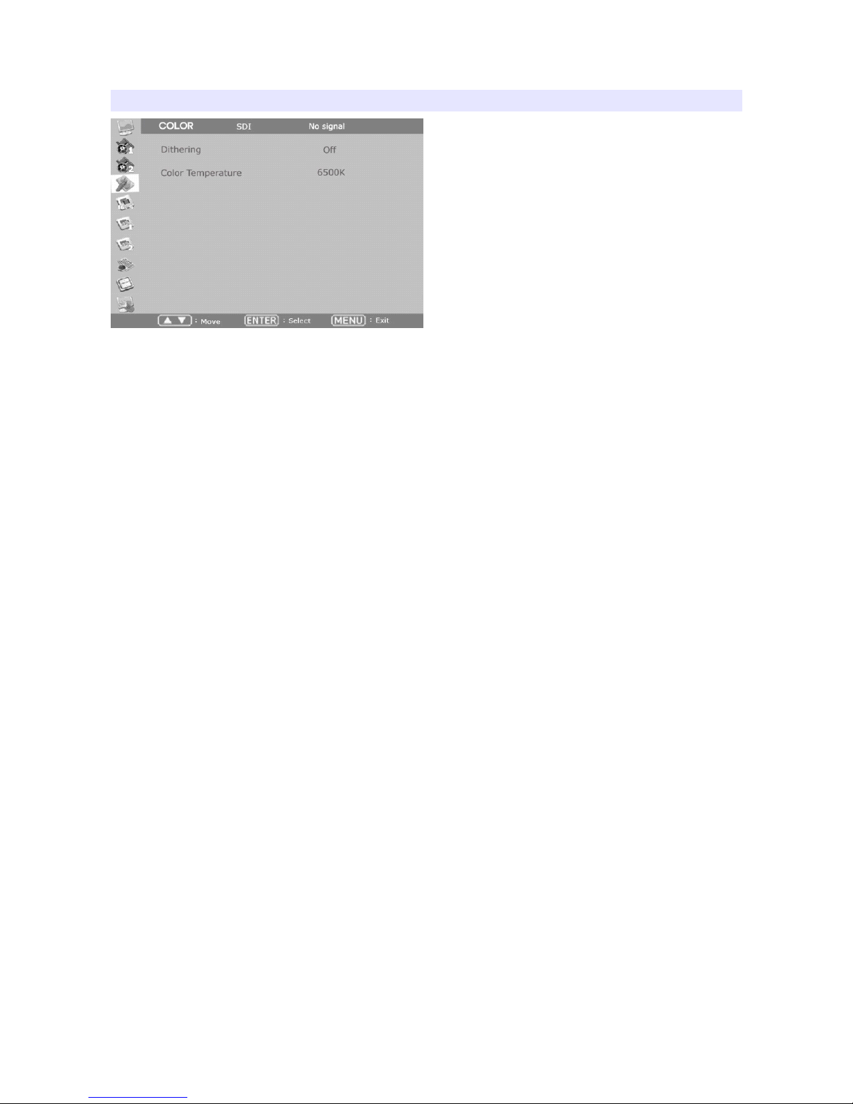
COLOR
Dithering
Set this mode on to display gradient more smoothly.
Color Temperature
VAR, 3200K, 5400K, 6500K, 9300K color temperatures are preset and selectable by user. On User
mode, user can adjust RGB gain and bias. Adjusting on User mode is recommended to professional
users.
15
Page 16
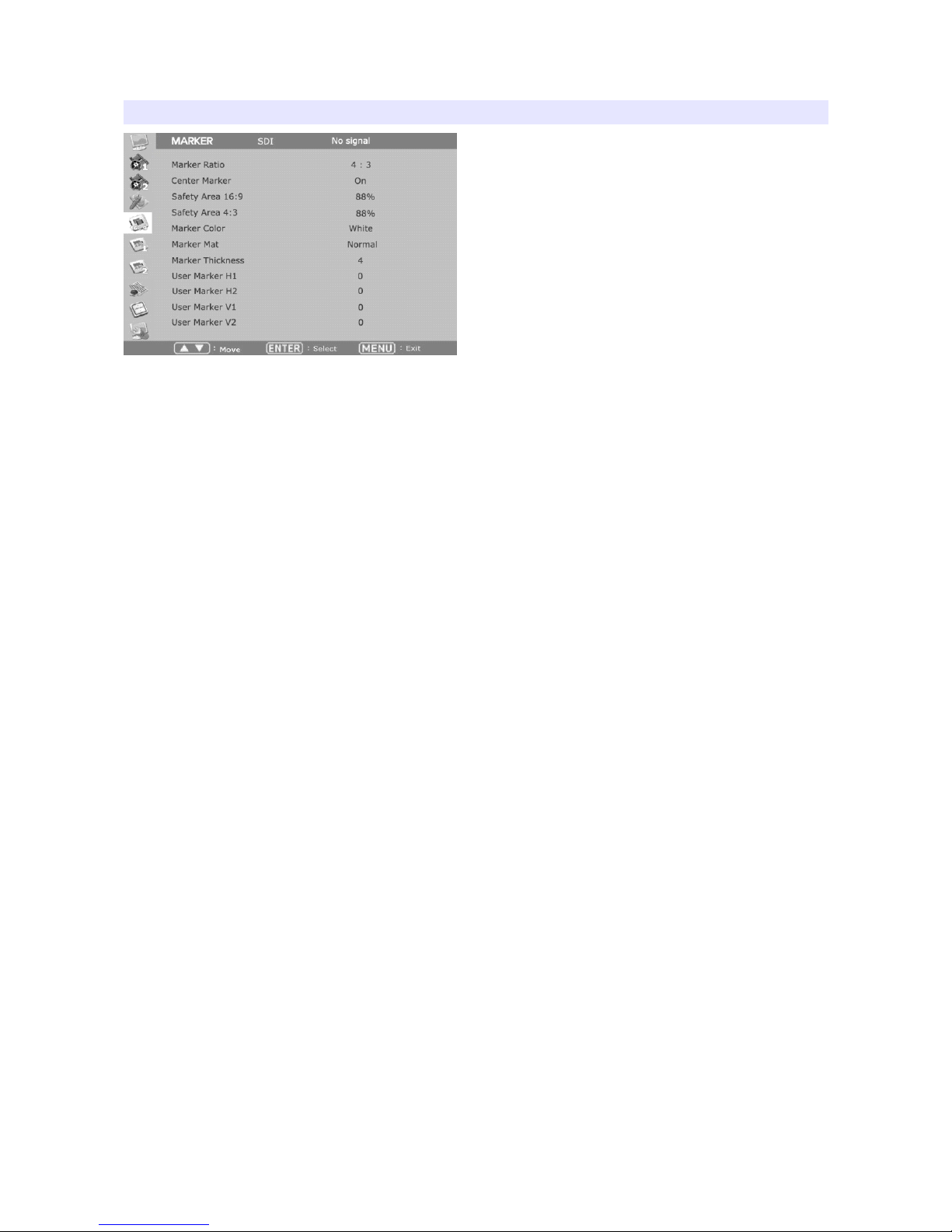
MARKER
Marker Ratio
Select one of preset markers or user marker. To display marker, press Marker button in front of the
monitor.
Center Marker
Set preference to display center marker or not.
Safety Area 16:9
Adjust size of the safety area when marker displayed on 16:9 screen.
Safety Area 4:3
Adjust size of the safety area when marker displayed on 4:3 screen.
Marker Color
Select marker’s color among White, Red, Green, Blue, Gray and Black.
Marker Mat
Set how to display outside of the safety area. Normal, Half(Gray), Black are selectable.
Marker Thickness
Set marker thickness between 1 to 10.
User Marker H1 / User Marker H2 / User Marker V1 / User Marker V2
Set user marker’s position. H1 for left, H2 for right, V1 for top, V2 for bottom. The positions are
saved as the selected marker name such as USER1.
16
Page 17
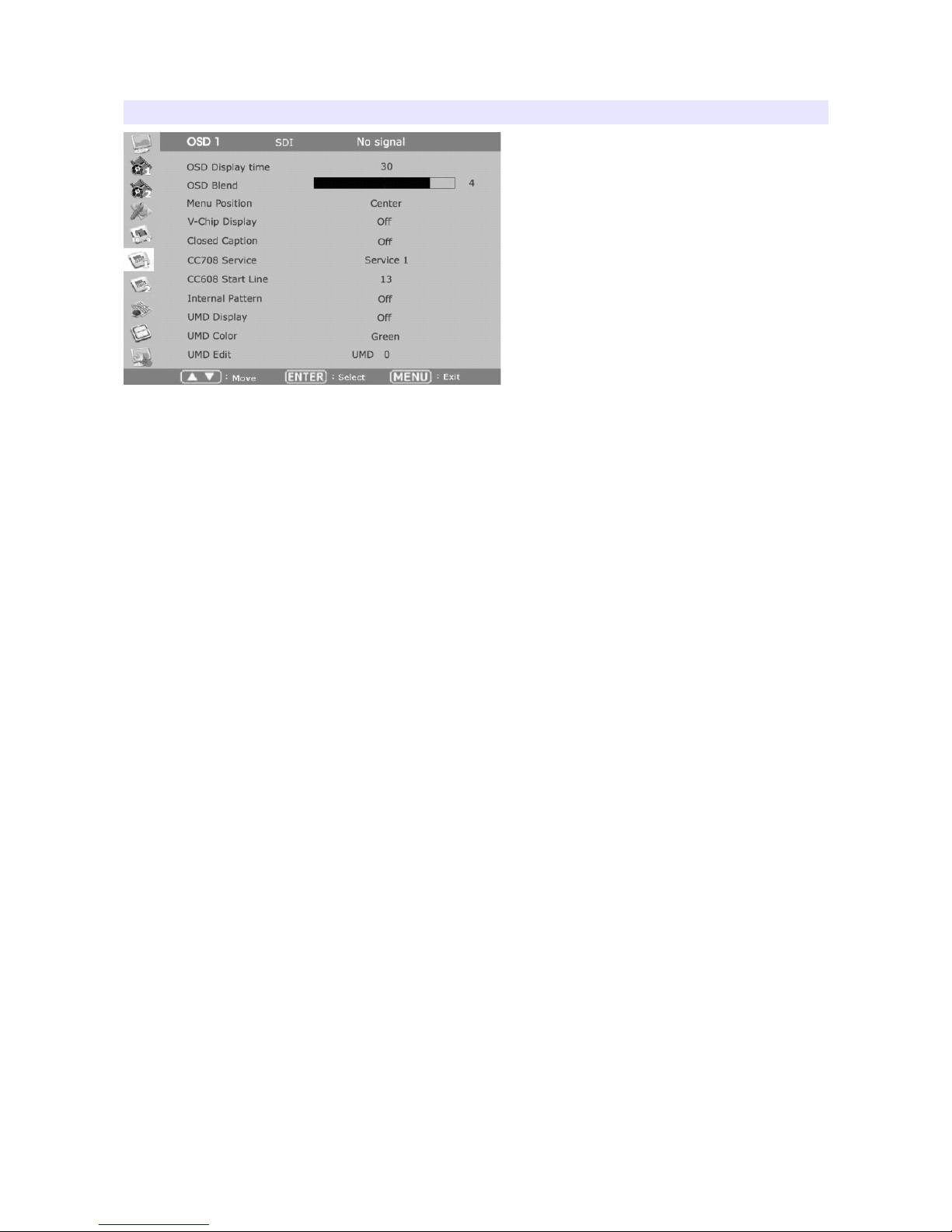
OSD 1
OSD Display Time
Set OSD menu display time. Choose 0 for infinite.
OSD Blend
Set transparency of the menu between 0 to 5.
OSD(Menu) Position
Set menu position among Left Top, Right Top, Left Bottom, Right Bottom and Center.
V-Chip
SD-SDI, Composite signal might contain V-Chip data. Turn this mode on to display V-Chip
information on screen.
Closed Caption
Select one of 608 Line 21, 608 VANC, 608 Transcoded, 708 to display Closed Captions. In special
condition such as menu display status, captions are not displayed.
CC708 Service
Select one of CC service as your preference.
Service 1: general captions.
Service 2: translated captions.
Service 3,4: not assigned.
CC608 StartLine
Display line of captions are selectable by user. (e.g. 13)
17
Page 18

Internal Pattern
To test monitor display without signal, turn this mode on. Several patterns such as Color Bars, Blue,
Green, Red, White and Black are selectable.
UMD Display
Set this mode on to display UMD text on screen.
UMD Color
Select UMD text color among Red, Green, and Amber.
UMD Edit
Set the UMD source ID to display on screen.
18
Page 19
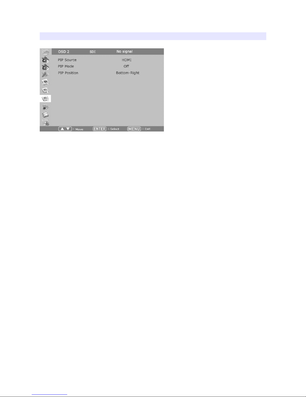
OSD 2
PIP Source
Selects the main picture source for Picture-in-Picture mode. The sub-picture source is automatically
selected to the other input. (e.g. If HDMI is set as main, SDI is automatically set as sub-picture)
PIP Mode
Adjusts mode of the sub-picture among Small, Large, or Side by Side.
PIP Position
Selects position of the sub-picture.
19
Page 20
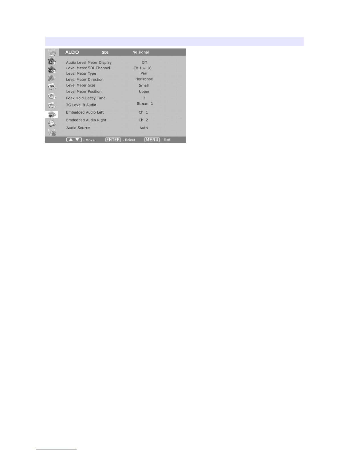
AUDIO
Audio Level Meter
Turns on/off audio level meters.
Level Meter SDI Channel
Set the audio channels to display.
Level Meter Type
Select one of two types: pair or group.
Level Meter Direction
Select one of two orientations : Horizontal or Vertical.
Level Meter Size
Select the size of the meters : Small or Large.
Level Meter Position
Select the position of the meters : Upper or Lower.
Peak Hold Decay Time
Set the decay time of the meters.
3G Level B Audio
Select one audio signals when there are two inputs.
Embedded Audio Left
Select audio channel for left (Ch 1 ~ 15)
20
Page 21

Embedded Audio Right
Select audio channel for right (Ch 2 ~ 16)
Audio Source
Select audio source for speaker among Auto / SDI / HDMI.
When both SDI, HDMI cables are connected, It is able to listen to SDI
audio on HDMI video input by this menu. However, It is not able to
listen to HDMI audio on SDI video input.
21
Page 22
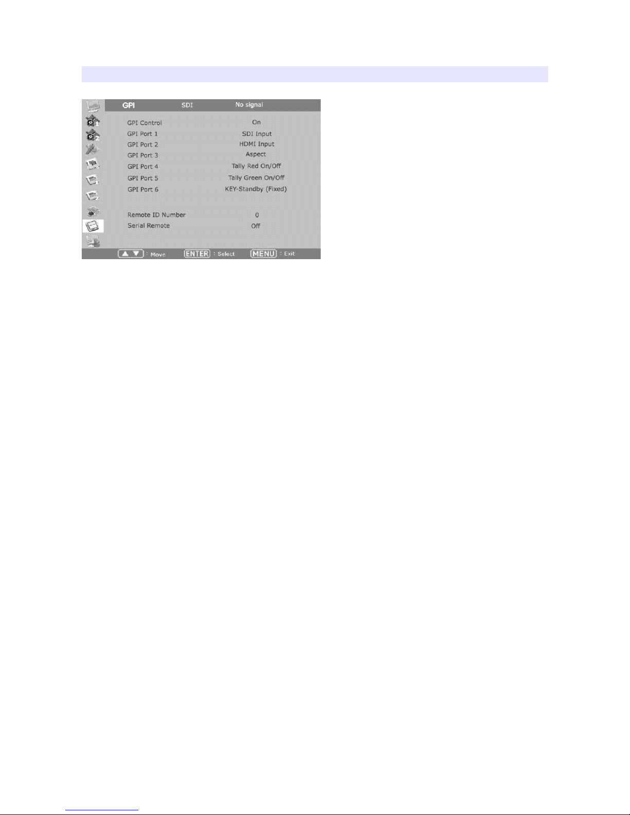
GPI
GPI Control
Turns on/off external monitor control function.
GPI Port 1,2,3,4,5,6
Assigns each GPI port’s function. (e.g. SDI 1 input, HDMI input, Tally Red) See EXTERNAL
REMOTE CONTROLLING section for details.
Remote ID Number
Assigns the ID for the monitor to control through serial port. 0 to 99 can be assigned.
Serial Remote
Turns serial remote function on. All front buttons are locked on this mode. To exit from this mode,
press and hold Menu button for 3 seconds.
22
Page 23
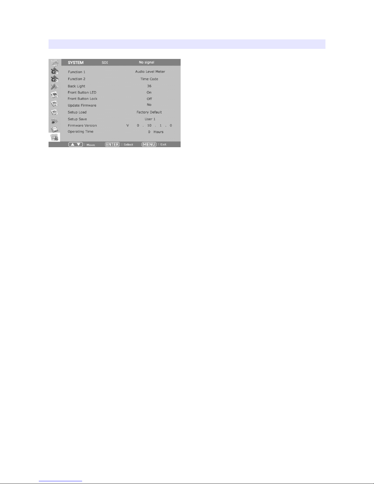
SYSTEM
Function 1,2
Assigns a function to each function button.
Backlight
Set the backlight intensity from 0 to 40. An LCD panel requires more than 30 minutes to be settled
to a new backlight value.
Front Button LED
Set front LEDs on/off status.
Font Button Lock
Locks front buttons not to work. Press and hold Menu button for 3 seconds to exit from this mode.
Update Firmware
Turns update mode on. Select Serial or USB port for update. After firmware update, the monitor
should be turned off/turned on, and Factory Default should be loaded before use.
Setup Load
Load monitor settings from Factory Default, User 1/2/3/4.
Setup Save
Save current monitor setting to use later. 4 settings can be saved.
Firmware Version
This version number is required when you request for service.
Operating Time
This indicates total hours that the monitor operated.
23
Page 24
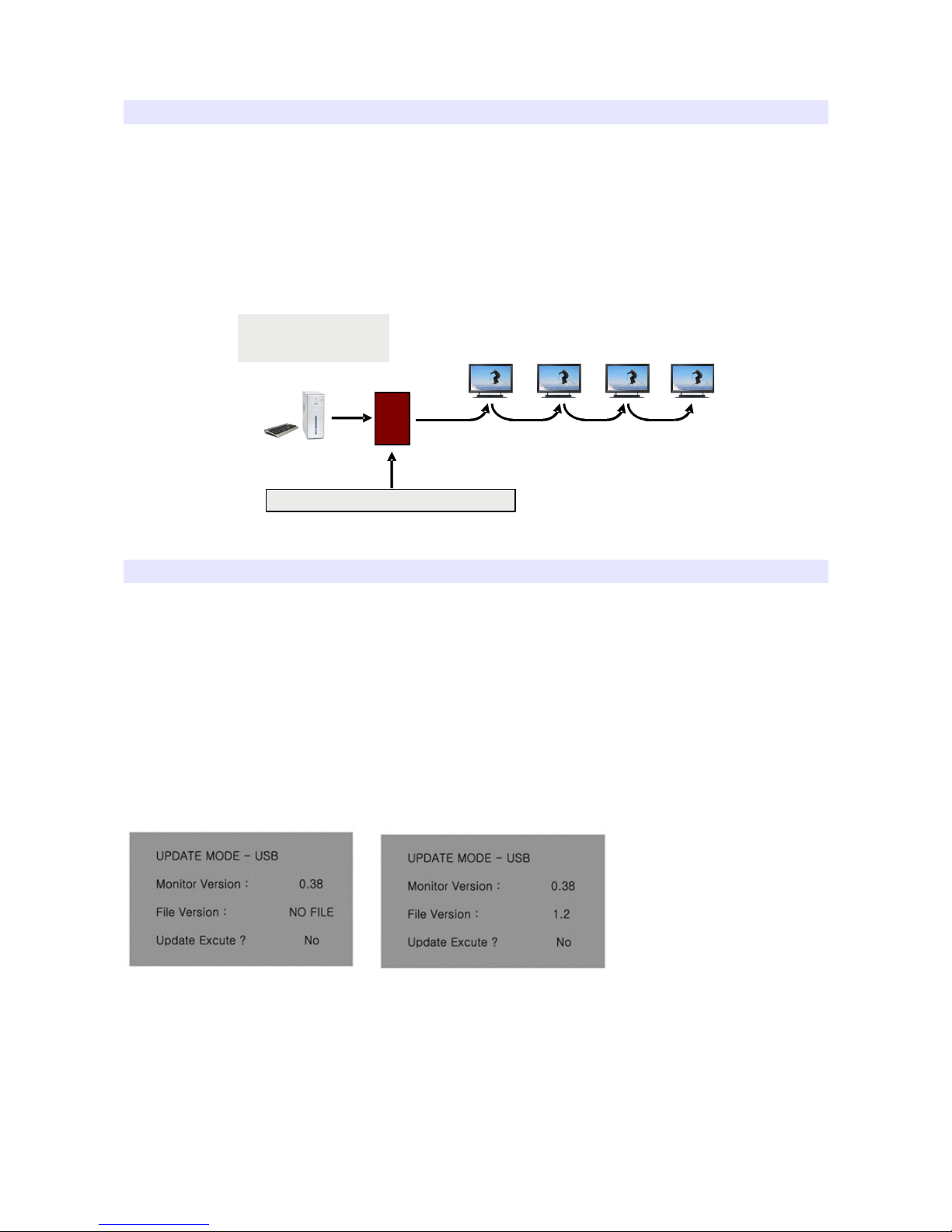
Monitor Control via Serial Port
This is optional feature of the monitor.
User can control multiple monitors via serial port on the back. Connect PC and monitor with RS422 (general telephone cable), using an appropriate gender. (e.g. a RS-232C to RS-422 gender, or a
USB to RS-232C to RS-422 gender)
In most cases this kind of gender is needed because PC does not have phone port, but RS-232C port
or USB.
PC Software BWS-100 will be provided as request.
USB Firmware Update
To update your monitor's firmware, request for a new firmware file to your local reseller or to BON
Electronics.
Move the file on a USB flash memory, insert it to your monitor. Please beware the file should be
located in the root(top folder level).
Also, the USB flash memory should have FAT32 or FAT file system. (USB memory has FAT32
file system, usually)
Set Update Firmware item as USB from SYSTEM menu.
Some part of firmware cannot be updated by USB updating procedure, so please get help
from your local dealer or expert before you update firmware with USB memory.
Error Message when USB access
or file not exist
Message when file on USB
detected
You can also use Serial Port and your PC to update the firmware. Please request for help to your
local dealer or directly to BON Electronics.
24
Adaptor (RS-232C to RS-422 Converter)
PC
(Wall System Controller)
BWS-100
Page 25
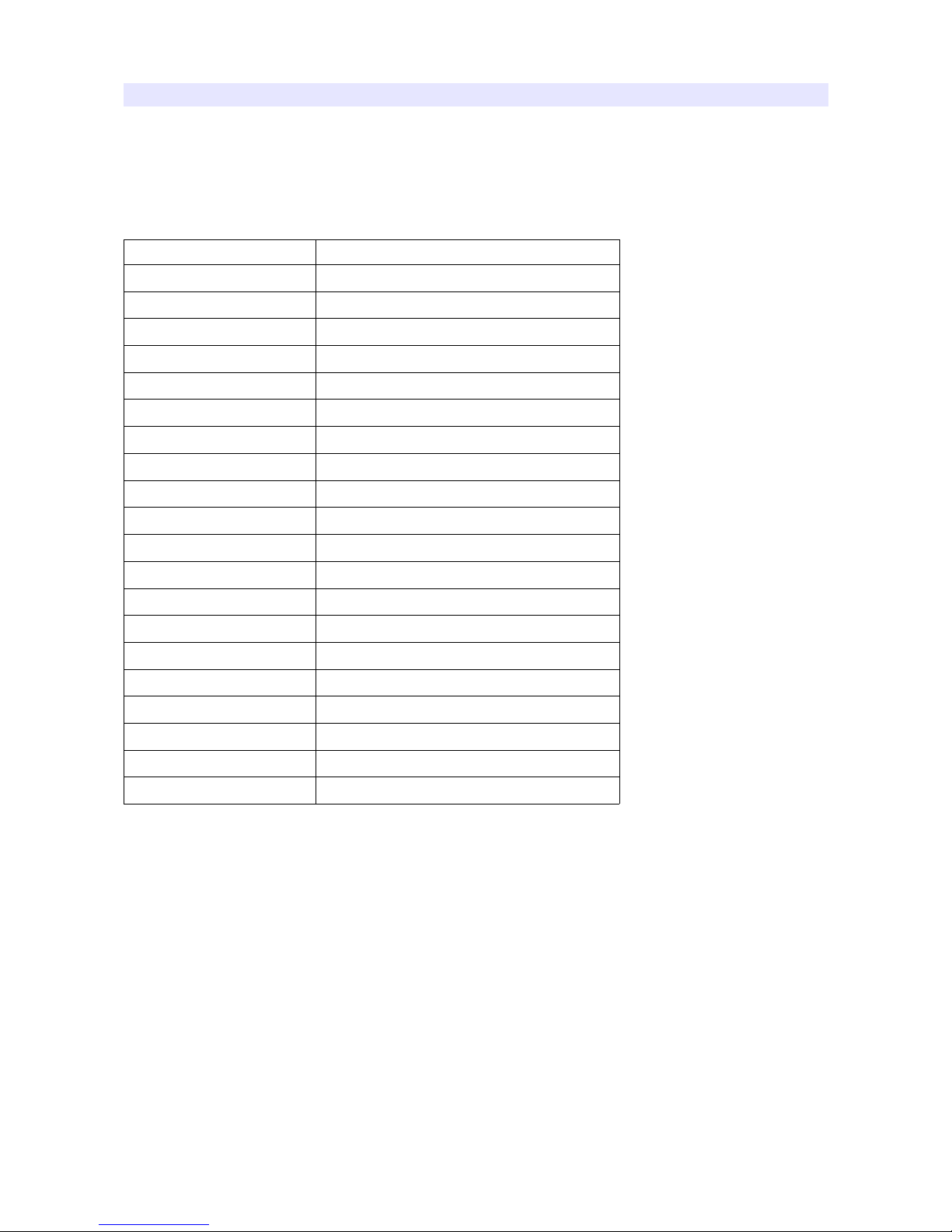
External Remote Control
Connecting GPI Port(RJ-45)
Turning the monitor off is recommended before cable connection. Assignable functions are listed
below.
Function Name Description
SDI-1 Input
Switches the input to SDI-1
SDI-2 Input
Switches the input to SDI-2
HDMI Input
Switches the input to HDMI
YPbPr Input
Switches the input to YPbPr
CVBS-1 Input
Switches the input to CVBS-1
CVBS-2 Input
Switches the input to CVBS-2
CVBS-3 Input
Switches the input to CVBS-3
KEY-UP ▲
CURSOR UP on Menu Control.
KEY-DOWN ▼
CURSOR DOWN on Menu Control.
KEY- MENU
Menu On/Off
KEY-ENTER
Enter Button
Aspect
Aspect On/Off
1:1 Scan On/Off
1:1 SCAN Function On/Off
H/V Delay On/Off
H/V Delay Function On/Off
TC Display On/Off
TC Display On/Off
ALM Display On/Off
Audio Level Meters Display On/Off
Freeze On/Off
Freeze Frame On/Off
Front Button LED On/Off
Front Button LED On/Off.
Tally Red On/Off
Tally Red LED On/Off
Tally Green On/Off
Tally Green LED On/Off
Backlight
Set the backlight intensity from 0 to 40. An LCD panel requires more than 30 minutes to be settled
to a new backlight value.
Front Button LED
Set front LEDs on/off status.
25
Page 26
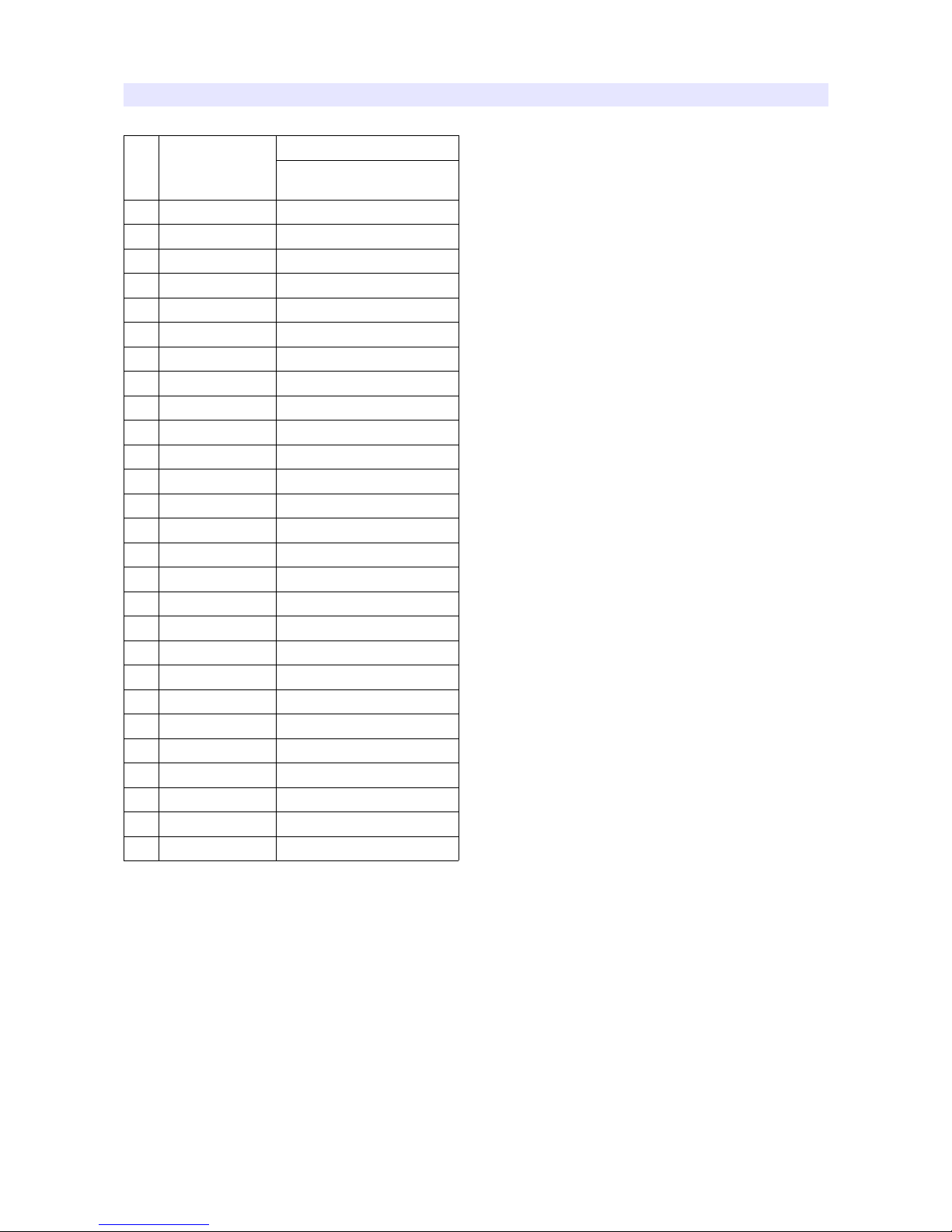
List of Compatible Video Formats (HDMI)
NO
Signal Input
Formats
INPUT
HDMI
1 NTSC O
2 PAL O
3 720*576/50i O
4 720*480/59.94i O
5 720*480/60i O
6 720*576/50p O
7 720*480/59.94p O
6 720*480/60p O
8 1280*720/23.98p O
9 1280*720/24p O
10 1280*720/25p O
11 1280*720/29.97p O
12 1280*720/30p O
13 1280*720/50p O
14 1280*720/59.94p O
15 1280*720/60p O
16 1920*1080/50i O
17 1920*1080/59.94i O
18 1920*1080/60i O
19 1920*1080/23.98p O
20 1920*1080/24p O
21 1920*1080/25p O
22 1920*1080/29.97p O
23 1920*1080/30p O
24 1920*1080/50p O
25 1920*1080/59.94p O
26 1920*1080/60p O
26
Page 27
List of Compatible Video Formats (SDI)
NO
Input Signal
Formats
HD/SD-SDI
Single
3G
YUV4:2:2
3G
YUV4:4:4
3G
RGB444
1 NTSC
√
- - -
2 PAL
√
- - -
3 525/60i (SD)
√
- - -
4 625/50i (SD)
√
- - -
5 720*480/59.94p - - - -
6 720*576/50p - - - -
7 1280*720/23.98p - - - -
9 1280*720/24p - - - -
9 1280*720/50p
√
-
√ √
10 1280*720/59.94p
√
-
√ √
11 1280*720/60p
√
-
√ √
12 1920*1035/59.94i
√
-
√ √
13 1920*1035/60i
√
-
√ √
14 1920*1080/50i
√
-
√ √
15 1920*1080/59.94i
√
-
√ √
16 1920*1080/60i
√
-
√ √
17 1920*1080/23.98p
√
-
√ √
18 1920*1080/23.98psf
√
-
√ √
19 1920*1080/24p
√
-
√ √
20 1920*1080/24psf
√
-
√ √
21 1920*1080/25p
√
-
√ √
22 1920*1080/25psf
√
-
√ √
23 1920*1080/29.97p
√
-
√ √
24 1920*1080/29.97psf
√
-
√ √
25 1920*1080/30p
√
-
√ √
26 1920*1080/30psf
√
-
√ √
27
1920*1080/50p -
√
- -
28
1920*1080/59.94p -
√
- -
29
1920*1080/60p -
√
- -
27
Page 28

30
2048*1080/23.98p
√
- -
√
31
2048*1080/23.98psf
√
- -
√
32
2048*1080/24p
√
- -
√
33
2048*1080/24psf
√
- -
√
34
2048*1080/25p - - -
√
35
2048*1080/25psf - - -
√
36
2048*1080/29.97p - - -
√
37
2048*1080/30p - - -
√
28
Page 29
Specifications
BEM-182
LCD
Size
18.5"
Resolution
1366 x 768
Pixel Pitch
0.3 x 0.3mm
Color
16.7M(8bit) Colors
Viewing Angle(deg)
170(H), 160(V)
Luminance of White
250 cd/m²
Contrast
1000 : 1
Back Light
LED
Display Area (H x V)
409.8 x 230.4 mm (16.1 x 9.0 inches)
Input
1 x BNC
HD/SD-SDI, 3G/1.485G/270M
1 x HDMI
HDMI1.3 (with HDCP v.1.3), 19pin Female
Output
1 x BNC
SDI Loop Through
Input Signal Format
SMPTE 425M AB
Level A MS1, MS2, MS3, MS4
Level B MS1, MS2, MS3, MS4
2K, SMPTE 428M
2048*1080,24p/psf,23.98p/psf
SMPTE 274M/292M
1920*1080i (60, 59.94, 50)
1920*1080p (30, 29.97, 25, 24, 24sF, 23.98, 23.98sF)
SMPTE 296M
1280*720p/60,59.94,50
29
Page 30
SMPTE 260M
1920*1035i/60,59.94
SMPTE 125M/259M
720*480i/60,59.94, 720*576i/50
ITU R-BT.656
576i(50)
Audio
1 x Phone Jack Out
Headphone Out(Stereo)
General
1 x RJ-45
GPI-7 Port for control
2 x RJ-11
RS-422, RJ-11P Jack
1x USB
For firmware update
Power Requirements
DC 12V/24V
Power Consumption
21W
Operating Temperature
0°C ~ 40°C
Operating Humidity
20% ~ 80% RH
Weight
5.0 kg / 10.0 lbs
Dimensions(WxHxD)
Main Body : 459.0x264.0x38.3 mm / 18.0x10.3x1.5 inches
Accessories
• Power Cable • AC-Adapter • Manual • Cleaner
Options
• Rack Mount kit • Sun Hood •Screen Proctector •Wall Bracket •
Tilting Stand
• Carrying Case • V-Battery Mount • Anton Bauer Battery Mount
BEM-212
LCD
Size
21.5"
Resolution
1920 x 1080
Pixel Pitch
0.24825mm
30
Page 31
Color
16.7M(8bit) Colors
Viewing Angle(deg)
178(H), 178(V)
Luminance of White
250 cd/m²
Contrast
3000 : 1
Back Light
LED
Display Area (H x V)
476.64 x 268.11 mm (18.7 x 10.6 inches)
Input
1 x BNC
HD/SD-SDI, 3G/1.485G/270M
1 x HDMI
HDMI1.3 (with HDCP v.1.3), 19pin Female
Output
1 x BNC
SDI Loop Through
Input Signal Format
SMPTE 425M AB
Level A MS1, MS2, MS3, MS4
Level B MS1, MS2, MS3, MS4
2K, SMPTE 428M 2048*1080,24p/psf,23.98p/psf
SMPTE 274M/292M
1920*1080i (60, 59.94, 50)
1920*1080p (30, 29.97, 25, 24, 24sF, 23.98, 23.98sF)
SMPTE 296M
1280*720p/60,59.94,50
SMPTE 260M
1920*1035i/60,59.94
SMPTE 125M/259M
720*480i/60,59.94, 720*576i/50
ITU R-BT.656
576i(50)
Audio
1 x Phone Jack Out
Headphone Out(Stereo)
General
1 x RJ-45
GPI-7 Port for control
2 x RJ-11
RS-422, RJ-11P Jack
31
Page 32
1x USB
For firmware update
Power Requirements
DC 12V/24V
Power Consumption
39W
Operating Temperature
0°C ~ 40°C
Operating Humidity
20% ~ 80% RH
Weight
6kg / 13.2lbs
Dimensions(WxHxD)
Main Body : 523 x 299 x 38 mm / 20.5 x 11.7 x 1.5 inches
Accessories
• Power Cable • AC-Adapter • Manual • Cleaner
Options
• Rack Mount kit • Sun Hood •Screen Proctector •Wall Bracket •
Tilting Stand
• Carrying Case • V-Battery Mount • Anton Bauer Battery Mount
BEM-242
LCD
Size
24"
Resolution
1920 x 1080
Pixel Pitch
0.27675mm
Color
16.7M(8bit) Colors
Viewing Angle(deg)
178(H), 178(V)
Luminance of White
250 cd/m²
Contrast
3000 : 1
Back Light
LED
Display Area (H x V)
531.36 x 298.89mm (20.9 x 11.8 inches)
Input
1 x BNC
HD/SD-SDI, 3G/1.485G/270M
32
Page 33
1 x HDMI
HDMI1.3 (with HDCP v.1.3), 19pin Female
Output
1 x BNC
SDI Loop Through
Input Signal Format
SMPTE 425M AB
Level A MS1, MS2, MS3, MS4
Level B MS1, MS2, MS3, MS4
2K, SMPTE 428M
2048*1080,24p/psf,23.98p/psf
SMPTE 274M/292M
1920*1080i (60, 59.94, 50)
1920*1080p (30, 29.97, 25, 24, 24sF, 23.98, 23.98sF)
SMPTE 296M
1280*720p/60,59.94,50
SMPTE 260M
1920*1035i/60,59.94
SMPTE 125M/259M
720*480i/60,59.94, 720*576i/50
ITU R-BT.656
576i(50)
Audio
1 x Phone Jack Out Headphone Out(Stereo)
General
1 x RJ-45
GPI-7 Port for control
2 x RJ-11
RS-422, RJ-11P Jack
1x USB
For firmware update
Power Requirements
DC 12V/24V
Power Consumption
40W
Operating Temperature
0°C ~ 40°C
Operating Humidity
20% ~ 80% RH
Weight
6.8 kg / 15.0 lbs
Dimensions(WxHxD)
Main Body : 583.6x330.6x38.1 mm / 22.8x12.9x1.5 inches
33
Page 34
Accessories
• Power Cable • AC-Adapter • Manual • Cleaner
Options
• Rack Mount kit • Sun Hood •Screen Proctector •Wall Bracket •
Tilting Stand
• Carrying Case • V-Battery Mount • Anton Bauer Battery Mount
This specifications are subject to change without prior notice for
product improvement.
34
Page 35
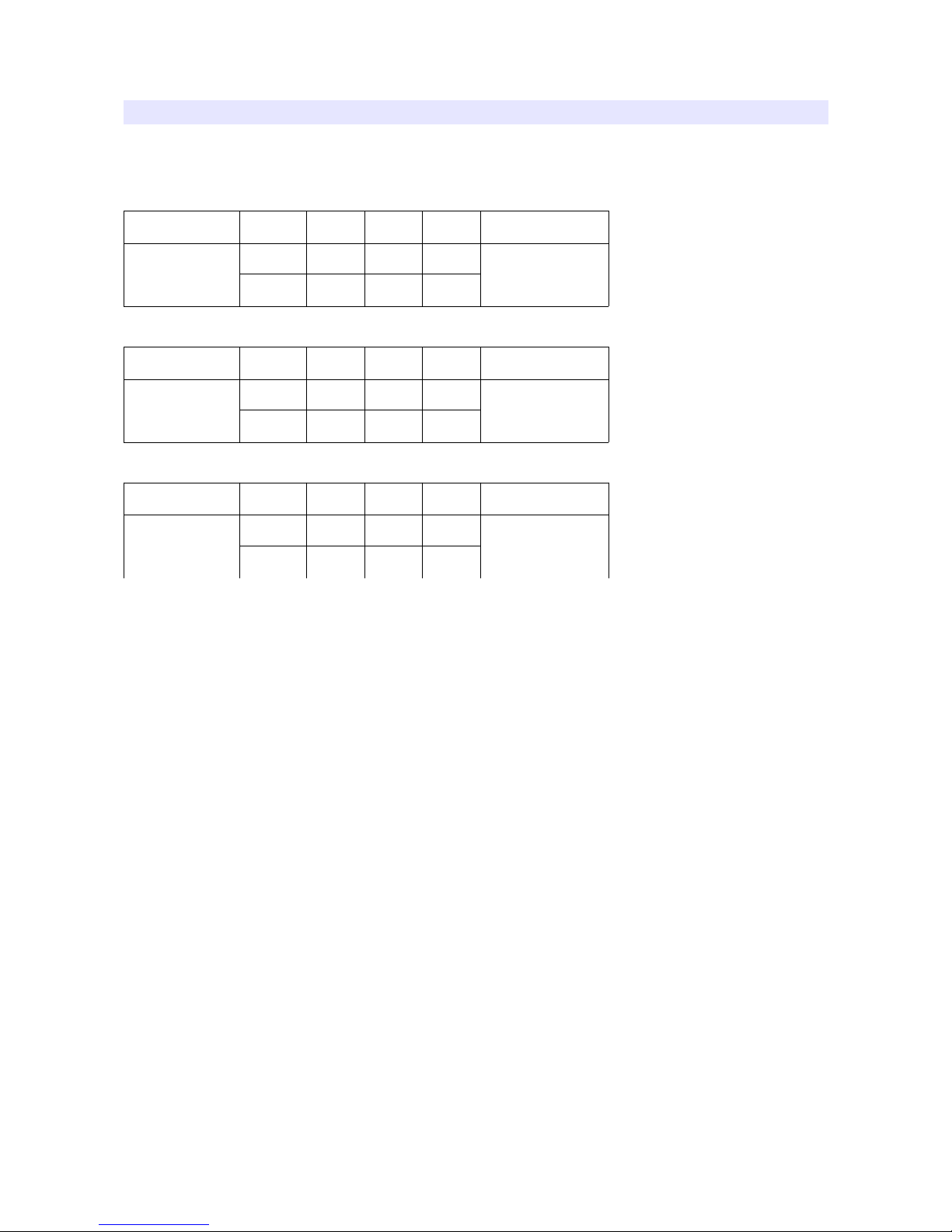
Dimensions
MODEL Unit W H D
Remark
BEM-182
mm 459.0 264.0 38.3
without Stand
inches 18.0 10.3 1.5
MODEL Unit W H D
Remark
BEM-212
mm 523 299 38
without Stand
inches 20.5 11.7 1.5
MODEL Unit W H D
Remark
BEM-242
mm 583 330 38
without Stand
inches 22.8 12.9 1.5
35
Page 36
Troubleshooting
Try these if you have trouble in using the monitor. Call for Service if you can't solve the problem
even after you tried these solutions.
Symptom Solution
Power isn't turned on
Check Connectivity of Power Cable between Outlet and the Monitor.
Press and Hold Power button for more than one second.
Try with Other Monitor or Electric Device using the same Power Cable.
Check if battery voltage is above 12V when the monitor powered by battery.
Screen is Black and All Button Lights are
On
in startup process
Reconnect the Power and Restart the Monitor.
(Call for Service if the Symptom appeared more than 3 times)
Screen is Black on Startup and there's
neither BON Logo nor "No Signal"
Display, but Buttons are Working
Reconnect the Power and Restart the Monitor.
(Call for Service if the Symptom appeared more than 3 times)
There's a delay in BON Logo Display on
Startup
It is normal and No Reaction Required.
BON Logo appeared on Startup, but No
Screen Output when Input Signal
Connected
Remove Input Cable and Check if "No Signal" appears on Screen.
- restart the Monitor if you can't see "No Signal"
- Make Monitor "Factory Default" and Try again and Try again
- Check the Cable Connectivity
- Try with Different Cable
- Check the Input Format and Frequency
- Try with Different Input Device. If successful, the Failed Input Device may
Generate Non-Standard Signal (Please Inform Us its Model Name).
"No Signal" appears on the Screen
Check the Input Selection.
Make Monitor "Factory Default" and Try again.
Try with Different Input Cable.
Check the Cable Connection.
Check if the Input Format and Frequency is Supported.
Try with Different Input Device. If successful, the Failed Input Device may
Generate Non-Standard Signal (Please Inform Us its Model Name).
36
Page 37
Strange Color on BON Logo on Startup
Reconnect the Power and Restart the Monitor.
(Call for Service if the Symptom appeared more than 3 times)
the Startup Logo Color was ok but Strange
Color on Active Screen
Make Monitor "Factory Default" and Try again.
Select Test Pattern(Internal Pattern) in the menu and See if R,G,B Color is
Correct.
Check the Input Selection.
Try with Different Cable.
Check if Each Cable is correctly Connected when you use Component as Input.
Screen Position Mismatch
Make Monitor "Factory Default" and Try again.
Reconnect the Power and Restart the Monitor.
Try with Different Input Device. If successful, the Failed Input Device may
Generate Non-Standard Signal (Please Inform Us its Model Name).
No Audio Output
Check if the Volume level is 0.
Display the Audio Level Meters and See its output.
Colors look different between different
models
Give your Monitor 1 hour warmup time.
Because Different Panels have different Characteristics, Colors might look
Different.
Colors look different between same
models
Give your Monitor 1 hour warmup time.
Same Panels are not exactly same but they have a tolerance range among them by
the Panel Manufacturer, so Colors might look Different.
* The tolerance range is in Panel Standard Document included in CD
37
Page 38

Warranty Information
Free Service
If the product needs to be repaired in 12 months from the purchase.
Exceptions
• damage caused by accident, abuse, misuse, water, flood, fire, or other acts of nature or external
causes
• damage caused by service performed by anyone who is not an authorized service provider
• damage to a product that has been modified or altered without the written permission of BON
Service to be Charged
If the product needs to be repaired after 1 year and before 4 years from the purchase.
Modification of Product
Dimensions, specifications or design of the product are subject to change without prior notice for
product improvement.
Caution on Menu Operation
OSD Menu might be freezed or broken on very high-quality or complicated pictures input. In that
case, turn off the power for 5 seconds and turn it on to make Menu works.
Caution for Monitor Placement
For long lifetime and proper operation of the monitor, all surface of the monitor should not be
blocked by any material for ventilation.
Caution for Usage
This monitor is designed to be used for broadcasting purpose. Using it as PC monitor is not
recommended.
38
Page 39
Corporate Headquarters
Tresebelle-Sky 2F, 1479 Gayang-2, Gangseo-gu, Seoul, South Korea
Research / Service Center
Vision Tower 7F, 1481 Gayang-2, Gangseo-gu, Seoul, South Korea
Telephone
+82 2 2659 0333
FAX
+82 2 2659 8133
Web
http://www.bon.co.kr
Email
39
 Loading...