

BOMBARDIER Citation LS, Citation LSE, Tundra LT, Tundra LTS, 1987 Citation LS Operator's Manual
...Page 1

operator's
manual
1
414
6062
00
Page 2

model
V.I.N.
purchase date
warranty
expiry
date
To
be
completed
by dealer
at
time
of
sale
DEALER IMPRINT AREA
AFTER SALES SERVICE
The following
are
trademarks of Bombardier
Inc.
BOMBARDIER INC.
ALPINE®
FORMULA*
SAFARI*
VALCOURT,
QUEBEC
BLIZZARD®
FUTURA® SKANDIC®
CANADA,
JOE 2LO
BOMBARDIER®
GRAND
PRIX SPECIAL® SKI-DOO®
CARRY-BOOSE® MIRAGE® SONIC®
H
~
CITATION® MOTO-SKI®
SPIRIT®
ELAN®
NORDIK®
STRATOS*
Quality
ELITE®
NUVIK®
T'NT®
ESCAPADE*
OLYMPIQUE®
TUNDRA*
Service
EVEREST® ROTAX®
Litho'd in Canada
®*Trademarks
of
Bombardier Inc. All rights reserved © Bombardier Inc.
Page 3

FOREWORD
__________________
_
The operator manual and the Snowmo-
bile Safety Handbook
have
been prepa-
red
to acquaint the owner I operator of
a new snowmobile
with
the various ve-
hicle controls, maintenance and safe
operating instructions.
Each
is
indispen-
sable for the proper use
of
the product,
and should
be
kept
with
the vehicle at
all times.
Should you have any questions pertain-
ing to the warranty and its application,
please consult the " Often Asked Ques-
tion"
section of this manual, or your au-
thorized dealer.
This manual
uses
the following symbols.
•
WARNING: Identifies
an
instruc-
tion which, if not followed, could
cause personal injury or death.
~CAUTION:
Denotes
an
instruction
T which, if not followed, could se-
verely damage vehicle components.
0
NOTE: Indicates supplementary in-
formation needed to fully comple-
te
an
instruction.
Although the mere reading of such in-
formation does not eliminate the hazard,
your understanding of the information
will promote its correct use .
•
WARNING: The engines and the
corresponding components iden-
tified
in
this manual should not be uti-
lized
on
product(s) other than those
mentioned
on
the cover page
of
this
manual.
The information, illustrations and com-
ponents/system descriptions contained
in
this manual are correct at time of pu-
blication. Bombardier
Inc.
however,
main-
tains a policy of continuous improvement
of
its
products without imposing upon it-
self
any
obligation to install them
on
pro-
ducts previously manufactured.
Bombardier
Inc.
reserves the right at any
time to discontinue or change specifica-
tions, designs, features,
models or equip-
ment
without
incurring obligation.
The illustrations show the typical cons-
truction of the different assemblies and,
in
all cases, may
not
reproduce the full
detail or exact shape of the parts shown,
however,
they represent parts which
have
the same or a similar function.
Most specifications
are
given
in
both me-
tric and customary units. Where precise
accuracy
is
not required, some conver-
sions are rounded to
even
numbers for
easier
use.
A shop manual
can
be
obtained for com-
plete service, maintenance and repair in-
formation.
~CAUTION:
Several components
T of this vehicle are built with parts
dimensioned
in
the metric system. Most
fasteners are metric and must not be
repalced
by
customary fasteners
or
vice
versa.
Mismatched
or
incorrect fasten-
ers
could cause damage to the vehicle
or
possible
personal
injury.
Page 4

SAFETY
MEASURES
__________________________
_
Observe
the
following
precautions:
• Throttle mechanism should
be
check-
ed
for free movement before starting
engine.
• Engine should
be
running only when
belt guard and/or pulley guard
is
se-
cured
in
place.
• Never run the engine
without
drive
belt installed. Running
an
unloaded
engine can prove to
be
dangerous.
• Never run the engine when the track
is
raised
off
the ground.
• It
can
be
dangerous to
run
engine with
the hood removed.
• Gasoline
is
flammable and explosive
under certain conditions. Always ma-
nipulate
in
a well ventilated area.
Do
not smoke or allow open flames or
sparks
in
the vicinity.
If
gasoline fumes
are noticed while driving, the cause
should
be
determined and corrected
without
delay.
• Maintain your vehicle
in
top mechan-
ical condition at all times.
• Your snowmobile
is
not designed to
be
driven or operated
on
black top,
bare
earth, or other abrasive surfaces.
On
such surfaces abnormal and ex-
cessive wear
of
critical parts
is
inevi-
table.
• Your snowmobile
is
not designed to
be
operated on public streets, road
or highways.
In
most States and Pro-
vinces, it
is
considered
an
illegal oper-
ation.
• Installation of other than standard
equipment, including ski-spreaders,
bumpers, pack racks, etc., could se-
verely affect the stability and safety
of your vehicle. Avoid adding on ac-
cessories that alter the basic vehicle
configuration.
• The snowmobile engine can
be
stop-
ped
by
activating the emergency cut-
out switch, tether switch or by tur-
ning
off
the
key.
• Whenever the vehicle
is
parked out-
doors, overnight or for a long period,
it
is
suggested to protect it against
the inclemency of the weather
with
a snowmobile cover.
•
Do
not lubricate throttle and/or brake
cables and housings.
• Only perform procedures
as
detailed
in
this manual. Unless otherwise spe-
cified, engine should
be
turned
OFF
for
all
lubrication
and
maintenance pro-
cedures.
•
Clean
and
check
operation
of the
head-
light, taillight and brake light.
• These vehicles are designed for the
driver only. No provisions have been
made for a passenger.
• Should removal of a nylon lock nut
be
required when undergoing repairs/dis-
assembly,
always
replace
by
new
ones.
Tighten
as
specified
in
the applicable
Shop Manual.
PLEASE
READ
AND
UNDERSTAND
ALL
WARNINGS AND CAUTIONS
IN
THIS
MANUAL AND
ON
THE
VEHICLE.
THIS
MANUAL
SHOULD
REMAIN
WITH
THE
VEHICLE
AT
THE
TIME
OF
RESALE.
2----------------------------
Page 5

INDEX
________________________
_
THE
1987
"LIMITED
WARRANTY"
..
OFTEN
ASKED
QUESTIONS
.......................
.
LISTING
OF
AREA
DISTRIBUTORS .......................
.
HOW
TO
IDENTIFY
YOUR
SNOWMOBILE
CONTROLS/INSTRUMENTS
Throttle
lever,
brake
lever,
ignition/light switch, headlamp dimmer switch,
emergency cut-out switch, tether cut-out switch, rewind starter handle, pri-
mer,
adjustable steering handle, fuel gauge/tank
cap,
hood opening, tool box,
4
6
8
9
fuse holder, hitch . . . . . . . . . . . . . . . . . . . . . . . . . . . . . . .
10
BREAK-IN
PERIOD
Engine and belt break-in, 10 hour-inspection, check list
............
.
13
FUEL & OIL
Recommended gasoline, recommended oil, fuel mixture and mixing proce-
dure, fuel/oil mixing chart, oil injection system . . . . . . . . . . . . . . . . . .
15
PRE-START
CHECK
Check points
........................................
.
STARTING
PROCEDURE
Manual starting, electric starting, before riding, emergency starting
....
LUBRICATION
Frequency, steering mechanism, drive axle, slide suspension, chaincase oil
level, oil injection system, drive pulley
.........................
.
MAINTENANCE
Chart, belt guard removal, drive belt removal and installation, drive belt con-
dition, new drive belt, brake condition, brake adjustment, brake light switch
adjustment, spark plug, battery, suspension condition, stopper strap condi-
tion, suspension adjustment, track condition, track tension and alignment,
drive pulley, steering mechanism, steering adjustment, muffler attachment,
engine mount nuts, carburetor adjustment, oil injection system, fan belt, head-
lamp beam aiming, bulb replacement, general inspection
..........
.
STORAGE
Track,
suspension, ski, controls, chaincase, drive pulley, engine and primer
lubrication, fuel tank and carburetor, battery, chassis, general inspection, sus-
pension stopper strap . . . . . . . . . . . .
......................
.
PRE-SEASON
PREPARATION
Pre-season preparation chart,
...........................
.
TROUBLE
SHOOTING
GUIDE
.........
.
TOOLS
......................
.
SPECIFICATIONS
.............
.
WIRING
DIAGRAMS
...
Sl
METRIC
INFORMATION
GUIDE
..
18
18
20
22
34
37
38
40
41
45
47
----------------------------------------------------3
Page 6

THE
1987
SNOWMOBILE
LIMITED
WARRANTY----------
1
-PERIOD
BOMBARDIER® INC. as manufacturer,
warrants
FROM THE
DATE
OF
FIRST
CONSUMER SALES, every
1987
BOMBARDIER snowmobile, sold as NEW AND
UNUSED, and predelivered by an authorized BOMBARDIER dealer
for
a period of:
• 12
consecutive
months.
2 -
WHAT
BOMBARDIER
WILL
DO
BOMBARDIER
will
repair and/or replace,
at
its option,
components
defective
in material and/or
workmanship
(under normal use and service,)
with
a genuine
BOMBARDIER
component without
charge
for
parts
or
labour,
at
any
authorized
BOMBARDIER dealer during said
warranty
period.
3-
CONDITION
TO HAVE
WARRANTY
WORK
PERFORMED
Present
to
the
servicing dealer,
the
hard
copy
of
the
BOMBARDIER
Warranty
Registration card or
proof
of
purchase received by
the
customer
from
the
sel-
ling dealer
at
time
of
purchase.
4 -
WARRANTY
TRANSFER
This
warranty
is transferable
to
subsequent owner(s)
for
remainder
of
warran-
ty
period
from
original
date
of
sale.
5 -
EXCLUSIONS -ARE
NOT
WARRANTED
• Normal
wear
on all
items
such
as,
but
not
limited
to:
- drive belts - bulbs
- slider shoes - runners on skis
- spark plugs
• Replacement parts and/or accessories
which
are
not
genuine BOMBARDIER
parts
and/or accessories.
• Damage resulting from installation
of
parts other
than
genuine BOMBARDIER
parts.
• Damage caused by failure
to
provide proper maintenance as detailed in
the
Operator's Manual. The labour, parts and lubricants
costs
of
all maintenance
services, including tune-ups and
adjustments
will
be charged
to
the
owner.
• Vehicles designed and/or used
for
racing purposes.
•
All
optional accessories installed on
the
vehicle.
(The normal
warranty
policy
for
parts and accessories,
if
any, applies).
• Damage resulting
from
accident, fire or
other
casualty, misuse, abuse
orne-
glect.
• Damage resulting
from
operation
of
the
snowmobile
on surfaces
other
than
snow.
• Damage resulting
from
modification
to
the
snowmobile
not
approved in
writ-
ing by BOMBARDIER.
4----------------------------
Page 7

• Losses incurred by
the
snowmobile
owner
other
than
parts and labour, such
as,
but
not
limited to, transportation,
towing,
telephone calls, taxis, or any
other incidental or consequential damage.
6 -
BATTERY
WARRANTY:
• 12 consecutive months. (Pro-rated)
100%
warranty
coverage
will
start
on
the
date
the
snowmobile
was pur-
chased and run
to
the
following
April
30th.
The remainder
of
the
12
month-
period
will
be pro-rated as follows:
-
50%
from
April
30th
to
December 1st.
-
40%
from
December 1st
to
December 31st.
-
30%
from
January
1st
to
end
of
warranty.
7 -
EXPRESSED
OR
JMPLIED
WARRANTIES
This
warranty
gives
you
specific
rights,
and
you
may
also
have
other
legal
rights
which
may
vary
from
state
to
state,
or
province
to
province.
Where
applicable
this
warranty
is
expressly
in
lieu
of
all
other
expressed
or
im-
plied
warranties
of
BOMBARDIER,
its
distributors
and
the
selling
dealer,
including
any
warranty
of
merchantability
or
fitness
for
any
particular
pur-
pose;
otherwise
the
implied
warranty
is
limited
to
the
duration
of
this
war-
ranty.
However,
some
states
or
provinces
do
not
allow
limitations
on
how
long
an
implied
warranty
lasts,
so
the
above
limitation
may
not
apply.
Neither
the
distributor,
the
selling
dealer,
nor
any
other
person
has
been
authorized
to
make
any
affirmation,
representation
or
warranty
other
than
those
contained
in
this
warranty,
and
if
made,
such
affirmation,
representation
or
warranty
shall
not
be
enforceable
against
BOMBAR-
DIER
or
any
other
person.
Some
states
or
provinces
do
not
allow
the
exclusion
or
limitation
of
inci-
dental
or
consequential
damages,
so
the
above
limitation
or
exclusion
may
not
apply.
BOMBARDIER
INC.
reserves
the
right
to
modify
its
warranty
policy
at
any
time,
being
understood
that
such
modification
will
not
alter
the
war-
ranty
conditions
applicable
to
vehicles
sold
while
the
above
warranty
is
in
effect.
8 - CONSUMER ASSISTANCE
If
a servicing problem
or
other
difficulty
occurs,
we
suggest
the
following:
1.
Try
to
solve the problem
at
the dealership
with
the Service Manager or Owner.
2.
If
this
fails,
contact
your area
distributor
listed in the Operator's Manual.
3. Then
if
your grievance still remains unsolved, you may
write
to
us:
Bombardier Inc.
Service
Department
Recreational Products Division
Valcourt (Quebec), Canada, JOE 2LO
February
1986
Bombardier Inc.
Valcourt (Quebec), Canada,
JOE
2LO
®*Trademarks
of
Bombardier Inc.
---------------------------5
Page 8

OFTEN ASKED
QUESTIONS
________________________
__
0:
Why must my snowmobile
be
registered? After
all
I do
have
my original invoice
as
proof of when I purchased my snowmobile.
A:
Your
warranty is valid
at
any authorized dealer
of
the product.
Your
registra-
tion is the key element in providing the servicing dealer with the necessary data
to complete warranty claim forms. This information
is
also used to notify owners
in the event
of
a safety recall.
0: Who should send the registration card to Bombardier
Inc.?
A:
The
dealer. However, the customer
must
make sure that
it
has been sent.
The
company
might
contact
you should your vehicle be recalled
or
in case
of
a particular warranty campaign.
0:
I bought
my
snowmobile
in
O'King County but I snowmobile
in
Washington Coun-
ty.
Can
the dealer
in
Washington County accept to perform warranty work on my
snowmobile?
A:
Yes,
any authorized dealer in North America can perform warranty repairs,
providing the customer warranty registration card is presented.
0:
Where can I find information on the lubrication and maintenance of my snow-
mobile?
A: In this Operator Manual provided with the vehicle
at
the time
of
first
sale.
0:
Will the entire warranty
be
void or cancelled, if I do not operate or maintain my
new snowmobile exactly
as
specified
in
the Operator's Manual?
A:
The
warranty
of
the
new
snowmobile cannot be
"Voided"
or
"Cancelled':
However,
if
a particular failure is caused by operation
or
maintenance other than
is shown in the Operator Manual, THAT failure may
not
be covered under war-
ranty.
This
includes service work performed by the customer, especially the crit-
ical adjustments to ignition, timing, carburation
and
oil
injection/or
oil
mixture.
0:
Would you give some examples of abnormal
use
or strain, neglect or abuse?
A: These terms are general
and
overlap each other in
areas.
Some specific ex-
amples may include: running the machine
out
of
oil, chain failure caused by
a lack
of
lubrication, operating the machine with a broken
or
damaged part which
causes another
part
to fail,
and
so
on.
If
you have any specific questions on
operation
or
maintenance, please
contact
your dealer for advice.
6--------------------------
Page 9

0:
What
costs
are
my responsibility during the warranty period?
A:
The
customer's responsibility includes all costs
of
normal maintenance ser-
vices,
non-warranty repairs, accidents
and
collision damage, as well as
oils,
and
spark plugs,
and
incidental
or
consequential damages costs as explained in the
warranty.
0:
Are
"Genuine"
Bombardier replacement parts used
in
warranty repairs covered
by
warranty?
A:
Yes.
When installed by an authorized
dealer,
any
"genuine"
Bombardier
part
used in warranty repairs assumes the remaining warranty that exists on the ma-
chine.
0:
If I sell my snowmobile within the warranty period, will the new owner qualify
for the balance of the warranty?
A:
Yes,
provided the unit has already been registered with the manufacturer.
Note that the change
of
ownership
card
in this manual should be completed
and
sent
to
Bombardier Inc.
0:
How can I receive the best owner assistance?
A:
The
satisfaction
and
goodwill
of
the owners
of
Bombardier products are
of
primary concern to your dealer
and
Bombardier Inc. Normally, any problems
that arise in connection with the sales transaction
or
the operation
of
your snow-
mobile will be handled by your Dealers Sales
or
Service Departments. It is reco-
gnized, however, that despite the best intentions
of
everyone concerned, mis-
understandings will sometimes occur.
If
you have a problem that has
not
been
handled to your satisfaction through normal channels, we suggest that you dis-
cuss your problem with a member
of
dealership management. Frequently, com-
plaints are the result
of
a breakdown in communications
and
can quickly be re-
solved by a member
of
the dealership management.
If
the problem already has
been reviewed with the Sales Manager
or
Service Manager,
contact
the Dealer
himself
or
the General Manager.
-----------------------------7
Page 10

LISTING
OF AREA
DISTRIBUTORS
______________________
__
CANADIAN
DISTRIBUTORS
Quebec Branch
1350 Nobel
Boucherville, Quebec, J4B 1 A 1
(514) 655-6121
Province of Quebec
Ontario Branch
230 Bayview Drive
Barrie, Ontario, L4N 4Y8
(705) 728-8600
Province of Ontario
Technical office
P,O.
Box
7060
Riverview, New Brunswick,
E1
B 1
VO
(506) 386-6117
Atlantic Region
BROOKS
EQUIPMENT LIMITED
1616 King, Edward Street
P.O.
Box 985
Winnipeg, Manitoba,
R3C
2V8
(204) 633-7247
British Columbia, Manitoba, Saskatchewan,
Alberta, Yukon
CHARLES
R.
BELL
LIMITED
Newfoundland, Labrador
Offices
- Riverside Drive
P.O.
Box
1050
Corner Brook, Newfoundland, A2H 6J3
(709) 634-3533
-
81
Kenmount
Road
P.O.
Box
8127
St-John's, Newfoundland, A 1 B
3N
1
(709)
722-6700
HUDSON'S
BAY
CO.
LTD.
165 Hymus Blvd
Pointe-Claire, Quebec,
H9R 1 G2
(514) 697-8500
North-West Territories, Franklin District &
Keewatin
AMERICAN
DISTRIBUTORS
BOMBARDIER
CORPORATION
All States (excluding Alaska)
SERVICE
OFFICES
- East Main Street
Road
Malone, New York 12953
(518) 483-4411
Technical office
(506) 386-6117
- 4505 West Superior Street
P.O.
Box
16106
Duluth, Minnesota 55816-016
(218) 628-2881
-
P,O.
Box 1569
Idaho Falls, Idaho,
83403
(208) 529-9510
NATIONAL
SALES
OFFICE
-O'Hare
Lake
Plaza
2350 Devon Avenue
Suite 150
Des Plaines, Illinois
60018
(312) 298-9540
MILLER
EQUIPMENT AND
RECREATIONAL
CENTER
1 049 Whitney
Road
Anchorage, Alaska 99501
(907) 274-9513
Alaska
8----------------------------
Page 11

HOW
TO
IDENTIFY
YOUR
SNOWMOBILE----------
The main components of your snowmo-
bile (engine, track(s) and frame)
are
iden-
tified
by
different serial numbers. It may
sometimes become necessary to locate
these numbers for warranty purposes or
to trace your snowmobile
in
the event of
theft.
A002005010
A005007003
Vehicle serial
number
meaning:
0000
00000
--r-
Model no
Vehicle no
A000000013
A003002013
Engine serial
number
0
NOTE: We strongly recommend that you take note of all the serial numbers
on your vehicle and supply them to your insurance company. It will surely
help
in
the event a snowmobile
is
stolen.
-----------------------------9
Page 12

CONTROLS/INSTRUMENTS
___
_
B
I
K
AJ
Throttle Control Lever
8)
Brake Control
Lever
CJ
Ignition/Light Switch
D) Head/amp Dimmer Switch
E)
Emergency Cut-Out Switch
A003007002
A)
Throttle
Lever
Located
on
right side of handlebar. When
compressed, it controls the engine speed
and the engagement
of
the transmission.
When released, engine speed returns au-
tomatically to idle.
B) Brake Lever
Located on the left side
of
handlebar.
When compressed, the brake
is
applied.
When released, it automatically returns
to its original position. Braking effect
is
proportionate to the pressure applied
on
the lever and to the type
of
terrain and
its
snow
coverage.
C)
Ignition/Light
Switch
The
lights
are
automatically
ON
whenever
the engine
is
running.
FJ
Tether Cut-Out Switch
G)
Rewind Starter Handle
HJ
Primer
/}
Adjustable steering handle
J)
Fuel gauge/tank cap
KJ
Hood Opening
Manual
starting
ON
~,QFF
A
c
H
K
J
~-NOT
IN
USE
A002007002
Key
operated, 3 position switch.
To
start
engine, first turn
key
fully clockwise to
START
position and hold. Return
key
to
ON
popition
immediately when engine
has
started.
To
stop engine, turn
key
counter-
clockwise
to
OFF
position. The 3rd po-
sition
is
not
in
use.
10-------------------------
Page 13

Electric
starting
OFF
f1':i~oN
~START
A002007002
Key
operated, 3 position switch.
To
start
engine,
turn
key
fully clockwise to
START
position and hold. Return
key
to
ON
po-
sition immediately when engine
has
star-
ted.
To
stop engine, turn
key
counter-
clockwise to
OFF
position.
-.r
CAUTION: Holding key in START
T position when engine has started
could damage
starter
mechanism.
D) Headlamp
Dimmer
Switch
The dimmer switch, located
on
left side
of handlebar, allows correct selection of
headlamp beam.
To
obtain high or low
beam simply flick switch.
E)
Emergency Cut-Out
Switch
A push pull type switch located
on
the
right side
of
the handlebar.
To
stop the
engine
in
an
emergency, push the but-
ton to the lower
off
position and simul-
taneously apply the brakes.
To
start en-
gine, button must
be
at the upper
ON
position.
+
ON
t
OFF
~~
Upper position
before starting
A017006004
Lower position
to stop engine
•
WARNING: For
safety
reasons,
the
emergency
cut-off
switch
is
easily accessible; be careful
not
to
op-
erate
it
inadvertently.
The
driver of this vehicle should familiar-
ize
himself with the function
of
this de-
vice
by
using it
several
times
on
first out-
ing.
Thereby being mentally prepared for
emergency situations requiring its use .
•
WARNING: If the switch has been
used in
an
emergency
situation
the
source
of
malfunction
should be
determined
and
corrected before restar-
ting
engine.
F)
Tether
Cut-Out
Switch
Attach tether cord to wrist or other con-
venient location then snap tether cut-out
cap over receptacle before starting en-
gine.
If emergency engine
"shut
off"
is
re-
quired, completely pull cap from safety
switch
and
engine power will
be
automa-
tically shut
"off".
0
NOTE: The cap must
be
installed
on
the safety switch at
all
times
in
order to operate the vehicle .
•
WARNING:
If
the
switch
is
used
in an emergency
situation
the
source
of
malfunction
should be de-
termined and corrected before restart-
ing engine.
G) Rewind
Starter
Handle
Auto rewind type located
on
right hand
side
of
vehicle.
To
engage mechanism,
pull handle.
--------------------------11
Page 14

H)
Primer
A push-pull button. Pull and push but-
ton (2-3 times)
to
activate primer. The
primer should always
be
used
for
cold
engine starts. After engine
is
warm how-
ever,
it
is
not
necessary
to
use primer
when
starting.
I)
Adjustable Steering Handle
- Remove steering cover.
-
Loosen
the
four
(4)
retaining
screws.
- Adjust the handle to the desired posi-
tion .
•
WARNING: Do not adjust too
high
as
the
brake lever may contact
the
windshield
when
turning.
- Lock the steering handle
in
place
by
tightening the four (4) retaining screws
to
26
N•m
(19
lbf•ft).
- Reinstall steering cover.
J)
Fuel
Gauge/Tank
Cap
Unscrew fuel tank cap and withdraw dip-
stick
to
check fuel level.
•
WARNING: Never use a lit match
or open flame to check fuel level.
K)
Hood
Opening
Pull
down the latches to unlock the hood
from the anchor.
0
NOTE: Always lift hood gently up
until stopped by restraining device.
•
WARNING: It
is
dangerous to
run
an
engine with the
hood
open un-
fastened or removed.
Tool Box
Located under the hood.
To
gain access,
tilt
hood. Ideal location
for
spare rope,
first aid kit, etc.
Fuse
Holder
(Electric
Starting
Only)
Starting system
is
protected
with
a
30
amperes rated fuse. Fuse holder
is
loca-
ted close
to
the battery. If starter does
not work, check fuse condition and if re-
quired replace with one
of
the same val-
ue.
Hitch
(Tundra
models
only)
Carry-boose
adapter
~
A007007005
0
NOTE:
For
convenience, a carry-
boose adapter
is
supplied
in
the tool
box.
•
WARNING:
When
towing a sled
or trailer, always ensure
to
lock
the hook
or
plate type attachment with
the
hair pin.
12------------------------
Page 15

Trailers or sleds towed behind a snow-
mobile should always
be
loaded
in
a way
to obtain the lowest possible center of
gravity.
Use
a rigid
tow
bar when pulling
a tow
sled
behind
your
snowmobile.
When
you are pulling passengers
in
a trailer or
tow sled,
use
moderate speed and avoid
rough terrain for their safety. Also, have
all
passengers get out of a towed vehicle
and walk across all roads.
BREAK-IN PERIOD
______
_
Engine
This Bombardier-Rotax snowmobile en-
gine,
has
a critical
break-in
period require-
ment before running the vehicle at full
throttle.
Engine
manufacturer strongly
rec-
ommends
10
to
15
operating
hours.
Max-
imum throttle
should
not
exceed
3/4, how-
ever,
brief full acceleration
and
speed
vari-
ations contribute to a good
break-in.
Con-
tinued wide open throttle accelerations,
prolonged cruising speeds, and lugging
are detrimental during the break-in pe-
riod.
Citation LS/LSE, Tundra, Tundra
LT
0
NOTE:
For
the break-in period on-
ly,
450
ml
(16
oz)
of Bombardier
Snowmobile Injection oil should
be
ad-
ded
to
fuel
for the first full
fuel
tank filling.
Tundra LTS
0
NOTE:
Recommended fuel/oil ratio
is
40:1 during engine break-in pe-
riod.
This
will
assure
additional
protection
dur-
ing the initial engine break-in.
._,
CAUTION: Remove
and
clean spark
T
plug
after engine break-in.
Belt
A new drive belt requires a break-in pe-
riod of
25
km
(15
miles).
10-Hour
Inspection
As
with any precision piece of mechani-
cal equipment, we suggest that after the
first 10 hours of operation or
30
days
after the
purchase,
whichever comes first,
that your vehicle
be
checked
by
your
dealer. This inspection will give you the
opportunity to discuss the unanswered
questions you may have encountered
during the first hours of operation.
Re-
member that it
is
easier to remedy at
this time than to allow the snowmobile
to operate until a possible failure occurs.
The
10
hour inspection
is
at
the
ex-
pense
of
the vehicle owner.
----------------------------13
Page 16

10-HOUR
INSPECTION
CHECKLIST
./
Engine
timing
Fan
belt tension
Spark plug condition: (Remove and clean)
Carburetor
adjustment
Oil injection
pump
adjustment
(not applicable
to
Tundra
LTS)
Battery
electrolyte level (electric starting only)
Engine
mount
nuts
Muffler
attachment
Chaincase oil level
Injection system oil level (not applicable
to
Tundra
LTS)
Brake operation and lining
condition
Ski alignment (runners condition)
Steering arm, retorque
to
50
N•m
(37
lbf•ft)
Handlebar bolts, retorque
to
26
N•m
(19
lbf•ft)
Pulley alignment and drive belt condition
Track condition, tension and alignment
Lubrication (steering, suspension, drive axle)
Electrical
wiring
(loose connections, stripped wires, damaged insula-
tion),
tighten
all loose bolts,
nuts
and linkage
Operation
of
lighting system (HI I
LO
beam, brake light, etc.),
test
operation
of
emergency
cut-out
switch
and
tether
switch
We
recommend
that
you have your
dealer
sign this inspection list.
Date
of
10 hour inspection
Dealer signature
14----------------------------------------------
Page 17

FUEL &
OIL
_________
_
Recommended
Gasoline
Use
regular leaded or unleaded gasoline
available from all service stations.
'W'
CAUTION: Never experiment
with
T different fuel or fuel ratios. Never
use naphtha, methanol, gasohol or sim-
ilar products.
•
WARNING: Never
"top
up"
the
gas
tank
before placing the vehi-
cle in a warm area.
At
certain temper-
atures, gasoline will expand and over-
flow. Always wipe
off
any gasoline spil-
lage
from
the
snowmobile.
Recommended
Oil
Citation LS/LSE, Tundra, Tundra
LT
Use
"Bombardier Snowmobile Injection
Oil"
(P/N
496
0133
00-
1 liter).
Tundra LTS
Use
BLIZZARD oil
(P/N
496
0135
00-
500
ml).
Available from your authorized dealer,
this type of oil will flow at temperatures
as
low
as
minus
40°C
(-40°F).
It
is
a blend of specially selected base
oils and additives which provides out-
standing lubrication, engine cleanliness
and minimum spark plug fouling.
Should "Bombardier Snowmobile Injec-
tion
Oil"
is
unavailable, substitute with
BLIZZARD oil or vice versa.
'W'
CAUTION: Never use outboard or
T
straight
mineral oils.
Oil
Injection
System
Citation LS/LSE, Tundra, Tundra
LT
Always maintain a sufficient amount of
"Bombardier Snowmobile Injection Oil"
in
the injection oil tank.
'W'
CAUTION:
Check
level and refill
T every
time
you refuel.
0
NOTE:
For
the break-in period on-
ly,
450
ml
(16 oz.) of Bombardier
Snowmobile Injection
Oil
should
be
add-
ed
to fuel for the first full fuel tank filling.
This will assure additionnal protection
during the initial engine break-in.
----------------------------15
Page 18

Fuel
Mixture
Ratio &
Mixing
Procedure
Tundra
LTS
Oil
must
be
added to the gasoline
in
pre-
measured
amounts then both
oil
and
gas-
oline should
be
thoroughly mixed togeth-
er
before fueling the tank.
The importance of using the correct fuel
mixture cannot
be
overstressed. An in-
correct fuel ratio results
in
serious engine
damage.
Recommanded
fuel
ratio
is
50:1
(40:1 during break-in period).
Sl
UNITS
500
ml oil to 25 liters=
50:1
IMPERIAL
UNITS
16
oz
oil to 5 imp.
gal.=
50:1
or
500
ml oil to 5
112
imp. gal.=
50:1
U.S.
UNITS
13
oz
oil to 5
U.S.
gal.=
50:1
0
NOTE:
To
facilitate fuel mixing, oil
should
be
kept at room tempera-
ture.
To
mix the gasoline and oil always use
a separate clean container.
Never
mix di-
rectly
in
your snowmobile tank.
For
best
results, acquire
two
containers, either
plastic ou metal. Draw from one until
empty then use the second one .
•
WARNING: Gasoline
is
flammable
and explosive under certain con-
ditions.
Always
manipulate
in
a well
ventilated area. Do not smoke or allow
open flames or sparks
in
the vicinity.
If gasoline fumes are noticed while dri-
ving, the cause should be determined
and
corrected without
delay.
Never add
fuel while the engine
is
running. Avoid
skin
contact with fuel at below freezing
temperatures.
1.
Pour
approximately 4 liters (one gal-
lon) of gasoline into a clean contain-
er.
2.
Add the full amount of
oil
required for
the mixture.
3.
Replace the container cap and shake
the container thoroughly.
4.
Add the remainder of the gasoline.
5.
Once
again
thoroughly agitate the con-
tainer.
Then
using
a funnel with a
FINE
MESH
SCREEN
to prevent the entry
of foreign particles, pour the mixture
into the snowmobile tank.
•
WARNING:
To
prevent fuel spill-
age,
a funnel must always
be
used
when
filling
the
gas tank.
0
NOTE: When
using
pre-mixed
fuel,
always shake the container thor-
oughly
as
the
oil
has
a tendency to
settle.
16--------------------------
Page 19

FUEUOIL MIXING
CHARTS
(50.1 ratio)
METRIC (SI)
25:;:-
..
·····
24
20
,.
"
Gas
"
I liters)
,.
,
12
10
·~++1-r~~+~+H+~++rl~
50
100 150
200
250
300 350
400
450
500
OIL
lmll
IMPERIAL
5
,,., ,.,.
,.,
..................... .
Gas
limp. gal. I 3
H++-1H+t.-!'++H++-'H--1
5
6.5
10
1516
OIL limp. ozl
UNITED STATES
Gas
IU.S. gal. I 3
t-++-H+-¥t++-t-+*l-l
5
10
OIL IU.S. ozl
A000000006
USE
BLIZZARD OIL
---------------------------17
Page 20

PRE-START CHECK
Check
Points
•
ACTIVATE
THE
THROTTLE
CONTROL
LEVER
SEVERAL
TIMES to check that
it operates easily and smoothly. The
throttle control lever
must
return to
idle position
when
released.
• Check fuel level.
• Check injection oil level.
• Check that the skis and the track are
not frozen to the ground or snow sur-
face and that steering operates freely.
STARTING
• Activate the brake control lever and
make sure the brake fully applies be-
fore the brake control lever touches
the handlebar grip.
• Verify that the path ahead
of
the ve-
hicle
is
clear of bystanders and obsta-
cles.
•
WARNING: Only start your snow-
mobile once
all
components
are
checked and functioning properly.
PROCEDURE
__________________________
_
Test
throttle control lever.
Check that the emergency cut-out switch
is
in
the
ON
position.
A017006004
Upper
position
before starting engine
Ensure the tether
cut-out
cap
is
in
posi-
tion and that the cord
is
attached to your
clothing.
Activate the primer (2 or 3 times).
0
NOTE:
The use
of
the primer
is
not
necessary when the engine
is
warm.
Manual
Starting
Insert the
key
in
the ignition and turn to
ON
position.
Grasp manual starter handle firmly and
pull slowly until a resistance
is
felt then
pull vigorously. Slowly release the rewind
starter handle .
•
WARNING: Do not apply throttle
while starting.
Electric
Starting
'W'
CAUTION: Never operate your
T snowmobile with the battery re-
moved
or
disconnected. As it reduces
voltage fluctuations, operating vehicle
without battery might cause instru-
ments
or
bulbs failure.
Insert
key
in
ignition switch.
Turn ignition
key
clockwise until starter
engages.
18---------------------------
Page 21

...,.
CAUTION:
To
avoid
starter
over-
T heating, the cranking period should
should never exceed
30
seconds and
a rest period should be observed be-
tween the cranking cycles
to
let starter
cool
down.
Release
key
immediately when engine
has started. If engine does not start
on
first try,
key
must
be
turned fully back
to
OFF
each time.
Before Riding
Check operation
of
the emergency cut-
out switch, and tether switch. Restart
engine.
•
WARNING: If engine does not shut-
off
when applying the emergency
cut-out
switch
and or when pulling the
tether
cut-out
cap, stop the engine by
turning
off
the
ignition
key.
Do
not
op-
erate
the
vehicle further, see your au-
thorized dealer.
Allow the engine to warm before oper-
ating at full throttle.
Emergency
Starting
Should the rewind starter rope fray and
break, the engine can
be
started with
an
emergency starter
rope,
supplied with
the tool kit.
•
WARNING: Do
not
start
the
ve-
hicle by the drive pulley unless
it
is
a true emergency situation, have the
vehicle repaired
as
soon
as
possible.
Remove
the belt guard from
vehicle.
(See
"Maintenance section").
Assemble the handle to the emergency
starting rope and wind the rope tightly
around the drive pulley.
0
NOTE: The spark plug socket can
be
used
as
an
emergency starter
grip.
Citation
LS/LSE
Use
starter clip supplied
in
the tool box.
Tundra, Tundra LT/LTS
Sliding
half
Roller
guard
A017003018
•
WARNING: Do
not
wind
starting
rope around your hand. Hold rope
by
the
handle only.
A007003030
Start
as
per manual starting procedure .
•
WARNING: When starting the ve-
hicle
in
an
emergency situation by
the drive pulley, do not reinstall the belt
guard.
--------------------------19
Page 22

LUBRICATION
________
_
Frequency
Routine maintenance
is
necessary for
all
mechanized products,
and
the snowmo-
bile
is
no
exception. A weekly vehicle ins-
pection contributes to the life span of
the snowmobile
as
well
as
retains safe
and dependable operation.
Its recommended that the steering sys-
tem
and
suspension
be
lubricated month-
ly
or every
40
hours
of
operation. If the
vehicle
is
operated
in
wet snow or
in
sev-
ere
conditions these items should
be
lu-
bricated more frequently.
0
NOTE:
When lubricating
grease
fit-
tings, grease until grease appears
at joints. Always
use
low temperature
grease
(P/N
413
7056
00) .
•
WARNING:
Only
perform
such
pro-
cedures
as
detailed
in
this
manual.
It
is
recommended that dealer assis-
tance
be
periodically
obtained
on
other
components/systems
not
covered
in
this
manual.
Unless
otherwise
specified,
en-
gine
should
be
turned
OFF
for
all
lubri-
cation
and
maintenance
procedures.
Steering
Mechanism
•
WARNING:
Do
not
lubricate
throt-
tle and/or
brake
cables
and
hous-
ings.
Lubricate the ski legs at grease fittings
until new grease appears at joints. Coat
spring slider cushion with grease.
Oil
spring coupler bolts, ball joints and
steering column bushings.
Slide
Suspension
Citation
LS/LSE
A003005012
This suspension type does not require
any lubrication.
20
________________________
__
Page 23

Tundra, Tundra LT/LTS
Lubricate front & rear arms at grease fit-
tings with low temperature grease
only.
(P/N
413
7056
00).
Chaincase
Oil Level
Check the
oil
by
removing the chaincase
plug.
Filler plug
The oil should
be
level
with the bottom
of
the
oil
level
orifice.
Refill
as
required
using Bombardier chaincase
oil
(P/N
413
8019
00
- 200 ml).
0
NOTE:
The
chaincase oil capacity
is
approximately 200
ml
(7
oz.).
Oil Injection System
(Not
applicable
to
Tundra
L TS)
Always maintain a sufficient amount of
Bombardier Snowmobile Injection
Oil
in
the injection
oil
tank.
,.,.
CAUTION: Check
level
and
refill
T every time
you
refuel.
Drive Pulley
The
drive pulley
is
lubrication
free.
------------------------21
Page 24

MAINTENANCE
______________
__
The following Maintenance Chart indi-
cates regular servicing schedules to
be
performed
by
yourself or your authorized
dealer. If these services are performed
as
suggested, your snowmobile will give
many years of low-cost
use.
MAINTENANCE
CHART
Drive
belt
condition
Brake
condition
Brake
adjustment
Spark plug
Battery
(electric starting)
Suspension
condition
Suspension
stopper
strap
condition
Suspension
adjustment
Track
condition
Track
tension
and
alignment
Drive pulley
Steering
mechanism
Steering
adjustment
Muffler
attachment
Engine
mount
nuts
Carburator
adjustment
•
WARNING: Only perform such pro-
cedures
as
detailed
in
this manual
It
is
recommended
that
dealer assis-
tance be periodically obtained
on
other
components/systems not covered
in
this
this manual. Unless
otherwise
speci-
fied, engine should be turned OFF for
all
lubrication and maintenance proce-
dures.
E
E
0~
0
0
OJ
0
roo
Ol
lO
~
(1J
=
~~E
Q.
>~E
~~E
roM
B
:>2
OJ-"'
..C:::OJ_,
OJ
>0
- >
2
OJ
ito
COJo
u
~o
~
~"
~~o
c
OJO
OJ
>N
ON
oro
0
OJ-
a:
Injection oil
filter
condition
(not
applicable
to
Tundra
LTS)
Oil injection pump adjustment (not applicable
to
Tundra
LTS)
Fan
belt
Headlamp beam aiming
0
NO!E:
The ten hour inspection
is
a very important part of proper service and
ma1ntenance.
22--------------------------
Page 25

Belt Guard Removal
•
WARNING: Belt guard should al-
ways
be
in
place when engine
is
running.
A.
Raise
the hood and pull both retaining
pins out.
B.
Remove the guard.
Drive Belt Removal and
Installation
•
WARNING: Never start
or
run
en-
gine
without
the drive belt ins-
talled. Running an unloaded engine
is
dangerous.
1.
Tilt the hood
and
remove the belt guard.
2.
Unlock and
raise
driven pulley support.
1 ° Pull hair pin
3. Open the driven pulley
by
twisting and
pushing the sliding half. Hold
in
fully
open position.
1 ° Twist clockwise
2° Push
Driven
pulley
4. Slip the belt over the
top
edge
of
the
sliding half.
---------------------------23
Page 26

5.
Slip the belt
out
from the drive pulley
and remove completely from vehicle.
Drive pulley
A003003007
To
install the drive belt, reverse the pro-
cedure, however
pay
attention to the fol-
lowing:
The maximum drive belt life span
is
ob-
tained when the belt has the proper ro-
tation direction. Install it so the printed
information on the belt
is
in
the way to
be
read when standing face to pulleys.
CORRECT
Identification
Aoo1oo3oo2 STANDING
FACE
TO
PULLEYS
INCORRECT
t
Identification
Aoo1oo3oo3
STANDING
FACE
TO
PULLEYS
,.,.
CAUTION: Do not force
or
use
T tools to pry the belt into place,
as
this could cut
or
break the cords
in
the belt.
Drive Belt Condition
Inspect belt for cracks, fraying or abnor-
mal wear
(uneven
wear,
wear
on
one
side,
missing cogs, cracked fabric).
If
abnormal
wear
is
noted, probable cause could
be
pulley misalignment, excessive
R.PM.
with
frozen track, fast starts without warm-up
period, burred sheave, oil on belt or dis-
torted spare belt. Contact your authorized
dealer.
Check the drive belt width. If less than
30
mm
(1
3116
in), replace the drive belt.
New
Drive Belt
When installing a new drive belt, break-
in
period
of
25 km
(15
miles)
is
strongly
recommended.
0
NOTE:
Always store a spare belt
in
a manner to allow its natural shape
to be maintained.
24------------------------
Page 27

Brake
Condition
The brake mechanism
on
your snowmo-
bile
is
an
essential safety
device.
Keep
this
mecbanism
in
proper working condition.
Above all, do not operate your snowmo-
bile
without
an effective brake system.
•
WARNING: Brake pads less
than
3
mm
(1/8") thick must
be
replac-
ed.
Replacement must
be
performed
by
an authorized dealer.
A009003013
Brake
pads
3
mm
(1/B")
MINIMUM
thickness
Brake
Adjustment
The brake mechanism
is
a self-adjusting
type. If a quicker brake response
is
de-
sired, strongly pull the brake
lever
several
times, this will actuate the self adjusting
mechanism.
A008006002
After the adjustment, brake should apply
fully when
lever
is
approximatively
13
mm
(1/2")
from handlebar grip. If not, do not
tamper with the
brake,
contact your au-
thorized dealer.
T=c:c?n~
13
mm
(1/2")
=...
approx .
A008006002
Brake Light
Switch
Adjustment
To
check operation:
Pull the brake lever to hold the pads on
the disc. Check that a light resistance
is
felt while rotating the driven pulley. This
is
the position where the switch should
have turned the brake light on.
To
adjust:
-
Loosen
the
brake
switch lock nut while
restraining the other
one.
-
By
turning adjusting nut, pull outward
the switch to turn the light on or push
inward to turn it off.
Lock Nut Adjusting nut
A003003005
Pull
outward
to turn on
- Tighten the lock nut while restraining
the other
one.
Recheck brake light op-
eration.
---------------------------25
Page 28

Spark
Plug
Disconnect the spark plug wire and re-
move the spark plug.
Check the condition
of
the plug.
• A brownish tip reflects ideal condi-
tions. (Carburetor adjustments, spark
plug heat range, etc., are correct).
• A black insulator tip indicates fouling
caused
by:
carburetor idle speed mix-
ture and/or high speed mixture too
rich, incorrect fuel mixture
ratio,
wrong
type of spark plug (heat range), or
ex-
cessive idling.
• A light grey insulator tip indicates a
lean mixture caused
by:
carburetor
high speed mixture adjusted too lean,
wrong spark plug heat range, incor-
rect fuel mixture
ratio,
or a leaking
seal
or gasket.
e
e·
O~ch'"'d
. .
..
(light grey)
Normal
Aooooo401o
(brownish)
Fouled
(black)
.,..-CAUTION:
If
spark
plug
condition
T
is
not ideal, contact your autho-
rized dealer.
Check spark plug gap using a wire fee-
ler gauge.
Reinstall plug and connect wire.
Battery
(Electric
Starting
Only)
Check electrolyte level weekly. Electro-
lyte level must
be
at upper level line on
battery casing.
Maximum level
Minimum level
A009004011
If necessary add distilled water. Battery
connections must also
be
free of corro-
sion. If cleaning
is
necessary remove cor-
rosion using a stiff brush then clean with
a solution of baking soda and water.
Rin-
se
and dry well.
,_.-
CAUTION: Do not allow cleaning
T solution to enter battery. It will
destroy the chemical properties of the
electrolyte.
After reconnecting battery, coat battery
terminals
and
connectors with petroleum
jelly to prevent corrosion. Check that bat-
tery
is
well secured and that battery vent
tube
is
not kinked or blocked.
A009004012
•
WARNING: Vent tube must
be
free
and open. If not, it will restrict
ventilation and create a gas accumula-
tion
that
could result
in
an
explosion.
Avoid skin contact
with
electrolyte.
,_.-CAUTION:
Prior to charging the
T
battery,
always
remove
it
from the
the vehicle to prevent electrolyte spil-
lage.
26-------------------------
Page 29

0
NOTE:
Always keep battery fully
charged.
(To
charge, refer to
"Bat-
tery"
in
"Storage"
section).
Suspension Condition
Visually inspect all suspension
compo-
nents including slider shoes, springs,
wheels, etc.
0
NOTE:
During normal driving, snow
will act
as
a lubricant and coolant
for the slider shoes. Extensive riding on
ice or sanded snow, will create excessive
heat build-up
and
cause premature slider
shoe wear.
Stopper
Strap
Condition
Inspect strap for wear and cracks, bolt
and
nut for tightness.
If
loose inspect holes
for deformation. Replace
as
required.
Torque
nut
to:
Citation
LS/LSE: 7 N•m
(62 lbf•in).
Tundra,
Tundra
LT/LTS:
9 N•m (80 lbf•in).
Suspension
Adjustment
Adjuster
blocks
CITATION
LS/LSE
These models do not have any adjust-
ment on the suspension springs.
TUNDRA, TUNDRA
LT/LTS
The suspension
is
adjustable, the front
adjustment for surface condition, the
rear
for driver's weight.
Ski/track transfer weight
A007005015
When the front adjuster blocks
are
at the
lowest elevation more weight
is
distrib-
uted on the skis.
A007005016
Weight on
skis
At the highest position the weight
is
trans-
ferred from the
skis
to the track. The
rear
adjuster blocks should
be
adjusted to suit
the driver's preference.
.....
CAUTION: Always turn the left
T
side
adjuster
blocks
in
a clockwise
direction,
the
right
side
blocks
in
a count-
erclockwise
direction.
Left
and
right
ad-
juster
blocks
of each adjustment must
always
be
set at the same elevation.
0
NOTE:
For
deep snow condition or
hill climbing, it
is
recommended to
place the front adjuster blocks on the
lowest position and set stopper strap to
the
longest
position.
---------------------------27
Page 30

Stopper
strap
The function
of
the suspension stopper
strap
is
to control the transfer of vehicle
weight
during acceleration. The longer
the belt, the more the weight will
be
trans-
ferred to the track to provide a better trac-
tion. The shorter the
belt, the lesser the
weight transferred to the track, thus main-
taining a more positive direction. Adjus-
ting
holes on the stopper strap allow
to
adjust it according to driver's requirements,
field
and
or
snow
conditions.
CITATION
LS/LSE
For
normal use locate bolt through 2nd
hole from strap end.
•
WARNING: Always torque the nut
to 7
N•m
(62
lbf•in).
A000005018
7
N•m
(62 lbf•in)
TUNDRA, TUNDRALTIITS
For
normal
use
locate bolt through 3nd
hole from strap end .
•
WARNING: Always torque the nut
to 9
N•m
(80
lbf•in). Replace strap
if worn
or
torn.
A00000005
Track
Condition
Lift the rear of the vehicle and support
it
off
the ground. With the engine off,
rotate the track by hand, and inspect
condition. If worn or cut, or if track fibers
are
exposed, or if missing or defective in-
serts or guides are noted; contact your
authorized dealer.
•
WARNING: Do not operate a snow-
snowmobile with a cut, torn or
damaged track.
Track Tension and
Alignment
Tension:
Lift the rear of vehicle and support
with
a mechanical stand. Allow the slide to
extend normally. The gap should
be
13
mm
(112") between the slider shoe and
the bottom inside of the track. If the track
tension
is
too loose, the track will have
a tendency
to
thump.
~
0 . .
o.
.i
A007005014
13
mrn
(1t2")
28--------------------------
Page 31

..r
CAUTION:
Too
much tension will
T result
in
power loss and exces-
sive stresses
on
suspension compo-
nents.
To
adjust tension:
- Loosen the rear idler wheel retaining
screw
(on
the
Tundra & Tundra
LT/LTS
only).
-
Loosen
the adjuster bolt lock nuts then
turn adjuster bolts to adjust.
If correct tension
is
unattainable, contact
your authorized
dealer.
A001005003
Tundra
&
Tundra
LT/LTS
only.
Loosen
0
NOTE:
Track
tension
and
alignment
are
inter-related.
Do
not adjust one
without the other.
Alignment
Start the engine and accelerate slightly
so
that track turns slowly. Check that
the track
is
well centered; equal distance
on both sides between edges
of
track
guides and slider shoes.
•
WARNING: Before checking track
alignment, ensure
that
the track
is
free
of
all
particles
which
could be
thrown out while track
is
rotating. Keep
hands, tools, feet and clothing clear
of
track. Ensure no-one
is
standing
in
close
proximity
to
the
vehicle.
To
correct, stop the engine: Loosen the
lock nuts and tighten the adjuster bolt
on side where the slider shoe
is
the far-
thest to the track insert guides.
Guides~
Slider
/shoes""
~
~=this
side
~~
A001005011
Tighten lock nuts and recheck the align-
ment.
Tundra,
\
Tundra
LT/LTS
--
\ only
retighten
----------------------------29
Page 32

Drive
Pulley
Citation
LS/LSE
Designed with karlon bushings, no lubri-
cation
is
required. Should
be
inspected
annually by
an
authorized dealer.
Tundra, Tundra LT/LTS
Inspect the Duralon bushing condition
by
checking the free-play
of
the sliding
half pulley. This
is
achieved by restrain-
ing
the
inner
half
and
checking
if
the
sli-
ding half moves in the direction
of
the
arrows more than 3 mm
{1/8"). If
so,
con-
tact the
dealer.
No
lubrification
is
required.
A007003004
Mark reference
point
on both halves
Maximum free-play
3 mm
(1/8")
•
WARNING: The
drive
pulley
should
be inspected
by
an
authorized
dealer
at
least annually.
Steering
Mechanism
Inspect the steering mechanism for tight-
ness
of
components {steering arms, tie
rods,
ball
joints, spring coupler bolts,
etc.).
If necessary, replace
or
retighten.
Torque steering arm bolts making sure
to
keep
a minimum gap of 5 mm {13/64")
between lugs.
5 mm
(13/64")
A003006001
•
WARNING: Check the condition
of
the skis and the
ski
runners.
Replace if more than half worn.
Steering
Adjustment
Skis
should
have
a toe out of 3 mm {1/8").
To
check, measure the distance between
each
ski
at the front and rear
of
the leaf
spring. The front distance should
be
3 mm
{1/8")
more than the rear when the han-
dlebar
is
horizontal.
IMPORTANT: Close the front
of
the skis
manually to eliminate all slack from the
steering mechanism.
If adjustment
is
required:
Loosen the lock nuts
of
the longest tie
rod.
Turn
the tie rod manually until the
skis
are
properly aligned. Firmly retighten
the lock nuts.
·:----
--------
~-~~~~~3t-
3 mm
(1!8")
toe out
The handlebar should also
be
horizontal
when the
skis
are
pointed toward the front.
30---------------------------
Page 33

To
adjust:
Loosen the lock nuts
of
the shortest tie
rod.
Turn
the tie
rod
manually until the
handlebar
is
horizontal.
Retighten
the
lock
nuts firmly.
•
WARNING: The ball
joint
socket
must
run parallel
with
the
steer-
ing arm. The tie rod must be restrained
when
tightening
the
tie
rod end
lock
nuts.
Muffler
Attachment
The
engine/exhaust
system
parts
are
vital
toward efficient muffler function. Check
all
attachments.
Replace
the springs and/
or tighten if necessary.
'W' CAUTION: Do
not
operate vehicle
T
with
muffler disconnected other-
wise serious engine damage will occur.
Engine
Mount
Nuts
Check the engine mount nuts for tight-
ness. Retorque if required to 55
N•m
(41
lbf•ft).
Carburetor
Adjustment
'W'
CAUTION: Never operate your
T
snowmobile
with
the
air intake
silencer disconnected. Serious engine
damage
will
occur
if
this
notice is dis-
regarded.
B
A
A)
Air
Screw
Adjustment
Completely close the air screw (until a
slight reseating resistance
is
felt) then
back
off
screw: 1 turn.
B)
Idle
Speed
Adjustment
Turn
the idle speed screw clockwise un-
til it contacts the throttle slide then con-
tinue turning two
(2)
additional
turns.
This
will provide a preliminary idle speed set
ting. Start engine and allow it to warm
then adjust the idle speed
11
00-1300
R.PM.
by
turning the idle speed screw
clockwise or counterclockwise.
'W' CAUTION: Do
not
attempt
to
set
T the idle
speed
by using the
air
screw.
Severe
engine damage can occur. If idle
speed is unattainable contact your au-
thorized dealer.
Oil
Injection
System
(Not
applicable
to
Tundra L TS)
Injection
Oil Filter
Condition
Inspect oil filter at least once a month.
Insure that filter
is
not obstructed
by
for-
eign particles; if
so,
see
your authorized
dealer.
'W' CAUTION:
An
obstructed
injec-
T
tion
oil filter will cause oil starva-
tion resulting
in
serious engine damage.
0
NOTE: After a storage period, it
is
important
that your authorized
dealer replaces the injection
oil
filter
and
that
he
verifies the oil flow
of
the injec-
tion pump.
--------------------------31
Page 34

Injection
Pump
Adjustment
Proper oil injection pump adjustment
is
very important. Any delay
in
the opening
of the pump can result in serious engine
damage.
To
check adjustment eliminate the throt-
tle cable free-play by pressing the throt-
tle
lever
until a light resistance
is
felt then
hold
in
place.
The aligning marks on the
pump casting and lever must align per-
fectly. If not, contact your dealer.
Injection pump should
be
adjusted by
your
authorized dealer.
"W' CAUTION: The carburetor must
T
be
adjusted before adjusting the
oil
injection pump.
Make
sure the idle
speed
is
1100-1300
R.P.M.
Fan Belt
Inspect belt for cracks, uneven
wear,
etc.
Check fan belt tension, 10
mm
(3/8")
should exist when deflection
is
correct.
If belt seems damaged or if tension
is
incorrect, contact your authorized dealer
immediately .
•
WARNING: If fan protector
is
re-
moved, always reinstall after ser-
vicing.
Headlamp
Beam
Aiming
The
angle of the headlamp
beam
has
been
pre-adjusted prior to
delivery.
Should you
wish re-adjustment, place the vehicle
on
a flat surface 7.6 m (25') from a wall or
screen.
With the suspension correctly adjusted,
the rider seated on the
vehicle and the
high beam
ON
check that the center of
high intensity zone
of
high beam
is
50
mm
(2")
below horizontal line of head-
lamp height.
Headlamp center line
c:~
+
Ja
!oo
B1
~
I"'
7.6 m 125'1
1
v~~
50 mm
(2")
Aoo2oo4oos
below headlamp center
32------------------------
Page 35
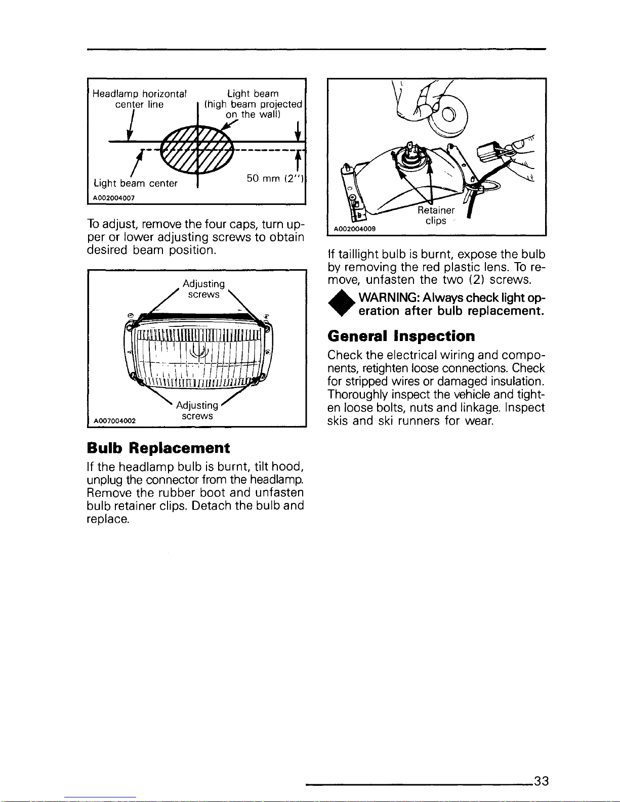
Headlamp horizontal
center line
/-
Light beam center
A002004007
50 mm
(2")
To
adjust, remove the four caps, turn up-
per or lower adjusting screws to obtain
desired beam position.
Bulb Replacement
If the headlamp bulb
is
burnt, tilt hood,
unplug the connector from the
headlamp.
Remove the rubber boot and unfasten
bulb retainer clips. Detach the bulb and
replace.
If taillight bulb
is
burnt, expose the bulb
by removing the
red
plastic lens.
To
re-
move, unfasten the
two
(2) screws .
•
WARNING: Always check light op-
eration
after
bulb replacement.
General Inspection
Check the electrical wiring and
compo-
nents,
retighten loose connections. Check
for stripped wires or damaged insulation.
Thoroughly inspect the vehicle and tight-
en
loose bolts, nuts and linkage. Inspect
skis and ski runners for wear.
---------------------------33
Page 36

STORAGE
__________________
_
It
is
during summer, or when a vehicle
is
not
in
use
for
any length
of
time that
proper storage
is
a necessity. Storage of
the snowmobile during long period of
inactivity consists
of
checking and re-
placing missing, broken or worn parts,
proper lubrication and treatment to in-
sure that parts do not become rusted;
cleaning items such
as
carburetor of oil
mixtures, to prevent gum varnish forma-
tion within the carburetor; and
in
gene-
ral, preparing the vehicle
so
that when
the time comes to use the snowmobile
again it will
be
in
top
condition .
•
WARNING: Only perform such pro-
cedures
as
detailed
in
this manual.
It
is
recommended that dealer assistance
be
periodically obtained
on
other com-
ponents/systems
not
covered
in
this
manual. Unless otherwise specified, en-
gine should
be
turned OFF for
all
lubri-
cation and maintenance procedures.
Track
Inspect the track for wear, cuts, missing
track guides and broken rods. Make any
necessary replacement.
•
WARNING: Do not operate a snow-
mobile with a cut, torn
or
damage
track.
Lift the rear of vehicle until track
is
clear
of the ground then support with a brace
or
trestle.
The snowmobile should
be
sto-
red
in
such a way that the track does not
stay
in
contact with the cement floor or
bare ground.
0
NOTE: The track should
be
rotat-
ed
periodically,
(every
40
days).
Do
not
release
track tension.
,.,.
CAUTION:
To
prevent track dam-
T age, temperature
in
the
storage
area
must
not exceed
38°C
(100°F).
Suspension
Remove any dirt or rust. Grease idler
wheels at grease fittings. (If applicable).
Wipe
off
surplus. Replace worn slider
shoes.
Skis
Wash or brush
all
dirt or rust accumula-
tion from the skis and springs. Grease
the ski legs at the grease fittings.
•
WARNING:
Check
the
condition
of
the
skis, ski runners and leaf
spring. Replace if
weak
or worn more
than half.
A007006006
Controls
Lubricate the steering mechanism. Inspect
all
components for tightness, (spring cou-
pler bolts, steering arm locking bolts, tie
rods,
ball
joints,
etc.)
Tighten if
necessary.
Oil
metal moving joints of the
brake
mech-
anism.
•
WARNING:
Do
not lubricate
the
throttle and/or brake cables and
housings. Avoid getting
oil
on
the brake
pads.
Coat
all
electrical
connections
and
switches
with a greaseless metal protector. If un-
available, use petroleum jelly.
Chaincase
Drain the chaincase and refill to proper
level, using fresh chaincase oil
(P/N
413
8019 00).
To
drain, remove the chain-
case cover.
Drive Pulley
Inspection and cleaning must
be
per-
formed by
an
authorized dealer at the
end of each season.
Engine and Primer Lubrication
Engine internal parts must
be
lubricated
to protect them from possible rust for-
mation during the storage period.
34
________________________
__
Page 37

To
perform the storage procedures (en-
gine
and
primer
valve)
proceed
as
follows:
1.
Lift the
rear
of the vehicle
and
support
it off the ground.
•
WARNING:
Ensure
the track
is
free
of
ails particles which could be
thrown out while it
is
rotating. Keep
hands,
tools, feet and clothing clear of
track.
Ensure
no-one
is
standing
in
close
proximity to the vehicle.
2.
Start the engine and allow it to run
at idle speed until the engine reaches
its operational temperature.
3.
Stop the engine.
4. Disconnect the inlet primer
hose
from
the primer
valve.
Inlet (Oblique
hose
coupling)
~~
~~l__Z~
Outlet (Straight
hose
coupling)
A002002009
5.
Plug
inlet primer hose to prevent gas-
oline from draining.
6.
Using
an
appropriate hose, connect
one end of the hose to the inlet of
the primer valve and place the other
end
in
a Bombardier Snowmobile In-
jection
Oil
container.
7.
Activate
the
primer
in
order
to
fill
it
with
oil.
8.
Restart engine and run at idle.
9.
Using the primer valve, inject oil un-
til the engine dies or until a sufficient
quantity of oil
has
entered the engine
(approximately
25
complete strokes
of
the primer).
10.
The
engine stopped, remove the spark
plug and pour approximately
85
ml
(3 fl. imp.
oz)
of oil into the cylinder.
11.
Crank the engine to allow the crank-
shaft to turn 2 or 3 revolutions.
12. Reinstall the spark plug and the inlet
primer hose .
Do
not run engine during storage pe-
riod.
Fuel
Tank
and
Carburetor
Remove the cap then using a syphon,
remove the gasoline from tank.
•
WARNING: Gasoline
is
flamma-
ble and explosive under certain
conditions. Always manipulate
in
a well
ventilated area.
Do
not smoke or allow
open flames or sparks
in
the vicinity.
Carburetor must
be
dried out completely
to prevent gum formation during the stor-
age period.
Once the fuel tank
is
emptied, remove
the float chamber drain plug from carbu-
retor. Drain carburetor.
A002002010
Reinstall plug.
Check
all
fuel lines, replace if necessary.
Battery (electric
starting
only)
1.
Disconnect the battery cables
and
re-
move the battery retainer
cover.
..r
CAUTION:
Be
careful not to
ground
T positive terminal
with
the chas-
sis.
Always disconnect black negative
cable first.
-------------------------35
Page 38

2.
Remove the battery vent tube from
the vent hole.
3.
Lift
out
the battery.
4. Clean outside surface
of
battery with
solution
of
baking soda and water.
Remove all deposits from posts then
rinse
with
clear tap water.
"W' CAUTION: Do not allow cleaning
T solution
to
enter battery interi-
or since it will destroy
the
electrolyte.
5.
Check electrolyte level. Refill if nec-
essary with distilled
water.
Fully
charge
battery at a maximum
rate
of 2.0
amps.
"W' CAUTION: Prior to charging
the
T battery, always remove it from the
vehicle
to
prevent electrolyte spillage.
•
WARNING:
Gases given off
by
a
battery being charged are highly
explosive. Always charge
in
a well ven-
tilated area. Keep battery away from
cigarettes or open flames. Avoid skin
contact
with
electrolyte.
6.
Coat electrical connections and swit-
ches with a greaseless metal projec-
tor, if unavailable, use petroleum
jelly.
7.
Store unit
in
a cool, dry
place.
0
NOTE:
To
prevent battery from dis-
charging, store it
on
a wooden shelf
away from moisture. A stored battery must
be
recharged at least every
40
days.
Chassis
Clean the vehicle thoroughly, removing
all dirt and grease accumulation.
"W' CAUTION: Plastic alloy compo-
T nents such
as
fuel tank,
wind-
shield, controls, etc., can be cleaned
using
mild detergents
or
isopropyl alco-
hol.
Do not
use
strong
soaps,
degreasing
solvents, abrasive cleaners, paint thin-
ners, etc.
Inspect the hood and repair any damage.
Clean the frame.
Touch
up
all
metal spots where paint has
been scratched off. Spray
all
bare metal
parts with metal protector. Wax the hood
and the painted portion of the frame for
better protection.
0
NOTE: Apply wax on glossy finish
only.
Protect the vehicle with a cov-
er to prevent dust accumulation during
storage.
"W' CAUTION: If for some reason the
T snowmobile has to
be
stored out-
side it
is
necessary
to
cover it
with
an
opaque tarpaulin. This caution will pre-
vent
the
sun rays and
the
grime from
affecting the plastic components and
the
vehicle finish.
General
Inspection
Check the electrical wiring and
compo-
nents, retighten loose connections. Check
for stripped wires or damaged insulation.
Thoroughly inspect the vehicle and tighten
loose bolts, nuts and linkage.
0
NOTE:
Leave
the drive belt
off
the
pulleys for the entire storage pe-
riod.
Suspension
Stopper
Strap
Replace
annually and/or
as
condition dic-
tates. Torque nut to:
Citation LS/LSE: 7
N•m
(62
lbf•inl
Tundra,
Tundra
LT/LTS: 9 N•m
(80 lbf•inl.
36
________________________
___
Page 39

PRE-SEASON
PREPARATION-------------------------
To
simplify
the
pre-season
preparation
we
have
drawn up a small chart.
The
chart
indicates servicing points to
be
performed
by
yourself or your authorized dealer. If
these services
are
performed
as
sugges-
ted, your vehicle will give many hours of
fun and low cost
use.
IMPORTANT:
Observe
all
Warnings and
Cautions mentioned
throughout
this
manual which
are
pertinent
to
the item
being checked. When component con-
ditions seem less than satisfactory, re-
place
with
genuine Bombardier parts or
suitable equivalents.
PRE-SEASON
TO
BE
PERFORMED
BY
DEALER
•
PREPARATION
CHART
TO
BE
PERFORMED
BY
OWNER
0
Change spark
plug*
0
Check chaincase oil level
0
Replace fuel
filter
(located inside fuel tank)
0
Check
track
condition, tension and alignment
0
Lubricate suspension
0
Inspect drive belt and install
0
Check
throttle
cable
for
damage and free operation
0
Check steering alignment and ski runner condition
0
Inspect seals
for
possible cuts or leaks
0
Check electrical
wiring
(broken wire, damaged insulation)
0
Reinstall battery (electric starting model)
0
Inspect condition
of
starting rope
0
Check tightness
of
all bolts,
nuts
and linkage
0
Refill gas
tank
0
Replace injection oil
filter
(not applicable
to
Tundra
LTS)
•
Refill injection oil
tank
(not applicable
to
Tundra
LTS)
0
Inspect brake condition and operation
•
Set engine timing
•
Check pulleys, verify components and clean
•
Adjust
carburetor
•
Adjust
oil injection pump (not applicable
to
Tundra
LTS)
•
Check fan belt condition and adjust tension
•
0
*NOTE: Before installing new spark plug, it
is
suggested to burn the excess
storage oil
by
starting the engine, using the old spark plug.
T CAUTION: Only perform
this
procedure in a well ventilated area.
---------------------------37
Page 40

TROUBLE
SHOOTING---------------------------
0
NOTE:
The possible causes
have
been listed
in
an
order
of
frequency. There-
fore, items should
be
checked out
in
the same order
as
mentioned
in
the trouble
shooting guide.
SYMPTOMS
POSSIBLE
CAUSES
WHAT
TO
DO
Engine turns over but
1.
No
fuel
to
the
engine
Check
the
tank
level.
Check
for
possible
clogging
fails
to
start
or
starts
of
fuel
line,
item
4.
with difficulty
2. Flooded engine
Remove
wet
spark
plug,
turn
ignition
to
OFF
and
crnnk
engine
severn!
times.
Install
clean
dry
spark
plug.
Start
engine
following
usual
starting
pro-
cedure.
If
engine
continues
to
flood,
see
your
dealer.
3. Spark plug/ignition
Check
that
emergency
cut-out
switch
is
at
the
upper
position
IONI
and
the
tether
cut-out
switch
cap
is
snapped
over
the
receptacle.
Check
for
fouled
or
defective
spark
plug.
Dis-
connect
spark
plug
wire,
unscrnw
plug
and
re-
move
from
cylinder
head.
Reconnect
wire
and
ground
exposed
plug
on
engine
cowl,
being
careful
to
hold
away
from
spark
plug
hole.
Follow
engine
starting
procedure
and
check
for
spark.
If
no
sparks
appear,
replace
spark
plug.
If
trou-
ble
persists,
contact
your
dealer.
4.
Clogged fuel line (water or
Remove
and
clean
the
fuel
filter.
Change
filter
dirt)
cartridge
if
necessary.
Check
condition
and
connections
of
fuel
lines.
Check
the
cleanliness
of
fuel
tank.
5. Carburetor
Contact
your
dealer
for
repair.
6.
Too
much
oil
in
fuel
See
the
dealer
for
oil
injection
pump
adjustment.
7.
Engine timing
Engine
timing
may
be
incorrect
or
out
of
ad-
justment.
Contact
your
dealer.
8. Engine compression
Running
with a lean
fuel
mixture
may
produce
excessive
engine
wear
resulting
in
poor
engine
compression.
If
this
occurs,
contact
your
dealer
at
once.
Engine
will
not
turn
1.
Seized engine
In
the
case
of a seized
engine
contact
your
manually
dealer.
38--------------------------
Page 41

SYMPTOMS
POSSIBLE
CAUSES
WHAT
TO
DO
Engine lacks accelera-
1.
Fouled
or
defective
spark
Check
item 3 of
"Engine
turns
over
but
fails
tion
or
power
plug
to
start
or
starts
with
difficulty"
2. Clogged fuel line
(water
or
Check
fuel
line
condition.
!See
item 4 of
"En-
dirt)
gine
turns
over
but
fails
to
start
or
starts
with
difficulty''!.
3.
Carburetors
Contact
your
dealer.
4.
Ignition
First
check
item 3 of
"Engine
turns
over
but
fails
to
start
or
starts
with
difficulty".
If
the
ignition
system
still
seems
faulty,
contact
your
dealer.
5. Engine
If
unable
to
locate
specific
symptoms,
contact
your
dealer.
Engine
continually
1.
Faulty
spark
plug
Check
item 3 of
"Engine
turns
over
but
fails
to
backfires
start
or
starts
with
difficulty':
2. Overheated
Carburetor
set
too
lean,
contact
your
dealer.
3. Engine timing incorrectly set
Contact
your
dealer.
Snowmobile
cannot
1.
Drive
Belt
Check
for
damaged
or
worn
drive
belt.
Replace
reach full speed
if
necessary.
2.
Incorrect
track
adjustment
Check
track
tension
and
alignment.
Readjust
to
specifications.
!See
Maintenance
Section).
3. Engine
Check
item 1 to 5 of
"Engine
lacks
accelera·
tion
or
power::
4. Pulley misaligned
Contact
your
dealer.
---------------------------39
Page 42

TOOLS
As
standard equipment
each
new snow-
mobile
is
supplied with basic tools such
as
screwdriver, wrenches, emergency
starter rope, etc.
Standard Tools
A
~
c=
'
D
E
c
r
I
I i
I
'
u
A.
Screwdriver
B.
Socket
21/26
mm
C.
Socket
10/13
mm
D.
Socket
handle
E.
Fork
wrench
10/13
mm
F.
Starter
rope
G. Suspension key (Tundra models only)
H. Carry-boose adapter (Tundra models only)
I.
Emergency
starter
clip (Citation models only)
A001001038
40
______________________
__
G
H
0
~
@=B
Page 43

SPECIFICATIONS
_______
_
CITATION
LS
CITATION
LSE
TUNDRA
ENGINE
Type
253
No
of
cylinders
1
Bore
72.0
mm
(2.835")
Stroke 61.0
mm
(2.402")
Displacement
248.4
cm3 (15.16 in3)
Compression ratio (effective)
6.25:1
Maximum horsepower R.P.M.*
7000
Carburetor
type
VM
34-319
Carburetor adjustment:
-air
screw
1 turn
-
idle speed
1100 -
1300
R.P.M.
Fan
belt deflection
10
mm
(3/8")
Torque:
- crankcase/cylinder
nuts
M8:
26
N•m
(19
lbf•ft)
- crankcase screws
M6: 9 N•m
(7
lbf•ft)
- magneto ring
nut
85
N•m
(63
lbf•ft)
- fan
nut
60
N•m
(44
lbf•ft)
- crankcase engine support
21
N•m
(15
lbf•ft)
-
nuts
or screws
- electrical starter bolts
N.A.
M5: 3.3
N•m
(29
lbf•ft)
N.A.
CHASSIS
Overall length
242
em
(95.3")
272
em (107.1")
272
em (107.1")
Overall
width
84.5
em
(33.3")
Overall height
111
em
(43.7")
Ski stance (center
to
center)
72.5
em
(28.5")
Ski alignment (toe out) 3
mm
(1/8")
Torque:
- steering arm/ski leg bolt
50
N•m
(37
lbf•ft)
- steering column/handlebar
26
N•m
(19
lbf•ft)
Weight 140.6 kg (310 lb)
150.6 kg
(332
lb)
148.8 kg
(328
lb)
Bearing area
4748
cm2
(736
in2)
4748
cm2
(736
in2)
6600
cm2 (1023
in2)
Ground pressure
2.96
kPa
(.421 lb/in2)
3.17
kPa
(.451 lb/in2)
2.25
kPa
(.321 lb/in2)
*The
maximum horse power
RPM
is applicable
with
engine on
the
vehicle. It may
be
different under certain cir-
cumstances and Bombardier Inc. reserves
the
right
to
modify
it
without
any obligation.
--------------------------41
Page 44

CITATION
LS
CITATION
LSE
TUNDRA
POWER
TRAIN
Track:
-width
38.1 em
(15")
- length
260
em
(102")
260
em
(102")
315 em
(124")
-tension
13
mm (1/2") gap between slider shoe and bottom inside
of
track
-alignment
Equal distance between edge
of
track
guides and slider shoes
Standard gear ratio
15/27
15/27
12/27
Drive belt:
-number
414
3758
00
414
3758
00
414
5234
00
-max.
width
33.3
mm
(1
5/16")
-min.
width
30
mm
(1
3!16")
Chaincase oil
200
ml
(7 oz)
ELECTRICAL
Lighting system (output)
160W
Bulb:
- headlamp
60!60
w
- tail/stop
5/21
w
Fuse:
-
starter
solenoid
N.A.
30A
N.A.
Spark plug
-type
NGK BR9ES
(NO
W24ESR-U)
- gap
0.4
mm
(.016")
Ignition timing:
- timing mark
(B.T.D.C.)
1.88
mm
(.074")
(18°)
- stroboscopic
timing
6000
R.P.M.
FUEL
Gas
type
Regular leaded or unleaded
Fuel
tank
capacity:
- Sl
261
-Imp.
5.7 gal.
-u.s.
6.9
gal.
Lubrication
type
Oil injection system
Oil type:
Bombardier oil injection oil
- Sl
1.51
-Imp.
53
oz
-u.s.
51
oz
BRAKE
Type
Disc self-adjusting
Lining minimum thickness
3
mm
(1/B")
Control lever adjustment 13
mm
(1/2")
minimum distance
from
handlebar grip
when
fully
apply
Bombardier
Inc.
reserves the right to make changes
in
design and specifications and/or to make addi-
tions
to,
or improvements
in
its product
without
imposing any obligation· upon itself to instal/ them on
its
products previously manufactured.
42------------------------
Page 45

TUNDRA
LT
TUNDRA
LTS
ENGINE
Type
253
No
of
cylinders 1
Bore
72.0
mm
(2.835")
Stroke 61.0
mm
(2.402")
Displacement
248.4
cm3
(15.16
in3)
Compression ratio (effective) 6.25:1
Maximum horsepower
R.P.M.*
7000
Carburetor
type
VM
34-319
Carburetor adjustment:
-air
screw 1 turn
- idle speed
1100-
1300
R.P.M.
Fan
belt deflection
10
mm
(3/8")
Torque:
- crankcase/cylinder
nuts
M8:
26
N•m
(19
lbf•ft)
- crankcase screws
M6: 9
N•m
(7
lbf•ft)
- magneto ring nut
85
N•m
(63
lbf•ft)
- fan nut
60
N•m
(44
lbf•ft)
- crankcase engine support
21
N•m
(15
lbf•ft)
nuts or screws
- electrical starter bolts
N.A.
CHASSIS
Overall length
287
em
(113")
Overall width
84.5
em
(33.3")
Overall height
111
em
(43.
7")
Ski stance (center
to
center)
72.5
em
(28.5")
Ski alignment (toe out)
3
mm
(1/8")
Torque:
- steering arm/ski
leg
bolt
50
N•m
(37
lbf•ft)
- steering column/handlebar
26
N•m
(19
lbf•ft)
Weight
162.4 kg
(358
lb)
Bearing area
7581 cm2 (1175 in2)
Ground pressure
2.14
kPa
(.305 lb/in2)
*The
maximum horse power
RPM
is applicable
with
engine on
the
vehicle.
It
may be different under certain cir-
cumstances and Bombardier Inc. reserves
the
right
to
modify
it
without
any obligation.
--------------------------43
Page 46

TUNDRA
LT
TUNDRA
LTS
POWER
TRAIN
Track:
-width
38.1
em
(15")
-length
353
em
(139")
-tension
13
mm
(1/2") gap
between
slider shoe and
bottom
inside
of
track
- alignment Equal distance between edge
of
track
guides and slider shoes
Standard gear ratio
12/27
Drive belt:
-number
414
5234
00
-max.
width
33.3
mm
(1
5/16")
-min.
width
30
mm
(1
3/16")
Chaincase oil
200
ml (7 oz)
ELECTRICAL
Lighting system (output)
160W
Bulb:
- headlamp
60/60
w
-
tail/stop
5/21 w
Fuse:
-
starter
solenoid
N.A.
Spark plug:
-type
NGK BR9ES
(NO
W24ESR-U)
- gap
0.4
mm
(.016")
Ignition timing:
-
timing
mark
(B.T.D.C.)
1.88 mm
(.074")
(18°)
- stroboscopic
timing
6000
R.P.M.
FUEL
Gas
type
Regular leaded or unleaded
Fuel
tank
capacity:
- Sl
26
I
-Imp.
5.7 gal.
-u.s.
6.9 gal.
Lubrication
type
Oil injection system
Premixed fuel/oil
Oil type:
Bombardier injection oil
BLIZZARD oil
-
Sl
1.51
-Imp.
53
oz
-u.s.
51
oz
BRAKE
Type
Disc self-adjusting
Lining
minimum
thickness
3
mm
(118")
Control lever
adjustment
13
mm
(1!2")
minimum
distance
from
handlebar grip
when
fully
apply
Bombardier Inc. reserves the right
to
make changes in design and specifications and/or to make addi-
tions
to,
or
improvements
in
its product
without
imposing any obligation upon itself to install them on
its
products
previously manufactured.
44--------------------------
Page 47
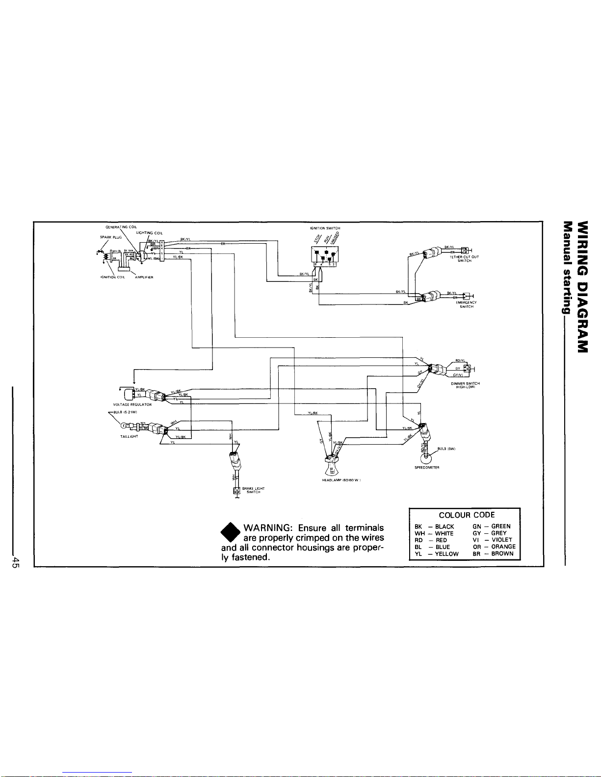
.j:>.
01
GENERA~ING
COIL
LIGHTING
COIL
VOLTAGE REGULATOR
~BI521WI
~
BRAKE LIGHT
SWITCH
.._81
>:J~;
j)
"'/
Q:-/.:;,'"7
HEAOLAMP
(60/60
WI
•
WARNING: Ensure
all
terminals
are properly crimped on the wires
and all connector housings are proper-
ly fastened .
TETHER
CUTOUT
SWITCH
BULB (5WI
EMERGENCY
SWITCH
COLOUR CODE
BK
-BLACK
WH-
WHITE
RD
-RED
BL
-BLUE
YL
-YELLOW
GN-
GREEN
GY-
GREY
VI
-VIOLET
OR-
ORANGE
BR
-BROWN
s::e
m-
:::s
:a
c-
!.2
cnt:)
..
me
::l-
:r
:.>
CQC)
:a
:1>
s:
Page 48

_J:::,.
CJ)
STARTER
FUSE
(30A
l
COLOUR CODE
BK
-BLACK
WH-
WHITE
RD -RED
BL
-BLUE
YL
-YELLOW
GN-
GREEN
GY-
GREY
VI
-VIOLET
OR-
ORANGE
BR
-BROWN
BRAKE LIGHT i
tl
SW,CH'
"
~"
~'UlBI'W'
•
WARNING: Ensure all
terminals
are properly crimped on the wires
and all connector housings are proper-
ly
fastened.
!!!:E
CD_
~:a
..
-
(;"
2
rnQ
....
me
:::l-
3',.
CCC)
:a
,.
I
Page 49

Sl*
METRIC INFORMATION
GUIDE
BASE UNITS
DESCRIPTION
UNIT
length
meter
mass
kilogram
force
Newton
liquid
liter
temperature Celsius
pressure kilo pascal
torque
Newton meter
speed
kilometer per hour
PREFIXES
PREFIX SYMBOL MEANING
kilo k one thousand
centi c
one hundredth of
milli m one thousandth of
CONVERSION FACTORS
TO CONVERT
TOt
lbf•ft
lbf•in
imp.
oz
U.S.
oz
imp. gal.
U.S.
gal.
in
mm
in
em
ft
m
MPH
km/h
in
2
cm
2
in
3
cm
3
imp.
oz
ml
U.S.
oz
ml
imp. gal.
I
U.S.
gal.
I
oz
g
lb
kg
lbf N
lbf•in
N•m
lbf•ft
N•m
PSI
kPa
Fahrenheit Celsius
Celsius
Fahrenheit
SYMBOL
m
kg
N
I
oc
kPa
N•m
km/h
VALUE
1000
0.01
0.001
MULTIPLY
BY
12
0.96
1.2
25.4
2.54
0.3
1.61
6.45
16.39
28.41
29.57
4.55
3.79
28.35
0.45
4.4
0.11
1.36
6.89
(°F-
32) X 5/9
(°C
X
1.8)
+ 32
*The international system of units abbreviates
"SI"
in
all
languages.
tTo obtain the inverse sequence, divide
by
the given factor.
To
convert
"mm"
to
"in",
divide
by
25.4.
----------------------------47
Page 50

NOTES.
____________________
__
Page 51

CHANGE
OF
ADDRESS
OR
OWNERSHIP------------
Any change
in
address or ownership should
be
brought to the attention of the manu-
facturer
by
completing and sending out the card supplied below.
NOTICE
TO
ALL NEW OWNERS: Make sure to receive the warranty registration card
from the previous owner, at the time the ownership
is
transferred. Also enclose
a photocopy of this registration card when informing of a change of ownership.
~----------------------------
CHANGE
OF
ADDRESS
VEHICLE IDENTIFICATION NUMBER I I I I I I I I I I I
OLD ADDRESS:
NAME
NO
STREET
APT.
CITY
STATE/PROVINCE ZIP/POSTAL CODE
NEW ADDRESS:
NAME
NO
STREET
APT
Q.._
CITY STATE/PROVINCE ZIP/POSTAL CODE
~----------------------------
CHANGE
OF
OWNERSHIP
VEHICLE IDENTIFICATION NUMBER I I I I I I I I I I I
The ownership of this vehicle
is
transferred
FROM:
NAME
NO STREET
APT.
CITY
STATE/PROVINCE
. ZIP/POSTAL CODE
TO:
NAME
NO
STREET
APT
CITY
STATE/PROVINCE
ZIP/POSTAL CODE
Page 52

------------------------------1
BOMBARDIER
INC.
ATT.:
WARRANTY DEPARTMENT
VALCOURT, QUEBEC
CANADA,
JOE
2LO
I
I
I
I
I
I
I
I
I
I
I
I
I
I
I
I
I
I
I
I
-------------------------------1
BOMBARDIER
INC.
ATT.:
WARRANTY DEPARTMENT
VALCOURT, QUEBEC
CANADA,
JOE
2LO
I
I
I
I
I
I
I
I
I
I
I
I
I
I
I
I
I
 Loading...