

Page 1

Page 2

Particularly important information in this Operator’s Guide is designated by the
following:
The Safety Alert Symbol means ATTENTION!
Identifies an instruction which if not followed, may cause
WARNING
injuries including the possibility of death.
CAUTION: Denotes an instruction which if not followed, may damage the
ATV and/or components.
WARNING
YOUR ATV CAN BE HAZARDOUS TO OPERATE. A collision or rollover can
occur quickly, even during routine maneuvers such as turning and driving
on hills or over obstacles, if you fail to take proper precautions.
For your safety, understand and follow all the warnings contained in the
Operator’s Guide, the Safety Handbook and the labels on your vehicle. Fail-
ure to follow these warnings can result in SEVERE INJURY OR DEATH.
Keep this Operator’s Guide and the Safety Handbook with the vehicle at all
times.
In USA, products are distributed by Bombardier Motor Corporation of America. In
Canada, products are distributed by Bombardier Inc.
The following are trademarks of Bombardier Inc. or its subsidiaries:
BOMBARDIER
ROTAX
†
Simple Green is a registered trademark of Sunshine Markers Inc.
®
®
Print ed in Cana da (vmo 2002 _004a.fm AP)
®
Trademarks of Bombardier Inc. or its subsidiaries.
©
2001 Bombardier Inc. All rights reserved.
Page 3

FOREWORD
Congratulations on your purchase of a
new Bombardier all-terrain vehicle
(ATV). It is backed by the Bombardier
warranty and a network of authorized
Bombardier ATV dealers ready to provide the parts, service or accessories
you may require.
Your dealer is committed to your satisfaction. He has taken training to perform the initial set-up and inspection of
your vehicle as well as completed the
final adjustment before you took possession. At delivery, your dealer would
have explained the vehicle for the operation, maintenance and safety features.
We trust you have taken full advantage
of this! If you need more complete servicing information, please ask your
dealer about the proper model-year
ATV Shop Manual.
At delivery, you were also informed of
the warranty coverage and completed
the Warranty Registration Form which
is to be sent to us for processing. In
the near future you should be receiving a warranty card which will confirm
our receipt of the registration as well
as be used for warranty or recall purposes.
You are invited to contact our customer assistance center should you experience problems which cannot be resolved by an authorized Bombardier
ATV dealer.
The information and components/
system descriptions contained in this
document are correct at the time of
publication. Bombardier Inc. however,
maintains a policy of continuous improvement of its products without imposing upon itself any obligation to install them on products previously
manufactured. Due to late changes, it
may have some differences between
the manufactured product and the descriptions and/or specifications in this
guide. Bombardier Inc. reserves the
right at any time to discontinue or
change specifications, designs, features, models or equipment without
incurring any obligation upon itself.
The illustrations in this document show
the typical construction of the different
assemblies and may not reproduce the
full detail or exact shape of the parts.
However, they represent parts that
have the same or similar function.
Specifications are given in the SI metric
system with the SAE U.S. equivalent in
parenthesis. Where precise accuracy is
not required, some conversions are
rounded off for easier use.
We recommend genuine Bombardier
products for replacement parts and ac-
cessories. They’ve been especially designed for your vehicle and manufactured to meet Bombardier’s demanding
standards.
It is understood that this guide may be
translated into another language. In
the event of any discrepancy, the English version shall prevail.
A Shop Manual can be obtained for
complete service, maintenance and
more repair information.
1
Page 4

TABLE OF CONTENTS
NOTICE....................................................................................... 4
SPECIAL SAFETY MESSAGES .................................................... 5
OPERATION WARNINGS ............................................................ 7
BOMBARDIER LIMITED WARRANTY NORTH AMERICA:
2002 BOMBARDIER
BOMBARDIER LIMITED WARRANTY INTERNATIONAL:
2002 BOMBARDIER
FREQUENTLY ASKED QUESTIONS ............................................. 40
EMISSION REQUIREMENTS........................................................ 41
LOCATION OF THE IMPORTANT LABELS ................................... 42
HOW TO IDENTIFY YOUR ATV ................................................... 45
Engine and Vehicle Identification Number Location .................................... 45
CONTROLS/INSTRUMENTS/EQUIPMENTS.................................. 46
1) Throttle Lever ........................................................................................ 47
2) Front Brake Lever.................................................................................. 47
3) Rear Brake Lever................................................................................... 47
4) Brake Lever Lock .................................................................................. 48
5) Transmission Lever ............................................................................... 48
6) Headlight Switch ................................................................................... 49
7) Engine Stop Switch ............................................................................... 50
8) Start Button ........................................................................................... 50
9) Indicator Lights Cluster ......................................................................... 50
10) Speedometer ........................................................................................ 51
11) Ignition Switch ...................................................................................... 52
12) Choke Knob Lever................................................................................. 52
13) Fuel Tank Cap........................................................................................ 52
14) Fuel Gauge ............................................................................................ 53
15) Fuel Valve.............................................................................................. 53
16) Rear Brake Pedal................................................................................... 53
17) Rewind Starter Handle (if so equipped) ................................................ 54
18) Footpeg ................................................................................................. 54
19) Storage Compartment........................................................................... 54
20) Seat Latch ............................................................................................. 55
21) Front/Rear Cargo Racks ............................................................................. 55
22) Air Duct ................................................................................................. 55
23) Trailer Hitch ........................................................................................... 56
24) Radiator Cap .......................................................................................... 56
25) 12-Volt Power Outlet............................................................................. 56
26) Fuses..................................................................................................... 57
Winch (if so equipped) ................................................................................. 57
Winch Control Switch (if so equipped)......................................................... 57
Fairlead (if so equipped) ............................................................................... 57
®
ATV........................................................... 34
®
ATV........................................................... 37
2
Page 5

LIQUIDS...................................................................................... 58
Fuel .............................................................................................................. 58
Engine/Transmission Oil.............................................................................. 58
Engine Coolant............................................................................................. 60
Brake Fluid ................................................................................................... 61
Battery Electrolyte ....................................................................................... 62
BREAK-IN PERIOD ...................................................................... 64
Engine.......................................................................................................... 64
Belt .............................................................................................................. 64
10-Hour Inspection ...................................................................................... 64
PRE-OPERATION CHECK ............................................................ 65
OPERATING INSTRUCTIONS ...................................................... 66
General ........................................................................................................ 66
Initial Cold Starting....................................................................................... 66
Warm Engine Starting.................................................................................. 67
Emergency Manual Starting (if so equipped)............................................... 67
Stopping the Engine .................................................................................... 67
Shifting the Transmission ............................................................................ 67
SPECIAL PROCEDURES .............................................................. 68
Flooded Engine............................................................................................ 68
Engine Overheat .......................................................................................... 68
Post-Operation Care .................................................................................... 68
Flipped Over ................................................................................................ 69
ATV Immersion ............................................................................................ 69
Limp Home Mode........................................................................................ 69
Storage and Preseason Preparation............................................................. 69
MAINTENANCE CHART .............................................................. 70
MAINTENANCE .......................................................................... 72
Engine/Transmission.................................................................................... 72
Air Intake System ........................................................................................ 75
Electrical ...................................................................................................... 76
Drive Train.................................................................................................... 79
Steering/Control Systems............................................................................ 81
Suspension .................................................................................................. 82
Brake............................................................................................................ 83
Body/Frame ................................................................................................. 84
CARGO AND TRANSPORTATION................................................ 85
Cargo ........................................................................................................... 85
Transportation.............................................................................................. 86
TROUBLESHOOTING................................................................... 87
SPECIFICATIONS ........................................................................ 90
SI METRIC INFORMATION GUIDE ............................................... 94
CHANGE OF ADDRESS ............................................................... 95
3
Page 6
NOTICE
The Operator’s Guide and Safety Hand-
book have been prepared to acquaint
the owner/operator of a new vehicle
with the various vehicle controls, maintenance and safe operating instructions. They are indispensable for the
proper use of the product.
This Operator’s Guide uses the follow-
ing symbols.
WARNING
Identifies an instruction which, if
not followed, could cause serious
personal injuries including the
possibility of death.
CAUTION: Denotes an instruction
which, if not followed, could severely damage vehicle components.
NOTE: Indicates supplementary infor-
mation needed to fully complete an instruction.
Although the mere reading of such information does not eliminate the hazard, the understanding and application
of the information will promote the
correct use of the all-terrain vehicle
(ATV).
To fully appreciate the pleasures, enjoyment and excitement of using an
ATV, there are some basic rules that
MUST be observed and followed by
any four-wheeler.
4
Page 7

SPECIAL SAFETY MESSAGES
AN ATV IS NOT A TOY AND CAN BE
HAZARDOUS TO OPERATE.
An ATV handles differently from other
vehicles including motorcycles and
cars. A collision or rollover can occur
quickly, even during routine maneuvers such as turning and driving on hills
or over obstacles, if you fail to take
proper precautions.
SEVERE INJURY OR DEATH can result if you do not follow these instructions:
Read the Operator’s Guide, the Safe-
ty Handbook and all labels carefully
and follow the operating procedures described.
Never operate an ATV without proper
instruction. Take a training course.
Beginners should receive training
from a certified instructor. Contact an
authorized ATV dealer to find out
about the training courses nearest
you or call the Specialty Vehicle Institute of America (SVIA) at 1-800-8872887 or in Canada, the Canada Safety
Council (CSC) at 1-613-739-1535 ext.
227.
Always follow this age recommen-
dation: A child under 16 years old
should never operate this ATV.
Never carry a passenger on an ATV.
Never operate an ATV on any paved
surfaces, including sidewalks, driveways, parking lots and streets.
Never operate an ATV on any public
street, road or highway, even a dirt
or gravel one.
Never operate an ATV without wear-
ing an approved helmet that fits
properly. You should also wear eye
protection (goggles or face shield),
gloves, boots, long sleeved shirt or
jacket, and long pants.
Never consume alcohol or drugs be-
fore or while operating this ATV.
Never operate at excessive speeds.
Always go at a speed that is proper
for the terrain, visibility, and operating conditions, and your experience.
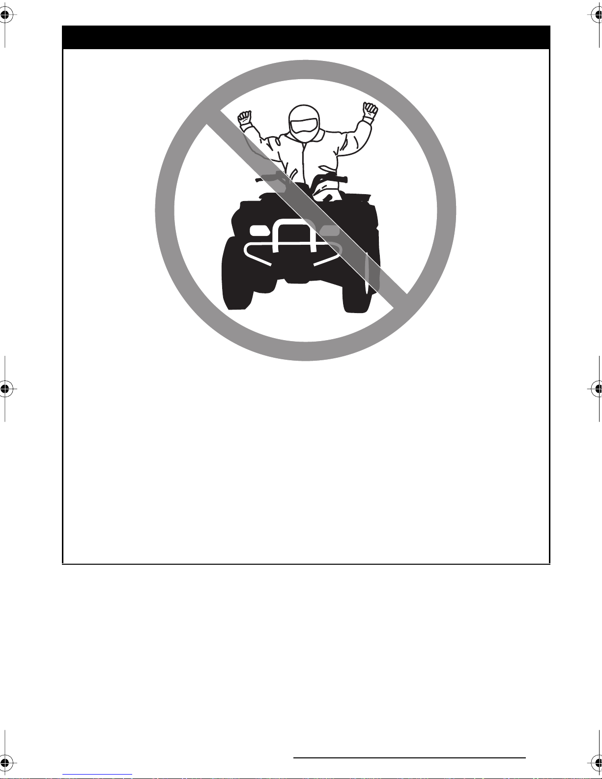
Never attempt wheelies, jumps, or
other stunts.
Always inspect your ATV each time
you use it to make sure it is in safe
operating condition. Always follow
the inspection and maintenance procedures and schedules described in
the Operator’s Guide and the Safety
Handbook.
Always keep both hands on the han-
dlebars and both feet on the footpegs of the ATV during operation.
Always go slowly and be extra care-
ful when operating on unfamiliar
terrain. Always be alert to changing
terrain conditions when operating
the ATV.
Never operate on excessively rough,
slippery or loose terrain until you
have learned and practiced the skills
necessary to control the ATV on
such terrain. Always be especially
cautious on these kinds of terrain.
Always follow proper procedures
for turning as described in the Op-
erator’s Guide and the Safety Hand-
book. Practice turning at low speeds
before attempting to turn at faster
speeds. Do not turn at excessive
speed.
Never operate the ATV on hills too
steep for the ATV or for your abilities. Practice on smaller hills before
attempting larger hills.
5
Page 8

Always follow proper procedures
for climbing hills as described in the
Operator’s Guide and the Safety
Handbook. Check the terrain care-
fully before you start up any hill.
Never climb hills with excessively
slippery or loose surfaces. Shift
your weight forward. Never open
the throttle suddenly or make sudden gear changes. Never go over
the top of any hill at high speed.
Always follow proper procedures
for going down hills and for braking
on hills as described in the Opera-
tor’s Guide and the Safety Hand-
book. Check the terrain carefully be-
fore you start down any hill. Shift
your weight backward. Never go
down a hill at high speed. Avoid going down a hill at an angle that would
cause the vehicle to lean sharply to
one side. Go straight down the hill
where possible.
Always follow proper procedures
for crossing the side of a hill as described in the Operator’s Guide and
the Safety Handbook. Avoid hills
with excessively slippery or loose
surfaces. Shift your weight to the
uphill side of the ATV. Never attempt
to turn the ATV around on any hill until you have mastered the turning
technique described in the Opera-
tor’s Guide and the Safety Hand-
book on level ground. Avoid cross-
ing the side of a steep hill if possible.
Always check for obstacles before
operating in a new area. Never attempt to operate over large obstacles, such as large rocks or fallen
trees. Always follow proper procedures when operating over obstacles as described in the Operator’s
Guide and the Safety Handbook.
Always be careful when skidding or
sliding. Learn to safely control skidding or sliding by practicing at low
speeds and on level, smooth terrain. On extremely slippery surfaces, such as ice, go slowly and be
very cautious in order to reduce the
chance of skidding out of control.
Never operate an ATV in fast flow-
ing water or in water deeper than
that specified in the Operator’s
Guide and the Safety Handbook.
Remember that wet brakes may
have reduced stopping ability. Test
your brakes after leaving water. If
necessary, apply them several times
to let friction dry out the pads.
Always be sure there are no obsta-
cles or people behind you when you
operate in reverse. When it is safe
to proceed in reverse, go slowly.
Always use the size and type tires
specified in the Operator’s Guide.
Always maintain proper tire pressure as described in this guide.
Never modify an ATV through improp-
er installation or use of accessories.
Always use proper procedures if
you stall or roll backwards when
climbing a hill. To avoid stalling, use
proper gear and maintain a steady
speed when climbing a hill. If you
stall or roll backwards, follow the
special procedure for braking described in the Operator’s Guide and
the Safety Handbook. Dismount on
the uphill side or to a side if pointed
straight uphill. Turn the ATV around
and remount, following the procedure described in the Operator’s
Guide and the Safety Handbook.
6
Never exceed the stated load limits
for an ATV. Cargo should be properly
distributed and securely attached.
Reduce speed and follow instructions in the Operator’s Guide and
the Safety Handbook for carrying
cargo or pulling a trailer. Allow greater distance for braking.
FOR MORE INFORMATION ABOUT
ATV SAFETY, call the Specialty Ve-
hicle Institute of America (SVIA) at
1-800-887-2887 or in Canada, the
Canada Safety Council (CSC) at 1613-739-1535 ext. 227.
Page 9
OPERATION WARNINGS
While reading this Operator’s Guide, remember that:
WARNING
Indicates a potential hazard that could result in serious injury or death.
The following warnings and their format have been requested by the United
States Consumer Product Safety Commission and are required to be in the Op-
erator’s Guide and Safety Handbook for all ATV’s.
NOTE: The following illustrations are general representations only. Your model
may differ.
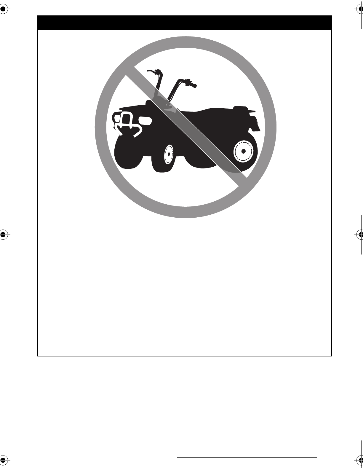
WARNING
V00A0AQ
POTENTIAL HAZARD
Operating this ATV without proper instruction.
WHAT CAN HAPPEN
The risk of an accident is greatly increased if the operator does not know
how to operate the ATV properly in different situations and on different
types of terrain.
HOW TO AVOID THE HAZARD
Beginning and inexperienced operators should complete the certified
training course offered by Bombardier Inc. They should then regularly
practice the skills learned in the course and the operating techniques described in the Operator’s Guide and the Safety Handbook.
For more information about the training course, contact an authorized
ATV dealer or call Bombardier Inc. at 1-819-566-3366.
7
Page 10

WARNING
V00A01Q
POTENTIAL HAZARD
Failure to follow the age recommendations for this ATV.
WHAT CAN HAPPEN
Use by children of ATVs that are not recommended for their age can lead
to severe injury or death of the child.
Even though a child may be within the age group for which an ATV is
recommended, he or she may not have the skills, abilities, or judgment
needed to operate the ATV safely and may be involved in a serious accident.
HOW TO AVOID THE HAZARD
No one under 16 should operate a Bombardier ATV.
8
Page 11

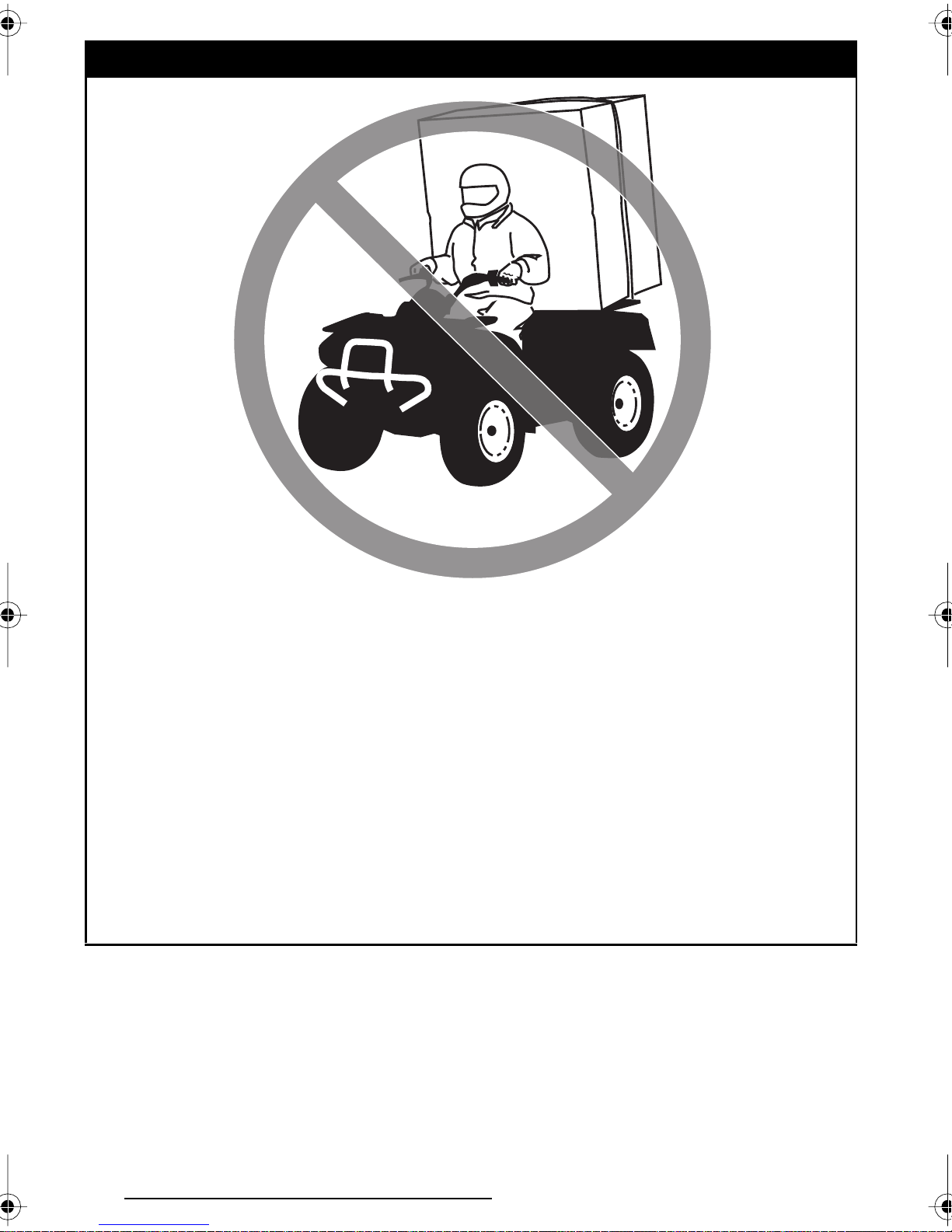
WARNING
V00A02Q
POTENTIAL HAZARD
Carrying a passenger on this ATV or in the rear cargo box.
WHAT CAN HAPPEN
Greatly reduces your ability to balance and control this ATV.
Could cause an accident, resulting in harm to you and/or your passenger.
HOW TO AVOID THE HAZARD
Never carry a passenger. The long seat is to allow the operator to shift
position as needed during operation. The rear cargo box is used to transport material only. They are not for carrying passengers.
9
Page 12

WARNING
V00A03Q
POTENTIAL HAZARD
Operating this ATV on paved surfaces.
WHAT CAN HAPPEN
The ATV’s tires are designed for off-road use only, not for use on pave-
ment. Paved surfaces may seriously affect handling and control of the
ATV, and may cause the vehicle to go out of control.
HOW TO AVOID THE HAZARD
Never operate the ATV on any paved surfaces, including sidewalks, driveways, parking lots and streets.
10
Page 13

WARNING
V00A04Q
POTENTIAL HAZARD
Operating this ATV on public streets, roads or highways.
WHAT CAN HAPPEN
You can collide with another vehicle.
HOW TO AVOID THE HAZARD
Never operate this ATV on any public street, road or highway, even a dirt
or gravel one. In many states it is illegal to operate ATVs on public streets,
roads and highways.
11
Page 14

WARNING
V00A06Q
POTENTIAL HAZARD
Operating this ATV without wearing an approved motorcycle helmet, eye
protection and protective clothing.
WHAT CAN HAPPEN
Operating without an approved motorcycle helmet increases your chances of a severe head injury or death in the event of an accident.
Operating without eye protection can result in an accident and increases
your chances of a severe injury in the event of an accident.
Operating without protective clothing increases your chances of severe
injury in the event of an accident.
HOW TO AVOID THE HAZARD
Always wear an approved motorcycle helmet that fits properly. You
should also wear:
– eye protection (goggles or face shield)
– gloves
– boots
– Iong sleeved shirt or jacket
– Iong pants.
12
Page 15

WARNING
V00A07Q
POTENTIAL HAZARD
Operating this ATV after consuming alcohol or drugs.
WHAT CAN HAPPEN
Could seriously affect your judgment.
Could cause you to react more slowly.
Could affect your balance and perception.
Could result in an accident.
HOW TO AVOID THE HAZARD
Never consume alcohol or drugs before or while driving this ATV.
13
Page 16
WARNING
V00A08Q
POTENTIAL HAZARD
Operating this ATV at excessive speeds.
WHAT CAN HAPPEN
Increases your chances of losing control of the ATV, which can result in
an accident.
HOW TO AVOID THE HAZARD
Always travel at a speed which is proper for the terrain, visibility and operating conditions, and your experience.
14
Page 17
WARNING
V00A09Q
POTENTIAL HAZARD
Attempting wheelies, jumps and other stunts.
WHAT CAN HAPPEN
Increases the chance of an accident, including an overturn.
HOW TO AVOID THE HAZARD
Never attempt stunts, such as wheelies or jumps. Don’t try to show off.
15
Page 18

WARNING
POTENTIAL HAZARD
Failure to inspect the ATV before operating.
Failure to properly maintain the ATV.
WHAT CAN HAPPEN
Increases the possibility of an accident or equipment damage.
HOW TO AVOID THE HAZARD
Always inspect your ATV each time you use it to make sure the ATV is in
safe operating condition.
Always make sure that the rear cargo box is properly latched before operating.
Always follow the inspection and maintenance procedures and schedules
described in the Operator’s Guide and the Safety Handbook.
16
Page 19
WARNING
V00A0BQ
POTENTIAL HAZARD
Removing hands from handlebars or feet from footpegs during operation.
WHAT CAN HAPPEN
Removing even one hand or foot can reduce your ability to control the
ATV or could cause you to lose your balance and fall off the ATV. If you
remove a foot from the footpegs, your foot or leg may come into contact
with the rear wheels, which could injure you or cause an accident.
HOW TO AVOID THE HAZARD
Always keep both hands on the handlebars and both feet on the footpegs
of your ATV during operation.
17
Page 20
WARNING
V00A0CQ
POTENTIAL HAZARD
Failure to use extra care when operating this ATV on unfamiliar terrain.
WHAT CAN HAPPEN
You can come upon hidden rocks, bumps, or holes, without enough time
to react.
Could result in the ATV overturning or going out of control.
HOW TO AVOID THE HAZARD
Go slowly and be extra careful when operating on unfamiliar terrain.
Always be alert to changing terrain conditions when operating the ATV.
18
Page 21
V00A0DQ
POTENTIAL HAZARD
WARNING
Failure to use extra care when operating on excessively rough, slippery
or loose terrain.
WHAT CAN HAPPEN
Could cause loss of traction or vehicle control, which could result in an
accident, including an overturn.
HOW TO AVOID THE HAZARD
Do not operate on excessively rough, slippery or loose terrain until you
have learned and practiced the skills necessary to control the ATV on such
terrain.
Always be especially cautious on these kinds of terrain.
19
Page 22
WARNING
V00A0EQ
POTENTIAL HAZARD
Turning improperly.
WHAT CAN HAPPEN
ATV could go out of control, causing a collision or overturn.
HOW TO AVOID THE HAZARD
Always follow proper procedures for turning as described in the Operator’s Guide and the Safety Handbook. Practice turning at low speeds be-
fore attempting to turn at faster speeds.
Do not turn at excessive speed.
20
Page 23
WARNING
V00A0QQ
POTENTIAL HAZARD
Operating on excessively steep hills.
WHAT CAN HAPPEN
The vehicle can overturn more easily on extremely steep hills than on
level surfaces or small hills.
HOW TO AVOID THE HAZARD
Never operate the ATV on hills too steep for the ATV or for your abilities.
Practice on smaller hills before attempting larger hills.
21
Page 24
WARNING
V00A0FQ
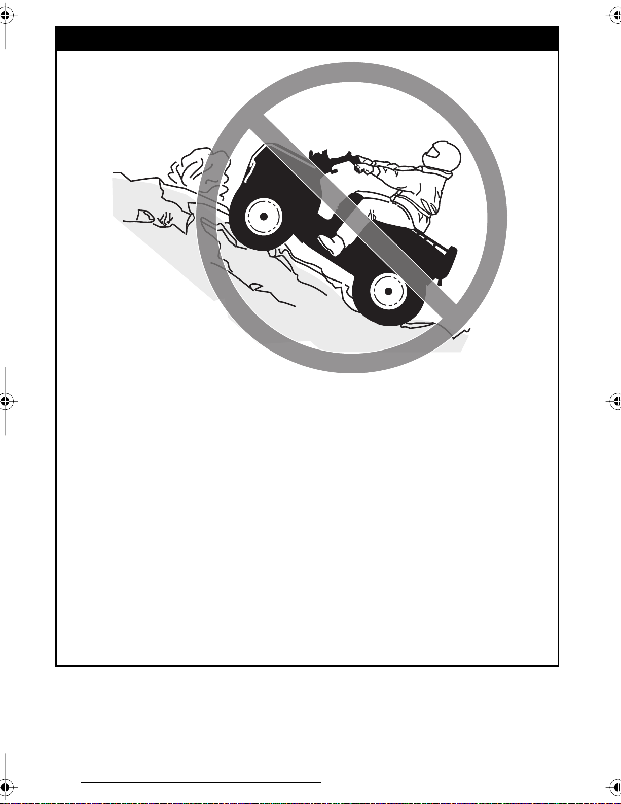
POTENTIAL HAZARD
Climbing hills improperly.
WHAT CAN HAPPEN
Could cause loss of control or cause ATV to overturn.
HOW TO AVOID THE HAZARD
Always follow proper procedures for climbing hills as described in the
Operator’s Guide and the Safety Handbook.
Always check the terrain carefully before you start up any hill.
Never climb hills with excessively slippery or loose surfaces.
Shift your weight forward.
Never open the throttle suddenly or make sudden gear changes. The ATV
could flip over backwards.
Never go over the top of any hill at high speed. An obstacle, a sharp drop,
or another vehicle or person could be on the other side of the hill.
22
Page 25
WARNING
V00A0GQ
POTENTIAL HAZARD
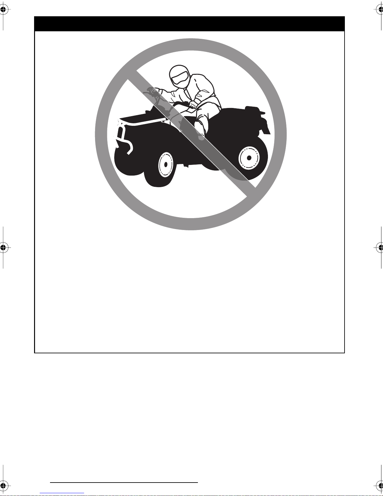
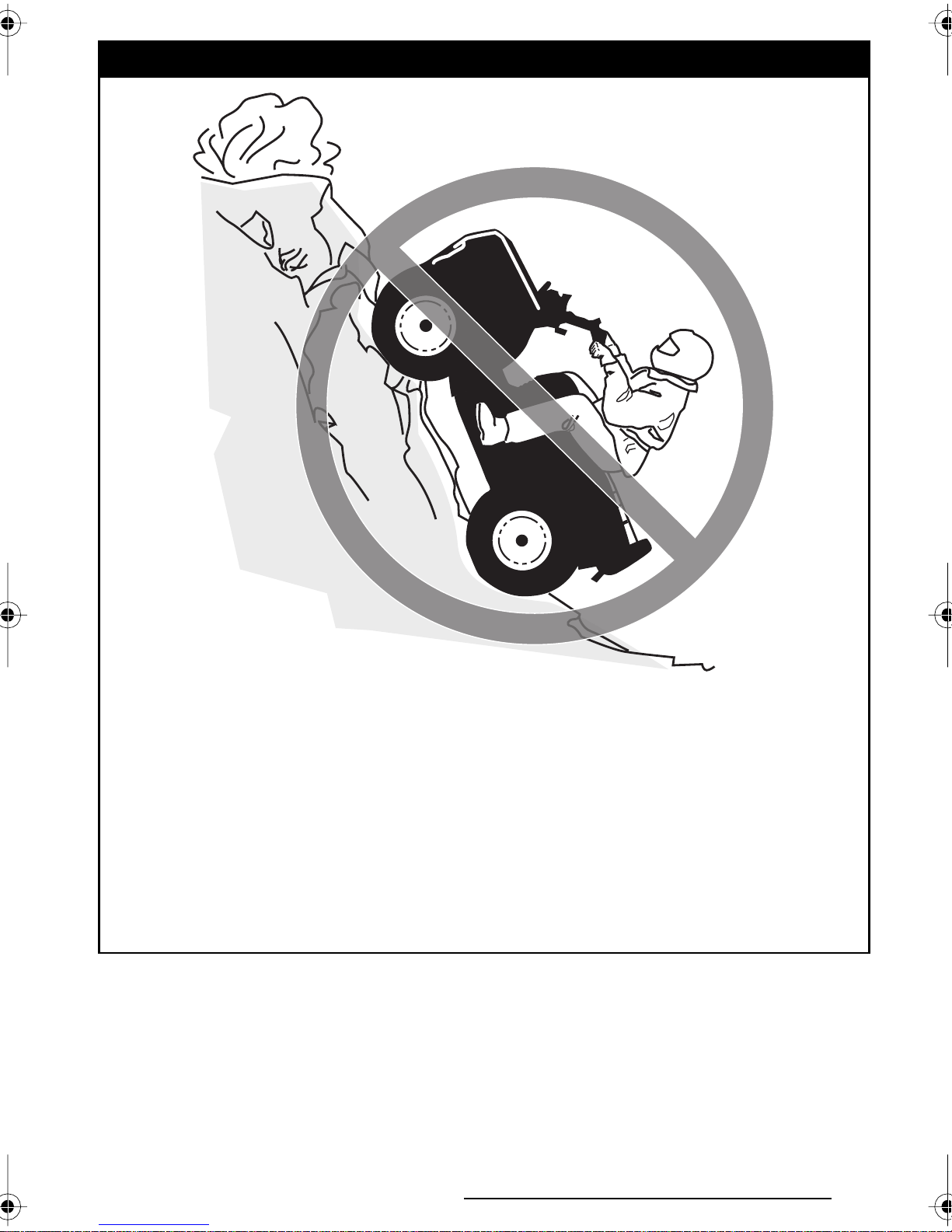
Going down a hill improperly.
WHAT CAN HAPPEN
Could cause loss of control or cause ATV to overturn.
HOW TO AVOID THE HAZARD
Always follow proper procedures for going down hills as described in the
Operator’s Guide and the Safety Handbook.
NOTE: A special technique is required when braking as you go down a hill.
Always check the terrain carefully before you start down any hill.
Shift your weight backward.
Never go down a hill at high speed.
Avoid going down a hill at an angle which would cause the vehicle to lean
sharply to one side. Go straight down the hill where possible.
23
Page 26

WARNING
V00A0HQ
POTENTIAL HAZARD
Improperly crossing hills or turning on hills.
WHAT CAN HAPPEN
Could cause loss of control or cause ATV to overturn.
HOW TO AVOID THE HAZARD
Never attempt to turn the ATV around on any hill until you have mastered
the turning technique as described in the Operator’s Guide and the Safety
Handbook on level ground. Be very careful when turning on any hill.
Avoid crossing the side of a steep hill if possible.
When crossing the side of a hill:
Always follow proper procedures as described in the Operator’s Guide
and the Safety Handbook.
Avoid hills with excessively slippery or loose surfaces.
Shift your weight to the uphill side of the ATV.
24
Page 27

V00A0IQ
POTENTIAL HAZARD
WARNING
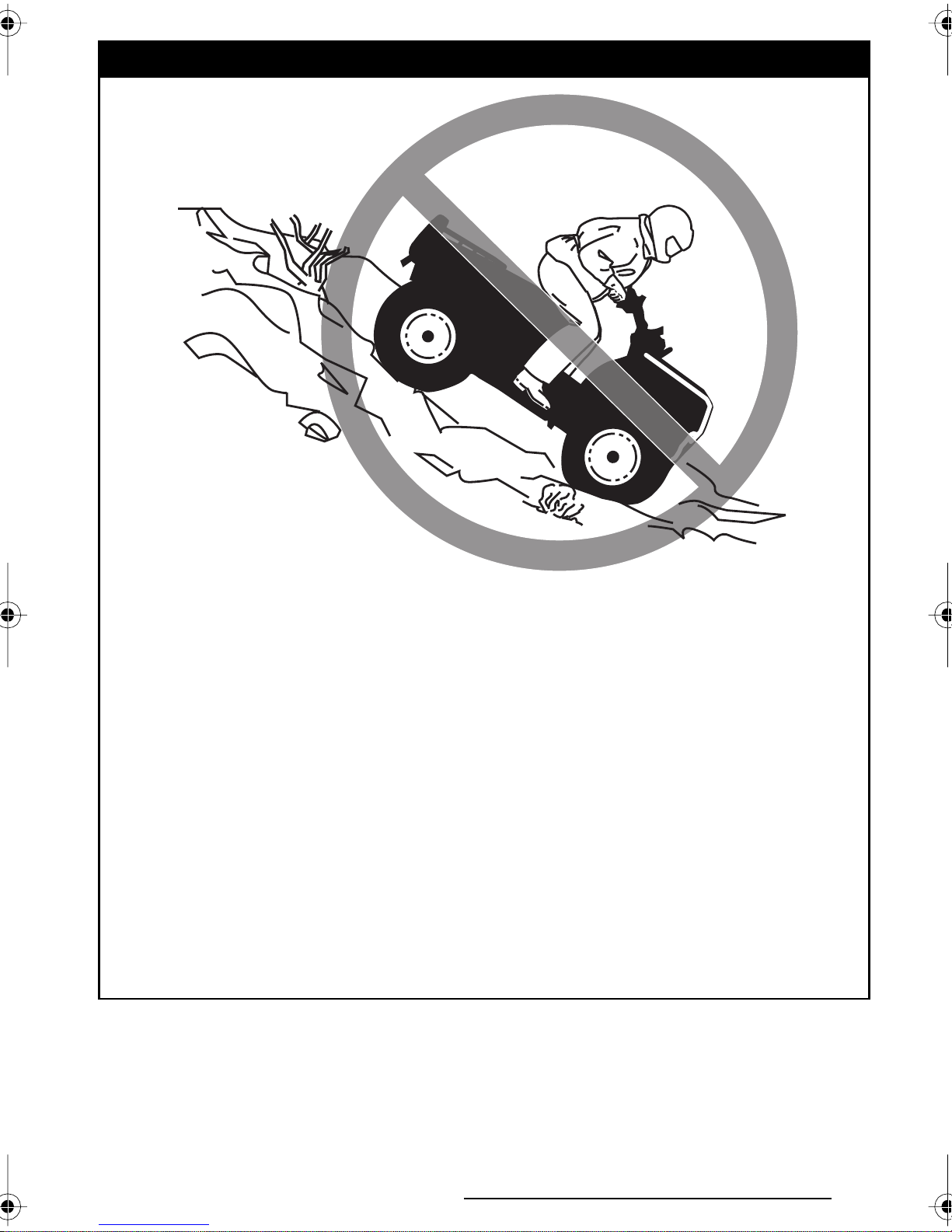
Stalling, rolling backwards or improperly dismounting while climbing a
hill.
WHAT CAN HAPPEN
Could result in ATV overturning.
HOW TO AVOID THE HAZARD
Use proper gear and maintain steady speed when climbing a hill.
If you lose all forward speed:
Keep weight uphill.
Apply the brakes.
Lock parking brake after you are stopped.
If you begin rolling backwards:
Keep weight uphill.
Never apply the rear brake while rolling backwards.
Apply the front brake gradually.
When fully stopped, apply rear brake as well and lock parking brake.
Dismount on uphill side, or to a side if pointed straight uphill.
Turn the ATV around and remount, following the procedure described in
the Operator’s Guide and the Safety Handbook.
25
Page 28

WARNING
V00A0JQ
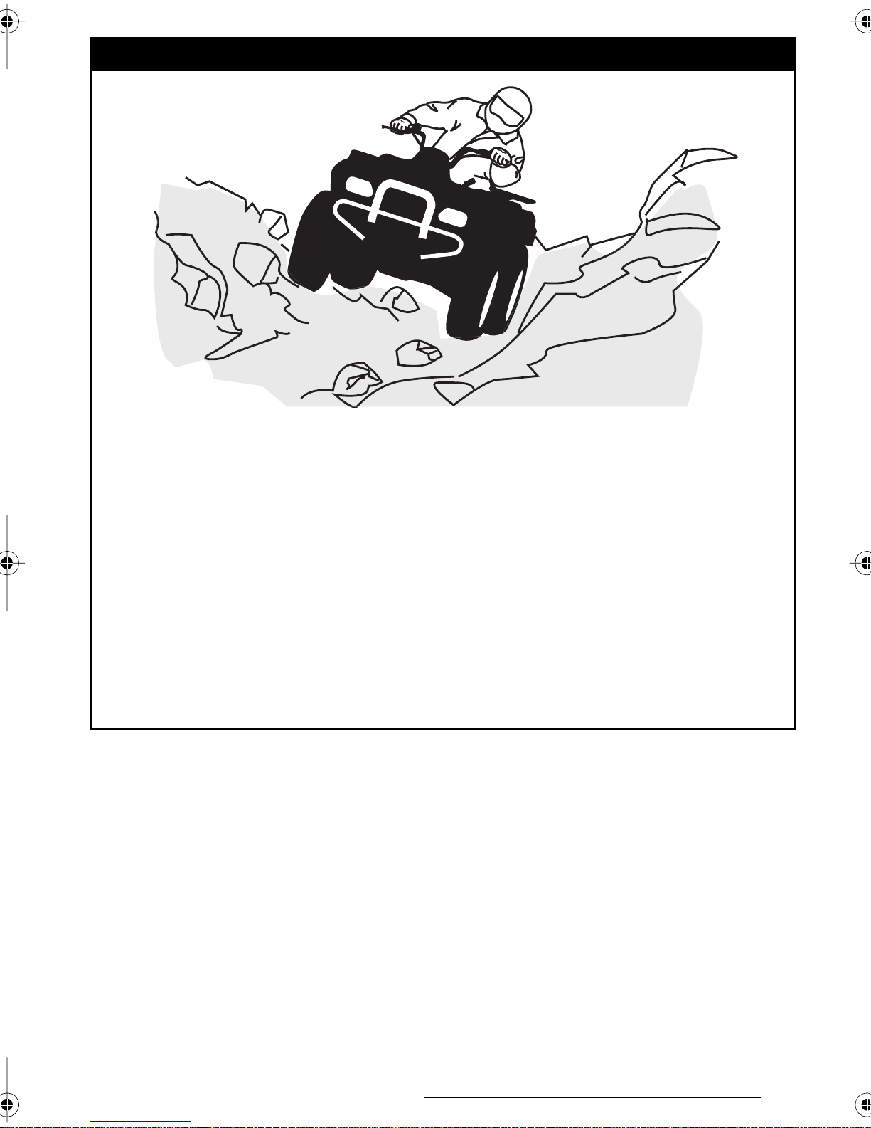
POTENTIAL HAZARD
Improperly operating over obstacles.
WHAT CAN HAPPEN
Could cause loss of control or a collision. Could cause the ATV to overturn.
HOW TO AVOID THE HAZARD
Before operating in a new area, check for obstacles.
Never attempt to ride over large obstacles, such as large rocks or fallen
trees.
When you go over obstacles, always follow proper procedures as de-
scribed in the Operator’s Guide and the Safety Handbook.
26
Page 29

WARNING
V00A0KQ
POTENTIAL HAZARD
Skidding or sliding improperly.
WHAT CAN HAPPEN
You may lose control of this ATV.
You may also regain traction unexpectedly, which may cause the ATV to
overturn.
HOW TO AVOID THE HAZARD
Learn to safely control skidding or sliding by practicing at low speeds and
on level, smooth terrain.
On extremely slippery surfaces, such as ice, go slowly and be very cautious in order to reduce the chance of skidding or sliding out of control.
27
Page 30

WARNING
V00A0LQ
POTENTIAL HAZARD
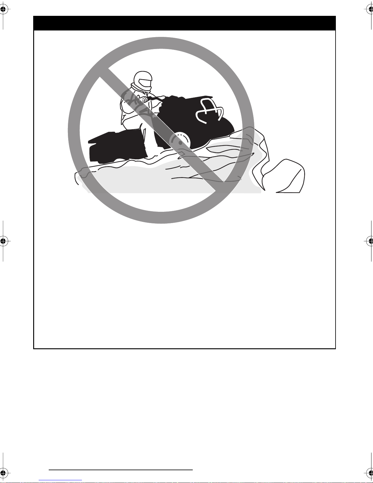
Operating this ATV through deep or fast flowing water.
WHAT CAN HAPPEN
Tires may float, causing loss of traction and loss of control, which could
lead to an accident.
HOW TO AVOID THE HAZARD
Never operate this ATV in fast flowing water or in water deeper than that
specified in the Operator’s Guide and the Safety Handbook.
Remember that wet brakes may have reduced stopping ability. Test your
brakes after leaving water. If necessary, apply them several times to let
friction dry out the pads.
28
Page 31

WARNING
V00A0MQ
POTENTIAL HAZARD
Improperly operating in reverse.
WHAT CAN HAPPEN
You could hit an obstacle or person behind you, resulting in serious injury.
HOW TO AVOID THE HAZARD
When you select reverse gear, make sure there are no obstacles or people
behind you. When it is safe to proceed, go slowly.
29
Page 32
WARNING
V00A0OQ
POTENTIAL HAZARD
Operating this ATV with improper tires, or with improper or uneven tire
pressure.
WHAT CAN HAPPEN
Use of improper tires on this ATV, or operation of this ATV with improper
or uneven tire pressure, may cause loss of control, and increases the risk
of an accident.
HOW TO AVOID THE HAZARD
Always use the size and type, tires specified in the Operator’s Guide for
this vehicle.
Always maintain proper tire pressure as described in the Operator’s Guide
and the Safety Handbook.
30
Page 33
WARNING
V00A0NQ
POTENTIAL HAZARD
Operating this ATV with improper modifications.
WHAT CAN HAPPEN
Improper installation of accessories or modification of this vehicle may
cause changes in handling which in some situations could lead to an accident.
HOW TO AVOID THE HAZARD
Never modify this ATV through improper installation or use of accessories. All parts and accessories added to this vehicle should be genuine
Bombardier or equivalent components designed for use on this ATV and
should be installed and used according to instructions. If you have questions, consult an authorized Bombardier ATV dealer.
31
Page 34
WARNING
V00A0PQ
POTENTIAL HAZARD
Overloading this ATV or carrying or towing cargo improperly.
WHAT CAN HAPPEN
Could cause changes in vehicle handling which could lead to an accident.
HOW TO AVOID THE HAZARD
Never exceed the stated load capacity for this ATV.
Cargo should be properly distributed and securely attached.
Reduce speed when carrying cargo or pulling a trailer. Allow greater dis-
tance for braking.
Always follow the instructions in the Operator’s Guide and the Safety
Handbook for carrying cargo or pulling a trailer.
32
Page 35
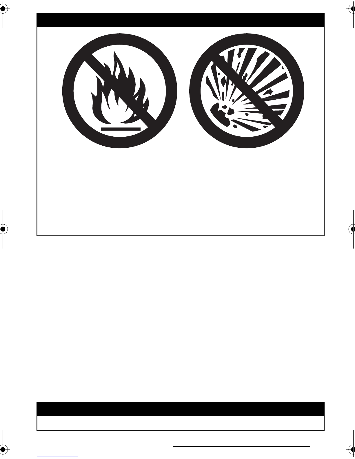
WARNING
V03M01Q
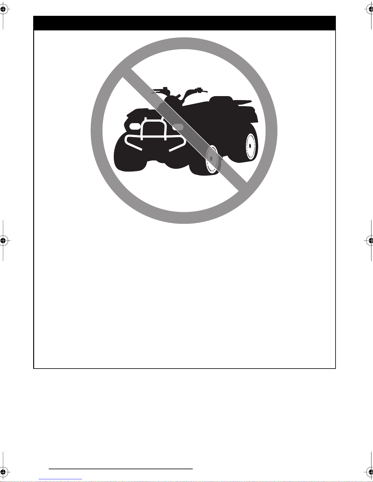
POTENTIAL HAZARD
Transporting inflammable or dangerous material can lead to explosions.
WHAT CAN HAPPEN
This can cause serious injury or death.
HOW TO AVOID THE HAZARD
Never transport inflammable or dangerous material.
While reading this Operator’s Guide, remember that:
Indicates a potential hazard that could result in serious injury or death.
WARNING
33
Page 36

BOMBARDIER LIMITED WARRANTY NORTH
AMERICA: 2002 BOMBARDIER
1. SCOPE OF THE LIMITED WARRANTY
BOMBARDIER INC. (hereinafter “BOMBARDIER”) warrants its 2002 Bombardier ATV
from defects in material or workmanship for the period described below.
All genuine BOMBARDIER parts and accessories, installed by an authorized BOMBARDIER
dealer (as hereinafter defined) at the time of delivery of the 2002 Bombardier ATV, carry the
same warranty as that of the ATV.
Tires and winches supplied as original equipment on your ATV are warranted separately
by the individual tire or winch manufacturer as identified below. If an original tire or
winch on your Bombardier ATV has a defect in material or workmanship, please contact
these manufacturers or ask your authorized BOMBARDIER dealer for assistance.
®
ATV
Carlisle Tire & Wheel Company
(Traxters and Quest tires)
23 Windham Boulevard
Aiken, SC 29805
Warranty Information:
in USA 1-800-260-7959
in Canada 1-800-265-6155
in Quebec 1-877-997-4999
Kenda USA (DS 650 tires)
7095 Americana Parkway
Reynoldsburg, OH 43068
1-614-866 9803
Use of the product for racing or any other competitive activity, at any point, even by a
prior owner, will render this warranty null and void.
2. WARRANTY COVERAGE PERIOD
This warranty will be in effect FROM THE DATE OF DELIVERY TO THE FIRST RETAIL
CONSUMER or the date the product is first put into use, whichever occurs first and
for a period of:
SIX (6) CONSECUTIVE MONTHS, for private use or commercial owners.
The repair or replacement of parts or the performance of service under this warranty
does not extend the life of this warranty beyond its original expiration date.
Warn Industries Inc. (Winch)
12900 SE Capps Road
Clackamas, Oregon 97015-8903
Customer service:
in USA 1-800-543-9276
in Canada 1-800-668-6012
in Quebec 1-800-361-9291
3. CONDITIONS TO HAVE WARRANTY COVERAGE
This warranty coverage is available only on 2002 Bombardier ATV purchased as new and
unused by its first owner from a BOMBARDIER dealer authorized to distribute Bombardier
ATV products in the country in which the sale occurred (hereinafter “BOMBARDIER
dealer”), and then only after the BOMBARDIER specified pre-delivery inspection pro-
cess is completed and documented. Warranty coverage only becomes available upon
proper registration of the product by a BOMBARDIER dealer. Such limitations are necessary in order to allow BOMBARDIER to preserve both the safety of its products, and
also that of its consumers and the public.
Routine maintenance outlined in the Operator’s Guide must be timely performed in
order to maintain warranty coverage. BOMBARDIER reserves the right to make warranty coverage contingent upon proof of proper maintenance.
34
Page 37

4. WHAT TO DO TO OBTAIN WARRANTY COVERAGE
The customer must notify a servicing BOMBARDIER dealer within two (2) days of the
appearance of a defect, and provide it with reasonable access to the product and reasonable opportunity to repair it. The customer must also present to the BOMBARDIER
dealer, proof of purchase of the product and must sign the repair/work order prior to
the start of the repair in order to validate the warranty repair. All parts replaced under
this limited warranty become the property of BOMBARDIER.
5. WHAT BOMBARDIER WILL DO
BOMBARDIER’s obligations under this warranty are limited to, at its sole discretion,
repairing parts found defective under normal use, maintenance and service, or replacing such parts with new genuine BOMBARDIER parts without charge for parts and
labor, at any authorized BOMBARDIER dealer.
BOMBARDIER reserves the right to improve or modify products from time to time
without assuming any obligation to modify products previously manufactured.
6. EXCLUSIONS - ARE NOT WARRANTED
• Normal wear and tear;
• Routine maintenance items, tune ups, adjustments;
• Damage caused by failure to provide proper maintenance and/or storage, as de-
scribed in the Operator’s Guide;
• Damage resulting from removal of parts, improper repairs, service, maintenance, modifications or use of parts not manufactured or approved by BOMBARDIER or resulting
from repairs done by a person that is not an authorized servicing BOMBARDIER dealer;
• Damage caused by abuse, abnormal use, neglect or operation of the product in a
manner inconsistent with the recommended operation described in the Operator’s
Guide;
• Damage resulting from accident, submersion, fire, theft, vandalism or any act of
God;
• Operation with fuels, oils or lubricants which are not suitable for use with the product (see the Operator’s Guide);
• Water or snow ingestion;
• Incidental or consequential damages, or damages of any kind including without
limitation towing, storage, telephone, rental, taxi, inconvenience, insurance coverage, loan payments, loss of time, loss of income.
7. LIMITATIONS OF LIABILITY
THIS WARRANTY IS EXPRESSLY GIVEN AND ACCEPTED IN LIEU OF ANY AND
ALL OTHER WARRANTIES, EXPRESSED OR IMPLIED, INCLUDING WITHOUT LIMITATION ANY WARRANTY OF MERCHANTABILITY OR FITNESS FOR A PARTICULAR PURPOSE. TO THE EXTENT THAT THEY CANNOT BE DISCLAIMED, THE IMPLIED WARRANTIES ARE LIMITED IN DURATION TO THE LIFE OF THE EXPRESS
WARRANTY. INCIDENTAL AND CONSEQUENTIAL DAMAGES ARE EXCLUDED
FROM COVERAGE UNDER THIS WARRANTY. SOME STATES/PROVINCES DO
NOT ALLOW FOR THE DISCLAIMERS, LIMITATIONS AND EXCLUSIONS IDENTIFIED ABOVE, AS A RESULT, THEY MAY NOT APPLY TO YOU. THIS WARRANTY
GIVES YOU SPECIFIC RIGHTS, AND YOU MAY ALSO HAVE OTHER LEGAL
RIGHTS WHICH MAY VARY FROM STATE TO STATE, OR PROVINCE TO PROVINCE.
Neither the distributor, any BOMBARDIER dealer nor any other person has been authorized to make any affirmation, representation or warranty regarding the product,
other than those contained in this limited warranty, and if made, shall not be enforceable against BOMBARDIER.
35
Page 38

BOMBARDIER reserves the right to modify this warranty at any time, being understood that such modification will not alter the warranty conditions applicable to the
products sold while this warranty is in effect.
8. TRANSFER
If the ownership of a product is transferred during the warranty coverage period, this
warranty shall also be transferred and be valid for the remaining coverage period provided that BOMBARDIER is notified of such transfer of ownership in the following way:
a) The former owner contacts BOMBARDIER (at the phone number provided below)
or an authorized BOMBARDIER dealer and gives the coordinates of the new owner;
or
b) BOMBARDIER or an authorized BOMBARDIER dealer receives a proof that the
former owner agreed to the transfer of ownership, in addition to the coordinates of
the new owner.
9. CONSUMER ASSISTANCE
a) In the event of a controversy or a dispute in connection with this BOMBARDIER
LIMITED WARRANTY, BOMBARDIER suggests that you try to resolve the issue at
the dealership level. We recommend discussing the issue with the authorized dealer’s service manager or owner.
b) If the issue has not yet been resolved, please submit your complaint in writing or
call the appropriate number below:
In Canada: in USA:
BOMBARDIER INC.
RECREATIONAL PRODUCTS
BOMBARDIER ATV
CUSTOMER ASSISTANCE CENTER
VALCOURT, QUEBEC
J0E 2L0
Tel: (819) 566-3366
© 2001 Bombardier Inc. All rights reserved
® Registered trademark of Bombardier Inc.
BOMBARDIER LIMITED WARRANTY INTERNATIONAL.
BOMBARDIER MOTOR
CORPORATION OF AMERICA
RECREATIONAL PRODUCTS
CUSTOMER ASSISTANCE CENTER
P.O. BOX 8035
7575 BOMBARDIER COURT
WAUSAU WI 54402-8035
Tel: (715) 848-4957
Fax: (715) 847-6879
36
Page 39

BOMBARDIER LIMITED WARRANTY
INTERNATIONAL: 2002 BOMBARDIER
1. SCOPE OF THE LIMITED WARRANTY
BOMBARDIER INC. (hereinafter “BOMBARDIER”) warrants its 2002 BOMBARDIER
ATV from defects in material or workmanship for the period described below.
All genuine BOMBARDIER parts and accessories, installed by an authorized BOMBARDIER
distributor/dealer (as hereinafter defined) at the time of delivery of the 2002 BOMBARDIER
ATV, carry the same warranty as that of the ATV.
Tires and winches supplied as original equipment on your ATV are warranted separately
by the individual tire or winch manufacturer as identified below. If an original tire or
winch on your BOMBARDIER ATV has a defect in material or workmanship, please
contact these manufacturers or ask your authorized BOMBARDIER distributor/dealer
for assistance.
®
ATV
Carlisle Tire & Wheel Company
(Traxters and Quest tires)
23 Windham Boulevard
Aiken, SC 29805
Warranty Information:
International: 1-803-643-2900
Kenda USA (DS 650 tires)
7095 Americana Parkway
Reynoldsburg, OH 43068
1-614-866-9803
Use of the product for racing or any other competitive activity, at any point, even by
a prior owner will render this warranty null and void.
2. WARRANTY COVERAGE PERIOD
This warranty will be in effect FROM THE DATE OF DELIVERY TO THE FIRST RETAIL
CONSUMER or the date the product is first put into use, whichever occurs first and
for a period of:
SIX (6) CONSECUTIVE MONTHS for private use or commercial owners.
The repair or replacement of parts or the performance of service under this warranty
does not extend the life of this warranty beyond its original expiration date.
Warn Industries Inc. (Winch)
12900 SE Capps Road
Clackamas, Oregon 97015-8903
Customer service:
International: 1-503-722-1200
3. CONDITIONS TO HAVE WARRANTY COVERAGE
This warranty coverage is available only on 2002 BOMBARDIER ATV purchased as new
and unused by its first owner from a BOMBARDIER distributor/dealer authorized to
distribute BOMBARDIER ATV products in the country in which the sale occurred (hereinafter “BOMBARDIER distributor/dealer”), and then only after the BOMBARDIER
specified pre-delivery inspection process is completed and documented. Warranty coverage only becomes available upon proper registration of the product by a BOMBARDIER
distributor/dealer. Such limitations are necessary in order to allow BOMBARDIER to
preserve both the safety of its products, and also that of its consumers and the public.
Routine maintenance outlined in the Operator’s Guide must be timely performed in
order to maintain warranty coverage. BOMBARDIER reserves the right to make warranty coverage contingent upon proof of proper maintenance.
37
Page 40

4. WHAT TO DO TO OBTAIN WARRANTY COVERAGE
The customer must notify a servicing BOMBARDIER distributor/dealer within two (2)
days of the appearance of a defect, and provide it with reasonable access to the product and reasonable opportunity to repair it. The customer must also present to the
BOMBARDIER distributor/dealer, proof of purchase of the product and must sign the
repair/work order prior to the start of the repair in order to validate the warranty repair.
All parts replaced under this limited warranty become the property of BOMBARDIER.
5. WHAT BOMBARDIER WILL DO
BOMBARDIER’s obligations under this warranty are limited to, at its sole discretion,
repairing parts found defective under normal use, maintenance and service, or replacing such parts with new genuine BOMBARDIER parts without charge for parts and
labor, at any authorized BOMBARDIER distributor/dealer.
BOMBARDIER reserves the right to improve or modify products from time to time
without assuming any obligation to modify products previously manufactured.
6. EXCLUSIONS - ARE NOT WARRANTED
• Normal wear and tear;
• Routine maintenance items, tune ups, adjustments;
• Damage caused by failure to provide proper maintenance and/or storage, as de-
scribed in the Operator’s Guide;
• Damage resulting from removal of parts, improper repairs, service, maintenance, modifications or use of parts not manufactured or approved by BOMBARDIER or resulting
from repairs done by a person that is not an authorized servicing BOMBARDIER
distributor/dealer;
• Damage caused by abuse, abnormal use, neglect or operation of the product in a
manner inconsistent with the recommended operation described in the Operator’s
Guide;
• Damage resulting from accident, submersion, fire, theft, vandalism or any act of
God;
• Operation with fuels, oils or lubricants which are not suitable for use with the
product (see the Operator’s Guide);
• Water or snow ingestion;
• Incidental or consequential damages, or damages of any kind including without
limitation towing, storage, telephone, rental, taxi, inconvenience, insurance coverage, loan payments, loss of time, loss of income.
7. LIMITATIONS OF LIABILITY
THIS WARRANTY IS EXPRESSLY GIVEN AND ACCEPTED IN LIEU OF ANY AND
ALL OTHER WARRANTIES, EXPRESSED OR IMPLIED, INCLUDING WITHOUT
LIMITATION ANY WARRANTY OF MERCHANTABILITY OR FITNESS FOR A PARTICULAR PURPOSE. TO THE EXTENT THAT THEY CANNOT BE DISCLAIMED,
THE IMPLIED WARRANTIES ARE LIMITED IN DURATION TO THE LIFE OF THE
EXPRESS WARRANTY. INCIDENTAL AND CONSEQUENTIAL DAMAGES ARE
EXCLUDED FROM COVERAGE UNDER THIS WARRANTY. SOME STATES/
PROVINCES DO NOT ALLOW FOR THE DISCLAIMERS, LIMITATIONS AND EXCLUSIONS IDENTIFIED ABOVE, AS A RESULT, THEY MAY NOT APPLY TO YOU.
THIS WARRANTY GIVES YOU SPECIFIC RIGHTS, AND YOU MAY ALSO HAVE
OTHER LEGAL RIGHTS WHICH MAY VARY FROM STATE TO STATE, OR PROVINCE TO PROVINCE.
38
Page 41

Neither the distributor, any BOMBARDIER dealer nor any other person has been authorized to make any affirmation, representation or warranty regarding the product,
other than those contained in this limited warranty, and if made, shall not be enforceable against BOMBARDIER.
BOMBARDIER reserves the right to modify this warranty at any time, being understood that such modification will not alter the warranty conditions applicable to the
products sold while this warranty is in effect.
8. TRANSFER
If the ownership of a product is transferred during the warranty coverage period, this
warranty shall also be transferred and be valid for the remaining coverage period provided that BOMBARDIER is notified of such transfer of ownership in the following
way:
a) The former owner contacts BOMBARDIER or an authorized BOMBARDIER
distributor/dealer and gives the coordinates of the new owner; or
b) BOMBARDIER or an authorized BOMBARDIER distributor/dealer receives a proof
that the former owner agreed to the transfer of ownership, in addition to the coordinates of the new owner.
9. CONSUMER ASSISTANCE
a) In the event of a controversy or a dispute in connection with this BOMBARDIER
LIMITED WARRANTY, BOMBARDIER suggests that you try to resolve the issue
at the distributorship/dealership level. We recommend discussing the issue with
the authorized dealer’s service manager or owner.
b) If further assistance is required, the distributor’s service department should be
contacted in order to resolve the matter.
© 2001 Bombardier Inc. All rights reserved
® Registered trademark of Bombardier Inc.
39
Page 42

FREQUENTLY ASKED QUESTIONS
Q: Why must my vehicle be registered with the factory? After all, I do have my
original invoice as proof of when I purchased my vehicle.
A: Registration is very important and an authorized Bombardier ATV dealer
must register your vehicle with Bombardier Inc. Make sure the card has
been sent. All of this will allow you to:
a) Have warranty work performed at any authorized Bombardier ATV dealer
in North America. Your registration card will provide the dealer with all
the necessary data to complete warranty claim forms.
b) Be advised by Bombardier Inc. should there be a safety recall or a partic-
ular warranty campaign.
c) Be contacted much faster by the police, in the event that they find your
vehicle subsequent to a theft.
Q: Why must my vehicle be registered with the governing body having jurisdic-
tion over vehicle use?
A: Vehicle registration has two purposes: In many provinces or States, it is
mandatory to register a vehicle in the same way as for a car. It allows the
State or province to maintain records of existing vehicles. In some juridictions, governmental agencies use part of the registration fees for establishing and maintaining trails.
Q: Where can I find information on the lubrication and maintenance of my vehicle?
A: In the Operator’s Guide provided with the vehicle at the time of delivery.
Q: Will the entire warranty be voided or cancelled, if I do not operate or maintain
my new vehicle exactly as specified in the Operator’s Guide?
A: The warranty of the new vehicle cannot be “Voided” or “Cancelled” if
predelivered by an authorized Bombardier ATV dealer. However, if a particular failure is caused by operation or maintenance other than is shown in
the Operator’s Guide, THAT failure may not be covered under warranty. This
includes service work performed by the customer, oil and filter change and
especially the critical adjustments such as the carburetor.
Q: Would you give some examples of abnormal use or strain, neglect or abuse
which may affect the limited warranty coverage?
A: These terms are general and overlap each other in some cases. Some spe-
cific examples may include: running the engine out of oil, operating the
vehicle with a broken or damaged part which causes another part to fail,
and so on. If you have any specific questions on operation or maintenance,
please contact an authorized Bombardier ATV dealer for advice.
Q: What costs are my responsibility during the warranty period?
A: The customer’s responsibility includes all costs of normal maintenance ser-
vices, non-warranty repairs, accidents and collision damage, as well as oils,
and spark plugs, and incidental or consequential damages costs as explained in the warranty.
40
Page 43

Q: Are “Genuine” Bombardier replacement parts used in warranty repairs also
covered by the limited warranty coverage?
A: Yes. When installed by an authorized Bombardier ATV dealer, any “Genuine”
Bombardier part used in warranty repairs assumes the remaining warranty
that exists on the vehicle.
Q: If I sell my vehicle within the warranty period, will the new owner qualify for
the balance of the limited warranty coverage?
A: Yes, provided the re-sale has been registered with the manufacturer.
Q: How can I receive the best owner assistance?
A: The satisfaction, safety and goodwill of the owners of Bombardier products
are of primary concern to your ATV dealer and Bombardier Inc. Normally,
any problems that arise in connection with the sales transaction or the operation of your vehicle will be handled by your Dealer’s Sales or Service
Departments. It is recognized, however, that despite the best intentions of
everyone concerned, misunderstandings will sometimes occur. Frequently,
complaints are the result of a breakdown in communications and can quickly be resolved by a member of the dealership management. If the problem
already has been reviewed with the Sales Manager or Service Manager,
contact the Dealer Principal himself or the General Manager.
We are always pleased to receive your comments on the Bombardier ATV.
EMISSION REQUIREMENTS
The California Air Resources Board (CARB) requires that your ATV observe with
applicable exhaust emissions standards during its useful life, when operated and
maintained according to the instructions supplied.
A non-compliance Red Label (as well as a Green Label) is obtained annually during
California Vehicle registration. The appropriate label is denoted by the vehicle
identification number (in the 8
VEHICLE CATEGORY VIN 8th CHARACTER
Non-complying Red Label Must denote a C or 3
Complying Green Label Any alphanumeric designation other than a C or 3
th
character detailed herein).
41
Page 44

LOCATION OF THE IMPORTANT LABELS
The following labels are on your ATV. If missing or damaged, they can be replaced
free of charge. See an authorized Bombardier ATV dealer.
5
9 3
11
4
2
1
5
6
10
12
5 4
7
9
8
5
V04M03L
42
Page 45

Label 1
Label 4
V01M04Z
Label 5
V01M050
V01M01Z
V01M02Z
Label 6
Label 2
V01M06Z
Label 7
Label 3
V01M03Z
V01M07Z
43
Page 46

Label 8 Label 9
V01M09Z
Label 10
V01M0BZ
V04M07Y
Label 11
V04M08Y
Label 12
V04M0AL
44
Page 47

HOW TO IDENTIFY YOUR ATV
The main components of your vehicle (engine and frame) are identified by different serial numbers. It may sometimes become necessary to locate these numbers for warranty purposes or to trace your vehicle in the event of loss. These
numbers are required by the authorized Bombardier ATV dealer to complete warranty claims properly. No warranty will be allowed by Bombardier Inc. if the engine
identification number (EIN) or vehicle identification number (VIN) is removed or
mutilated in any way. We strongly recommend that you take note of all the serial
numbers on your vehicle and supply them to your insurance company.
Engine and Vehicle Identification Number Location
1
V04M06L
1. EIN (Engine Identification Number)
2. VIN (Vehicle Identification Number)
3. Model
2
3
45
Page 48
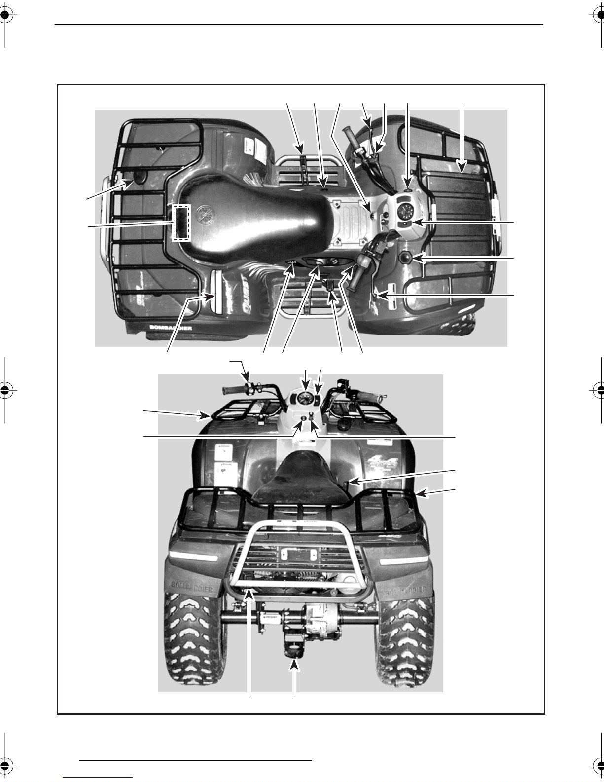
CONTROLS/INSTRUMENTS/EQUIPMENTS
NOTE: Some controls/instruments/equipments are optional.
18
15 254314 19
24
20
21
11
22 5 16 1
6,7,8
17
10 9
9
13
2
12
5
21
V04A04L
46
26
23
Page 49
While reading this Operator’s Guide, remember that:
WARNING
Indicates a potential hazard that could result in serious injury or death.
NOTE: This section gives basic func-
tions of the various controls of your
ATV. For more details of how to operate one control in conjunction with
some others, refer to OPERATING INSTRUCTIONS in this Operator’s Guide
and Safety Handbook.
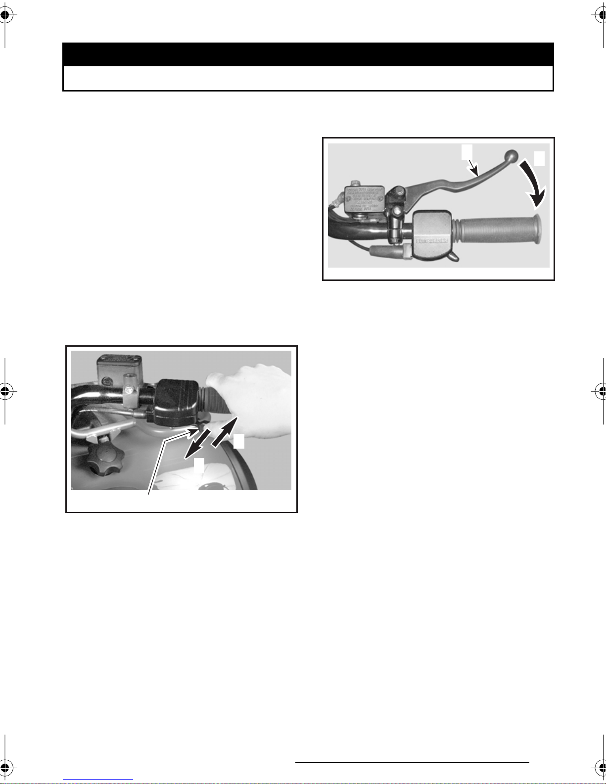
1) Throttle Lever
Located on the right side of handlebar.
When pushed, it increases the engine
speed that allows the engagement of
the transmission on the selected gear.
When released, the engine speed
should return automatically to idle and
the vehicle will gradually slow down.
2
3
V01I02Y
1. Throttle lever
2. To accelerate
3. To decelerate
1
2) Front Brake Lever
Located on the right side of handlebar.
When compressed, the brake is applied. When released, it should automatically return to its original position.
Braking effect is proportional to the
force applied on the lever and to the
type and condition of the terrain. The
front brake will have also an effect on
rear wheels through the drive train.
See the note at Rear Brake Lever below for additional information.
1
V00K01Y
1. Brake lever
2. To apply brake
2
3) Rear Brake Lever
Located on the left side of handlebar.
When compressed, the brake is applied. When released, it should automatically return to its original position.
Braking effect is proportional to the
force applied on the lever and to the
type and condition of the terrain.
NOTE: Using the rear brake will have
also an effect on front wheels because
they are interconnected through the
drive train. As on other wheeled vehicles, the vehicle weight is transferred
to the front wheels when braking. To
obtain greater stopping efficiency, the
brake system distributes more braking
force to the front wheels. This will affect vehicle handling and steering control when braking vigorously. Take it
into account when braking.
47
Page 50
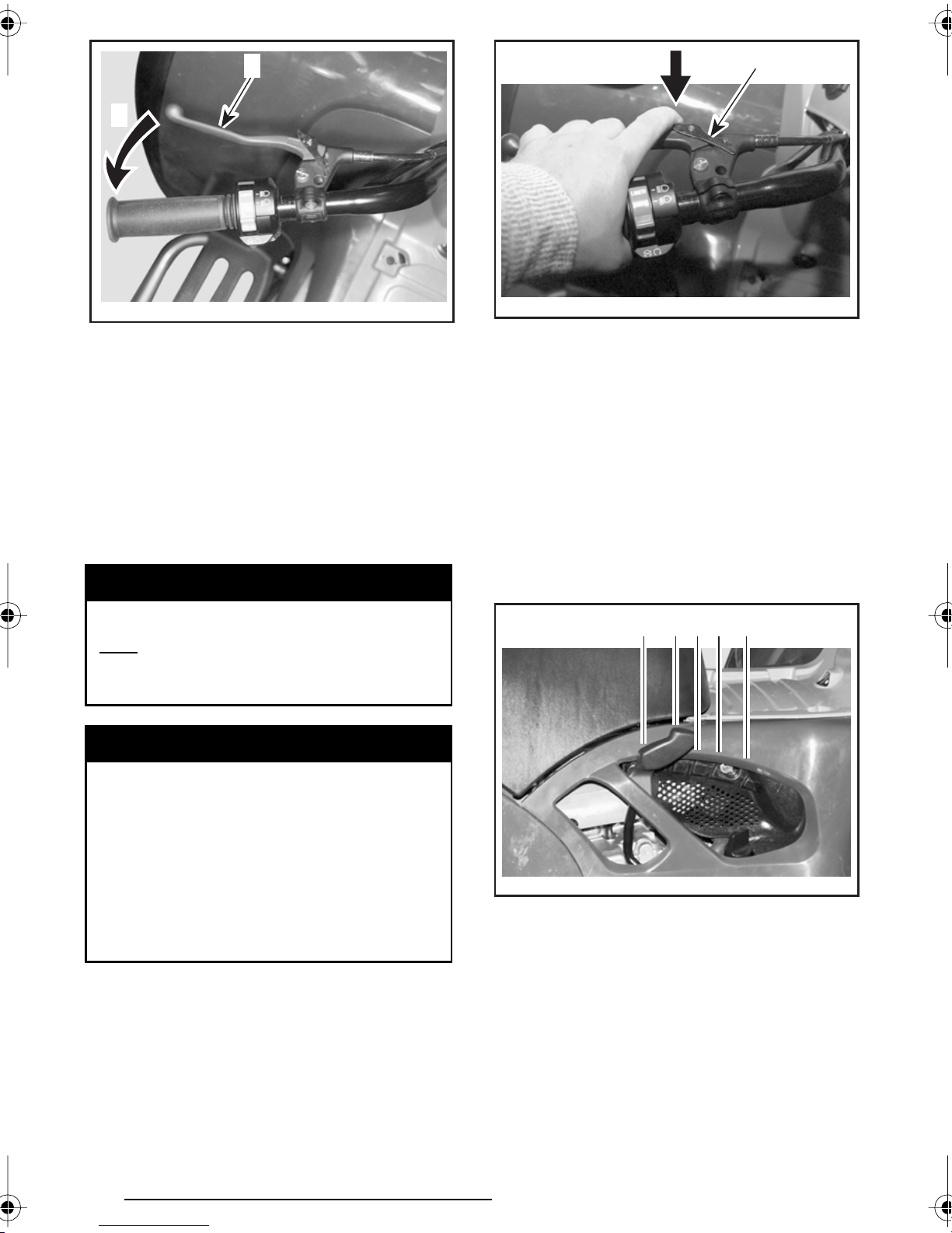
1
2
1
2
V04K01Y
1. Brake lever
2. To apply brake
4) Brake Lever Lock
Located on left side of handlebar on
the rear brake lever. When applied, it
prevents the vehicle from moving.
Useful when the brake needs to be
locked for example such as doing a Kturn.
WARNING
Always use the brake lever lock
engage the PARK position on
and
the transmission lever when the
vehicle is not in operation.
WARNING
V04K02Y
1. Brake lever lock
2. To apply parking brake
To release mechanism: Squeeze brake
lever. Lever lock should automatically return to its original position. Brake lever
should return to rest position. Always release brake lever lock before riding.
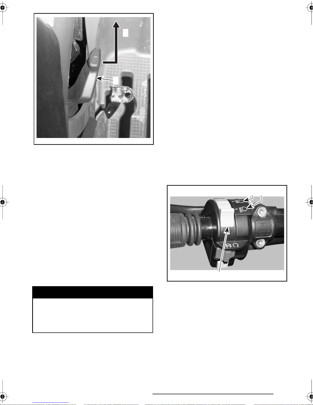
5) Transmission Lever
Located on the right side of vehicle. A
5-position lever: P, R, N, H and L.
P
R NH L
Make sure brake lever lock is fully
disengaged before operating the
ATV.
When you ride the vehicle, the prolonged use of brakes may cause
damage to the brake system and
cause loss of braking capacity
and/or fire.
To engage mechanism: Squeeze
brake lever and maintain while moving
lever lock with a finger. Brake lever is
now compressed and applying rear
brakes.
48
V04E01Y
To change the transmission position,
completely stop vehicle then move lever to the right then to the desired position while moving lever forward. Do
not force lever. If unable to shift, gently
apply throttle to move ATV and try
again.
Page 51
N: Neutral
This position disengages the transmis-
2
sion to allow manual vehicle movement or towing.
H: High gear
This selects the high speed range of the
transmission in the gear box. It is the
normal driving speed range. It allows the
1
vehicle to reach its maximum speed.
L: Low gear
This selects the low speed range of
the transmission in the gear box. It is
the working position. It allows the vehicle to move slowly with the maximum traction and power.
V04E02Y
1. Transmission lever
2. To change position
CAUTION: Always completely stop
the vehicle and apply the brake prior
to moving the transmission lever.
P: Park
This position locks the transmission to
help prevent vehicle movement. Always use when the vehicle is not in
operation. In some circumstances, it
may be necessary to rock the vehicle
back and forth to move the gears in the
transmission to allow the park to be
engaged.
R: Reverse
This allows the vehicle to go backward.
The vehicle speed is limited.
WARNING
Before moving vehicle in reverse,
ensure the path behind is clear of
obstacles or bystanders. Remain
seated.
6) Headlight Switch
Located on left side of handlebar. Place
switch to LO for the low beam and taillight. Place switch to HI for the high
beam and taillight.
3 2
V01G19Y
1. Headlight switch
2. Low beam position
3. High beam position
NOTE: Place ignition switch to ON
“without light” position to close the
headlight.
1
49
Page 52
V01G1AY
ON POSITION “WITHOUT LIGHT”
V01G190
1. Start button
1
7) Engine Stop Switch
Located on left side of handlebar. The
engine will turn over but will not start
if the engine stop switch is turned to
OFF position.
This switch can be used to stop engine
and as an emergency control.
NOTE: While engine can be stopped
by turning ignition key OFF, we recommend the engine be stopped by the
engine stop switch.
To stop engine, fully release throttle lever then use the engine stop switch.
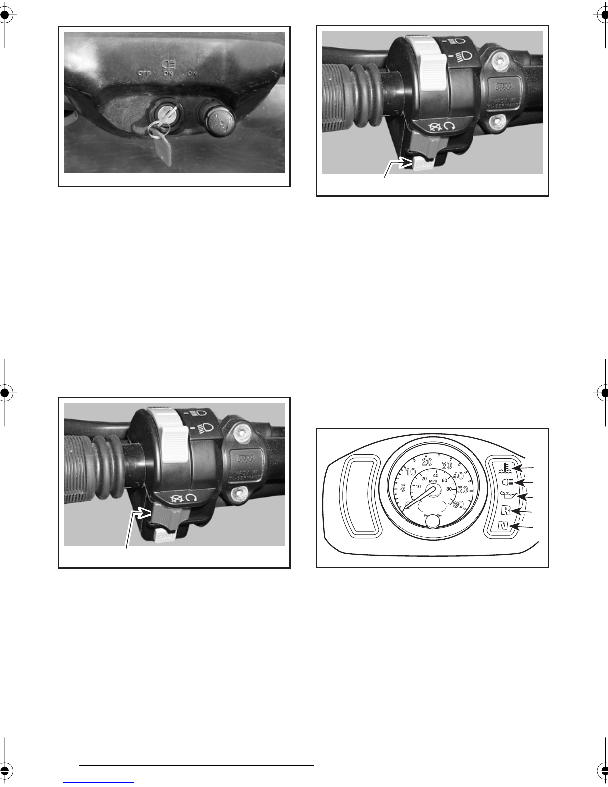
9) Indicator Lights Cluster
NOTE: When first turning switch to
ON (either position), the oil pressure
indicator light will turn on for a brief
moment. This validates its operation.
Thereafter, only the lights that are activated will remain on (Reverse, Neutral and high intensity lights).
Located on right side of cluster. They
light up to monitor different functions.
1
2
3
4
5
V01G19Z
1. Engine stop switch
1
8) Start Button
Located on left side of handlebar.
To start engine, place the engine stop
switch to RUN.
Press and hold the start button. Release
immediately after engine is started.
50
V00I01Y
1. Engine temperature
2. High intensity
3. Oil pressure
4. Reverse
5. Neutral
Engine Temperature
When indicator light is ON, it indicates
the engine is overheating.
If engine overheats, refer to Engine
Overheat in SPECIAL PROCEDURES.
Page 53

High Intensity
Odometer/Trip Meter
When the indicator light is ON, it indicates the high intensity is selected on
the headlights.
Oil Pressure
When continuously ON, it indicates a
low oil pressure condition of the engine. Refer to Limp Home Mode in
SPECIAL PROCEDURES.
This light turns on when the ignition
switch is turned ON and remains on
until engine is running.
CAUTION: If the light does not turn
off right after engine starting, stop
engine. See an authorized Bombardier ATV dealer. Do not use the vehicle until repaired.
Reverse
When lit, it indicates the transmission
is engaged in reverse.
Combined LCD (Liquid Crystal Display)
display. Odometer records the total
distance traveled in miles. The trip
meter records the distance traveled in
miles until it is reset. The last right digit indicates the tenth of a mile. It can
be used to approximately monitor the
fuel tank range or distance between
two locations for instance.
Display Selection Button
The odometer always appears when
turning the ignition switch ON (either
position). To change the display to the
trip meter, momentarily press the button on the speedometer.
To reset the trip meter, push and HOLD
button until all numbers read zero
(while in trip meter selection).
Neutral
When lit, it indicates the transmission
is in neutral position.
10) Speedometer
Located in center of cluster. It indicates the speed of the vehicle in MPH
and km/h. The speedometer is backlit
when the ignition switch is turned on
(either position).
V00I04Y
Press once to switch from odometer to
tripmeter or vice versa. Press and hold
to reset while in trip meter selection.
V00I01Z
1. Speedometer
2. Odometer/trip meter
3. Display selection button
2 31
51
Page 54
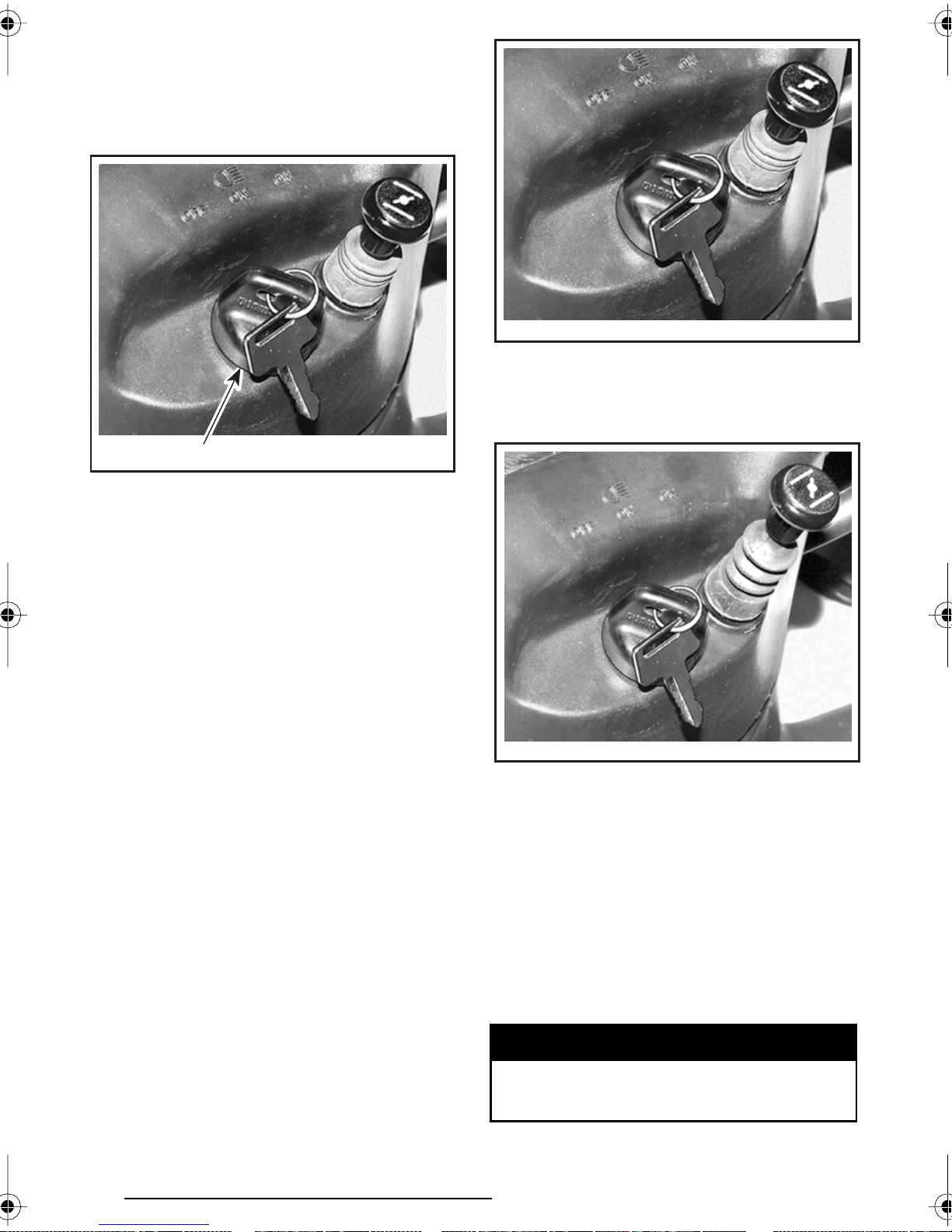
11) Ignition Switch
Located at bottom of cluster.
Key-operated, 3-position switch: OFF,
ON with lights and ON without lights.
V01I17Z
CHOKE KNOB LEVER IN THE OFF POSITION
The full choke position is used for lower temperature (fully extended).
V01I17Y
1. Ignition switch
1
Insert key in switch and turn to the desired position. To remove key, turn key
to OFF then pull it out.
The ON with lights position, turns on
all lights with either the engine running
or not. Remember that having the
lights on without the engine running
discharges the battery. Always turn ignition to OFF after engine has been
stopped.
NOTE: While engine can be stopped
by turning ignition key OFF, we recommend the engine be stopped by the
engine stop switch.
12) Choke Knob Lever
V01I18Y
CHOKE LEVER IN THE FULL CHOKE
POSITION
The other positions between OFF and
FULL position, will be use depending
on the temperature.
Located at bottom of cluster. This device features a variable lever to ease
cold start.
Position OFF is for normal use with a
warm engine (pushed in).
52
13) Fuel Tank Cap
Unscrew counterclockwise and remove
cap to allow fuel tank filling then fully
tighten clockwise.
WARNING
Never use an open flame to check
fuel level.
Page 55
14) Fuel Gauge
Located in front of seat under cluster,
the gauge shows an approximate
amount of the fuel in tank.
A
B
V01L0IY
A. Empty
B. 1/4
C. 1/2
D. 3/4
E. Full
C
E
D
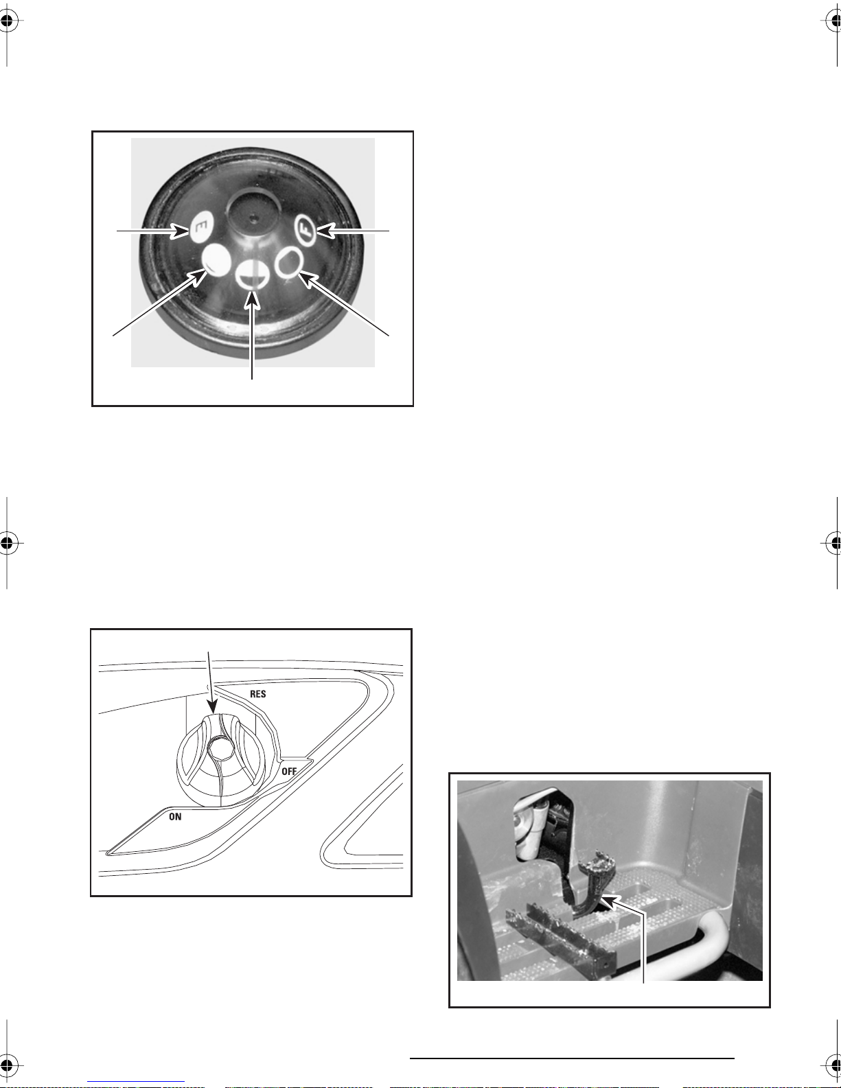
15) Fuel Valve
Located on left side panel under front
part of seat. 3-position rotary valve:
OFF, ON, RES. Rotate the knob to align
its pointer with ON, OFF or RES.
1
CAUTION: Turn valve to OFF position when ATV is not being operated
or when transporting.
ON
Allows fuel to flow to carburetor. This
is the normal position for operation of
the vehicle.
RES (RESERVE)
When fuel is exhausted in the fuel tank
when in the ON position, an emergency supply of fuel is available by turning
the knob to RES. The reserve contains
approximately 30% of the fuel tank capacity. Use only this position when the
ON supply is empty.
When down to the reserve, refuel as
soon as possible. Ensure to turn the
valve back to the ON position after refuelling.
CAUTION: Improper opening of fuel
valve will restrict the flow of fuel.
Make sure valve is fully opened while
running.
16) Rear Brake Pedal
Located on the right footpeg. When
pressed down, the brake is applied.
When released, it should return to its
original position. Braking effect is proportional to the force applied on the lever and to the type and condition of the
terrain.
V04A06Y
1. Align this pointer toward the desired position
OFF
Stops fuel supply to carburetor.
NOTE: The brake will have also an effect on front wheels through the drive
train.
V04K03Y
1. Rear brake pedal
1
53
Page 56

17) Rewind Starter Handle
(if so equipped)
The rewind starter handle is provided
as an emergency starting device.
Follow the usual starting procedure;
but use the rewind starter instead of
the electric starter.
Located on right side panel under seat.
Auto-rewind type. To engage mechanism, pull handle slowly until a resistance is felt then continue to slowly
pull the handle until the compression
stroke peak (strong rotating resistance) is overpassed then, pull vigorously. Slowly release handle.
The compartment is equipped with a
drain plug under the tool box. Remove
plug to allow draining when necessary.
Reinstall plug when finished.
12
18) Footpeg
Located on footrest. Use this area to
maintain your feet stable.
V04L01Y
1. Footpeg
1
19) Storage Compartment
Located in front of vehicle. Convenient
location to carry personal articles such
as an a helmet, spare spark plugs, first
aid kit, etc. Unlatch cover, gently lift
then remove cover.
V01L07Y
1. Removing cover
2. Tool box
It also contains the Operator’s Guide
and Safety Handbook that should be
kept in a waterproof bag and remain
with the vehicle at all times.
WARNING
Never leave any heavy or loose
breakable objects in the storage
basket. Always latch cover before riding. If storage cover is removed to provide greater carrying area, ensure that cargo is
secured and will not “fly out”
when riding at speed on rough
terrain. Slow down.
Too l Box
Located in storage compartment. The
tool box contains tools for basic maintenance, the Operator’s Guide and the
Safety Handbook.
54
Page 57
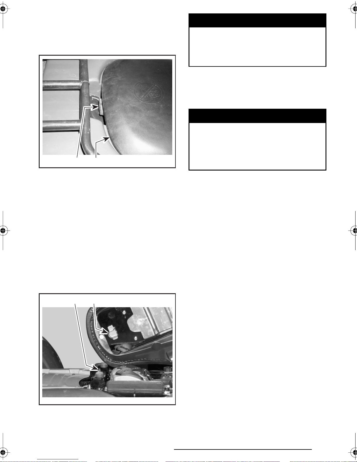
20) Seat Latch
Located underneath rear end of seat.
It allows the removal of seat to give
access to engine compartment.
V00A11Y
1. Seat
2. Seat latch
Seat Removal
12
WARNING
Periodically verify the seat lock pin
and tighten if needed. Make sure
seat is securely latched before
riding.
21) Front/Rear Cargo Racks
Located on top of chassis at front and
rear. Convenient racks to carry gear.
WARNING
Ensure to properly secure material to rack. Do not overload. Ensure load does not interfere with
visibility and/or steering. Do not
carry passenger(s).
Refer to SPECIFICATIONS for carrying
loads and cargo weight distribution
recommendations.
Pull latch upward while gently lifting
rear of seat. Pull seat rearward. Continue lifting movement until you can release the front retaining device then
completely remove seat.
Seat Installation
Insert front tab of seat into frame hook.
When seat rests in its position, firmly
push seat down to latch.
2
1
22) Air Duct
Located on rear fenders. They force
the flow of air to cool radiator.
CAUTION: Do not place anything
over air intake ducts.
V04L02Y
1. Insert this tab in hook
2. Hook
55
Page 58

23) Trailer Hitch
Located on rear axle. Convenient hitch
to install a ball to tow a trailer or other
equipment. Install the proper ball size
as per trailer manufacturer recommendations. Refer to SPECIFICATIONS for
carrying loads and towing recommendations.
1
V00L01Y
1. Trailer hitch
WARNING
1
Ensure to install the proper ball
size that matches the equipment
you will tow.
NOTE: Follow manufacturer instruc-
tions for proper attachment.
24) Radiator Cap
Located at rear of rear fender. It provides access to the radiator filling neck.
Pull the protector cap to give access to
the radiator cap. When finished, properly reinstall radiator cap then protector cap.
V01L0EY
1. Protector cap
2. Radiator cap
2
25) 12-Volt Power Outlet
It is located on left side of cluster.
Convenient for handheld spotlight or
other portable equipment.
Remove cap to use. Always reinstall pro-
tective cap after use to protect against
weather.
56
V01L0FY
TYPICAL
1. Protective cap
2. Power outlet
12
Page 59

Do not exceed the rating capacity. See
SPECIFICATIONS.
An auxiliary supply is available to connect additional accessories through a
connector at the rear of vehicle. See an
authorized Bombardier ATV dealer for
more details.
26) Fuses
Winch Control Switch
(if so equipped)
Located on the LH side of the front
fender.
To take out wire rope from winch, turn
switch button counterclockwise.
To get wire rope into the winch, turn
the switch button clockwise.
The electrical system is protected with
fuses. Refer to MAINTENANCE for details.
The fuse block is located at the rear of
the vehicle, on left side, under fender.
V04G01Y
1. Fuse block
1
Winch (if so equipped)
Located behind front skid plate.
Refer to ATV Winch Operator’s Manual for more informations.
2
V01A1KY
1. In
2. Out
1
Fairlead (if so equipped)
Located on the front skid plate.
The fairlead is used to prevent the
damages to the vehicle and guide the
wire rope into the winch.
V01A1OY
1. Winch
2. Front skid plate
1
2
V01A1OZ
1. Front skid plate
2. Fairlead
2
1
57
Page 60

LIQUIDS
While reading this Operator’s Guide, remember that:
WARNING
Indicates a potential hazard that could result in serious injury or death.
This section specifies the recommended liquids and procedures to check
their levels. Refer to MAINTENANCE
for procedures to replace the liquids.
Fuel
Recommended Fuel
Use regular unleaded gasoline or gasohol containing less than 10% of ethanol or methanol, available from most
service stations. The gasoline used
must have an octane number of 87
((R + M)/2) or higher.
NOTE: In most service station, pump
octane number corresponds to
(R + M)/2 octane number. Usually a
sticker can be found on the pump.
CAUTION: Never experiment with
other fuels. The use of unrecommended fuel can result in vehicle
performance deterioration and damage to critical parts in the fuel system and engine components.
CAUTION: Never mix oil with fuel.
This ATV has a 4-stroke engine. Oil
must be added to engine base only.
Fuel Level
WARNING
Never top up the fuel tank before
placing the vehicle in a warm area.
As temperature increases, fuel expands and may overflow. Fuel is
flammable and explosive under
certain conditions. Always wipe
off any fuel or oil spillage from the
vehicle.
Engine/ Transmission Oil
Recommended Oil
Use 4-stroke engine oil that meets or
exceeds the requirements for API service classification SG, SH or SJ. Always check the API service label on
the oil container to be sure it includes
the letters SG, SH or SJ. Only use highquality high-detergent oil.
NOTE: The same oil lubricates both
engine and transmission. For improved
overall performance and wear protection use Bombardier synthetic oil (P/N
293 600 039).
58
Page 61

Oil Viscosity
SAE 10W40 is recommended for summer time.
SAE 5W30 is recommended for winter time.
For other viscosity see applicative chart below.
°C
60
50
40
30
SAE 20W50
20
SAE 15W40
10
°F
140
120
100
80
60
V01A38L
SAE 10W40
0
SAE 10W30
-10
SAE 5W30
BOMBARDIER SYNTHETIC OIL 5W40 (P/N 293 600 039)
-20
-30
40
20
0
-20
59
Page 62

Oil Level
4. Add oil up to upper mark if required.
CAUTION: Check level frequently
and refill if necessary. Do not overfill.
Operating the engine/transmission
with an improper level may severely
damage engine/transmission. Wipe
off any spillage.
V04C01Y
RH SIDE OF ENGINE
1. Dipstick
1
5. To add oil, remove dipstick. Place a
funnel into the dipstick tube and fill
with the recommended oil. Do not
overfill.
V04C03Y
With vehicle on a level surface and engine cold, not running, check the oil
level as follows:
1. Unscrew dipstick then remove it and
wipe clean.
2. Reinstall dipstick, screw in it completely.
3. Remove and check oil level. It should
be near or equal to the upper mark.
1
3
2
6. Properly tighten dipstick.
Engine Coolant
Recommended Coolant
Always use ethylene-glycol antifreeze
containing corrosion inhibitors specifically for internal combustion aluminum
engines.
Cooling system must be filled with water and antifreeze solution (50% water,
50% antifreeze).
Coolant Level
WARNING
Check coolant level with engine
cold. Never add coolant in cooling system when engine is hot.
V04C02Y
1. Full
2. Add
3. Operating range
60
Page 63

Remove seat.
V04C05Y
Brake Fluid
Recommended Fluid
Always use brake fluid meeting the
specification DOT 4 only.
CAUTION: Never use other type of
oil such as mineral-based or synthetic oil.
Fluid Level
With vehicle on a level surface, check
brake fluid in reservoir for proper level.
It should be above MIN. mark.
Add fluid as required. Do not overfill.
Clean filler cap before removing.
CAUTION: Use only DOT 4 brake fluid from a sealed container.
NOTE: A low level may indicate leaks
or worn brake pads. See an authorized
Bombardier ATV dealer.
With vehicle on a level surface, liquid
should be between MIN. and MAX.
level marks of coolant reservoir.
NOTE: When checking level at temperature lower than 20°C (69°F), it may
be slightly lower than MIN. mark.
Add coolant up to MAX. mark if required. Use a funnel to avoid spillage.
Do not overfill.
Properly reinstall and tighten filler cap
and reinstall seat.
If the coolant is added in the coolant
reservoir, check the level in the radiator too. Add coolant if necessary.
NOTE: A cooling system that frequently requires coolant is the indication of
leaks or engine problems. See an authorized Bombardier ATV dealer.
Front Brake Fluid Reservoir
Turn steering in the straight-ahead position to ensure reservoir is level.
Check the brake fluid level, the reservoir is full when the fluid reaches of the
top of window.
Visually inspect lever boot condition.
Check for cracks, tears, etc. Replace if
damaged.
V04K04Y
Coolant Replacement
Refer to MAINTENANCE section.
61
Page 64
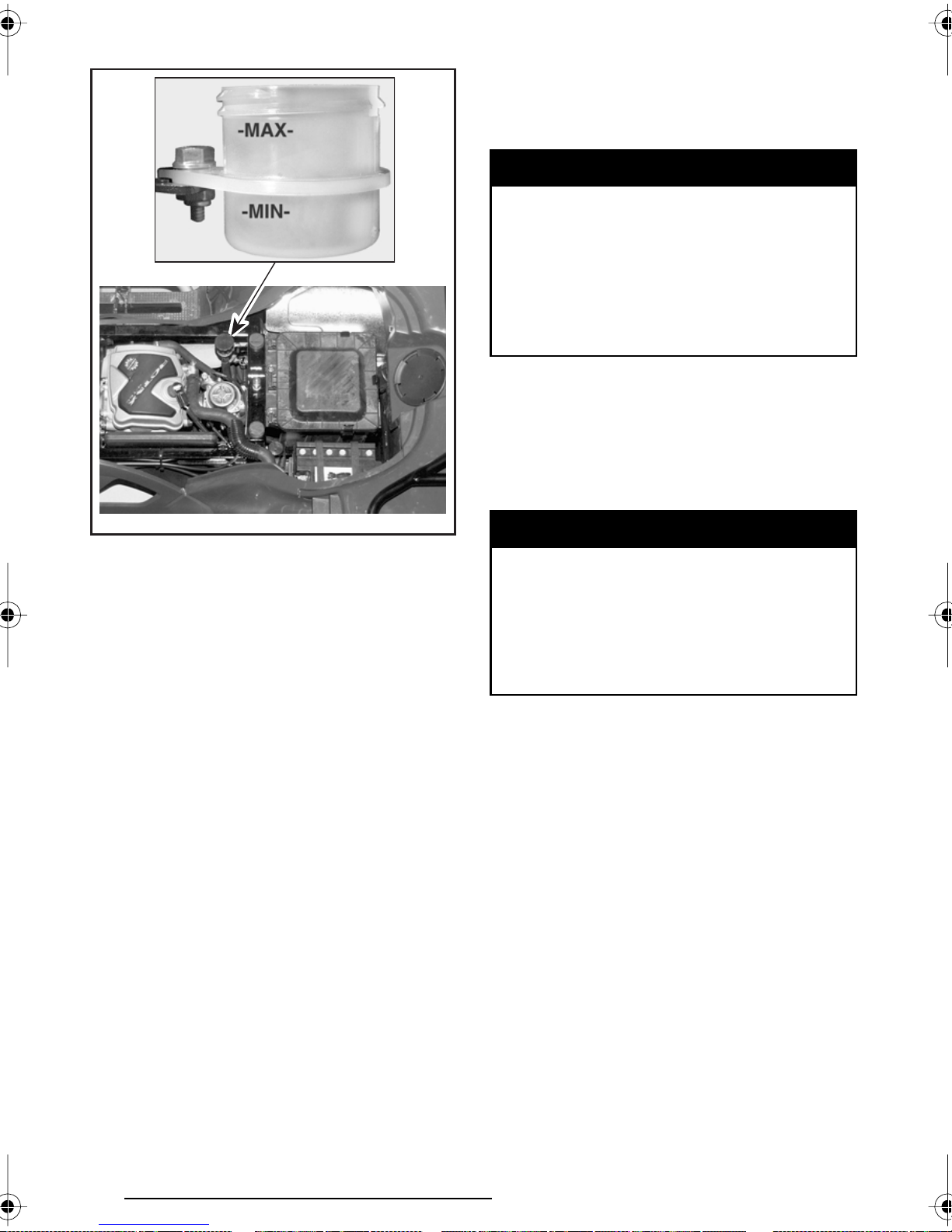
Rear Brake Fluid Reservoir
Battery
Removal
Disconnect negative BLACK cable first
then positive cable.
WARNING
Always respect this order for disassembly; disconnect BLACK negative cable first. Electrolyte or fuel
vapors can be present in engine
compartment and a spark may ignite them and possibly cause personal injuries.
Remove the holding straps.
Pull out vent tube from frame.
Remove battery from vehicle being
careful not to tilt it so that electrolyte
flows out of vent tube.
V04C06Y
Battery Electrolyte
Recommended Liquid
It is recommended to use distilled water.
Electrolyte Level
Place the vehicle on a level surface.
Check electrolyte level by the rear left
inner fender. Use a flashlight if necessary. Do not use an open flame.
The electrolyte should be between lower and upper marks. If level is low, remove battery from vehicle to add distilled water.
WARNING
Electrolyte is poisonous and dangerous. Avoid contact with eyes,
skin and clothing. Wear protective
eyeglasses and a suitable pair of
non-absorbent gloves when removing the battery by hand.
CAUTION: Should any electrolyte
spillage occur, immediately wash
off with a solution of baking soda
and water.
62
Page 65
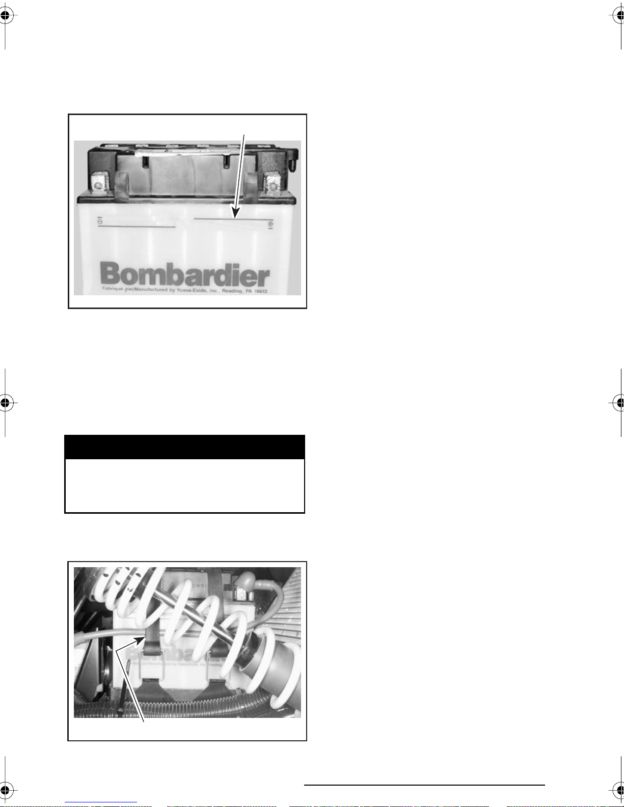
Refilling
Place battery on a level surface.
Unscrew caps and add distilled water
up to upper mark as required. Do not
overfill.
1
UPPER LEVEL/NIVEAU SUPÉRIEUR
V01G03Y
1. Upper mark
LOWER LEVEL/NIVEAU INFÉRIEUR
Properly retighten caps.
Installation
Reinstall battery in vehicle. Fasten battery and make sure to reinstall the vent
tube.
WARNING
Connect positive RED cable first
then negative cable. Always connect RED positive cable first.
NOTE: Place the positive RED cable
between holding straps and battery.
V01G05Y
1. Cable between battery and strap
1
63
Page 66

BREAK-IN PERIOD
Engine
A break-in period of 10 operating hours
is required before running the vehicle
at sustained full throttle.
CAUTION: Never mix oil with fuel.
This vehicle has a 4-stroke engine.
Oil must be added to engine base
only.
During this period, maximum throttle
should not exceed 3/4. However, brief
full acceleration and speed variations contribute to a good break-in.
Continued wide open throttle accelerations, prolonged cruising speeds and
engine overheating are detrimental
during the break-in period.
Belt
A new belt requires a break-in period of 30 miles (50 km). Avoid strong
acceleration/deceleration, pulling a
load or high speed cruising.
10-Hour Inspection
As with any precision piece of mechanical equipment, we suggest that
after the first 10 hours or 30 days after
the purchase, whichever comes first,
your vehicle be inspected by an authorized Bombardier ATV dealer. This inspection will give you the opportunity
to discuss the unanswered questions
you may have encountered during the
first hours of operation.
The 10-hour inspection is at the expense of the vehicle owner.
While reading this Operator’s Guide, remember that:
Indicates a potential hazard that could result in serious injury or death.
64
WARNING
Page 67

PRE-OPERATION CHECK
WARNING
• Ensure fuel valve is in fully open position (ON).
The pre-operation check is very
important prior to operating the
vehicle. Always check the proper
operation of critical controls, safety features and mechanical components before starting. If not
done as specified here, severe injury or death might occur.
• Check tire pressure and condition.
• Check wheels and bearings for wear
and damage.
• Check location of controls and ensure they work properly.
• Verify steering operates freely.
• Activate throttle control lever sever-
al times to ensure it operates freely.
It must return to idle position when
released.
• Activate the brake levers and foot
pedal to make sure the brakes fully
apply. Levers and pedal must fully
return when released.
• Ensure transmission lever is working then reset in PARK position.
• Check fuel, oil and coolant levels.
• Check for oil leaks on the engine/
transmission and drive train components.
• Clean headlights and taillight.
• Ensure front storage cover com-
partment is properly latched.
• Ensure seat is properly latched.
• If you transport cargo, respect load
capacity. Ensure cargo is properly
secured to the racks.
• If you are pulling a trailer or other
equipment, ensure it respects the
tongue capacity and towing capacity. Ensure trailer is properly secured
to hitch.
• Look and feel for loose parts while
engine is off. Check fasteners.
• Ensure the path of travel is free of
persons and obstacles.
• Check operation of ignition switch,
start button, engine stop switch,
headlights, dimmer switch, taillight
and indicator lights.
• Start engine and drive forward slowly a few feet and apply all brakes individually to test them.
Correct any problem you may have
found. See an authorized Bombardier ATV dealer as necessary.
65
Page 68
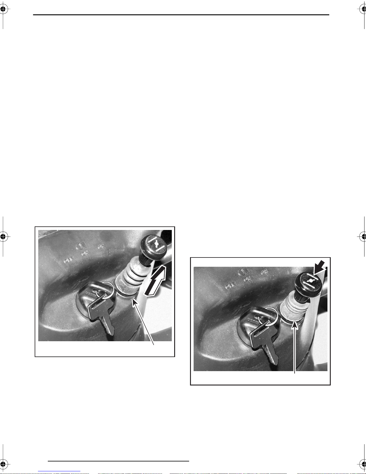
OPERATING INSTRUCTIONS
General
Transmission lever must be on PARK
or NEUTRAL to allow engine starting.
NOTE: For your convenience, an override mode allows the engine to be
started with the transmission lever in
any position. Press and hold the front
brake lever while pressing the start
button.
Place the engine stop switch to RUN
position then press start button.
Initial Cold Starting
Insert key in ignition switch and turn to
ON.
NOTE: Do not forget, place the engine
stop switch to RUN position.
In cold weather, colder than 0°C (32°F),
fully pull up the choke lever.
Press start button and hold until engine starts.
CAUTION: Do not hold start button
more than 30 seconds. A rest period
should be observed between the
cranking cycles to let starter cool
down. Pay attention not to discharge
battery.
NOTE: Throttle assist may be use to
help engine starting faster. Press the
throttle lever slightly. If too much throttle is used the choke system will not
be activated.
Release start button immediately when
engine has started.
After a few minutes, push in the choke
lever until the best engine RPM is
achieved.
NOTE: Overusing choke may flood engine and make it hard to start. Refer to
SPECIAL PROCEDURES if it occurs.
V01I18Z
1. Full choke position
When the engine is warm, push the
choke lever to OFF and release brakes.
1
V01I170
1. OFF position
1
66
Page 69

Warm Engine Starting
Apply the parking brake.
Start the engine as explained above
but without any choke. If the engine
will not start after two 5-second attempts with the electric starter, pull
the choke lever and place it half way
position. Start the engine without activating the throttle lever. After few seconds, push the choke lever to OFF.
Emergency Manual
Starting (if so equipped)
WARNING
Always place transmission lever
on PARK or NEUTRAL before starting engine manually.
Manual start is provided in the event
electric start does not work.
Set transmission lever in PARK position.
Push the engine stop switch in OFF
position.
Turn key in ignition switch to OFF.
Remove key from ignition switch.
Shifting the Transmission
Let engine idle to warm up.
Apply brakes and select the desired
gear range H/L.
NOTE: The brake must be applied when
the transmission lever is engaged in the
park position.
Release brakes.
CAUTION: Make sure parking brake
is fully disengaged before operating
the ATV.
Set transmission lever in PARK or NEUTRAL position. Apply parking brake
then turn the ignition key ON.
Grasp manual starter handle firmly
and, slowly, crank engine until a resistance appears.
Pass this resistance and release the
handle.
Take again the handle firmly and crank
engine.
Repeat this procedure completely if
necessary.
Stopping the Engine
WARNING
Avoid parking on an incline land.
Release throttle and completely stop
the vehicle.
Gradually press the throttle lever to increase engine speed and thus engaging the continuously variable transmission (CVT).
At the opposite, when the throttle lever is released, the engine speed decreases.
Using the Reverse
CAUTION: When changing from forward to reverse, or vice-versa, always completely stop the vehicle
and apply the brake prior to moving
the transmission lever.
The same procedures as Shifting the
Transmission above apply except for
the following.
Set the transmission lever in REVERSE
position.
67
Page 70
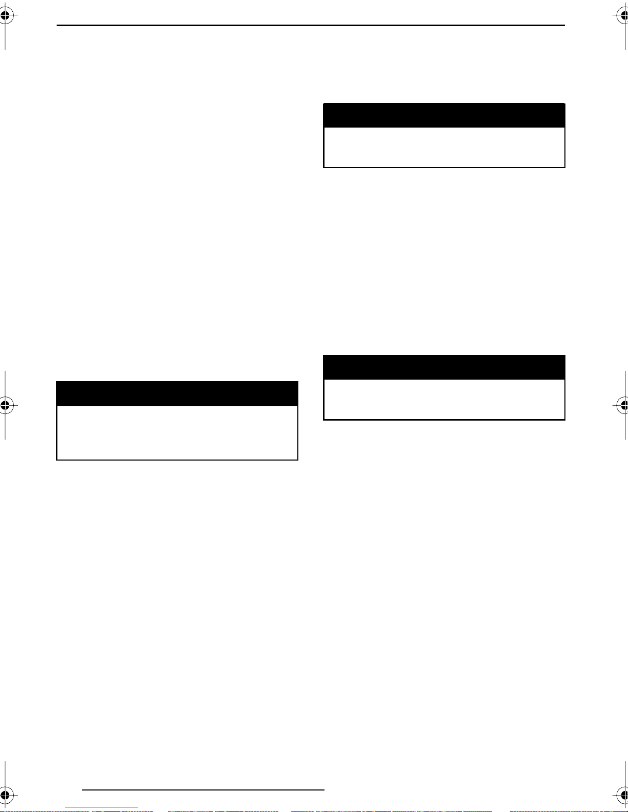
SPECIAL PROCEDURES
Flooded Engine
When the engine does not start after
several attempts, the engine may be
fuel flooded. Proceed as follows.
Turn ignition switch to ON and ensure
choke is not applied.
Ensure the transmission lever is on
PARK.
Fully press throttle lever and hold while
starting the engine.
As soon as the engine starts, release
throttle lever. Do not race engine.
If it does not work:
Disconnect the single-spark ignition
coil.
Clean the single-spark ignition coil area
then remove it. Remove the spark plug
(tools are supplied in tool box).
Check and clean radiator fins. See MAINTENANCE section.
WARNING
The radiator can be very hot, wear
gloves before touching radiator.
Reduce vehicle speed but try to keep
vehicle moving to supply air to radiator.
If engine is still overheating after approximately one minute, stop vehicle
and set transmission to PARK. Stop engine.
Place the ignition switch to ON position (Do not restart engine yet). The
radiator fan will cool the radiator.
Let engine cool down. Check coolant
level and refill if possible.
WARNING
WARNING
Always wear eye protector and
gloves when the spark plug hole
is cleaned.
Crank engine several times. Add a
small quantity of engine oil in cylinder
(equivalent to a cap of oil quart). Install
new spark plug if possible or clean and
dry spark plug.
Start engine as explained above. If engine continues to flood, see an authorized Bombardier ATV dealer.
Engine Overheat
If engine overheats and indicator light
turns on, try the following:
Ensure air ducts are not obstructed.
Never refill cooling system when
engine is hot.
See an authorized Bombardier ATV
dealer as soon as possible.
Post-Operation Care
When vehicle is used in salt-water environment (beach area, launching/
loading boats etc.), rinsing the vehicle
with fresh water is necessary to preserve vehicle and its components. Metallic parts lubrication is highly recommended. Use BOMBARDIER LUBE.
This must be performed at the end of
each operating day.
When vehicle is operated in muddy
conditions, rinsing the vehicle is recommended to preserve vehicle and its
components and to keep lights clean.
68
Page 71
Flipped Over
When vehicle is flipped over or stays
tilted on the side, wait 3 to 5 minutes
before starting engine. Check oil level
and refill if necessary. If the oil pressure light stays ON after starting engine, stop engine and see an authorized Bombardier ATV dealer as soon
as possible.
ATV Immersion
This performance-reduced mode allows the rider to go back home which
would not be possible without this advanced system. If this occurs, see an
authorized Bombardier ATV dealer as
soon as possible for inspection.
Storage and Preseason
Preparation
WARNING
Should the ATV become immersed, it
will be necessary to take it to an authorized Bombardier ATV dealer as soon
as possible. DO NOT START THE ENGINE! Immersion of the ATV can cause
serious damage if not correctly repaired.
Limp Home Mode
When low oil pressure is detected in
the engine, the engine RPM may be
reduced and not allowed to reach its
maximum RPM as usual. In this case,
letting the engine return to idle speed,
turning OFF the ignition key and restarting engine may allow normal operation.
Have an authorized Bombardier
ATV dealer inspects fuel system
integrity as specified in MAINTENANCE CHART.
When a vehicle is not in use for more
than one month, proper storage is a
necessity.
See an authorized Bombardier ATV
dealer for proper procedures.
When using your ATV after storage, a
preparation is required. See an authorized Bombardier ATV dealer for proper
procedures.
69
Page 72
MAINTENANCE CHART
The maintenance is very important, if you are not familiar with safe service practices and adjustment procedures, see your authorized Bombardier ATV dealer.
EVERY
LUBRICATION AND MAINTENANCE CHART
I: Inspect, verify, clean, adjust, lubricate, replace if necessary
C: Clean
L: Lubricate
R: Replace
ENGINE/TRANSMISSION
Engine/transmission oil and filter
Engine/transmission oil strainer cleaning C
Engine mount fasteners IIDEALER
Exhaust system II
Spark arrester C CUSTOMER
Condition of seals II
Coolant ➃ I
Radiator cap/cooling system pressure test II
Radiator condition/cleanliness (air ducts and radiator fins) ➂ II CUSTOMER
Drive belt I ➁
Cleaning/condition of drive and driven pulleys C
CVT air inlet duct condition/cleanliness and sealing II
Rewind starter rope condition (if so equipped) I
FUEL SYSTEM
Air filter
Fuel lines and connections II
Fuel tank strainer R
Carburetor II
ELECTRICAL SYSTEM
Spark plugs
Battery electrolyte level/connections/vent II
Wiring harnesses, cables and lines IIDEALER
Condition of ignition switch, start button and engine stop switch ➃ II
Condition of lighting system
(HI/LO intensity, brake light, headlight aiming, etc.)
Winch connections Refer to ATV Winch Operator’s Manual
DRIVE TRAIN
Drive shaft boot and protector
Drive shaft joint I DEALER
Front/Rear propeller shaft joint (grease fitting) IL
Wheel bearings condition I
Front differential and rear axle oil level, seals and vents IIRDEALER
STEERING/CONTROL SYSTEMS
Handlebar fasteners I
➃ C ➂ R ➂
➄
➃ RR
➃
➃
➀
INITIAL 10 h
INSPECTION
OR 185 mi (300 km)
25 h
OR 470 mi (750 km)
50 h
OR 930 mi (1500 km)
100 h OR 1 YEAR
OR 1865 mi (3000 km)
200 h OR 2 YEARS
➅
IR
II
II
R CUSTOMER
OR 3730 mi (6000 km)
CUSTOMER
CUSTOMER
DEALER
DEALER
DEALER
DEALER
DEALER
DEALER
DEALER
CUSTOMER
DEALER
DEALER
DEALER
DEALER
CUSTOMER
CUSTOMER
CUSTOMER
CUSTOMER
CUSTOMER
DEALER
DEALER
DEALER
TO BE
PERFORMED BY
70
Page 73

EVERY
LUBRICATION AND MAINTENANCE CHART
I: Inspect, verify, clean, adjust, lubricate, replace if necessary
C: Clean
L: Lubricate
R: Replace
Throttle/housing/cable ➃ II
Choke condition ➃ II
Steering system ➂ II
Tie rod end I
Wheel nuts/studs II
Wear/Pressure of tires ➃ II
Front wheel alignment II
SUSPENSION
Swing arm
Shock absorber ➃ I
A-arm I
BRAKE
Brake fluid front/rear
Brake cable II
Brake pad I
Brake system (discs, hoses etc.) I
BODY/FRAME
Engine compartment CC
Skid plates II
Frame I
Hitch/trailer ball condition (if installed) II
Chassis fasteners I
Front storage compartment cover/seat latches ➃ I
Vehicle cleaning and protection C
➃ I
➃ II R
➀
INITIAL 10 h
INSPECTION
OR 185 mi (300 km)
25 h
OR 470 mi (750 km)
50 h
OR 930 mi (1500 km)
100 h OR 1 YEAR
OR 1865 mi (3000 km)
200 h OR 2 YEARS
OR 3730 mi (6000 km)
CUSTOMER
CUSTOMER
DEALER
DEALER
CUSTOMER
CUSTOMER
DEALER
DEALER
DEALER
CUSTOMER
DEALER
DEALER
DEALER
DEALER
CUSTOMER
CUSTOMER
DEALER
CUSTOMER
CUSTOMER
CUSTOMER
CUSTOMER
TO BE
PERFORMED BY
➀ To be performed by an authorized Bombardier ATV dealer. The initial mainte-
nance is very important and must not be neglected.
➁ Measure and verify the drive belt. If the drive belt width is equal or less than
30 mm (1-3/16 in) or if flat spots, cracks or other damages are visible, replace
the drive belt.
➂ More often under severe use such dusty area, sand, snow, wet or muddy con-
ditions.
➃ Pre-ride inspection item.
➄ Make sure that the spark plug gap is correct.
➅ Every 100 hours, check coolant strength.
Refer to MAINTENANCE AND LUBRICATION section of Shop Manual for more
details.
71
Page 74

MAINTENANCE
While reading this Operator’s Guide, remember that:
WARNING
Indicates a potential hazard that could result in serious injury or death.
Place a drain pan under the engine drain
WARNING
plug area.
Unless otherwise specified, engine should not be running for all
maintenance procedures.
WARNING
Should removal of a locking device
(e.g. lock tabs, self-locking fasteners, etc.) be required when undergoing disassembly/assembly, always replace with a new one.
The following covers the maintenance
items that can be performed by the customer if desired. Other items found in
maintenance chart must be performed
by an authorized Bombardier ATV dealer.
NOTE: Among other things, this section gives the procedures to replace
the liquids. Refer to LIQUIDS for procedures to check levels and refill.
Engine/Transmission
Unscrew drain plug.
1
V04C07Y
1. Oil drain plug
Allow enough time for oil to flow out of
oil filter.
Unscrew the oil filter cover.
Oil Change and Oil Filter
Replacement
Oil and filter are to be replaced at the
same time. Oil change should be done
with a warm engine.
WARNING
The engine oil can be very hot.
Wait until engine oil is warm.
Ensure vehicle is on a level surface.
Clean the drain plug area.
Remove dipstick.
72
V04C08Y
Page 75

Remove the oil filter and replace with
a new filter.
NOTE: Check the cover O-ring and
change it if necessary.
Wipe out any oil spillage on engine.
Stop engine. Wait a while to allow oil
to flow down to crankcase then check
oil level. Refill as necessary.
Dispose of oil as per your local environmental regulations.
Remove skid plate.
Remove oil strainer cover and oil col-
lector, located near drain plug, then
clean oil strainer.
2
Coolant Replacement
WARNING
To prevent burning yourself, do
not remove the radiator cap or
loosen the engine drain plug if
the engine is hot.
Remove skid plate.
Turn the radiator cap counterclockwise
and remove it.
Unscrew the drain plug under oil filter
cover and drain the coolant into a suitable container.
V04C09Y
1. Oil strainer cover
2. Oil plug
To clean oil strainer, use a solvent then
dry with compressed air.
WARNING
Always wear eye protection and
gloves.
Reinstall oil strainer, oil collector and oil
strainer cover.
Change gasket on drain plug. Clean
gasket area on engine and drain plug
then reinstall plug. Refill engine at the
proper level with the recommended
oil. Refer to SPECIFICATIONS for capacity.
Start engine and let idle for a few minutes. Ensure oil filter area and drain
plug areas are not leaking.
1
V04C0AY
1. Cooling drain plug
NOTE: Do not unscrew the drain plug
completely.
1
73
Page 76

Unscrew the bleeding screw on the
top of thermostat housing.
V04C0BY
1
Install radiator cap. Inspect all connections for leaks and check coolant level
in the reservoir.
Valve Adjustment
Valve adjustment is not required on this
engine.
Spark Arrester
The muffler must be periodically purged
of accumulated carbon.
WARNING
1. Bleeding screw
Drain the system completely and reinstall the drain plug.
Pinch hose between radiator and thermostat housing with a large hose
pincher (P/N 529 032 500).
V04C0CY
Fill the radiator until the coolant comes
out by the thermostat housing hole. Install the bleeding screw then remove
the hose pincher.
Never run engine in an enclosed
area. Never perform this operation immediately after the engine
has been run because exhaust
system is very hot. Make sure that
there are no combustible materials in the area. Wear eye protection and gloves. Never stand behind the vehicle while purging
exhaust system. Respect all applicable laws and regulations.
Select a well-ventilated area and make
sure the muffler is cool.
Place transmission on PARK position.
Remove the clean-out plug from muffler.
Complete the radiator filling.
Check the level in the coolant reservoir
and refill if necessary.
Run engine at idle with the radiator cap
off. Slowly add additional coolant if
necessary.
At this point, wait until engine reaches
normal operating temperature. Depress the throttle lever two or three
times; then add coolant if required.
74
V04C0DY
TYPICAL
1. Clean-out plug
2. Muffler
12
Page 77

Block the end of muffler with a shop
rag and start engine.
WARNING
Momentarily increase engine RPM
several times to purge accumulated
carbon out of the muffler.
Stop engine and allow muffler to cool.
Reinstall the clean-out plug.
Radiator
Periodically check the radiator area and
the air ducts for cleanliness. Ensure air
ducts are unobstructed to allow air flow
going to the radiator.
An access hole is available to inspect
the radiator condition and to give access for cleaning.
Remove seat.
Pull on the circumference of the ac-
cess plug and remove plug.
Never clean radiator with your
hands when it is hot. Let the radiator cool down before cleaning.
CAUTION: Be careful not to damage
the radiator fins when cleaning. Do
not use any object/tool that could
damage the fins. The fins are purposely thin parts to allow efficient cooling.
WHEN HOSING, USE LOW PRESSURE ONLY.
Properly reinstall access plug and seat.
Air Intake System
Air Filter Cleaning/Draining
Periodically inspect air filter box drain
tube for water or deposits.
V01L2VY
1. Access plug
1
Inspect radiator fins. They must be
clean, free of mud, dirt, leaves and any
other deposit that would prevent the
radiator to cool properly.
Remove the deposits as much as you
can with your hands. If water is available in proximity, try rinsing the radiator fins.
If available, use a garden hose to rinse
the radiator fins.
V00A12Y
TYPICAL
1. Air filter box
2. Drain tube
3. Clamp
132
NOTE: If vehicle is used in dusty area,
inspect more frequently than specified
in MAINTENANCE CHART.
If water/deposits are found, squeeze and
remove the clamp. Pull drain tube out.
CAUTION: Do not start engine when
water is found in the drain tube.
When water/deposits are found, the air
filter must be inspected/dried/replaced
depending on its condition.
Remove air filter as explained below.
75
Page 78

Air Filter Removal
CAUTION: Never remove or modify
any component in the air box. The
engine carburetion is calibrated to
operate specifically with these components. Otherwise, engine performance degradation or damage can
occur.
Remove seat.
Release clamps and remove air filter
box cover.
1
2
Pour cleaning solution into a bucket,
dunk the filter multiple times until clean.
Rinse with warm water.
NOTE: Products like Simple Green,
dish soap or mild solvents can be used
to clean the air filter. Simple
Green
from Sunshine Makers Inc. is available
at hardware stores or at automotive
parts retailer.
While filter soaks, clean inside the air
box.
Then, let the filter dry completely.
When the filter is dried, re-oil with air
filter oil.
Air Filter Installation
Properly reinstall removed parts in the
reverse order of their removal.
®
V01F05Y
TYPICAL
1. Release clamps
2. Lift to remove
Loosen clamp and remove air filter.
1
2
Electrical
Battery
WARNING
Never charge a battery while installed in vehicle.
Clean battery post with a wire brush.
Apply dielectric grease on post to protect against oxidation.
Fuses
If a fuse is damaged, replace it by one
of the same rating.
CAUTION: Do not use a higher rated
fuse as this can cause severe damage.
Fuses are located on the RH side of
the rear of the vehicle, behind rear
bumper.
V01F1LY
1. Clamp
2. Air filter
76
Page 79

To remove fuse from holder, pull fuse
out. Check if filament is melted.
1
2
V04G01Y
1. Fuse block
1
Fuses are identified by a number located beside the fuse.
A15E0KY
1. Fuse
2. Check if melted
Bulb Replacement
Always check light operation after replacement.
Headlights
CAUTION: Never touch glass por-
tion of an halogen bulb with bare
fingers, it shortens its operating life.
If glass is touched, clean it with isopropyl alcohol which will not leave
a film on the bulb.
Unplug connector from headlight.
V00G01Y
1. Spare
2. Spare
3. Accessories (power outlet and auxiliary supply)
4. Fan
5. Main
6. Charging system
V04G02Y
77
Page 80
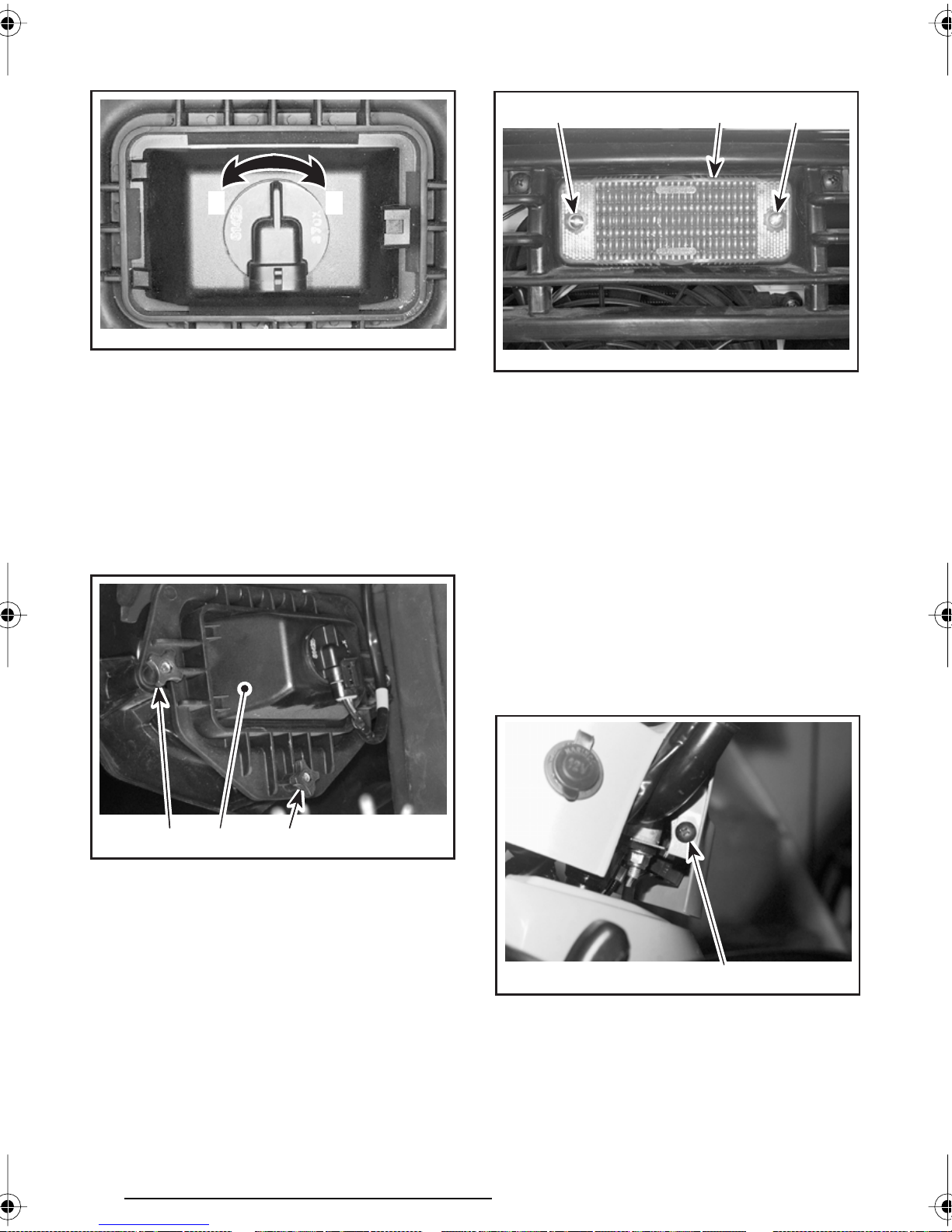
Rotate the bulb socket counterclockwise then remove headlight.
Install the new bulb by first pushing in
while turning clockwise.
1 2
V04G03Y
1. Unlock
2. Lock
Properly reinstall removed parts in the
reverse order of their removal.
Adjust beam aiming as follows:
Turn knobs to adjust beam height and
side orientation to your convenience.
Adjust both headlights evenly.
2
V01L0HY
1. Lens
2. Screws
12
Indicator Light Replacement
If one LED is burnt in the indicator light
cluster, see an authorized Bombardier
ATV dealer for replacement of the light
cluster.
V04G02Z
1. Headlight cover
2. Beam height adjustment
3. Beam side adjustment
3 2
1
Taillight Bulb Replacement
Unscrew lens screws to expose bulb.
Push bulb in and hold while turning
counterclockwise to release.
Speedometer Bulbs
Each bulb can be replaced individually.
Proceed as follows:
Remove the screw on each side of the
steering cover.
V00A13Y
1. One screw on each side
1
78
Page 81
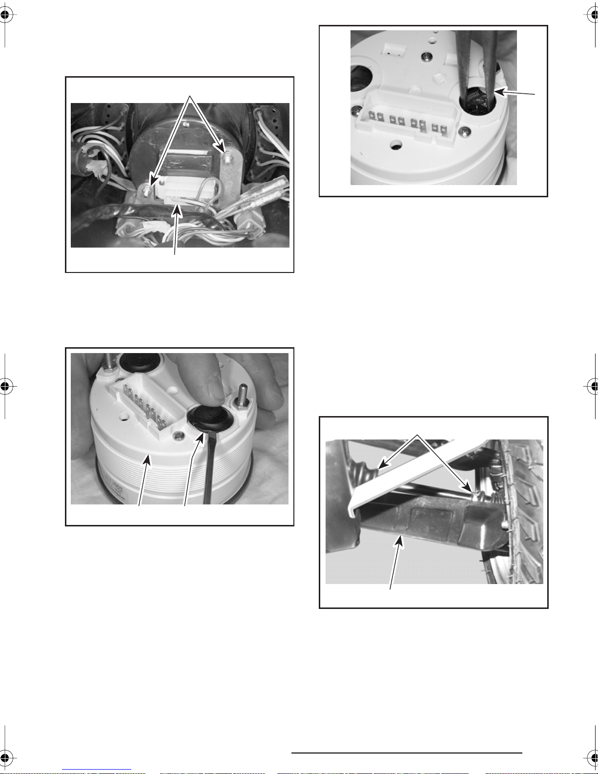
Pull up the steering cover.
Remove the two nuts under speedom-
eter and unplug the connector.
1
V01G06Y
1. Remove the two nuts
2. Unplug the connector
2
Using a small screwdriver, pry cap out
to expose bulb socket.
1
V01I0DY
1. Pull bulb out
Reinstall new bulb using long nose pliers. Turn bulb socket clockwise to lock.
Drive Train
Drive Shaft Boot/Protector
Inspection
Visually inspect drive shaft protectors
and boot conditions. Check protectors
for damage or rubbing against shafts.
Check boots for cracks, tears, leaking
grease etc. Repair or replace damaged
parts as necessary.
V01I0EY
1. Speedometer
2. Pry cap out
12
Insert a small screwdriver in socket slot
and turn counterclockwise until stopped.
Use small long nose pliers to pull bulb
out or carefully pry out using a small
screwdriver.
2
V00A14Y
1. Drive shaft protector
2. Drive shaft boots
1
79
Page 82
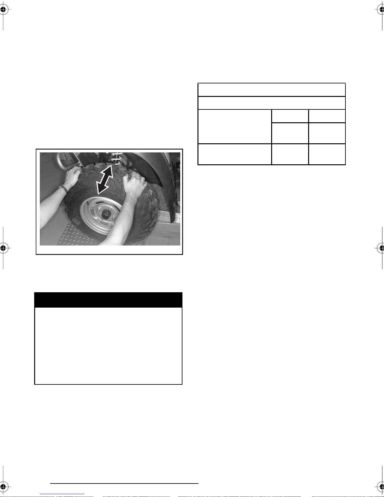
Wheel
Occasionally, wheel nuts should be removed to apply anti-seize lubricant on
studs to ease future removal. This is
particularly important when vehicle is
used in salt-water environment or in
mud. Remove one nut at a time, lubricate then retorque.
Check pressure when tires are “cold”
before using the vehicle. Tire pressure
changes with temperature and altitude. Recheck pressure if one of these
conditions has changed.
For your convenience, a pressure gauge
is supplied in tool box.
TIRE PRESSURE
Wheel Bearing Condition
Push and pull the wheels from the upper edge to feel the play. See an authorized Bombardier ATV dealer if there is
any play.
V01A0MY
Tires/Wheels
Tire Pressure
ALL MODELS
FRONT REAR
RECOMMENDED
MINIMUM
38 kPa
(5.5 PSI)
35 kPa
(5 PSI)
31 kPa
(4.5 PSI)
28 kPa
(4 PSI)
Although the tires are specifically designed for off-road use, a flat may still
occur. Therefore, it is recommended
to carry a tire pump and a repair kit.
Tire/Wheel Condition
Check tire for damage and wear. Replace if necessary.
Do not rotate tires. The front and rear
tires have a different size. The tires are
directional and their rotation must be
kept in a specific direction for proper
operation.
WARNING
Tire pressure greatly affects vehicle handling and stability. Underpressure may cause tire to deflate
and rotate on wheel. Overpressure may burst the tire. Always
follow recommended pressure.
Since tires are low-pressure types,
a manual pump should be used.
80
Wheel Removal
Loosen nuts then lift vehicle. Place a
support under vehicle. Remove nuts
then remove wheel.
At installation, it is recommended to
apply anti-seize lubricant on threads.
Gently tighten nuts in a criss-cross sequence then apply a final torque of
75 N•m (55 lbf•ft).
Page 83
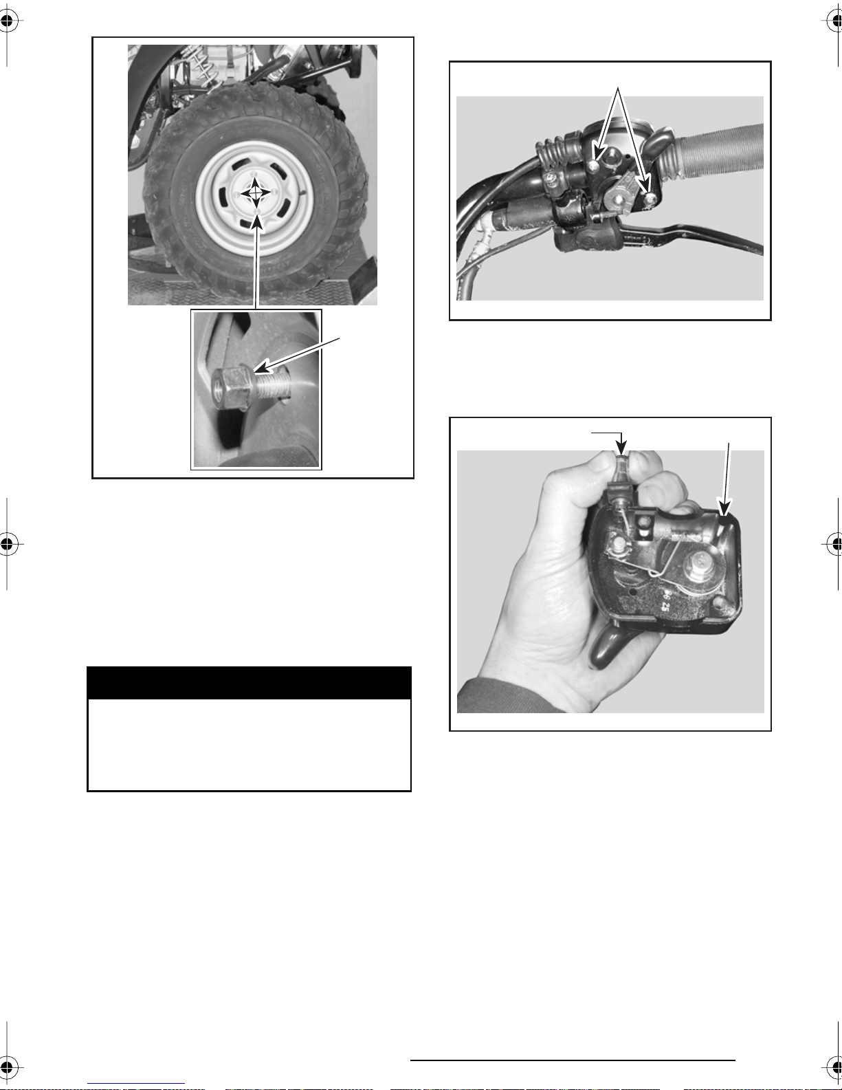
Open the throttle lever.
1
V01I0ZY
1
V01A08Y
1. Taper side of nut
Steering/Control Systems
Throttle Cable Lubrication
The throttle cable must be lubricated
with Bombardier cable lubricant (P/N
293 600 041) or an equivalent with the
same characteristics.
WARNING
Using another lubricant without
same characteristics could cause
the throttle lever/cable sticking or
stiffness.
1. Remove screws
Remove:
– the cable from the throttle lever
21
V01I10Y
1. Throttle handle housing
2. Throttle cable
NOTE: Slide cable in clip slot and remove the end of cable from clip.
81
Page 84
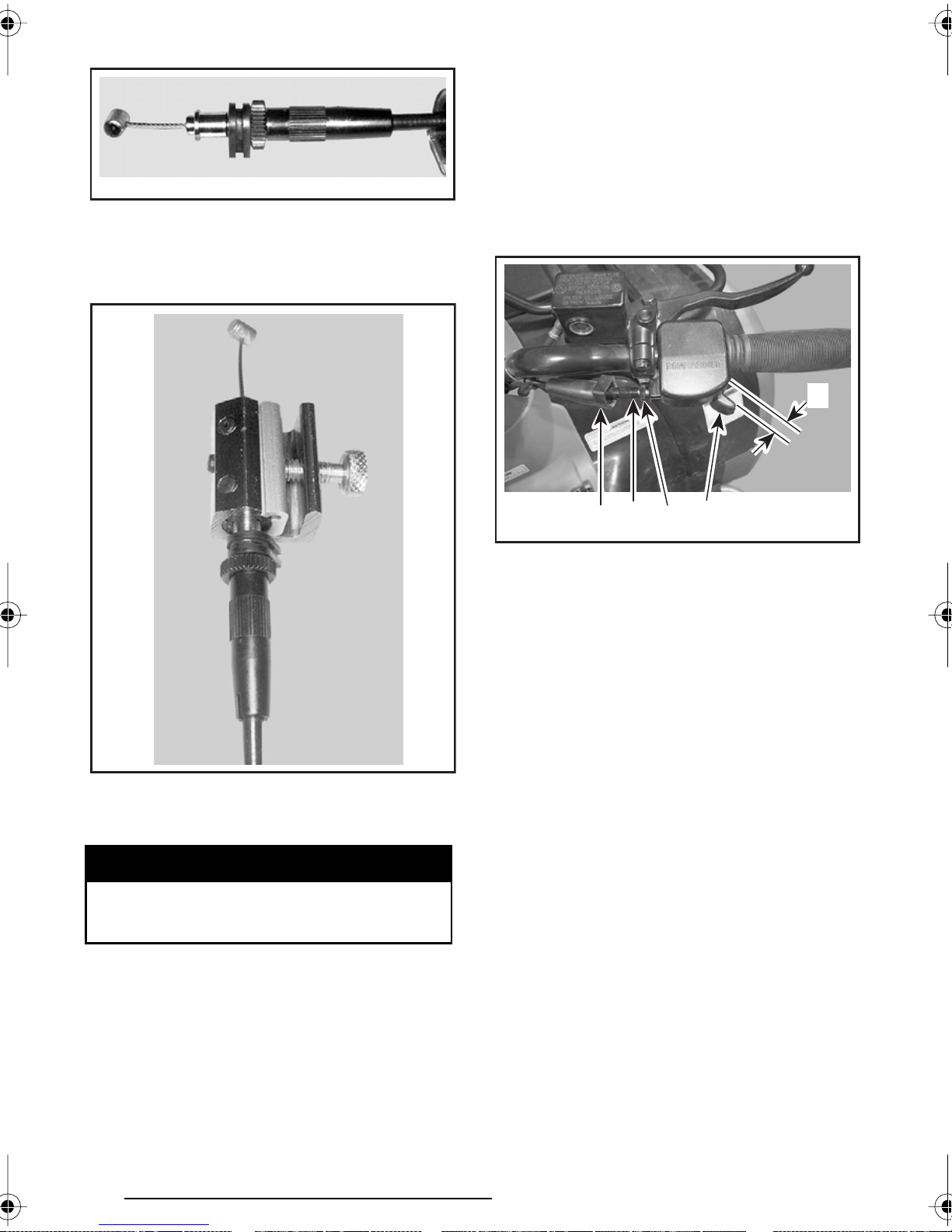
– the seal on the throttle cable.
Throttle Lever Adjustment
Slide rubber protector back to expose
throttle cable adjuster.
Loosen lock nut then turn the adjuster
to obtain correct throttle lever free play.
V00I02Y
Remove the carburetor side cover.
Install the cable luber (P/N 529 035 738)
on the cable.
NOTE: Measure throttle free play at
the tip of throttle lever.
Tighten lock nut and reinstall protector.
A
3
V04I02Y
1. Throttle lever
2. Protector
3. Cable adjuster
4. Lock nut
A. 3 to 6 mm (1/8 to 7/32 in)
2
1
4
V00I03Y
Insert the needle of lubricant can on
the cable luber hole.
WARNING
Always wear eye protection and
gloves when you lubricate a cable.
NOTE: Place a rag around the cable lu-
ber to prevent the lubricant splash.
Put the lubricant until it passes through
the cable.
Reinstall and adjust the cable.
Suspension
Lubrication
Lubricate front A-arms. Use synthetic
grease (P/N 293 550 010). There is two
grease fittings on the upper A-arm and
two on the lower A-arm (underneath).
82
Page 85
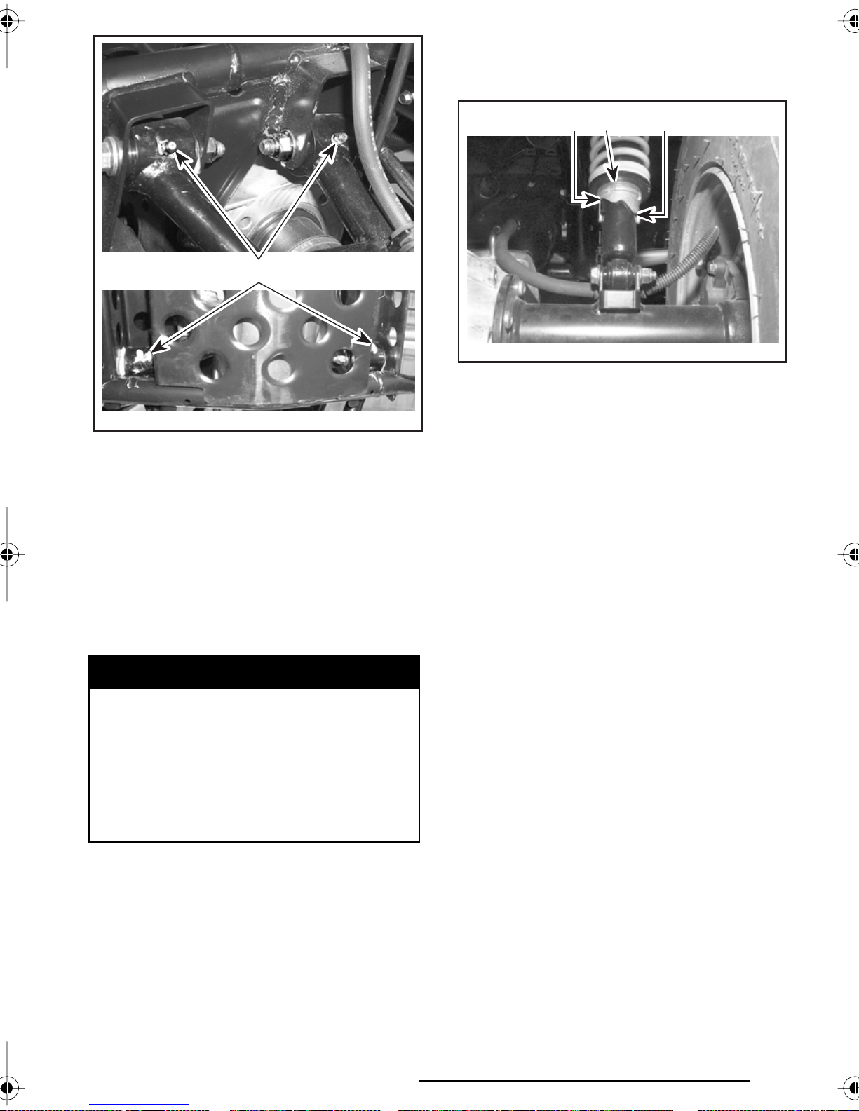
V01J0QY
Turn the adjusting cams counterclockwise for a light load and a smooth road
condition.
32 1
1
V01J0MY
1. Adjusting cams
2. Smooth adjustment
3. Hard adjustment
1. Grease fittings
Inspection
Inspect shock absorber for oil leaks
and fasteners for tightness. See an authorized Bombardier ATV dealer as
necessary.
Adjustment
Rear Shocks
WARNING
Left and right adjusting cams must
always be set at the same position. Never adjust one adjusting
cam only. Uneven adjustment
can cause poor handling and loss
of stability, which could lead to an
accident.
Preload Adjustment
Adjust spring preload by turning adjusting cam accordingly with the adjusting wrench in vehicle tool box.
Brake
Front Brake
The front brakes are hydraulic disc
types. These brakes are self-adjusting
and require no adjustment.
Rear Brake
The rear brake employs two systems.
The first system used a cable, an adjustment is necessary, see an authorized Bombardier ATV dealer. The second system is hydraulic and require no
adjustment. The systems are linked together for an higher efficiency.
Brake Cable Lubrication
Remove brake lever and lock (screw,
nut and spring).
Remove cable from hand lever. To ease
this operation, apply a force on the
brake pedal to loosen the cable.
Put the cable luber (P/N 529 035 738)
on the cable.
Turn the adjusting cams clockwise for a
firmer ride and rough road condition or
when carrying cargo or pulling a trailer.
Insert the needle of the spray can in
the hole.
83
Page 86

Spray a small quantity of silicone lubricant (P/N 293 600 041) then press the
brake pedal to move the brake cable.
Repeat this procedure until the silicone lubricant exits the other end of
the cable.
Body/Frame
Engine Compartment
Check engine compartment for any
damage and leaks. Ensure all hose
clamps are properly secured and no
hose is cracked, kinked or otherwise
damaged.
Inspect muffler, battery and reservoir
fastening devices.
Check electrical connections for corrosion and tightness.
Replace or have damaged parts repaired.
Skid Plate Condition
Check tightness of fasteners and condition of plate for cracks or other damage. Properly retighten fasteners as
necessary and have skid plate replaced
if damaged.
Hitch/Trailer Ball Condition
Fasteners
Check fastener condition and tightness
on the vehicle. Retighten as required.
Seat Latch
Remove seat and check latch mechanism and pin for wear. See an authorized Bombardier ATV dealer for parts
replacement if damaged.
Front Storage Compartment
Latch
Check latch condition. See an authorized Bombardier ATV dealer for parts
replacement if damaged.
Vehicle Cleaning and Protection
Painted parts which are damaged should
be properly repainted to prevent rust.
When required, wash the body with
hot water and soap (only use mild detergent). Apply non-abrasive wax.
CAUTION: Never clean plastic parts
with strong detergent, degreasing
agent, paint thinner, acetone, etc.
WHEN HOSING, USE LOW PRESSURE.
Check tightness of fasteners and
tightness/condition of trailer ball. Properly retighten as necessary and replace
ball if worn.
84
Page 87
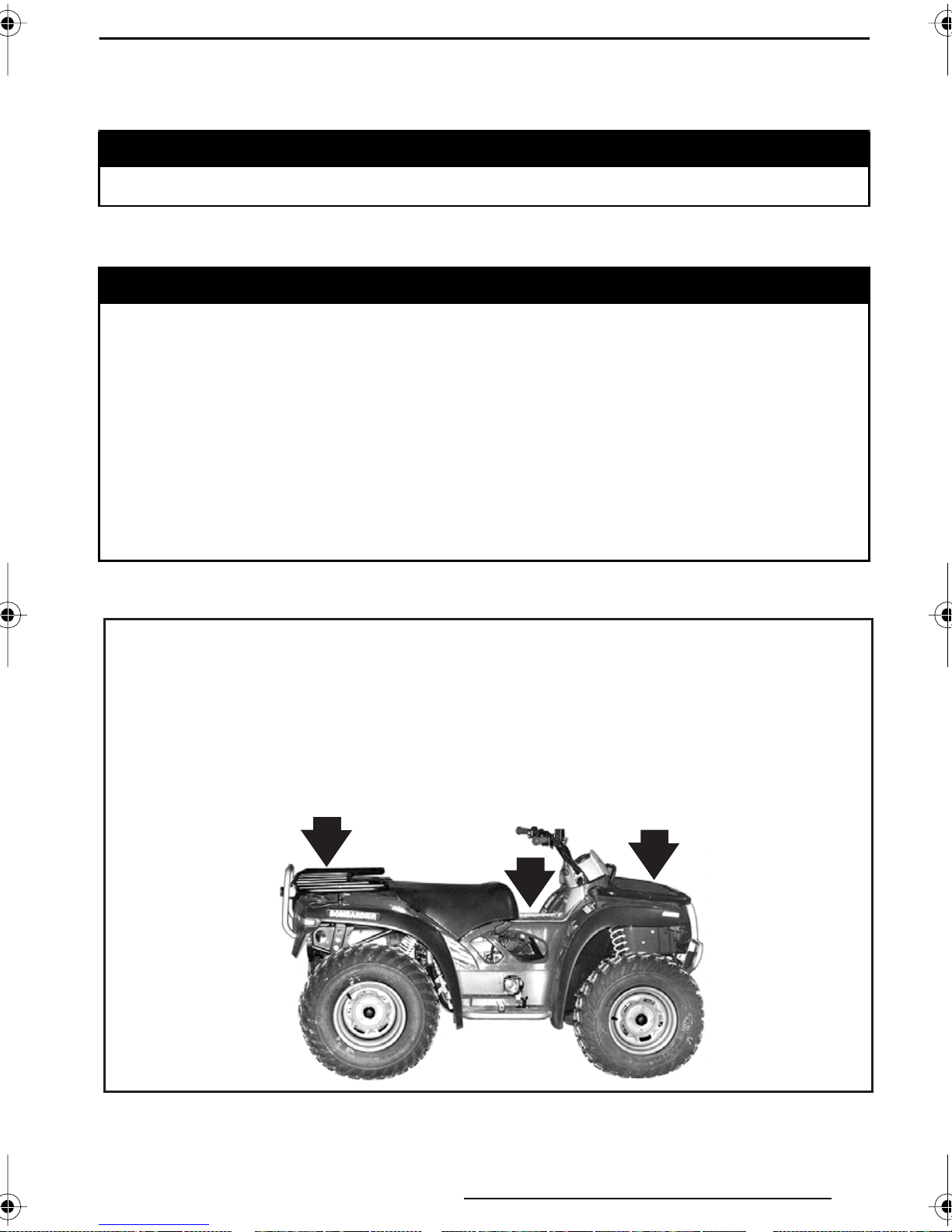
CARGO AND TRANSPORTATION
While reading this Operator’s Guide, remember that:
WARNING
Indicates a potential hazard that could result in serious injury or death.
Cargo
WARNING
The vehicle handling, stability and braking distance are affected when
loading racks and using the vehicle. Correct loading and weight distribution are therefore important. Never overload, tow or carry cargo improperly. Always ensure the cargo is safely secured and properly distributed
on the racks before operating the vehicle. Safely reduce speed according
to terrain conditions when carrying cargo or pulling a trailer. Allow greater
distance for breaking. Always secure cargo as low as possible on the racks
to reduce the effect of a higher center of gravity. Failure to follow the
recommendations here could cause changes in vehicle handling which
could lead to an accident resulting in severe injuries including the possibility of death. For more information, see the Safety Handbook.
When cargoing vehicle, respect these maximum loads.
TOTAL LOAD ALLOWED:
220 kg (485 lb)
(includes driver, all other loadsand added accessories)
80 kg (175 lb)
Includes rear
rack and
tongue load
5 kg (11 lb)
Console
maximal
load
40 kg (90 lb)
Includes front
rack and
storage
compartment
V04A01L
85
Page 88
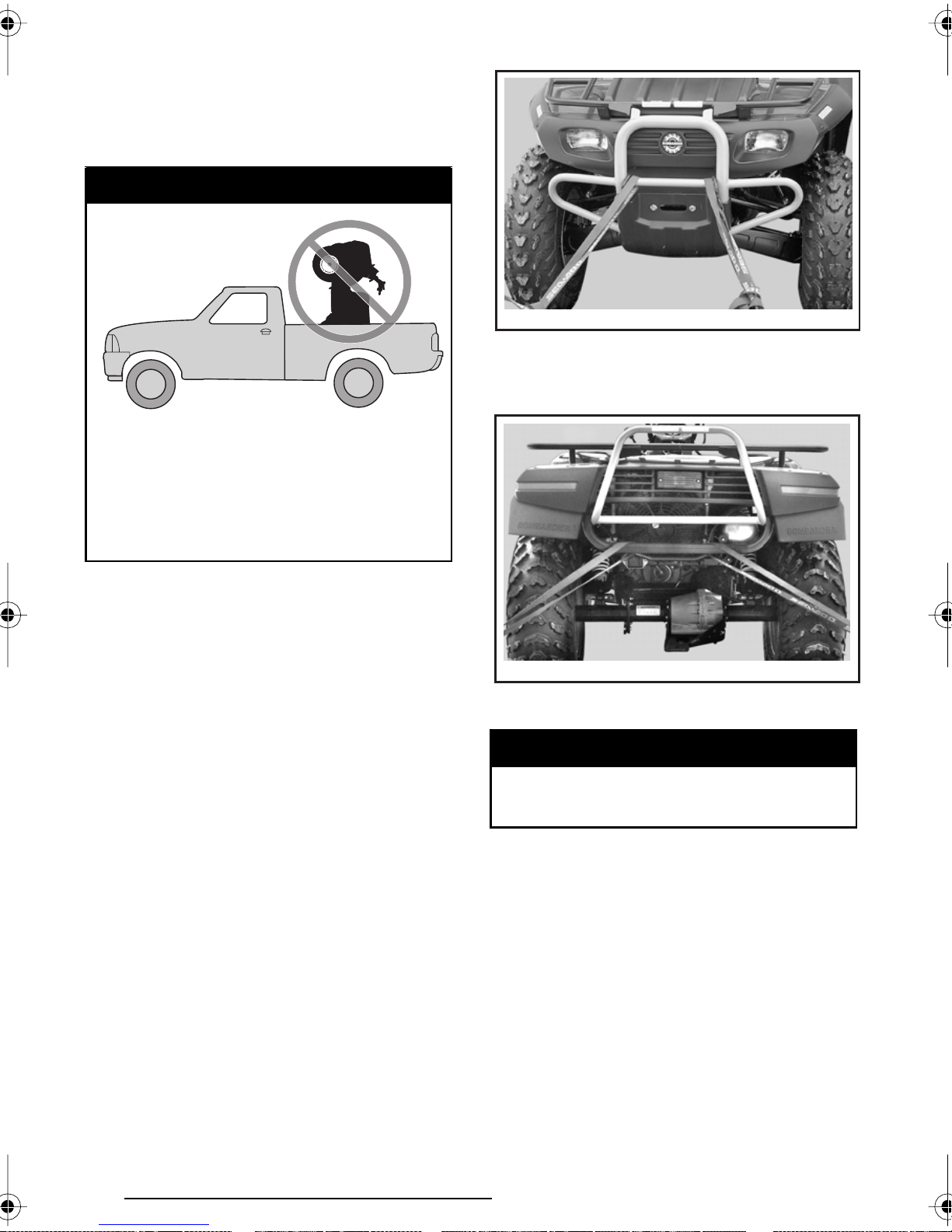
Transportation
When transporting a vehicle, secure
vehicle to trailer with suitable tiedowns. Using ordinary ropes is not recommended.
WARNING
V00A174
Never tip this vehicle on end for
transporting. We recommend
that you carry the vehicle in its
normal operating position (on all
four wheels).
Front Location
V00A15Y
TYPICAL
Rear Location
Place the fuel valve to OFF position.
Select the PARK position and set the
parking brake.
Secure the vehicle to front by the front
bumper and rear by the frame.
CAUTION: Attaching vehicle at other
locations may damage the vehicle.
V00A16Y
TYPICAL
WARNING
Do not tow this vehicle behind a
car or other vehicle.
86
Page 89

TROUBLESHOOTING
SYMPTOM: Engine does not turn
POSSIBLE CAUSES WHAT TO DO
1. Ignition switch is in the OFF po-
Place switch in the ON position.
sition.
2. Transmission is not set in the
PARK or NEUTRAL.
Set transmission either in PARK or in NEUTRAL or
use the override mode.
3. Burnt fuse. Check main supply fuse.
4. Weak battery or loose connections.
Check charging system fuse. Check connections
and terminals condition. Have the battery checked.
Contact an authorized Bombardier ATV dealer.
SYMPTOM: Engine turns over but fails to start
POSSIBLE CAUSES WHAT TO DO
1. Burnt fuse. Check ignition fuse condition.
2. Mixture not rich enough to start
cold engine.
3. Flooded engine
Check fuel tank level and check starting procedure,
particularly use of the choke.
Refer to SPECIAL PROCEDURES.
(spark plugs wet when removed).
4. No fuel to the engine
(spark plugs dry when removed).
Check fuel tank level; turn fuel valve to ON (also try
on RES). A failure of the fuel pump or carburetor
may have occurred. Contact an authorized Bombardier ATV dealer.
5. Spark plug/ignition (no spark). Check ignition fuse condition. Remove spark plug
then reconnect to single-spark ignition coil. Check
that ignition switch and/or engine stop switch(es)
is/are in the ON position. Start engine with spark
plug grounded to engine away from spark plug hole.
If no spark appears, replace spark plug. If trouble
persists, contact an authorized Bombardier ATV
dealer.
6. Engine compression. As the engine is pulled over with the rewind starter,
“cycles” of resistance should be felt as piston goes
past top dead center. If no pulsating resistance is
felt, it suggests a major loss of compression. Contact an authorized Bombardier ATV dealer.
7. Engine stop switch is in the
Place switch in the ON position.
OFF position.
87
Page 90

SYMPTOM: Engine lacks acceleration or power
POSSIBLE CAUSES WHAT TO DO
1. Fouled or damaged spark plug. Check item Engine turns over but fails to start.
2. Lack of fuel to engine. Check item Engine turns over but fails to start.
3. Carburetor adjustments. Contact an authorized Bombardier ATV dealer.
4. Engine is overheating. Check Engine Overheat in SPECIAL PROCE-
DURES. If overheating persists, contact an authorized Bombardier ATV dealer.
5. The LIMP HOME MODE is se-
lected.
Check sensors connectors.
Contact an authorized Bombardier ATV dealer.
6. Air box plugged or dirty Check air filter and clean if necessary.
Check the position of the air intake tube.
7. CVT dirty or wear. Contact an authorized Bombardier ATV dealer.
SYMPTOM: Engine backfire
POSSIBLE CAUSES WHAT TO DO
1. Exhaust system leakage. Contact an authorized Bombardier ATV dealer.
2. Engine is running too hot. See Engine lacks acceleration or power.
3. Ignition timing is incorrect or
Contact an authorized Bombardier ATV dealer.
there is an ignition system failure.
4. Improper carburetor setting. Contact an authorized Bombardier ATV dealer.
SYMPTOM: Engine misfire
POSSIBLE CAUSES WHAT TO DO
1. Fouled/damaged/worn spark plugs. Clean/verify spark plugs and heat range. Replace
as required.
2. Water in fuel. Drain fuel system and refill with fresh fuel.
SYMPTOM: Vehicle cannot reach full speed
POSSIBLE CAUSES WHAT TO DO
1. Engine. See Engine lacks acceleration or power.
2. Parking brake. Ensure brake lever lock is completely removed.
3. The LIMP HOME MODE is se-
lected.
4. Air box plugged or dirty Check air filter and clean if necessary.
5. CVT dirty or wear. Contact an authorized Bombardier ATV dealer.
88
Check sensors connectors.
Contact an authorized Bombardier ATV dealer.
Check the position of the air intake tube.
Page 91

SYMPTOM: Transmission lever is hard to move
POSSIBLE CAUSES WHAT TO DO
1. Transmission gears are in a position that prevents the transmission lever to work.
Rock the vehicle back and forth to move the gears
in the transmission and allow the transmission lever to be set.
2. Engine idle speed is set too high. Adjust the idle speed. Refer to the specification.
3. CVT dirty or wear. Contact an authorized Bombardier ATV dealer.
SYMPTOM: The RPM increases but the vehicle doesn’t move
POSSIBLE CAUSES WHAT TO DO
1. The transmission is in the P or N
position.
Put transmission lever on the HI, LOW or REVERSE position.
2. CVT is defective. Contact an authorized Bombardier ATV dealer.
3. Water in the CVT housing. a) Unscrew the drain plug of the CVT cover.
b) If the problem persists, contact an authorized
Bombardier ATV dealer.
89
Page 92

SPECIFICATIONS
VEHICLE MODEL QUEST 500
ENGINE
Type
Number of cylinder Single cylinder
Number of valve 4 valves with hydraulic lifters (no adjustment)
Displacement 498 cc (30.4 cu. in)
Bore Standard 100 mm (3.9 in)
Stroke 63.4 mm (2-1/2 in)
Compression ratio 10.5:1
Lubrication
Decompressor Automatic
Exhaust system
Air filter 2 stage foam filter
TRANSMISSION
Transmission Continuously Variable Transmission (CVT)
COOLING
BOMBARDIER-ROTAX 500 4-TEC 4 stroke.
Over Head Camshaft (OHC), liquid cooled
Wet sump with replaceable oil filter (lubrication
of engine and transmission simultaneously)
Spark arrester approved U.S.
Forest Service (USFD)
Type Liquid cooled
Radiator Rear mounted with thermostatic fan
CARBURETION
Carburetor make and type
Choke plunger position Variable
Idle speed ± 100 1100 RPM
Fuel pump make and type Mikuni, external (vacuum-operated)
Mikuni BSR42. Constant velocity with manual
choke and ECS (Enrichner Coasting System)
90
Page 93

VEHICLE MODEL QUEST 500
ELECTRICAL
Magneto generator make and type Denso, 400 W @ 6000 RPM
Ignition type CDI (Capacitor Discharge Ignition)
Ignition timing Not adjustable
Engine RPM limiter 7550 RPM (any gear in forward)
Vehicle speed limiter
15 km/h (9 MPH) in reverse
105 km/h (65 MPH) forward
Spark plug make and type NGK DCPR8E
Number of spark plug 1
Spark plug gap 0.7 mm (.027 in)
Battery 12 V, 19 A (20 A, optional). Electrolyte type battery
Starting system
Start on P, R, N, H or L position (with brake applied)
Electric start.
Headlight 2 x 30 W
Taillight 5/27 W
Pilot lamp cluster LEDS, 0.7 V approx. (each)
FUSES
Location no. 1 (empty) N.A.
Location no. 2 (empty) N.A.
Location no. 3 (accessories) 15 A (power outlet and auxiliary supply)
Location no. 4 (fan) 15 A
Location no. 5 (main) 20 A
Location no. 6 (charging system) 30 A
DRIVE TRAIN
Front differential
Shaft driven/single auto-lock differential
(shear pump)
Rear axle Shaft driven/solid axle
SUSPENSION
Type Independent suspension — double A-arm
Front
Travel 178 mm (7 in)
Type Rigid swing-arm
Rear
Travel 191 mm (7.5 in)
TIRES
Front
38 kPa (5.5 PSI) recommended,
35 kPa (5 PSI) minimum
Pressure
Rear
31 kPa (4.5 PSI) recommended,
28 kPa (4 PSI) minimum
Front 635 OD x 203 W x 305 ID mm (25 x 8 x 12 in)
Size
Rear 660 OD x 254 W x 305 ID mm (26 x 10 x 12 in)
91
Page 94

VEHICLE MODEL QUEST 500
WHEELS
Size
Front 305 dia. x 165 W mm (12 in x 6.5 in)
Rear 305 dia. x 203 W mm (12 in x 8 in)
Wheel nut torque 75 N•m (55 lbf•ft)
BRAKES
Front Hydraulic, 2 discs
Rear Hydraulic, 1 disc
Parking
Park through transmission.
LH brake lever includes a lock
LOADING CAPACITY
Front rack 40 kg (90 lb) includes front storage tray
Rear rack 80 kg (175 lb) includes tongue load
Console 5 kg (11 lb)
Total vehicle load allowed
220 kg (485 lb) includes driver,
all other loads and added accessories
GVWR (Gross Vehicle Weight Rating) 540 kg (1200 lb)
Towing capacity 500 kg (1100 lb)
Tongue capacity 14 kg (30 lb) included with rear rack
Front storage tray 10 kg (22 lb) included with front rack
DIMENSIONS
Dry mass 341 kg (753 lb)
Overall length 2071 mm (81.5 in)
Overall width 1194 mm (47 in)
Overall height 1143 mm (45 in)
Wheel base 1296 mm (51 in)
Front 992 mm (39 in)
Wheel track
Rear 940 mm (37 in)
Turning radius 2133.6 mm (84 in)
Toe-out adjustment
(each side)
Ground clearance
Front
Rear
Front and
under engine
8 mm ± 4 mm (5/16 in ± 5/32 in)
N.A.
244 mm (9.6 in)
Rear axle 188 mm (7.4 in)
Weight distribution (front/rear) 49/51%
92
Page 95

VEHICLE MODEL QUEST 500
LIQUIDS
SAE, 4-stroke mineral-based engine oil.
API classification SG, SH or SJ
Oil type (engine and transmission)
Coolant
Do not use synthetic oil or synthetic blend oil,
Refer to OIL VISCOSITY CHART for proper grade
or Bombardier synthetic oil.
other than Bombardier synthetic oil
Ethylene-glycol/water mix
(50% coolant, 50% water).
Use coolant specifically designed
for aluminum engines
Fuel
Differential Front and rear Synthetic polyolester oil 75W90 (API GL-5)
Hydraulic brake Brake fluid, DOT 4
Propeller shaft joint grease Shell, Alvania EP-2 only
CAPACITIES
Vehicle range
Fuel tank
Engine/transmission oil
Coolant 2.5 L (2.65 quarts)
Differential
OD = outside diameter
Type Regular unleaded gasoline
Octane 87 (R + M)/2 or higher
Approximately 10 hours depending
on many factors such as temperature,
operating conditions and load
22 L (5.8 U.S. gal) including approximately
4.25 L (1.1 U.S. gal) reserve
Oil change with filter: 2.5 L (2.65 quarts).
Total: 3.25 L (3.43 quarts)
Front 650 mL (22 U.S. oz)
Rear 200 mL (10 U.S. oz)
W = width
ID = inside diameter
dia. = diameter
Because of our ongoing commitment to product quality and innovation, Bombar-
dier reserves the right, at any time, to make changes in design and specifications
and/or to make additions to, or improvements in its products without imposing
any obligation upon itself to install them on its products previously manufactured.
OHV = overhead valve
LEDS = light-emitting diodes
93
Page 96
SI* METRIC INFORMATION GUIDE
SI* METRIC INFORMATION GUIDE
BASE UNITS
DESCRIPTION
length.................................................
mass ..................................................
force...................................................
liquid ..................................................
temperature .......................................
pressure .............................................
torque ................................................
land velocity .......................................
PREFIX
kilo ......................
centi ....................
milli......................
micro...................
TO CONVERT
in ........................................................
in ........................................................
in².......................................................
in³.......................................................
ft ........................................................
oz .......................................................
lb ........................................................
lbf .......................................................
lbf•in..................................................
lbf•ft...................................................
lbf•ft...................................................
PSI .....................................................
imp. oz ...............................................
imp. oz ...............................................
imp. gal ..............................................
imp. gal ..............................................
U.S. oz................................................
U.S. gal...............................................
MPH...................................................
Fahrenheit..........................................
Celsius ...............................................
hp.......................................................
SYMBOL
k .......................
c .......................
m ......................
µ .......................
CONVERSION FACTORS
UNIT
meter ................................
kilogram ............................
newton..............................
liter ....................................
Celsius ..............................
kilo pascal..........................
newton-meter ...................
kilometer per hour.............
PREFIXES
MEANING
one thousand ....................
one hundredth of ..............
one thousandth of.............
one millionth of .................
TO ➀
mm....................................
cm .....................................
cm²....................................
cm³....................................
m.......................................
g ........................................
kg ......................................
N .......................................
N•m ..................................
N•m ..................................
lbf•in.................................
kPa ....................................
U.S. oz...............................
mL.....................................
U.S. gal..............................
L ........................................
mL.....................................
L ........................................
km/h ..................................
Celsius ..............................
Fahrenheit .........................
kW.....................................
SYMBOL
m
kg
N
L
°C
kPa
N•m
km/h
VALUE
1000
0.01
0.001
0.000001
MULTIPLY BY
25.4
2.54
6.45
16.39
0.3
28.35
0.45
4.4
0.11
1.36
12
6.89
0.96
28.41
1.2
4.55
29.57
3.79
1.61
(°F - 32) ÷ 1.8
(°C x 1.8) + 32
.75
* The international system of units abbreviates SI in all languages.
➀ To obtain the reverse sequence, divide by the given factor. To convert milli-
meters to inches, divide by 25.4.
NOTE: Conversion factors are rounded off to 2 decimals for easier use.
94
Page 97

CHANGE OF ADDRESS
CHANGE OF ADDRESS
If your address has changed, be sure to fill out and mail the card provided on this
page.
Such notification is likewise necessary for your own safety even after expiration
of the original warranty, since Bombardier Inc. will be in a position to contact you
if correction to your ATV becomes necessary.
NOTE: This card is strictly for change of address only.
✃
CHANGE OF ADDRESS
VEHICLE IDENTIFICATION NUMBER
Model Number Vehicle Identification Number (V.I.N.)
OLD ADDRESS: ______________________________________________
NEW ADDRESS: ______________________________________________
❏
NAME
______________________________________________
NO. STREET APT
______________________________________________
CITY STATE/PROVINCE ZIP/POSTAL CODE
______________________________________________
COUNTRY
NAME
______________________________________________
NO. STREET APT
STOLEN UNITS
In the event that your ATV is stolen, you should notify your area’s distributor
warranty department of such.
Please provide your name, address, phone number, vehicle identification number and date it was stolen.
Bombardier will provide a list of stolen units to all ATV dealers on a monthly basis
to aid in recovery of such units to their owners.
______________________________________________
CITY STATE/PROVINCE ZIP/POSTAL CODE
______________________________________________
COUNTRY
95
Page 98
CHANGE OF ADDRESS
N
OTE: This card is strictly for change of address only.
CHANGE OF ADDRESS
✁
AFFIX
PROPER
POSTAGE
BOMBARDIER
RECREATIONAL PRODUCTS
WARRANTY DEPARTMENT
75, J.A. BOMBARDIER ST.
SHERBROOKE (QUEBEC)
CANADA J1L 1W3
Page 99
ATV MODEL No.
VEHICLE
IDENTIFICATION NUMBER (V.I.N.)
ENGINE
IDENTIFICATION NUMBER (E.I.N.)
Owner:
No. STREET APT
CITY STATE/PROVINCE ZIP/POSTAL CODE
Purchase Date
Warranty Expiry Date
To be completed by the dealer at the time of the sale.
NAME
YEAR MONTH DAY
YEAR MONTH DAY
DEALER IMPRINT AREA
Please verify with your selling dealer to ensure your ATV has been registered with Bombardier.
Page 100
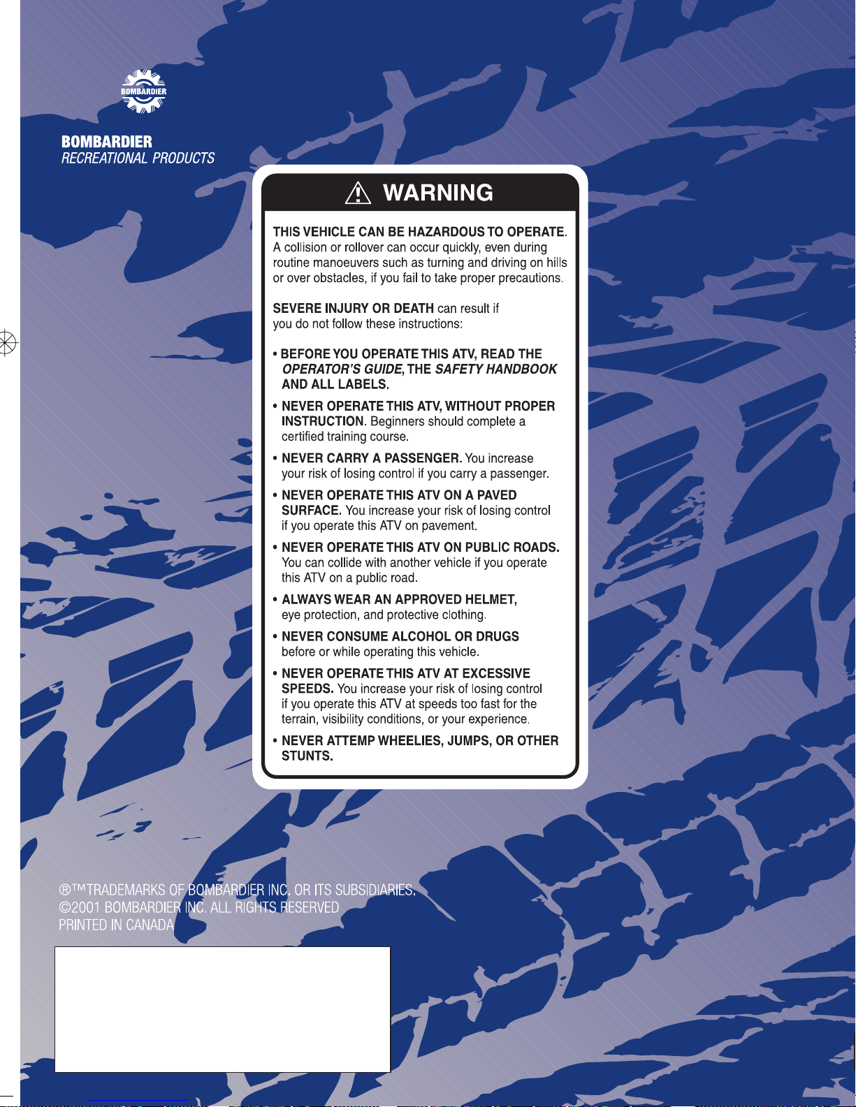
 Loading...