

Bombardier 462-532-582UL Repair Manual

Repair
HISTORICAL DOCUMENTS - FOR EDUCATIONAL PURPOSES ONLY (ENGINES NO LONGER IN PRODUCTION: Information May Be Outdated)
Manual
for engine type
462 - 532 - 582 UL
Edition: 10 1994
Bombardier-Rotax GmbH
4623 GUNSKIRCHEN Telefon: (0)7246/271-0*
Welser Strasse 32 Telefax: (0)7246/370
recommended ATS 900,-price:
WITHOUT COMMITMENT TO ADVISE MODIFICATIONS.
FOR INFORMATION ONLY.
Part no: 899 081

Table of contents
HISTORICAL DOCUMENTS - FOR EDUCATIONAL PURPOSES ONLY (ENGINES NO LONGER IN PRODUCTION: Information May Be Outdated)
1) Introduction:.................................................................................................................. 6
1.1) Engine number: .............................................................................................................................6
1.2) General notes: ...............................................................................................................................7
2) Technical data: .............................................................................................................8
2.1) Technical data ROTAX engine type 462 UL: ..............................................................................8
2.2) Technical data ROTAX engine type 532 UL: ............................................................................10
2.3) Technical data ROTAX engine type 582 UL: ............................................................................12
3) Tools and supplementary means: ........................................................................... 15
3.1) Standard tools: ............................................................................................................................15
3.2) Special service tools for the engine: ........................................................................................16
3.3) Special service tools and gasket set for reduction gearbox "A" and "B": ...........................19
3.4) Special service tools and gasket set for the reduction gearbox "C": ...................................20
3.5) Lubricating-, securing- and sealing agents: ............................................................................21
4) Powerplant in aircraft: ............................................................................................... 22
4.1) Removal of engine from the aircraft: ........................................................................................22
4.2) Re-installation of engine into aircraft: ......................................................................................22
5) Disassembly of engine:.............................................................................................23
5.1) Removal of reduction gearbox „A“: ..........................................................................................23
5.2) Removal of reduction gearbox „B“: ..........................................................................................24
5.3) Disassembly of reduction gearbox „C“:...................................................................................25
5.4) Removal of rewind starter:.........................................................................................................27
5.5) Dismantling of electric starter: ..................................................................................................27
5.6) Removal of exhaust manifold: ...................................................................................................28
5.7) Removal of ignition coils support plate and disassembly of rotary disk: ...........................28
5.7.1) Engine type 462 UL: .......................................................................................................28
5.7.2) Engine type 532 and 582 UL: .........................................................................................29
5.8) Disassembly of water pump: .....................................................................................................31
5.9) Disassembly of rotary valve shaft:............................................................................................31
5.10) Disassembly of BOSCH ignition unit:.......................................................................................32
5.11) Disassembly of DUCATI ignition unit: ......................................................................................33
5.12) Removal of cylinder head (type 462): .......................................................................................34
5.13) Removal of cylinder head (type 532 and 582): .........................................................................35
5.14) Disassembly of cylinders and pistons: ....................................................................................35
5.15) Disassembly of crankcase: ........................................................................................................37
6) Cleaning of engine components:............................................................................. 38
7) Inspection and judgement of components: ........................................................... 39
7.1) Crankcase: ...................................................................................................................................39
7.1.1) Measuring of crankcase:.................................................................................................39
7.2) Crankshaft:...................................................................................................................................41
7.2.1) Removal and inspection of crankshaft bearings:............................................................41
7.2.2) Checking of crankshaft alignment:..................................................................................42
7.2.3) Radial- and axial clearance of conrod: ...........................................................................43
7.3) Cylinder: .......................................................................................................................................45
7.3.1) Inspection of the cylinder: ...............................................................................................45
7.3.2) Cylinder bore:..................................................................................................................46
7.4) Piston: ..........................................................................................................................................47
7.4.1) Piston-to-wall clearance:.................................................................................................47
7.4.2) Piston rings: ....................................................................................................................48
7.4.3) Piston pin: .......................................................................................................................49
7.4.4) Piston pin bearing: ..........................................................................................................49
7.5) Cylinder head: .............................................................................................................................50
7.6) Thermostat:..................................................................................................................................50
- 2 - of 170
Rm. 462-532-582 UL10-1994

7.7) Rotary valve shaft: ......................................................................................................................51
HISTORICAL DOCUMENTS - FOR EDUCATIONAL PURPOSES ONLY (ENGINES NO LONGER IN PRODUCTION: Information May Be Outdated)
7.7.1) Disassembly of rotary valve shaft: ..................................................................................51
7.7.2) Inspection of the single components: .............................................................................52
7.7.3) Sealing of rotary valve shaft: ..........................................................................................52
7.7.4) Reassembly of rotary valve shaft:...................................................................................53
7.8) Contact breaker ignition unit: ....................................................................................................54
7.8.1) BOSCH magneto generator SCP2 on ROTAX 462 UL and 532 UL: .............................54
7.8.2) Stator plate:.....................................................................................................................54
7.8.3) Wiring diagram: ...............................................................................................................55
7.8.4) Flywheel: .........................................................................................................................55
7.8.5) Ignition damping box:......................................................................................................56
7.8.6) Adjusting of ignition timing: .............................................................................................57
7.8.7) Pole shoe breakaway gap:..............................................................................................58
7.9) ROTAX 582 UL with breakerless DUCATI dual ignition unit (DCDI): .....................................59
7.9.1) Brief description: .............................................................................................................59
7.9.2) Operation of the ignition unit:..........................................................................................59
7.9.3) Ignition switches:.............................................................................................................59
7.9.4) Magneto flywheel: ...........................................................................................................60
7.9.5) Electronic box:.................................................................................................................60
7.9.6) Wiring diagram of electronic box: ...................................................................................61
7.9.7) Wiring diagram: ...............................................................................................................62
7.9.8) Stator repair kit:...............................................................................................................63
7.9.9) Trouble shooting: ............................................................................................................63
7.9.10) Fault-tracing schedule:....................................................................................................64
7.9.11) Resistance values of DUCATI ignition unit: ....................................................................64
7.9.12) Sundry data of DUCATI ignition system: ........................................................................64
7.10) Spark plugs:.................................................................................................................................65
7.11) Spark plug connector: ................................................................................................................67
7.12) Hydro-damper:.............................................................................................................................67
7.13) Rewind starter: ............................................................................................................................68
7.13.1) Disassembly of rewind starter:........................................................................................68
7.13.2) Reassembly of rewind starter: ........................................................................................69
7.14) Electric starter: ............................................................................................................................71
7.14.1) Pinion starter on P.T.O. side: ..........................................................................................71
7.14.2) Pinion starter on magneto side: ......................................................................................71
7.14.3) Check of electric starter: .................................................................................................72
7.15) Carburetor:...................................................................................................................................74
7.15.1) Attachment: .....................................................................................................................75
7.15.2) Fuel intake control:..........................................................................................................75
7.15.3) Main regulating system: ..................................................................................................76
7.15.4) Sectional view of Bing-double float carburetor: ..............................................................77
7.15.5) Idling system: ..................................................................................................................79
7.15.6) Starting aid (starting carburator): ....................................................................................80
7.15.7) Check list for carburetor: .................................................................................................80
7.16) Pneumatic synchronization of a 2-carb installation:...............................................................81
7.16.1) Mechanical synchronization: ...........................................................................................82
7.17) Matching of the carburetor to specific climatic conditions: ..................................................82
7.18) Rubber carburetor-adaptor: .......................................................................................................83
7.19) Air filter:........................................................................................................................................84
7.19.1) Application of new air filters: ...........................................................................................84
7.19.2) Cleaning of used air filters: .............................................................................................85
7.20) Intake silencer: ............................................................................................................................85
7.21) Fuel pressure testing:.................................................................................................................87
7.21.1) Fitting the fuel pressure tester: .......................................................................................87
7.21.2) Test procedure: ...............................................................................................................88
7.21.3) Fault finding:....................................................................................................................88
Rm. 462-532-582 UL 10-1994
- 3 - of 170

7.22) Cooling system of engine: .........................................................................................................91
HISTORICAL DOCUMENTS - FOR EDUCATIONAL PURPOSES ONLY (ENGINES NO LONGER IN PRODUCTION: Information May Be Outdated)
7.22.1) Venting of the cylinder head: ..........................................................................................91
7.22.2) Operation of radiator cap and overflow bottle:................................................................92
7.22.3) Temperature of coolant: ..................................................................................................92
7.22.4) Checking of the single components: ...............................................................................93
7.22.5) Flowrate of coolant:.........................................................................................................93
7.22.6) Cooling circuit for engine installation with spark plugs up: .............................................94
7.22.7) Cooling circuit for engine installation with spark plugs down: ........................................95
7.23) Oil circuit for rotary valve- and water pump drive:..................................................................96
7.23.1) Oil circuit for engine installation with spark plugs “up”: ..................................................97
7.23.2) Oil circuit for engine installation with spark plugs “down":..............................................97
7.24) Oil pump for fresh oil engine lubrication (ROTAX 582 DCDI): ...............................................98
7.24.1) Description: .....................................................................................................................98
7.24.2) Technical data, characteristics: ......................................................................................98
7.24.3) Installation: ......................................................................................................................98
7.24.4) Disassembly of oil pump: ................................................................................................99
7.24.5) Adjustment on oil pump installation: .............................................................................100
7.24.6) Maintenance:.................................................................................................................100
7.24.7) Directions for installation: ..............................................................................................101
7.25) Exhaust system:........................................................................................................................102
7.25.1) Installation of the exhaust system:................................................................................103
7.25.2) After-muffler system: .....................................................................................................103
7.26) Propeller reduction gears type “A” and “B”: .........................................................................104
7.26.1) General information: .....................................................................................................104
7.26.2) Moment of inertia: .........................................................................................................104
7.26.3) Fitting position of powerplant: .......................................................................................105
7.26.4) Reduction gear type “A”: ...............................................................................................106
7.26.5) Reduction gear type “B”: ...............................................................................................107
7.26.6) Disassembly and judgement (reduction gears “A” and “B”): .......................................108
7.26.7) Reassembly of propeller reduction gear (type “A” and “B”): .........................................109
7.26.8) Determination of the proper preload setting of the springs (type “A” and “B”): ............110
7.26.9) Fitting of gear to engine (type “A” and “B”): ..................................................................111
7.27) Reduction gear type “C”: ............................................................................................................113
7.27.1) General information: .....................................................................................................113
7.27.2) Disassembly of gear cover:...........................................................................................113
7.27.3) Reassembly of gear cover: ...........................................................................................114
7.27.4) Inspection of gear housing and reassembly: ................................................................115
7.27.5) Adjusting axial clearance on reduction gear “C”: ..........................................................116
7.27.6) Assembly of reduction gear Type “C”: ..........................................................................117
7.28) General notes and maintenance of reduction gear:..............................................................119
8) Assembly of the engine: .......................................................................................... 120
8.1) Crankshaft:.................................................................................................................................120
8.2) Crankcase: .................................................................................................................................123
8.3) Assembly of the rotary valve shaft: ........................................................................................126
8.4) Assembly of the water pump: ..................................................................................................127
8.5) Fitting of the pistons:................................................................................................................127
8.5.1) Assembly of piston on Type 532 and 582 UL:..............................................................129
8.6) Re-assembly of the cylinders: .................................................................................................130
8.7) Assembly of the cylinder head: ...............................................................................................132
8.8) Fitting and setting of rotary valve: ..........................................................................................134
8.8.1) Rotary valve timing: ......................................................................................................135
8.7.2) Fitting of the rotary valve cover:....................................................................................135
- 4 - of 170
Rm. 462-532-582 UL10-1994

8.9) Installation of the ignition unit:................................................................................................136
HISTORICAL DOCUMENTS - FOR EDUCATIONAL PURPOSES ONLY (ENGINES NO LONGER IN PRODUCTION: Information May Be Outdated)
8.9.1) Fitting of stator plate assembly on engines 462 UL and 532 UL:.................................136
8.9.2) Ignition timing: ...............................................................................................................136
8.9.3) Adjustment of ignition timing:........................................................................................136
8.9.4) Break-away gap: ...........................................................................................................136
8.9.5) Fitting of the stator plate assembly on Type 582 UL: ...................................................137
8.9.6) Adjustment of trigger gap:.............................................................................................138
8.9.7) Setting of the ignition timing..........................................................................................139
8.10) Fitting of the rewind starter: ....................................................................................................140
8.11) Fitting of the electric starter: ...................................................................................................140
8.11.1) Electric starter on p.t.o. side: ........................................................................................140
8.11.2) Electric starter on magneto side: ..................................................................................141
8.11.3) Power supply to electric starter:....................................................................................141
8.12) Installation of the thermostat:..................................................................................................141
8.13) Fitting and assembly of ignition components supporting plate:.........................................142
8.14) Installation of the oil tank:........................................................................................................144
8.15) Installation of propeller reduction gear: .................................................................................144
8.16) Fitting of the exhaust manifold:...............................................................................................144
8.17) Fitting of the carburetors: ........................................................................................................145
8.17.1) Carburetor air intake: ....................................................................................................146
9) Trouble shooting:.....................................................................................................147
10) Extract from an article about power plants of UL aircraft by an expert:.........150
10.1) Carburetor icing: .......................................................................................................................150
10.2) Fuel systems: ............................................................................................................................151
10.2.1) Check the spark plug(s): ...............................................................................................151
10.2.2) Check engine for seizure: .............................................................................................152
10.2.3) Inspection of the fuel system: .......................................................................................152
10.2.4) Examination of fuel line between tank and fuel pump: .................................................152
10.2.5) Elimination of air leaks in the fuel line: .........................................................................154
10.2.6) Fuel supply to float chamber:........................................................................................154
10.2.7) Float chamber and main jet: .........................................................................................155
10.2.8) Problems related to fuel supply: ...................................................................................155
10.2.9) Various effects on formation of the air/fuel mixture: .....................................................156
10.3) Ignition problems: .....................................................................................................................157
10.4) Propeller matching:...................................................................................................................157
10.5) Prevention is better than cure: ................................................................................................158
11) Epilogue:....................................................................................................................158
12) Maintenance plan .....................................................................................................159
13) Essential tightening torques for engine types 462 - 532 - 582 UL: ..................160
14) Table of wear limits:................................................................................................. 162
15) Operational limits:....................................................................................................164
16) Operating liquids: ..................................................................................................... 164
17) AUTHORIZED DISTRIBUTORS and SERVICE CENTERS................................165
18) Modifications: ........................................................................................................... 169
Rm. 462-532-582 UL 10-1994
- 5 - of 170

1) Introduction:
HISTORICAL DOCUMENTS - FOR EDUCATIONAL PURPOSES ONLY (ENGINES NO LONGER IN PRODUCTION: Information May Be Outdated)
This Repair Manual covers the ROTAX 2-cycle-, 2-cylinder-, water-cooled ULTRALIGHT
AIRCRAFT ENGINES, Type 462, 532 and 582 UL. The manual has been prepared as a guide
to help to service and repair these engines correctly. It is supplemented by the corresponding
Operator’s Manual and a current Spare Parts List.
For installing the engine into the aircraft, consult the Installation Instructions. In the event of
questions or problems, please, contact your local authorized ROTAX distributor or Service
Partner.
This manual was published primarily to be used by qualified mechanics who are already
familiar with ROTAX engines.
The Repair Manual deals with
— Disassembly of engine
— Inspection and judgement of components
— Table of tightening torques
— Table of wear limits
— Chart about carburetor calibration.
The ROTAX design incorporates the latest technical developments. We reserve the right to
make modifications without prior notice in the case of further development. If considered
necessary, modifications will be dealt with Service Informations, consecutively numbered.
This manual emphasizes particular information denoted by the following wording or symbols:
▲ WARNING: Identifies an instruction which, if not followed, could cause personal injury.
■ ATTENTION: Denotes an instruction which, if not followed, could severely damage
engine components.
◆ NOTE: Indicates supplementary information needed to fully complete an instruc-
tion.
Although the mere reading of such information does not eliminate the hazard, compliance
with the given information is strongly advised.
1.1) Engine number:
On inquiries and spare part orders always state engine number, because of possible
running changes. The engine number is located on top half of crankcase, magneto
side.
- 6 - of 170
Rm. 462-532-582 UL10-1994

1.2) General notes:
HISTORICAL DOCUMENTS - FOR EDUCATIONAL PURPOSES ONLY (ENGINES NO LONGER IN PRODUCTION: Information May Be Outdated)
▲■ To warrant proper repair, use genuine ROTAX spares only. It is a necessity to
utilize special tools, fixtures and to use service products (see Chapter "Tools and
supplementary means").
▲■ Repair work to be carried out by skilled persons only.
▲■ Use clean screws and nuts only and check face of nuts and thread for damage.
■ Once loosened, always renew self-securing nuts.
■ Meet the specific tightening torque without fail (Chapter "Essential tightening
torques").
■ At the re-assembly renew all sealing rings, gaskets, securing rings, O-rings and
oil-seals.
Rm. 462-532-582 UL 10-1994
- 7 - of 170

2) T echnical data:
HISTORICAL DOCUMENTS - FOR EDUCATIONAL PURPOSES ONLY (ENGINES NO LONGER IN PRODUCTION: Information May Be Outdated)
2.1) Technical data ROTAX engine type 462 UL:
DESCRIPTION:
BORE:
STROKE:
DISPLACEMENT:
COMPRESSION RATIO:
POWER OUTPUT:
TORQUE MAX.:
MAX. PERMISSIBLE RPM:
DIRECTION OF ROTATION:
Two-cycle, two-cylinder rotary valve engine, oil-in-fuel
lubrication, liquid-cooled, with integrated water pump
69,5 mm (2,736 in.)
61,0 mm (2,401 in.)
462,8 c.c. (28,242 cu.in.)
theoretical: 11,5
effective: 6,7
28 kW (38 hp) at 5500 rpm (low performance version = extra
silent version), performance sheet Lb. 278
38 kW (52 hp) at 6500 rpm (standard version), performance
sheet Lb. 278
52 Nm (38 ft.lb.) at 5250 rpm, performance sheet Lb. 278
56 Nm (40 ft.lb.) at 6000 rpm, performance sheet Lb. 278
5800 1/min. (low performance version)
6800 1/min. (standard version)
counter-clockwise, viewed towards p.t.o.
(without reduction gear-box)
CYLINDER:
PISTON:
PISTON/CYL. CLEARANCE:
IGNITION SYSTEM:
GENERATOR OUTPUT:
RECTIFIER REGULATOR,
(OPTIONAL):
IGNITION TIMING:
CONTACT BREAKER GAP:
BREAK-AWAY GAP:
SPARK PLUG:
ELECTRODE GAP:
2 light alloy cylinders with cast iron sleeve
Aluminum, cast piston with 2 piston rings
0,08 - 0,10 mm (.00315 - .00394 in.)
flywheel magneto generator SCP2 with contact breakers
AC 12V 110W + 30W
a) 866 080 requires minimum load 12 W (1 A) to regulate
b) 264 870 - no minimum load required
O
1,86 mm ± 0,25 mm = .0732 in. ± .01 in. (18
max. difference between cylinders 0,1 mm (.004 in.)
0,3 mm - 0,4 mm (.012 - .016 in.)
13 - 17 mm (.51 - .67 in.)
14 mm, B8ES
0,5 mm (.02 in.)
) B.T.D.C.
RADIO FREQUENCY INTERFERENCE SUPPRESSION:
- 8 - of 170
optional for AC or DC
Rm. 462-532-582 UL10-1994

ROTARY VALVE:
HISTORICAL DOCUMENTS - FOR EDUCATIONAL PURPOSES ONLY (ENGINES NO LONGER IN PRODUCTION: Information May Be Outdated)
cut off section Low performance version: 924 202 117
Standard version: 924 205 147
O
O
ROTARY VALVE TIMING:
LUBRICATION OF ROTARY
VALVE DRIVE:
CARBURETOR:
FUEL PUMP:
FUEL:
LUBRICATION OF ENGINE:
STARTER:
Low performance version: rotary valve opens: 120 OB.T.D.C.
rotary valve closes: 40
Standard version: rotary valve opens: 140
rotary valve closes: 51
O
A.T.D.C.
O
B.T.D.C.
O
A.T.D.C.
referring to inlet port in crankcase, +/- 4° tolerance
oil bath, Super 2-stroke oil as used for engine lubrication
1 x BING 36 mm (1,42 in.), hand lever choke or cable choke
pneumatic fuel pump DF 52
regular gasoline, octane number not below MON 83 or RON 91
(unleaded allowed)
oil-in-fuel SUPER 2-stroke oil, ASTM/CEC standards API-TC speci-
fication) e. g. Castrol TTS, mixing ratio 1:50 (2%)
Rewind starter
optional:
a) rewind starter and electric starter, p.t.o. side (for engine
without reduction gearbox) or
b) electric starter, magneto side, without rewind starter (gear-
box is possible)
REDUCTION GEAR BOX,
(optional):
LUBRICATION OF GEARBOX:
DIRECTION OF PROP. SHAFT:
COOLING SYSTEM:
WEIGHTS:
ADDITIONAL WEIGHTS:
with torsional shock absorber
ratios available: i = 2,0 / 2,24 / 2,58 / 3,0 (i = 3,0 for extra silent
version only and supplied only installed on engine).
Gear oil API-GL5 or GL6, SAE 140 EP or 85W-140 EP
clockwise, viewed towards propeller flange
liquid-cooled
optional: a) 2 radiator kit, integrated 0,6 l =. 160 gal.US
complete cooling system 2,3 l =. 610 gal.US
b) 1 radiator kit 0,8 l = .211 gal.US
Engine without: carburetor, exhaust system, intake silencer,
radiator, fuel pump ........ 26,00 kg (57,3 lb.)
Carburetor with rubber flange and clamps: ........0,90 kg ( 2,0 lb.)
Exhaust system assy. ........................... approx. 3,90 kg ( 8,6 lb.)
Intake silencer with air filter........................ ........ 0,84 kg ( 1,9 lb.)
Integrated radiator kit ............................ approx. 2,10 kg ( 4,6 lb.)
Electric starter kit, p.t.o. side ....................... ...... 3,42 kg ( 7,5 lb.)
Electric starter kit, magneto side .................. ..... 3,50 kg ( 6,6 lb.)
Reduction gearbox "A" , dry ............................... 4,50 kg ( 9,9 lb.)
SUBJECT TO MODIFICATION WITHOUT NOTICE
Rm. 462-532-582 UL 10-1994
- 9 - of 170

2.2) Technical data ROTAX engine type 532 UL:
HISTORICAL DOCUMENTS - FOR EDUCATIONAL PURPOSES ONLY (ENGINES NO LONGER IN PRODUCTION: Information May Be Outdated)
DESCRIPTION:
BORE:
STROKE:
DISPLACEMENT:
COMPRESSION RATIO:
POWER OUTPUT:
TORQUE MAX.:
MAX. PERMISSIBLE RPM:
DIRECTION OF ROTATION:
CYLINDER:
PISTON:
PISTON/CYLINDER
Two-cycle, two-cylinder rotary valve engine, oil-in-fuel lubrication,
liquid-cooled, with integrated water pump
72 mm (2,835 in.)
64 mm (2,52 in.)
521,2 c.c. (31,806 cu.in.)
theoretical: 11,5 - effective: 6,3
47 kW (64 hp) at 6600 rpm, performance sheet Lb. 267
71 Nm (60 ft.lb.) at 6200 rpm, performance sheet Lb. 267
6800 rpm
counter-clockwise, viewed towards p.t.o. (without reduct. gear-box)
2 light alloy cylinders with cast iron sleeve
Aluminum, cast piston with 2 piston rings
0,07 - 0,09 mm (.00276 - .00354 in.)
IGNITION SYSTEM:
GENERATOR OUTPUT:
RECTIFIER REGULATOR
IGNITION TIMING:
CONTACT BREAKER GAP:
BREAK-AWAY GAP:
SPARK PLUG:
ELECTRODE GAP:
RADIO FREQU. INTERFERENCE
SUPPRESSION:
ROTARY VALVE:
flywheel magneto generator with contact
breakers
AC 12V 110W + 30W
a) 866 080 requires minimum load 12 W (1 Amp.) to regulate
b) 264 870 - no minimum load required
O
1,96 mm ± 0,25 mm = .077 in. ± .01 in. (18
) B.T.D.C.
difference between cylinders 0,1 mm (.004 in.)
0,3 mm - 0,4 mm (.012 - .016 in.)
13 - 17 mm (.51 - .67 in.)
14 mm, B8ES
0,5 mm (.02 in.)
optional for AC or DC
924 504, cut off section angle 132
O
ROTARY VALVE TIMING:
opens: 132 O B.T.D.C. closes: 52 O A.T.D.C.
O
referring to inlet port in crankcase, +/- 4
tolerance
LUBRICATION OF ROTARY
VALVE DRIVE:
- 10 - of 170
oil bath, Super 2-stroke oil as used for engine lubrication
Rm. 462-532-582 UL10-1994

CARBURETOR:
HISTORICAL DOCUMENTS - FOR EDUCATIONAL PURPOSES ONLY (ENGINES NO LONGER IN PRODUCTION: Information May Be Outdated)
1 x BING 36, hand lever or cable choke
2 x BING 36, hand lever or cable choke
FUEL PUMP:
FUEL:
LUBRICATION OF ENGINE:
STARTER:
REDUCTION GEARBOX, optional:
LUBRICATION OF GEARBOX:
DIRECTION OF PROP. SHAFT:
COOLING:
pneumatic fuel pump DF 52
Premium gasoline, octane number not below MON 87 or RON 96,
leaded or unleaded
oil-in-fuel SUPER 2-stroke oil (for high performance air cooled 2-
cycle engines, proposed ASTM/CEC standard API-TC specifica-
tion) e. g. Castrol TTS, mixing ratio 1:50 (2%)
Rewind starter
optional: a) Rewind starter with electric starter, p.t.o. side (for
engine without reduction gearbox) or
b) electric starter, magneto side, without rewind starter
(gear-box is possible).
with torsional shock absorber, ratios available: i = 2,0 / 2,24 / 2,58
Gear oil, API-GL5 or GL6
SAE 140 EP or 85 W-140 EP
clockwise, viewed towards propeller flange
liquid-cooled
optional: a) 2 radiator kit, integrated 0,6 l. = 0,16 gal US
complete cooling system 2,4 l. = 0,62 gal US
b) 1 radiator kit 0,8 l. = 0,21 gal US
WEIGHTS:
ADDITIONAL WEIGHT:
Engine without carburetors, air filters, fuel pump,
exhaust system, radiator .................................. 28,4 kg (62,6 lb.)
1 Carburetors with rubber flange and clamps:.... 0,9 kg ( 2,0 lb.)
2 Carburetors with rubber flange and clamps:.... 1,8 kg ( 4,0 lb.)
Exhaust system ass´y. .......................... approx. 5,1 kg (11,2 lb.)
1 air filter ............................................................ 0,2 kg ( 0 ,3 lb.)
2 air filters ........................................................ . 0,3 kg ( 0,6 lb.)
1 double air filter ................................................. 0,5 kg ( 1,1 lb.)
Integrated 2-radiator kit, ...................... . approx. 2,1 kg ( 4,6 lb.)
Electric starter kit, p.t.o. side ........................ ..... 3,4 kg ( 7,5 lb.)
Electric starter kit, magneto side .................. .... 3,5 kg ( 7,7 lb.)
Reduction gearbox “B”, dry................................. 4,5 kg ( 9,9 lb.)
Reduction gearbox “C”, dry................................. 8,0 kg (17,6 lb.)
SUBJECT TO MODIFICATION WITHOUT NOTICE.
Rm. 462-532-582 UL 10-1994
- 11 - of 170

2.3) Technical data ROTAX engine type 582 UL:
HISTORICAL DOCUMENTS - FOR EDUCATIONAL PURPOSES ONLY (ENGINES NO LONGER IN PRODUCTION: Information May Be Outdated)
DESCRIPTION:
ENGINE CONFIGURATIONS:
BORE:
STROKE:
DISPLACEMENT:
COMPRESSION RATIO:
POWER OUTPUT:
TORQUE:
Two-cycle, two-cylinder-, rotary valve engine, oil-in-fuel lubrication
or by oil pump, liquid cooled, with integrated water pump.
a) 582 b) 582/40 c) 582/32
dual ignition, 1-carburator no no yes
dual ignition, 2-carburators yes yes no
dual ignition, 2-carburators
with oil pump yes no no
76,0 mm (2,99 in.)
64,0 mm (2.52 in.)
3
580,7 cm
(35,44 cu.in.)
theoretical: 11,5 - effective: 5,75
a) 48 kW (64,4 hp SAE) at 6500 1/min., perform. sheet Lb. 362
b) 40 kW (53,6 hp SAE) at 6000 1/min., perform. sheet Lb. 363
c) 32,5 kW (43,6 hp SAE) at 5100 1/min., perform. sheet Lb. 364
Match propeller to achieve above indicated full load r.p.m. as per
engine version.
a) 75 Nm (55,3 ft.lb.) at 6000 1/min., perform. sheet Lb. 362
b) 68 Nm (50,1 ft.lb.) at 5500 1/min., perform. sheet Lb. 363
c) 63 Nm (46,5 ft.lb.) at 4700 1/min., perform. sheet Lb. 364
MAX. PERMISSIBLE RPM.:
DIRECTION OF ROTATION:
CYLINDER:
PISTON:
PISTON/CYLINDER CLEARANCE:
IGNITION SYSTEM:
GENERATOR OUTPUT:
IGNITION TIMING:
SPARK PLUG:
a) 6800 1/min.
b) 6400 1/min.
c) 5500 1/min.
counter-clockwise, viewed towards p.t.o.
(without reduction gearbox)
2 light alloy cylinders with cast iron sleeve
aluminium, cast piston with 2 piston rings
0,06 mm (.00236 in.) - 0,08 mm (.00315 in.) for engine type 582
and 582/40
0,05 mm (.00197 in.) - 0,07 (.00276 in.) for engine type 582/32
breakerless DUCATI capacitor discharge dual ignition with magneto generator
170W AC at 6000 1/min. and 13,5V RMS
O
1,96 mm ± 0,2 mm = .077 in. ± .008 in. (18
) BTDC
14 mm, B8ES
ELECTRODE GAP:
- 12 - of 170
0,5 mm ± 0,05 mm (.02 in. ± .002 in.)
Rm. 462-532-582 UL10-1994

ROTARY VALVE:
HISTORICAL DOCUMENTS - FOR EDUCATIONAL PURPOSES ONLY (ENGINES NO LONGER IN PRODUCTION: Information May Be Outdated)
configurationa+b): 924 504, cut-off section132
configuration c): 924 506, cut-off section 117
O
O
ROTARY VALVE TIMING:
CARBURETOR:
FUEL PUMP:
FUEL:
LUBRICATION OF ENGINE:
LUBRICATION OF
REDUCTION GEAR:
DIRECTION OF PROPELLER
SHAFT:
STARTER:
for a+b) opens: 130 O BTDC - closes: 50 O ATDC
for c) opens: 120
referring to inlet port of crankcase, ± 4
O
BTDC - closes: 45 O ATDC
O
tolerance
1 x BING 36, hand lever or cable choke - or
2 x BING 36, hand lever or cable choke
pneumatic fuel pump DF 52
regular gasoline, octane number not below MON 83 or RON 91
(leaded or unleaded)
1) oil-in-fuel SUPER 2-stroke oil, ASTM/CEC standards, API-TC
specification) e. g. Castrol TTS, mixing ratio 1:50 (2%)
2) by oil pump (optional) with the same oil
O
ATTENTION: pour point at least 10
C below ambient temperat.
gear oil, API GL5 or GL6, SAE 140 EP, or 85 W-140 EP
clockwise, viewed towards propeller flange
rewind starter
STANDARD VERSION INCLUDES:
WEIGHTS:
ADDITIONAL WEIGHT:
engine with
— 2 carburators with clamps
— fuel pump
— exhaust system
engine: ...............................................................27,4 kg (60,4 lb.)
(without: exhaust system, carburetor, intake
silencer, fuel pump, radiator)
2 carburators with carburetor flanges and clamps1,8 kg ( 4,0 lb.)
exhaust system ass´y. ............................approx. 5,1 kg (11,2 lb.)
2 air filters ............................................................ 0,3 kg ( 0,6 lb.)
1 double air filter .................................................. 0,5 kg ( 1,1 lb.)
1 intake silencer with filter, for single carb.,......... 0,8 kg ( 1,8 lb.)
1 intake silencer with filter, for dual carb.,............1,1 kg ( 2,4 lb.)
integrated 2-radiators kit ........................approx. 2,1 kg ( 4,6 lb.)
electric starter kit, p.t.o. side ................................3,4 kg ( 7,5 lb.)
electric starter kit, magneto side ..........................3,5 kg ( 7,7 lb.)
reduction gear box „B“ , dry .................................4,5 kg ( 9,9 lb.)
reduction gear box „C“ , dry ................................. 8,0 kg (17,6 lb.)
Rm. 462-532-582 UL 10-1994
- 13 - of 170

OPTIONAL FEATURES:
HISTORICAL DOCUMENTS - FOR EDUCATIONAL PURPOSES ONLY (ENGINES NO LONGER IN PRODUCTION: Information May Be Outdated)
Oil pump
lubrication: The engine is lubricated by an oil pump fitted to the
engine. The carburetor is fed with pure gasoline.
Intake
silencer: 1) for 1-carburetor engine version
2) for 2-carburetor engine version
ATTENTION: If engine was supplied without intake
silencer, the carburetor calibration has to be modified
for use with intake silencer.
Aftermuffler: Special after-muffler to be fitted in addition to the ex-
haust muffler.
Air filter: 1) to be fitted directly on carburetor
2) to be fitted in the intake silencer
3) double filter (one filter for both carburetors).
High altitude
compensation:
Automatic high altitude adjustment of carburetor calibration, with modified carburetor and high altitude compensator, HAC, (on request).
Electric
starter: 1) rewind starter and electric starter, p.t.o. side, for
engine without gearbox,
2) electric starter, magneto side, without rewind starter
(gear box is possible),
3) electric starter integrated in reduction gear E.
Rectifierregulator: 1) 866 080 requires minimum load of 12 W (l Amp) to
regulate
2) 264 870 no minimum load is required
Reduction
gearbox: with torsional shock absorber
configuration „B“: ratios available: i= 2,0 / 2,24 / 2,58
configuration „C“: ratios available: i= 2,62 / 3,0 / 3,47 /
4,0
configuration "E": ratios available, I = 2,62 / 3,0 / 3,47 /
4,0
Cooling
system: 1) 2-radiator kit, fitted on engine (with gearbox) 0,6 lt. =
.16 gal US (cooling system 2,35 lt. = .621 gal US)
2) 1-radiator kit, not fitted on engine 0,8 lt. (.21 gal US)
SUBJECT TO MODIFICATION WITHOUT NOTICE.
- 14 - of 170
Rm. 462-532-582 UL10-1994

3) T ools and supplementary means:
HISTORICAL DOCUMENTS - FOR EDUCATIONAL PURPOSES ONLY (ENGINES NO LONGER IN PRODUCTION: Information May Be Outdated)
3.1) Standard tools:
The following standard tools are needed:
Open end spanner:............. A/F 8, 9, 13, 17, 19, 22, 24 mm
Ring spanner: ..................... A/F 8, 9, 10, 13, 17, 19, 22, 27 and 30 mm
Sockets:.............................. A/F 8, 10, 11, 13, 17, 19, 27 and 30 mm
Sockets for Allen keys: ....... A/F 4, 5, 6, 8 and 10 mm
Torque wrench 1/2": ...........for torques up to 30 Nm (270 in. lb.)
for torques up to 300 Nm (2650 in. lb.)
Allen key:............................ A/F 4, 5, 6, 8 and 10 mm
Screw driver:.......................size 3, 4, 7 and 9
Phillips screw driver:........... size 3 and 4
Mallet:................................. plastic or wood
Hammer:............................. c. 500 g
Circlip pliers:....................... one each for inside and outside
piston ring pliers: ................ for piston diameter 69 ÷ 76 mm
Apart from these standard tools, the following special service tools, fixtures and service
products are required:
Rm. 462-532-582 UL 10-1994
- 15 - of 170

3.2) Special service tools for the engine:
HISTORICAL DOCUMENTS - FOR EDUCATIONAL PURPOSES ONLY (ENGINES NO LONGER IN PRODUCTION: Information May Be Outdated)
Ill. 2
- 16 - of 170
Rm. 462-532-582 UL10-1994

Ill. no Part no. Description Qty.
HISTORICAL DOCUMENTS - FOR EDUCATIONAL PURPOSES ONLY (ENGINES NO LONGER IN PRODUCTION: Information May Be Outdated)
1 - 9 876 932 Repair tools....................................................................... 1
1 876 195 Tool bag ............................................................................1
2 876 640 Crankshaft fixation bolt ..................................................... 1
for crankshaft
3 876 210 Socket wrench (box spanner) 21x26 ................................ 1
4 977 420 Bolt (Tommy bar) 8x130-10 ..............................................1
for socket wrench
5 876 227 socket wrench (box spanner) 10X13 ................................ 1
6 977 425 Bolt (Tommy bar) 6X130-10.............................................. 1
for socket wrench 10x13 MM
7 276 065 Fork wrench (open end spanner) 10X13 .......................... 1
8 876 200 Screw driver......................................................................1
9 852 091 Starter rope 5,5x2110 .......................................................1
10-11 876 740 Trestle assembly............................................................... 1
11 876 746 Mounting plate with detent ................................................ 1
12 876 940 Gauge adapter.................................................................. 1
13 841 771 Set screw M6x8 ................................................................ 1
14 876 950 Precision gauge ................................................................1
15 876 945 Gauge pin ......................................................................... 1
16 277 150 Degree disk....................................................................... 1
for rotary valve timing
17 277 905 Wrench.............................................................................. 1
18 876 080 Puller plate ........................................................................ 1
to hold the magneto flywheel
19 940 591 Hex. screw M8x20 DIN 933 ..............................................3
for magneto flywheel
20 876 065 Puller M42x1,5 assy.,........................................................ 1
for magneto flywheel
21 977 475 Ring half............................................................................ 2
for ball bearing 6207, crankshaft p.t.o. side
22 276 025 Ring half............................................................................ 2
for ball bearing 6206, crankshaft magneto side
23 977 490 Ring................................................................................... 1
for ring halves
24 876 569 Distance ring 72/105/28.................................................... 1
for puller
25 876 552 Protection mushroom........................................................ 1
for crankshaft p.t.o. side
26 876 557 Protection mushroom........................................................ 1
for crankshaft magneto side
27 - 28 876 298 Puller assembly.................................................................1
for ball bearings
Rm. 462-532-582 UL 10-1994
- 17 - of 170

Ill. no Part no. Description ................................................................. Qty.
HISTORICAL DOCUMENTS - FOR EDUCATIONAL PURPOSES ONLY (ENGINES NO LONGER IN PRODUCTION: Information May Be Outdated)
28 940 755 Hex. screw M16x1,5x150.................................................. 1
29 841 201 Hex. screw M8X70............................................................ 4
30 876 572 Aligning tool ......................................................................1
for cylinder
31 876 902 Aligning tool ...................................................................... 1
for cylinder exhaust flange
32 876 612 Extrusion jig ......................................................................1
for rotary valve shaft 937 962, 10 mm
33 876 980 Guide sleeve ..................................................................... 1
for rotary valve shaft 937 962, 10 mm
34 876 500 Insertion jig........................................................................ 1
for ball bearing, rotary valve shaft
35 876 602 insertion jig for oil seal 930
580, .......................................
rotary valve shaft and supporting plate 827 975
36 876 607 Insertion jig........................................................................ 1
for oil seal 930 580, rotary valve shaft
with oil pump drive and supporting plate 827 975.
37 876 512 Insertion jig........................................................................ 1
for inner oil seal 850 710,
rotary valve shaft 10 mm (0,4 in.)
1
38 877 052 Insertion jig........................................................................ 1
for outer oil seal 850 710,
rotary valve shaft 10 mm (0,4 in.)
39 877 030 Rubber protection mat. .....................................................1
for crankcase
40-43 877 090 Piston pin extractor assembly ........................................... 1
41 877 040 Expansion sleeve.............................................................. 2
42 877 155 Extracting nut assembly.................................................... 1
43 877 180 Locating sleeve ................................................................. 2
44-45 877 015 Circlip installation tool assembly ....................................... 1
for fitting of piston pin circlip 18 mm (0,71 in.)
44 877 020 Circlip installation sleeve................................................... 1
45 877 010 Circlip installation pusher .................................................. 1
46 994 428 Gasket set,
46 994 436 Gasket set,
46 886 230 Gasket set,
for the engine 462 UL ....................................
for the engine 532 UL ....................................
for the engine 582 UL ....................................
1
1
1
- 18 - of 170
Rm. 462-532-582 UL10-1994

3.3) Special service tools and gasket set for reduction gearbox "A" and "B":
HISTORICAL DOCUMENTS - FOR EDUCATIONAL PURPOSES ONLY (ENGINES NO LONGER IN PRODUCTION: Information May Be Outdated)
Ill. 3
Ill. no Part no. Description Qty.
1 241 875 Allen screw M6x70/45....................................................1
to remove the gear cover
2 876 880 Mounting bracket
3 276 808 Puller assy. M 28x1.......................................................1
for drive gear, for I=2,00, I=2,24 and I=2,58
4 876 668 Insertion jig assembly ...................................................1
for oil seal 850 055, propeller shaft
5 277 817 Allen key 8 ....................................................................1
6 995 781 Gasket set
for the reduction gearbox..........................................
to compress the dog gear.................
1
1
Rm. 462-532-582 UL 10-1994
- 19 - of 170

3.4) Special service tools and gasket set for the reduction gearbox "C":
HISTORICAL DOCUMENTS - FOR EDUCATIONAL PURPOSES ONLY (ENGINES NO LONGER IN PRODUCTION: Information May Be Outdated)
Ill. 4
Ill. no Part no. Description Qty.
1 877 430 Insertion jig assembly ....................................................... 1
for oil seal 35x47x7 930 715, on propeller-shaft
2 877 432 Insertion jig assembly ....................................................... 1
for oil seal 32X47X7 950 080 in gearbox-housing
3 277 982 Insertion jig assembly ....................................................... 1
for oil seal 35x47x7 930 675 in gearbox-housing
4 877 445 Socket wrench assy. (41 mm)
for hex. nut M30X1,5 842 575 ....................................
5 277 817 Allen key with pilot, 8 mm ................................................. 1
6 877 415 Protection mushroom,
for propeller-shaft..........................
7 - 8 877 375 Puller assembly................................................................. 1
to remove the lay shaft-gear thread 46x1,5
8 940 755 Hex. screw M16X1,5X150 DIN 961 ..................................1
9 876 552 Protection mushroom for
crankshaft p.t.o.-side ................
10 - 11 877 425 Flywheel puller assembly.................................................. 1
11 941 680 Hex. screw M16x1,5x56.................................................... 1
12 851 160 Clamp 90-110 ................................................................... 1
for mounting the rubber coupling 958 960
13 995 775 Gasket set,
for the reduction-gearbox "C" ........................
1
1
1
1
- 20 - of 170
Rm. 462-532-582 UL10-1994

3.5) Lubricating-, securing- and sealing agents:
HISTORICAL DOCUMENTS - FOR EDUCATIONAL PURPOSES ONLY (ENGINES NO LONGER IN PRODUCTION: Information May Be Outdated)
Ill. 5
Ill. no Part no. Description Qty.
1 897 511 LOCTITE 380 black .......................................................... 1
20 g., for securing of ignition cable
2 899 785 LOCTITE 221 violet, 10 cc................................................ 1
Low strength bond
3 899 788 LOCTITE 648 green, 5 g...................................................1
High strength bond
4 297 386 SILASTIC 732 RTV, 100 g................................................ 1
5 897 330 LITHIUM-base grease, 250 g............................................ 1
to prevent leakage current
6 897 166 MOLYKOTE 44 medium, 100 g. .......................................1
silicone grease
7 897 241 PERMANENT PLASTIC SEALING COMP., 100 g........... 1
8 297 433 MOLYKOTE G-N, 100 g.
slide paste ....................................................................
9 297 431 LOCTITE Anti-seize 10 g. ................................................. 1
to prevent fretting corrosion
10 899 784 LOCTITE 574 orange, 50 cc............................................. 1
sealing compound
1
Rm. 462-532-582 UL 10-1994
- 21 - of 170

4) Powerplant in aircraft:
HISTORICAL DOCUMENTS - FOR EDUCATIONAL PURPOSES ONLY (ENGINES NO LONGER IN PRODUCTION: Information May Be Outdated)
4.1) Removal of engine from the aircraft:
Prior to removing engine from aircraft, carry out the following:
- Cool down engine first
- Disconnect battery
- Drain cooling system, detach coolant hoses if necessary and remove radiator
▲ WARNING: Never drain or refill cooling system when engine is hot!
— If rewind starter is fitted, detach starter rope guides.
— Remove exhaust system along with support.
— Remove throttle control.
— Block fuel line from tank to pump (close fuel tap), pull off fuel line from pump and
carburetor.
— Disconnect oil supply- and oil return line, if oil container for rotary valve drive is not
attached to engine.
— Disconnect oil supply line for engines with fresh oil lubrication (applicable only on
Type 582 UL with fresh-oil lubrication).
— Mark and disconnect electrical wiring, where necessary.
— Remove air filter and/or intake silencer.
— Lift out engine from bulkhead.
■ REMEMBER: Sever wire on every wire-secured bolt before removal!
4.2) Re-installation of engine into aircraft:
Generally, reverse removal procedures. However, pay attention to the following:
—Check carburetor Bowden cables for easy movement.
—Check throttle and starting carburetor control.
—Synchronize setting of carburetor pistons.
—Connect and check electrical wiring.
—Check condition and tight connections of oil- and coolant lines.
—Check oil- and coolant level.
—Vent oil- and cooling circuit.
—Check routing of fuel lines.
—Check condition and tightness of fuel lines and connections.
—Check radiator support.
—Ensure tight suspension of engine and exhaust system.
—Trial run or running-in period per operator´s Manual, in case top end of engines or
other parts in need of breaking-in, have been renewed.
■ ATTENTION: Ensure that all the suspension screws are tightened and wire-secured
where applicable. Don’t connect battery before all the installation is
complete and ensure that ignition switch is in „OFF“ position.
- 22 - of 170
Rm. 462-532-582 UL10-1994

5) Disassembly of engine:
HISTORICAL DOCUMENTS - FOR EDUCATIONAL PURPOSES ONLY (ENGINES NO LONGER IN PRODUCTION: Information May Be Outdated)
Attach drained and cleaned engine to
trestle by M10 nuts. This trestle enables the engine to be turned and
tilted during engine repair.
Remove carburetor after
marking position as fitted and
slackening of hose clamps.
5.1) Removal of reduction gearbox „A“:
Ill. 6
Open drain plug Q and drain gear oil into
suitable tray (0,5 l). Remove the 4 nuts W
M8 holding the gearbox in position on
adaptor.
2
2
Ill. 7
1
3
Carefully pull off gearbox ass'y, take
out O-ring R from groove in adaptor,
undo the 4 Allen screws T M10x45
and remove adaptor Y.Lock crankshaft by locking pin
move hex. hd. screw U 1/2"-20 UNF x
50 along with lock washer and washer,
fit puller ass’y
gear.
◆ NOTE: If required, preheat
276 808
876 640 R.
and pull off drive
Allen screws T locally with hot air gun.
Use Allen key I 277
817.
Re-
The two lower nuts M8 E may remain for
the time being.
8
4
7
6
5
Ill. 8
Rm. 462-532-582 UL 10-1994
- 23 - of 170

5.2) Removal of reduction gearbox „B“:
HISTORICAL DOCUMENTS - FOR EDUCATIONAL PURPOSES ONLY (ENGINES NO LONGER IN PRODUCTION: Information May Be Outdated)
Remove drain plug Q and drain
gear oil into suitable tray (0,5 l).
Remove 4 hex. hd. screws W M8
and 2 hex. nuts E M8, or 2 hex.
hd. screws and 4 nuts along with
lock washers. Withdraw gear
cover assembly. If need be, tap
carefully, using a mallet to remove cover.
2
Ill. 9
2
1
3
4
Remove hex. hd. screw 1/2-20
UNF x 50 along with lock
washer and washer. Place protection piece
shaft, fit the puller ass’y T
276 808
◆ NOTE: On a real
876 552
and pull off drive gear.
on crank-
tight fit, facilitate with a
smart blow
of the hammer to the
puller screw.
If necessary
carefully preheat drive pinion by hot air gun.
Ill. 10
■ ATTENTION: If gear housing is attached
with 6 fasteners, remove
gear cover first.
Remove both inside located hex. hd. collar
screws R M8x65 (A/F 11). Take off gear
housing and take out O-ring from groove.
Lock crankshaft by inserting locking pin
876 640
crankshaft until pin engages in crank blade
recess.
into pulse hose nipple and turning
5
Ill. 11
- 24 - of 170
Rm. 462-532-582 UL10-1994
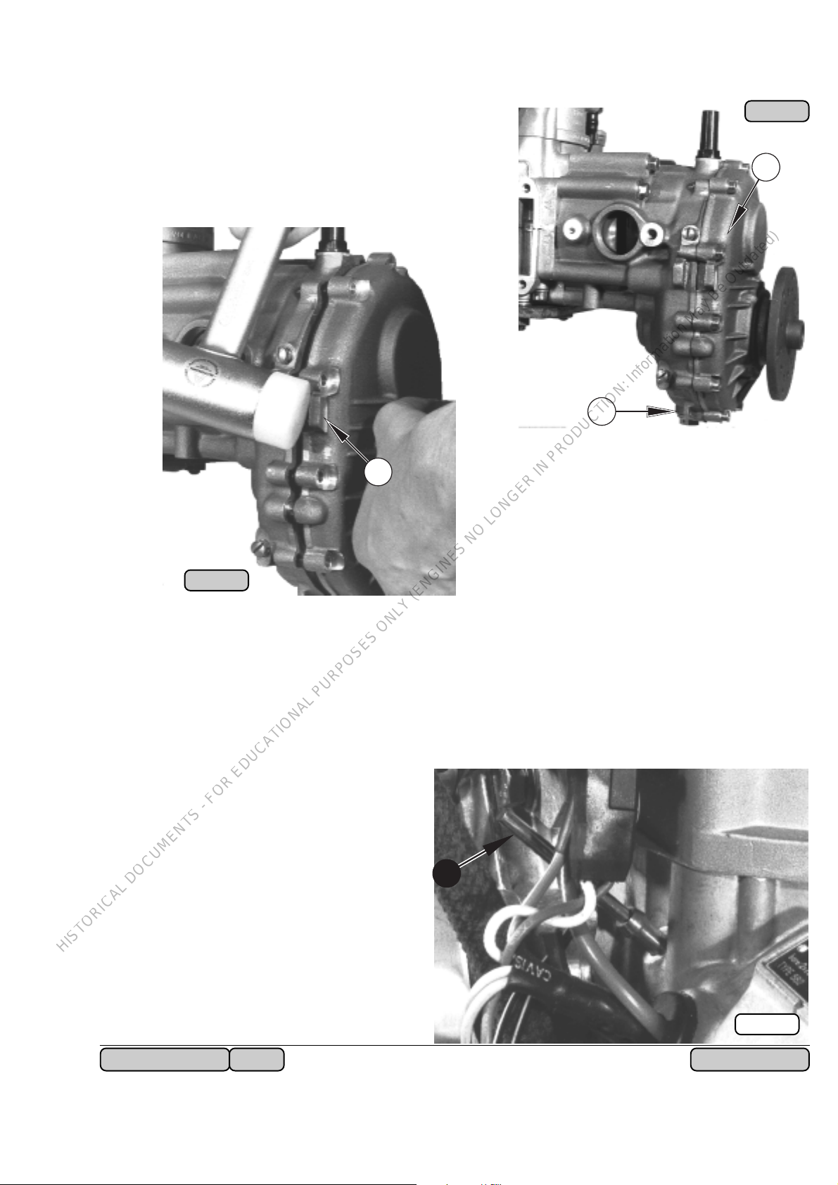
5.3) Disassembly of reduction gearbox „C“:
HISTORICAL DOCUMENTS - FOR EDUCATIONAL PURPOSES ONLY (ENGINES NO LONGER IN PRODUCTION: Information May Be Outdated)
Undo drain plug Q and drain gear oil, c. 0,2
l. Remove 11 Allen screws W M6x30 attach-
ing gear cover to the gear housing.
3
Remove gear cover by tapping cover on the
lugs E, using a mallet. Gear cover is kept in
position by 2 dowel pins.
Ill. 12
2
1
Ill. 13
Lock crankshaft by inserting locking pin 876 640 R into pulse hose nipple and turning
crankshaft until pin engages in crank blade recess. With crankshaft locked in this
manner, all attachment nuts and screws can be slackened or tightened.
■ ATTENTION: Use genuine
locking pin
only, to prevent
any damage to
crankcase.
4
Ill. 14
Rm. 462-532-582 UL 10-1994
- 25 - of 170

Remove Allen screw M8 x 35 and
HISTORICAL DOCUMENTS - FOR EDUCATIONAL PURPOSES ONLY (ENGINES NO LONGER IN PRODUCTION: Information May Be Outdated)
withdraw pinion shaft Q.
◆ NOTE: Placed on the back-
side of the pinion
are the shims for
proper axial distance of pinion
shaft.
Remove the 8 hex. collar screws W,
4 of them inside the gearbox housing,
using socket spanner 11 A/F and pull
off gearbox housing.
1
1
2
Ill. 15
Fit worm-thread hose clamp
3
4
7
6
Remove coupling flange Y together with the rubber coupling U and afterwards hex.
hd. screw 1/2-20 UNF x 30 along with washer. Slightly grease mushroom shaped
protection piece
onto crankshaft and fit fly wheel
puller I
screws M10x45 and pull off flywheel O by turning-in hex. hd.
screw M16.
5
877 415
877 425
using hex.
851 160
Ill. 16
, place it
E tight around rubber coupling and remove 3
Allen screws M10 x 45 R using
Allen key 8.
◆ NOTE: To prevent any damage
to rubber coupling U,
hold washer with flats
T in position, using open
end spanner 17 A/F.
9
8
◆ NOTE: If need be, facili-
tate with a smart
blow of the hammer to screw P.
Put aside flywheel and protection
piece.
- 26 - of 170
Rm. 462-532-582 UL10-1994
10
Ill. 17

5.4) Removal of rewind starter:
HISTORICAL DOCUMENTS - FOR EDUCATIONAL PURPOSES ONLY (ENGINES NO LONGER IN PRODUCTION: Information May Be Outdated)
Note position of rewind starter. Remove 4 hex. hd. screws M6 x 14 along
with lock washer and take off rewind
starter ass’y. Detach the starter pulley Q by removal of the 3 hex. hd.
screws M8x16 together with lock
washer.
◆ NOTE: Crankshaft still locked!
Ill. 18
On engine type 582 UL, starting
2
1
with engine no. 4,015.239 a hydraulic damper W is fitted between
magneto housing and starter pulley Q, to suppress bending- and
torsional vibration of crankshaft.
Remove this damper if fitted.
Ill. 19
5.5) Dismantling of electric starter:
Before removing electric starter, record
its position. Take off starter after removal of 4 hex. hd. screws M6 x 40
along with lock washer.
Ill. 20
Rm. 462-532-582 UL 10-1994
- 27 - of 170

Ill. 21
HISTORICAL DOCUMENTS - FOR EDUCATIONAL PURPOSES ONLY (ENGINES NO LONGER IN PRODUCTION: Information May Be Outdated)
1
Loosen 3 hex. hd. screws M8 x
40 and remove starter gear Q
and starter adaptor placed behind.
On engine type 582 UL, starting
with engine no.
draulic damper is fitted between
magneto housing and starter gear
adapter, to suppress bendingand torsional vibration of crankshaft. Remove this damper if fitted.
4,015.239
a hy-
5.6) Removal of exhaust
manifold:
Note position of exhaust manifold.
Undo Allen screws M8x30 and
remove manifold along with
gaskets. No screw fitted in
position W .
2
Ill. 22
5.7) Removal of ignition coils support plate and disassembly of rotary valve:
5.7.1) Engine type 462 UL:
Undo hex. hd. screw M8 x 25, common for support tie E and rotary valve cover.
Mark wiring from charging coil
Ill. 23
to ignition coils prior to opening
of connection and take off resistor-spark plug connectors, or
shielded spark plug connectors.
Remove the 3 hex. hd. screws
M6 x 22 and take off support
plate ass’y with ignition coils
and ignition damping box.
3
- 28 - of 170
4
◆ NOTE: Take care of the
spacers R behind
the support plate.
Rm. 462-532-582 UL10-1994

Slacken clamp and remove oil supply hose.
HISTORICAL DOCUMENTS - FOR EDUCATIONAL PURPOSES ONLY (ENGINES NO LONGER IN PRODUCTION: Information May Be Outdated)
◆ NOTE: Drain oil of rotary valve drive into suitable container.
Take off water outlet socket or water outlet bend by removing the 2 M6 hex. nuts
along with lock washers and washers.
◆ NOTE: A thermostat might be fitted between water outlet piece and
cylinder head (see Ill. 27).
Remove all 4 hex. hd. screws and washers attaching rotary valve cover on
crankcase.
Remove all spark plugs and crankshaft locking pin Q and turn crankshaft into
T.D.C. position of magneto side piston. Mark position of rotary valve as
depicted and take off rotary valve.
■ ATTENTION:
While removing rotary valve
cover, hold rotary valve with a
pencil for instance, in position
ensuring it will remain on shaft,
thus enabling to check if rotary
valve timing was correct.
◆ NOTE: If locking pin is used on engine type 462 UL, position
magneto side piston on T.D.C. On Engine type 532 UL and
582 UL, set piston to T.D.C on power take off side.
5.7.2) Engine type 532 and 582 UL:
Slacken hose clamp W and remove oil supply line to rotary valve drive.
◆ NOTE: Drain oil of rotary valve drive (c. 0,3 l) into
Ill. 24
1
suitable container.
2
Ill. 25
Rm. 462-532-582 UL 10-1994
- 29 - of 170

Ill. 26
HISTORICAL DOCUMENTS - FOR EDUCATIONAL PURPOSES ONLY (ENGINES NO LONGER IN PRODUCTION: Information May Be Outdated)
4
1
3
2
tors, tilt ignition coils support assembly forward, slacken hose clamps and
remove electronic boxes assembly
together with oil tank and hoses.
Remove water outlet socket or
water outlet bend E along with
gaskets from cylinder head.
It is advisable to detach
supporting plate of ignition coils prior to the removal of oil hoses. For
that undo the 2 nuts Q
M6 and both hex. hd.
screws W M8x25 along
with washers.
Sever all tie straps on oil
lines and cables and
open all wiring connections to electronic boxes
or ignition coils. Take off
all 4 spark plug connec-
Ill. 27
5
◆ NOTE: A thermostat T
might be fitted
between water
outlet piece R
and cylinder.
Remove the last 2 hex. hd. screws U and washers attaching rotary valve cover
on crankcase.
Remove all spark plugs and crankshaft locking pin. Turn crankshaft into T.D.C.
position of magneto side piston, mark position of rotary valve as shown on
illustration 24 and take off rotary valve.
Ill. 28
6
6
■ ATTENTION: At removal of rotary valve cover
hold rotary valve Y in positionwith
a appropriate tool, thus ensuring
that valve will stay on shaft enabling to check if rotary valve timing was correct.
▲ WARNING: "Do not " use finger to apply pres-
sure on rotary valve, as injury
may result.
7
- 30 - of 170
Rm. 462-532-582 UL10-1994
 Loading...