


Series Practix
Practix 285.230 G
Manual/Pulldown
Operating instructions
Before transporting and using the machine,
please read the instructions thoroughly!
Seriové číslo / Serien Nummer / Serial Number ___________________

2
Manual version: 1.03/ Feb. 2010
Manual rev.: 1
Service and information
Your BOMAR dealer
:
Direct BOMAR contact:
BOMAR spol. s r.o.
Těžební 1236/1
62700 Brno
Czech Republic, EU
Phone: +420 – 533 426 100
Fax: +420 – 533 426 109
e-mail: info@bomar.cz
www: http://www.bomar.cz
We are available:
Mondays to Fridays 700 – 1600
Version:
1.03 / Feb. 2010
rev. 1
BOMAR, spol. s r.o. © – Subject to modifications and amendments.

3

4
Manual version: 1.03/ Feb. 2010
Manual rev.: 1

5

6
Manual version: 1.03/ Feb. 2010
Manual rev.: 1

7
Content
1. SAFETY NOTES ........................................................................ 9
1.1. Band saw using ......................................................................................................................................................................... 11
1.2. Protective suit and personal safety .............................................................................................................................. 11
1.3. Safety notes for machine operator .............................................................................................................................. 12
1.4. Safety notes for the servicing and repairs ............................................................................................................... 12
1.5. Safety machine accessories .............................................................................................................................................. 13
1.5.1. TOTAL STOP but ton ........................................................................................................................................... 13
1.5.2. Saw arm cover ....................................................................................................................................................... 13
1.5.3. Saw band cover .................................................................................................................................................... 13
1.5.4. Koncový spínač pohonu pásu u stroje typu manual .................................................................... 13
1.6. Safety notes for cooling system ..................................................................................................................................... 14
1.6.1. Instructions for first help ................................................................................................................................. 14
1.7. Umístění štítku stroje / Maschinenschild position / Position of machine label .............................. 14
1.8. Umístění bezpečnostních značek / Verteilung der Sicherheitszeichen / Position of safety
symbols .......................................................................................................................................................................................... 15
2. MACHINE DOCUMENTATION ................................................17
2.1. Technická data / Technische Daten / Technical data ...................................................................................... 19
2.2. Rozměrové schéma / Aufstellzeichnung / Installation diagram – Practix 285.230 G Manual 20
2.3. Rozměrové schéma / Aufstellzeichnung / Installation diagram – Practix 285.230 G Pulldown21
2.4. Popis / Beschreibung / Description – Practix 285.230 G Manual ............................................................. 22
2.5. Popis / Beschreibung / Description – Practix 285.230 G Pulldown ......................................................... 23
2.6. Transportation and stocking ............................................................................................................................................ 24
2.6.1. Conditions for transportation and stocking ....................................................................................... 24
2.7. Transport and stocking preparations ......................................................................................................................... 24
2.8. Transport and stocking ........................................................................................................................................................ 24
2.9. Kotevní plan / Verankerungsplan / Grounding plan ...................................................................................... 25
2.10. Activation ......................................................................................................................................................................... 26
2.10.1. Machine working conditions ................................................................................................................ 26
2.10.2. Band saw unpacking and assembling ............................................................................................ 26
2.11. Machine installing and levelling ....................................................................................................................... 26
2.12. Machine disposal after lifetime .......................................................................................................................... 26
2.13. Electrical connection ............................................................................................................................................... 26
2.13.1. Check the direction of the saw band .............................................................................................. 27
2.14. Filling of the cooling system ............................................................................................................................... 27
2.15. Check machine function ........................................................................................................................................ 28
2.16. Saw band.......................................................................................................................................................................... 28
2.16.1. Saw band size ................................................................................................................................................. 28
2.16.2. Selection of the saw band tooth system....................................................................................... 28
2.16.3. Saw band running-in ................................................................................................................................. 29
2.16.4. Tables for teeth selection ........................................................................................................................ 30
3. MACHINE CONTROL ..............................................................31
3.1. Control elements for Practix 285.230 G Manual .................................................................................................. 33
3.2. Control elements for Practix 285.230 G Pulldown ............................................................................................. 33
3.3. How to use band saw ........................................................................................................................................................... 34
3.3.1. Cutting ........................................................................................................................................................................ 34
3.3.2. Interruption in cutting with Emergency button TOTAL STOP................................................ 35
3.3.3. Setting of cutting speed ................................................................................................................................. 35
3.3.4. Angular cut setting ............................................................................................................................................. 35
3.3.5. Optimal adjusting of the guide cubes span ....................................................................................... 36
3.4. Material insertion ..................................................................................................................................................................... 36
3.4.1. Handling agent selection ............................................................................................................................... 36
3.4.2. Insertion ..................................................................................................................................................................... 36
3.4.3. Bundle material cutting ................................................................................................................................... 37
4. MACHINE SERVICE ................................................................39
4.1. Saw band dismantling ......................................................................................................................................................... 41
4.2. Saw band installation ............................................................................................................................................................ 41
4.3. Saw band stretching and inspection .......................................................................................................................... 41
4.3.1. Saw band stretching .......................................................................................................................................... 41
4.3.2. Saw band inspection ......................................................................................................................................... 42
4.4. Cooling agents and chips disposal .............................................................................................................................. 42
4.4.1. Coolant device ins pection ............................................................................................................................. 42
4.4.2. Chips disposal ........................................................................................................................................................ 43
4.5. Greases and oils ........................................................................................................................................................................ 43
4.5.1. Gearbox oils ............................................................................................................................................................. 43
4.5.2. Lubricant greases ................................................................................................................................................. 44
4.6. Machine cleaning .................................................................................................................................................................... 44

8
Manual version: 1.03/ Feb. 2010
Manual rev.: 1
5. TROUBLESHOOTING ............................................................. 45
5.1. Mechanical problems ........................................................................................................................................................... 47
5.2. Electrical problems ................................................................................................................................................................. 49
6. SCHÉMATA / SCHEMAS / SCHEMATICS ............................... 51
6.1. Elektrické schema / Elektroschema / Wiring diagrams – Practix 285.230 G Manual .................... 52
6.1.1. Kusovník elektrosoučástí / Stückliste der Elektroteilen / Piece list of elektroparts –
Practix 285.230 G Manual ..................................................................................................................................................... 54
6.2. Elektrické schema / Elektroschema / Wiring diagrams – Practix 285.230 G Pulldown ............ 55
6.2.1. Kusovník elektrosoučástí / Stückliste der Elektroteilen / Piece list of elektroparts –
Practix 285.230 G Pulldown ................................................................................................................................................ 57
7. VÝKRESY SESTAV PRO OBJEDNÁNÍ NÁHRADNÍCH DÍLŮ /
ZEICHNUNGEN FÜR BESTELLUNG DER ERSATZTEILE / DRAWING
ASSEMBLIES FOR SPARE PARTS ORDER ....................................... 59
7.1. Pila / Säge / Saw – Practix 285.230 G Manual ........................................................................................................ 60
7.2. Kusovník / Stückliste / Piece list Pila / Säge / Saw – Practix 285.230 G Manual ............................. 61
7.3. Pila / Säge / Saw – Practix 285.230 G Pulldown ................................................................................................... 62
7.4. Kusovník / Stückliste / Piece list Pila / Säge / Saw – Practix 285.230 G Pulldown ......................... 63
7.5. Rameno / Arm / Arm – Practix 285.230 G Manual ............................................................................................. 64
7.6. Kusovník / Stückliste / Piece list Rameno / Arm / Arm – Practix 285.230 G Manual .................... 65
7.7. Rameno / Arm / Arm – Practix 285.230 G Pulldown ......................................................................................... 66
7.8. Kusovník / Stückliste / Piece list Rameno / Arm / Arm – Practix 285.230 G Pulldown .............. 67
7.9. Podstavec / Untergestell / Piedestal – Practix 285.230 G Manual ............................................................ 68
7.10. Kusovník / Stückliste / Piece list Podstavec / Untergestell / Piedestal – Practix 285.230
G Manual ....................................................................................................................................................................................... 69
7.11. Podstavec / Untergestell / Piedestal – Practix 285.230 G Pulldown .......................................... 70
7.12. Kusovník / Stückliste / Piece list Podstavec / Untergestell / Piedestal – Practix 285.230
G Pulldown .................................................................................................................................................................................. 71
7.13. Svěrák / Schraubstock / Vice ................................................................................................................................ 72
7.14. Kusovník / Stückliste / Piece list Svěrák / Schraubstock / Vice ..................................................... 73
7.15. Napínání pásu / Sägebandspannung / Saw band tensing.............................................................. 74
7.16. Kusovník / Stückliste / Piece list Napínání pásu / Sägebandspannung / Saw band
tensing ........................................................................................................................................................................................... 75
7.17. Vedení pásu / Bandführung / Band guiding ............................................................................................. 76
7.18. Kusovník / Stückliste / Piece list Vedení pásu / Bandführung / Band guiding ................... 77
7.19. Pohon / Antrieb / Drive........................................................................................................................................... 78
7.20. Kusovník / Stückliste / Piece list Pohon / Antrieb / Drive ................................................................ 79
7.21. Konzola / Konsole / Console ................................................................................................................................ 80
7.22. Kusovník / Stückliste / Piece list Konzola / Konsole / Console ..................................................... 81
7.23. Chlazení / Kühlung / Cooling .............................................................................................................................. 82
7.24. Kusovník / Stückliste / Piece list Chlazení / Kühlung / Cooling ................................................... 83

9
Bezpečnostní pokyny
Sicherheitshinweise
Safety notes
1. Safety notes

10
Manual version: 1.03/ Feb. 2010
Manual rev.: 1
Bezpečnostní pokyn
y
Sicherheitshinweise
Safety notes

11
Bezpečnostní pokyny
Sicherheitshinweise
Safety notes
The operating instructions must be read by the person, who keeps in touch with the
machine before transportation, installation, using, servicing, reparation, stocking or
removal!
The operating instructions include relevant information. The operator must familiarise
himself with the install and operation, safety notes and machine servicing, because
reliability and service life must be reached. The operating instructions must avoid risks,
which are linked to work on the machine. Before transporting and using of the
machine, please read the instructions thoroughly!
1.1. Band saw using
The band saw Practix 285.230 G Manual or Practix 285.230 G Pulldown is used for
cutting and shortening of rolled bars and drawn bars and profiles from steels, stainless
steels, non-ferrous metals and plastics with cutting angles from 0° to 60°.
Combustible materials are excepted for cutting! Any other usage and operation
outside this range are unauthorized and the manufacturer/supplier does not accept
any responsibility for any damages resulting from such misuse. The operator has full
responsibility!
The machine is equipped with safety and protective guarding for operator and
machine protection. Nevertheless, this safety and protective guarding cannot prevent
injury. Service personnel must read this chapter and comprehend it, before he starts to
work on the machine. Always keep instructions about work safety! Service personnel
must take into account other aspects of the risk, which refer to the ambient conditions
and the material.
1.2. Protective suit and personal safety
Wear tight fitting overalls! Loose fitting clothes may be caught with machine parts
and cause serious injury.
Wear protective gloves! Material cuts and saw band have sharp edges and may cause
serious injuries.
Wear protective shoes with non-skid soles! The unsuitable shoes may cause balance
loss and following injury. Falling work pieces may cause serious injuries too.
Wear protective goggles! Chips and cooling liquid may damage your eyes.
Always wear ear protections! Most of the machines emit up to 80 dB and may
damage your hearing.
Do not wear jewellery and always tie back long hair! Moving machine parts can
catch jewellery or loose hair and may cause serious injuries.
Operate the machine only when you are fit enough to work. Illnesses or injuries
diminish concentration. Avoid machine work, which may compromise the safety of you
and your colleagues!
Attention!
The operating instructions must be available at the machine!
Keep the operating instructions in good condition!
Attention!
Consider the safety signs on the machine. Do not remove or
damage them!
Attention!
Gloves you can use only at working material replacement (saw
band)! The machine and accessories must be inactive!
If the machine is running, you must not wear gloves! It is
dangerous, because some parts of the machine can catch
gloves!

12
Manual version: 1.03/ Feb. 2010
Manual rev.: 1
Bezpečnostní pokyn
y
Sicherheitshinweise
Safety notes
1.3. Safety notes for machine operator
Machine can be operated only by one person. Machine operator is responsible for
presence of other persons by the machine.
Close covers before the machine starting and check, if the covers are not damaged.
Damaged covers must be repaired or changed. Do not start the machine, if the cover is
removed! Check, if the electric cables are not damaged.
• Do not hold the material for clamping to the vice and for cutting!
• Do not operate with the buttons and the switches on the control panel, if you
have gloves!
• For machine starting take care, that there is nobody in the working area of the
machine (it means in the working area of the vice, the saw band, the saw arm etc.).
• In no circumstances touch the rotating elements.
• Work on the machine only when the machine is in good condition!
• Check at least once in a shift, if the machine is not damaged. If the machine is
damaged, you must bring the machine in order and you must inform your
superior!
• Keep your working area clean!
• Ensure sufficient lighting in the working area.
• Take off the spilt water or the oil from the floor and dry it! Do not touch the
cooling liquid with bare hands!
• Do not set the nozzle of the cooling liquid, when the machine is started on!
• Do not remove the chips from the working area of the machine, when the
machine is started on!
• Do not use the compressed air for the machine cleaning or for the chips
removing! Use the protective instruments for chips removal!
1.4. Safety notes for the servicing and repairs
Switch off the main switch and lock it, before you start service work! When repair
machine remove power cord from the outlet. Otherwise, there is possibility of
hazardous machine starting.
Attention!
Machine can be operated by person older than 18 years!
Machine can be operated only person physically and mentally
fit for this activity.
Keep instructions and orders about work safety!
Read the operating instructions, before you start to work on
the machine! Keep the operating instructions in good
condition!
Do not connect the machine to electricity if the covers are
removed. Do not touch the electrical equipment.
Attention!
Only a qualified professional can carry out the servicing and
repairs of the electric equipment! Take special care during the
work with electrical equipment. High voltage shock can have
fatal consequences! Always keep notes about work safety!
Otherwise, there is possibility of heavy injury.
13
Bezpečnostní pokyny
Sicherheitshinweise
Safety notes
Only qualified person can do the servicing and repairs. For parts changing, use only
parts, which are identical with the originals. Otherwise, there is possibility of health
hazard.
Use only recommended type of the hydraulic oils and oils and lubricants.
Do not remove or do not lock the limit switches or safety equipments! Any use of the
saw, accessories or machine parts other than that intended by the BOMAR, spol. s r.o.
company is not permitted.
The guarantee on this product will be afterward lost and BOMAR, spol. s r.o. takes no
responsibility for caused damages!
1.5. Safety machine accessories
The machine is equipped with safety accessories. It protects the operator from injuries
and the machine before damage. The safety accessories are blocking accessories,
emergency switches and covers. Check once in a week the function of the safety
accessories. If the safety accessories are functionless, you must stop work and repair or
change the safety accessories.
1.5.1. TOTAL STOP button
TOTAL STOP button is used for emergency switching – off the machine in case defect
or health hazard. By pressing TOTAL STOP button is interrupted the supply of the
electrical power.
Release the pressing button is possible by twisting of the upper part of the button.
1.5.2. Saw arm cover
The band saw is stated to the operation, when the cover is closed!
1.5.3. Saw band cover
This protective cover envelops the saw band in the area from guiding cube to the arm.
Never switch the saw band on if this cover is not mounted!
1.5.4. Koncový spínač pohonu pásu u stroje typu manual
Verze stroje typu Manual obsahuje koncový spínač pohonu pásu, který odpojí pohon
pilového pásu po dořezání materiálu a klesnutí ramene do spodní polohy.
Enhanced risk!
Do not come into or intervene in the cutting area.
Otherwise, there is possibility of heavy injury.
If any damages or fault appears, immediately press TOTAL
STOP button!

14
Manual version: 1.03/ Feb. 2010
Manual rev.: 1
Bezpečnostní pokyn
y
Sicherheitshinweise
Safety notes
1.6. Safety notes for cooling system
1.6.1. Instructions for first help
1. Pull off and safely remove polluted, soaked clothing.
2. For breathing, go out in the fresh air or look for first aid treatment.
3. Wash with water or use crèmes for contact with the skin.
4. Flush with water for eyes and look for first aid treatment.
5. For swallowing – drink a lot of water and induce vomiting. Look for medical help.
1.7. Umístění štítku stroje /
Maschinenschild position /
Position of machine label
Štítek stroje umístěn na pilovém rameni, v blízkosti šroubu napínání pásu.
Attention!
Keep notes about work safety for handling cooling liquid!
When handling cooling agents always wear hazardous fluidproof gloves!
Wear protective goggles! Cooling liquid can get in contact
with your eyes and may cause permanent severe injuries.

15
Bezpečnostní pokyny
Sicherheitshinweise
Safety notes
1.8. Umístění bezpečnostních značek /
Verteilung der Sicherheitszeichen /
Position of safety symbols
16
Manual version: 1.03/ Feb. 2010
Manual rev.: 1
Bezpečnostní pokyn
y
Sicherheitshinweise
Safety notes
Poz.
Pos.
Pos.
Obj. číslo
Bestell - Nr.
Reference No.
Název položky
Bezeichnung
Item
ks
Mng.
Pcs.
1 99.900.039
Samolepka /
Aufkleber /
Self-adhesive label
NS – Nebezpečí
stlačení /
Pressunggefahr /
Crushing hazard
1
2 99.900.040
Samolepka /
Aufkleber /
Self-adhesive label
NR – Nebezpečí
říznutí /
Schnittgefahr /
Cutting or severing
hazard
2
3 99.900.045
Samolepka /
Aufkleber /
Self-adhesive label
NE – Nebezpečí
úrazu elektrickým
proudem /
Verletzunggefahr
vom elektrischen
Strom / Electrical
hazard
1
4 99.900.047
Samolepka /
Aufkleber /
Self-adhesive label
OBS – Noste
ochranné brýle a
sluchátka / Tragen
Sie eine Schutzbrille
und Gehörschutz /
Wear protective
googles and
headphones
1
5 99.900.048
Samolepka /
Aufkleber /
Self-adhesive label
PO – Noste pevnou
pracovní obuv /
Tragen Sie
Sicherheitsschuhe /
Wear fixed
protective shoes
1
6 99.900.049
Samolepka /
Aufkleber /
Self-adhesive label
CZ – Přečíst návod
k použití /
Bedienungsanleitun
g lesen / read the
operating
instructions
1
7 99.900.050
Samolepka /
Aufkleber /
Self-adhesive label
SOL – Směr otáčení
doleva /
Drehrichtung nach
links / direction of
rotation left
1
8 99.900.051
Samolepka /
Aufkleber /
Self-adhesive label
SOL – Směr otáčení
doprava /
Drehrichtung nach
rechts / direction of
rotation right
1
99.900.053
Samolepka /
Aufkleber /
Self-adhesive label
Směr pohybu /
Bewegungsrichtung
/
Direction of motion
1

17
Dokumentace stroje
Dokumentation der Maschinen
Machine documentation
2. Machine
documentation

18
Manual version: 1.03/ Feb. 2010
Manual rev.: 1
Dokumentace stroje
Dokumentation der Maschinen
Machine documentation
Sf

19
Dokumentace stroje
Dokumentation der Maschinen
Machine documentation
2.1. Technická data /
Technische Daten /
Technical data
Hmotnost stroje / Maschinengewicht / Machine weight:
• Hmotnost / Gewicht / Weight
Manual 215 kg / Pulldown 225 kg
Rozměry stroje / Maschinengröße / Machine size – Practix 285.230 G Manual:
• Délka / Länge / Lenght
• Šířka / Breite / Width
• Výška / Höhe / Height
1410 mm
915 mm
1270 mm
Rozměry stroje / Maschinengröße / Machine size – Practix 285.230 G Pulldown:
• Délka / Länge / Lenght
• Šířka / Breite / Width
• Výška / Höhe / Height
1410 mm
920 mm
1520 mm
Akustický tlak / Schalldruckpegel / Acoustic pressure:
• Practix 285.230 G Manual
• Practix 285.230 G Pulldown
L
Aeqv
= 62,6/69,4 dB … 35 m.min-1 / 72 m.min-1
L
Aeqv
= 59,5/65,4 dB … 35 m.min-1 / 72 m.min-1
Virbrace / Vibration / Vibration:
• Practix 285.230 G Pulldown
0,08/0,2 m.s
-2
… 35 m.min-1/72 m.min-1
Pohon / Atrieb / Drive:
• Typ / Typ / Type
• Napájení / Versorgungsspannun / Supply voltage
• Výkon / Leistung / Output
• Jmenovité otáčky / Motornenndrehzahl / Nominal speed
MSD90L-8/4
~3×400 V, 50 Hz
0,7/1,1 kW
1400/690 min-1
Chladící zařízení / Kühlmiteleinrichtung / Cooling equipment:
• Typ / Typ / Type
• Napájení / Versorgungsspannun / Supply voltage
• Obsah nádrže / Volumen vom Kühlmittel / Capacity
S1
~ 1×230V, 50Hz
15 l
Rozměr pásu / Sägebanddimension / Band size:
2720×27×0,90 mm
Řezná rychlost / Schnittgeschwindigkeit / Cutting speed:
35/72 m.min-1
Řezné rozsahy / Schnittbereiche / Cutting size:
0° Ø225 mm 280×70 mm 245×225 mm 225×225 mm
R 45° Ø180 mm 180×125 mm 200×170 mm 170×170 mm
R 60° Ø120 mm 115×95 mm 95×95 mm 95×95 mm
Level of acoustic pressure – Practix 280.230 G:
Equivalent level of acoustic pressure A (noise) at operator position are L
Aeqv
=62,6 / 69,4 dB for
35 m.min-1 / 72 m.min-1 for Manual version and L
Aeqv
= 59,5 / 65,4 dB for 35 m.min-1 / 72 m.min-1 for
Pulldown version. Mentioned values are levels of emission which doesn’t have to represent safe
levels. Factors which influence real level of acoustic pressure on machine operator are: working place
characteristics, cut material, saw band. These factors have significantly influence on acoustic pressure.

20
Manual version: 1.03/ Feb. 2010
Manual rev.: 1
Dokumentace stroje
Dokumentation der Maschinen
Machine documentation
Sf
2.2. Rozměrové schéma /
Aufstellzeichnung /
Installation diagram – Practix 285.230 G Manual

21
Dokumentace stroje
Dokumentation der Maschinen
Machine documentation
2.3. Rozměrové schéma /
Aufstellzeichnung /
Installation diagram – Practix 285.230 G Pulldown

22
Manual version: 1.03/ Feb. 2010
Manual rev.: 1
Dokumentace stroje
Dokumentation der Maschinen
Machine documentation
Sf
2.4. Popis /
Beschreibung /
Description – Practix 285.230 G Manual

23
Dokumentace stroje
Dokumentation der Maschinen
Machine documentation
2.5. Popis /
Beschreibung /
Description – Practix 285.230 G Pulldown

24
Manual version: 1.03/ Feb. 2010
Manual rev.: 1
Dokumentace stroje
Dokumentation der Maschinen
Machine documentation
Sf
2.6. Transportation and stocking
2.6.1. Conditions for transportation and stocking
Keep recommendations for the manufacturers for transportation and stocking! If the
recommendations are not kept, damage can occur to the machine.
• Do not use a forklift truck for handling the machine, if you do not have license for
it!
• Do not move under suspended loads! Fault in lifting device may cause serious
injury.
• Keep a safe distance from the machine during the transport.
Conditions for transportation and stocking:
• Temperature of the air from -25°C to 55°C, for a short term
• (max. 24 hours) temperature of the air until 70°C.
• Do not expose the machine to radiation (for example microwave radiation, ultra-
violet radiation, laser radiation, x-ray radiation). Radiation can cause problems with
the machine function and deteriorating condition of the isolation.
• Take measures, to prevent damage by dampness, by vibrations and by shakes.
2.7. Transport and stocking preparations
• Close the vice and thoroughly oil all blank surfaces.
• Lower the saw frame to the lowest position.
• Make sure to empty the machine of all traces of the cooling agent.
• Fasten all loose parts securely to the machine.
• Pack and wrap the control desk securely to avoid damage during transport.
• Fix the stickers stating the minimum approximate machine weight to at least five
well visible places.
• The machine has to be screwed to a pallet for the transport!
2.8. Transport and stocking
Handle the machine only with the hand pallet truck or the forklift truck! If the machine
is equipped with the shackles in the pedestal, you can use the suspension cable and
the crane.
Make sure that the hand pallet truck; the forklift truck or the crane had sufficient
capacity.
Make sure that the van or the trailer had sufficient capacity.
The machine must be secured during transportation. Screw on the palette to the floor
of the van or the trailer. Be careful that the machine is not damaged during
transportation.
Store the machine only under conditions mentioned in the manual, to avoid damage of
the machine.
It is forbidden to handle the machine any other way (for example by, lifting by the saw
frame of the band saw), than it is written in this operating instructions, the machine can
be damaged!

25
Dokumentace stroje
Dokumentation der Maschinen
Machine documentation
2.9. Kotevní plan /
Verankerungsplan /
Grounding plan

26
Manual version: 1.03/ Feb. 2010
Manual rev.: 1
Dokumentace stroje
Dokumentation der Maschinen
Machine documentation
Sf
2.10. Activation
2.10.1. Machine working conditions
Keep the conditions of the manufacturer for machine operating! If recommendations
are not kept, damage can occur to the machine.
The manufacturer warrants the correct function of the machine for these
conditions:
• At temperature air from 5°C to 40°C, the temperature average during 24 hours
must not exceed over 35°C.
• At relative dampness of the air in the extend from 30% to 95% (not concentrate).
• Altitude lower than 1000 metres.
• Do not expose the machine to the radiation (for example microwave radiation,
ultra-violet radiation, laser radiation, x-ray radiation). Radiation can cause problems
with the machine function and deteriorating condition of the isolation.
2.10.2. Band saw unpacking and assembling
Remove the packing from the machine and unpack all parts.
2.11. Machine installing and levelling
Check the floor supporting capacity before machine installing. If the floor capacity does
not agree with requirements, you must prepare the necessary base for the machine.
Minimal requirement:
Machine weight – Practix 285.230 G
Manual 215 kg / Pulldown 225 kg
+ Weight of accessories
+ Maximum weight of material
• The machine must be levelled at the horizontal position. All feet of the machine
must touch with the floor after levelling.
• The machine must be levelled by means of the calibrated spirit level. Spirit level is
put on the vice area. Set the roller conveyors according to the spirit level.
• For machine levelling, take care that there is sufficient available space for
operation, repair work, servicing of the machine and handling the material.
• The machine including appended parts and accessories must be visible from the
place of operation.
2.12. Machine disposal after lifetime
Blown out all service fluids (cooling liquid, hydraulic oil) into designated reservoir.
Dismantle machine into separate parts and dispose them in accordance with valid
directives.
2.13. Electrical connection
Only a qualified professional must carry out the servicing
and repairs of the electric equipment! Take special care
during work with electrical equipment. High voltage shock can
have fatal consequences! Always keep notes about work safety!
Attention!
Switch off the main switch and lock it, before you start
assembly! Otherwise, there is possibility of hazardous machine
starting.

27
Dokumentace stroje
Dokumentation der Maschinen
Machine documentation
Electrical parameters of the machine:
• Service voltage: ~ 3×400 V, 50 Hz, TN-C-S
• Total input / Max. fuse: 1,1 kW / 16 A
Before connecting switch off the main switch of the power supply circuit for the
machine and ensure dry place when doing connecting works!
Service voltage must agree with the line voltage!
Crosscut of the supply line must respond with rated current for max. machine load.
Connect the service cable of the machine on the clamps of the electric distribution.
In case the machine is connected with a direct connection, an extra main switch must
be added which can be locked in zero position.
2.13.1. Check the direction of the saw band
After the machine has been successfully connected, briefly switch on the machine and
put the driving engine of the band in the running position. The direction must be in
accordance with the arrow direction on the saw band cover. In case the direction of the
saw band does not match, two phases at the terminal strip must be switched.
2.14. Filling of the cooling system
Prepare the mixture of the water and the cooling liquid. Keep the concentration
specified by manufacturer.
Fill the mixture of the water and the cooling liquid to the tank of the cooling system.
Area of the tank for the cooling liquid is discovered from the chapter „Technical data“.
Filling the tank with the cooling liquid, take care that the liquid does not drip out of the
tank and the tank does not overflowed.
Note:
The values of the crosscut of the conductor and the rated
current are in the norms.
Note:
The socket with the fork can be used only at the machines with
the rated current less than 16 A and total input less than 3 kW
Attention! In this case the extra main switch becomes primary
and the main switch on the machine has only secondary
function.

28
Manual version: 1.03/ Feb. 2010
Manual rev.: 1
Dokumentace stroje
Dokumentation der Maschinen
Machine documentation
Sf
Keep by manufacturer specified recommendation for adding the anticorrosive agents,
the antifreezes or other agents! For mixture of two different mixes can produce toxic
and aggressive mixes, which can threaten your health or damage cooling system of the
machine
2.15. Check machine function
Check, if the machine or some parts of the machine were not damaged during
transport.
Check, if covers are installed and functional. Check by means of the Tenzomat if the saw
band is correctly stretched. If it is necessary, you can stretch the saw band according to
chapter Selection and replacement of the saw band. Values of the saw band stretching are
on the Tenzomat. Switch on the main switch and check the motors and systems (saw
band drive, hydraulic pump, cooling pump, chips conveyor).
Open and close the main vice. Turn the saw frame of the band saw from one outer
position to other outer position. Raise the saw frame to the top position and drop the
saw frame to the lowest position.
Start the machine with the cooling pump and let it run without load until the cooling
system will be filled with cooling liquid. As soon as the cooling liquid starts to escape
from the nozzles of the cooling system, the cooling system is ready for the operation.
Carry one cycle of cutting without material. Check, if the machine runs with no
irregularities. If all machine functions are right, the machine is ready for operation..
2.16. Saw band
Refit the saw band cover only after you have installed and tightened the saw band.
2.16.1. Saw band size
2720×27×0,90 mm
2.16.2. Selection of the saw band tooth system
The manufacturers provide the saw bands with constant and variable tooth system. The
important factor for selection of the tooth system is length of the cutting canal with
respect to the size of the product.
1. Constant tooth system – the saw band has parallel tooth pitch all over length. This
way is suitable for cutting of solid material.
2. Variable tooth system – tooth pitch is variable. Variable tooth system is used for
profiled materials and bundle cutting. Variable tooth pitch lowers vibration of the
saw band, increases service life of the saw band and quality of the cutting area.
In tables, there are advised type of the tooth system depending on sizes and form of
the cutting material.
Footnotes:
Z
p
Z – teeth number on one inch
S – tooth with zero angle of the teeth
K – tooth with positive angle of the teeth
Examples of the tooth system marking:
32 S – number „32“ means 32 teeth on one inch (that means constant tooth system),
letter „S“ marks teeth with zero angle of the tooth.
4–6 K – number „4–6“ means 4 till 6 teeth on one inch
(that means variable tooth system); letter „K“ marks teeth with positive angle of the
teeth
BOMAR recommends use variable tooth systém.

29
Dokumentace stroje
Dokumentation der Maschinen
Machine documentation
2.16.3. Saw band running-in
To ensure a full service life of the saw bands, we strongly recommend that you carry out
the „RUN-IN“ process.
Running in: Cut the material with the frame lowering reduced to 50% only. When
vibrations occur increase or decrease the band speed.
When cutting small pieces run the band until approximately 300 cm2 of material has
been cut. When cutting large pieces run the band for 15 minutes approximately.
When the band has been run, increase the lowering-speed to normal speed. The
running in of the saw band avoids micro-breaks on the cutting edges of new saw band
ensuing from first excessive stress. This would decrease service life substantially. The
optimal running in of the saw band produces ideal rounded cutting edges and
therefore the conditions for an optimal service life.
Note:
Run regrinding bands too!

30
Manual version: 1.03/ Feb. 2010
Manual rev.: 1
Dokumentace stroje
Dokumentation der Maschinen
Machine documentation
Sf
2.16.4. Tables for teeth selection
SHAPED MATERIAL (Dp, S = mm)
Dp
S
D
p
S
S
Dp
D
p
S
D
p
S
Note: Table shows tooth system selection for cutting one piece of the profile. For cutting of more pieces of the profiles (bundle), you must think of the size of
the wall as double size of the wall of one profile (that means, size „S“ equates to 2×S). In table , there are tooth systems constant and variable.
Size of the
wall
S [mm]
Tooth system (Z
p
Z)
Outer diameter of the profile D
p
[mm]
20 40 60 80 100 120
2 32 S 24 S 18 S 18 S 14 S 14 S
3 24 S 18 S 14 S 14 S 10–14 S 10–14 S
4 24 S 14 S 10–14 S 10–14 S 8–12 S 8–12 S
5 18 S 10–14 S 10–14 S 8–12 S 6–10 S 6–10 S
6 18 S 10–14 S 8–12 S 8–12 S 6–10 S 6–10 S
8 14 S 8–12 S 6–10 S 6–10 S 5–8 S 5–8 S
10 - 6–10 S 6–10 S 5–8 S 5–8 S 5–8 S
12 - 6–10 S 5–8 S 5–8 S 4–6 K 4–6 K
15 - 5–8 S 5–8 S 4–6 K 4–6 K 4–6 K
20 - - 4–6 K 4–6 K 4–6 K 3–4 K
30 - - - 3–4 K 3–4 K 3–4 K
50 - - - - - 3–4 K
Size of the
wall
S [mm]
Tooth system (Z
p
Z)
Outer diameter of the profile D
p
[mm]
150 200 300 500 750 1000
2 10–14 S 10–14 S 8–12 S 6–10 S 5–8 S 5–8 S
3 8–12 S 8–12 S 6–10 S 5–8 S 4–6 K 4–6 K
4 6–10 S 6–10 S 5–8 S 4–6 K 4–6 K 4–6 K
5 6–10 S 5–8 S 4–6 K 4–6 K 4–6 K 3–4 K
6 5–8 S 5–8 S 4–6 K 4–6 K 3–4 K 3–4 K
8 5–8 S 4–6 K 4–6 K 3–4 K 3–4 K 3–4 K
10 4–6 K 4–6 K 4–6 K 3–4 K 3–4 K 2–3 K
12 4–6 K 4–6 K 3–4 K 3–4 K 2–3 K 2–3 K
15 4–6 K 3–4 K 3–4 K 2–3 K 2–3 K 2–3 K
20 3–4 K 3–4 K 2–3 K 2–3 K 2–3 K 2–3 K
30 3–4 K 2–3 K 2–3 K 2–3 K 1,4–2 K 1,4–2 K
50 2–3 K 2–3 K 2–3 K 1,4–2 K 1,4–2 K 1,4–2 K
75 - 2–3 K 1,4–2 K 1,4–2 K 1,4–2 K 0,75–1,25 K
100 - - 1,4–2 K 0,75–1,25 K 0,75–1,25 K 0,75–1,25 K
150 - - - 0,75–1,25 K 0,75–1,25 K 0,75–1,25 K
200 - - - 0,75–1,25 K 0,75–1,25 K 0,75–1,25 K
SOLID MATERIAL (D = mm)
D
D
D
D
D
Constant tooth system Variable tooth system
length of the cut D tooth system (ZpZ) length of the cut D tooth system (ZpZ)
to 3 mm 32
to 30 mm 10 –14
to 6 mm 24
20–50 mm 8–12
to 10 mm 18
25–60 mm 6–10
to 15 mm 14
35–80 mm 5–8
15–30 mm 10
50–100 mm 4–6
30–50 mm 8
70–120 mm 4–5
50–80 mm 6
80–150 mm 3–4
80–120 mm 4
120–350 mm 2–3
120–200 mm 3
250–600 mm 1,4–2
200–400 mm 2
500–3000 mm 0,75–1,25
300–800 mm 1,25
700–3000 mm 0,75
Despite the above recommendations, please follow your supplier’s advice!

31
Ovládání stroje
Bedienung der Maschine
Machine control
3. Machine control

32
Manual version: 1.03/ Feb. 2010
Manual rev.: 1
Ovládání stroje
Bedienung der Maschine
Machine control

33
Ovládání stroje
Bedienung der Maschine
Machine control
3.1. Control elements for Practix 285.230 G Manual
Control elements Description
1. TOTAL STOP button
In emergency causes the machine must
be immediately switched off.
Attention! By pressing Total Stop button
does not stop sinking of the saw arm!
2. Switch of the cutting speed
Choice of the cutting speed during
cutting (35 or 72 m. min-1).
3. Adjustment of saw arm falling
Adjust speed of saw arm sinking during
cutting. Turning the wheel switch on
the cylinder smoothly changes saw arm
sinking speed. Position 0 stops saw arm
sinking. Position 1 is for lowest sinking
speed and position 4 is for highest
sinking speed.
3.2. Control elements for Practix 285.230 G Pulldown
Control elements Description
1. Off saw band drive
Position 0 off saw band drive.
Attention! Position 0 does not
disconnect saw from electrical network
2. Switch of the cutting speed
Choice of the cutting speed during
cutting (35 or 72 m. min-1).
4 Security circuit
Button on top of switch box turn on
security circuit. Security circuit must be
switched on before cutting begins after
saw was disconnected form electrical
network.
3. START AND STOP
Button starts and stops saw band drive.

34
Manual version: 1.03/ Feb. 2010
Manual rev.: 1
Ovládání stroje
Bedienung der Maschine
Machine control
3.3. How to use band saw
3.3.1. Cutting
Picture What to do
1. Insert the material to the vice.
2. Shift the material in claimed length of
cutting.
3. Fix the material by means of clamping
wheel. Come with vice approximately 3
mm to material.
Note: Turning the wheel in clockwise
direction the vice is tightened. Turning the
wheel in counter clockwise direction the vice
is loosened.
4. Vice and clamp the material by means of
detent lever
5. Choose desired cutting speed by
turning the switch on the motor.
6. Check the right and tight fixation of
material once again.
7. For Practix 285.230 G manual 7. For Practix 285.230 G pulldown
• Turn switch no. 3 to adjust speed of saw arm
falling.
• Security circuit must be turn ON by button on pos.
4 before cutting begin.
• Security circuit must be switched ON after every
disconnection from electrical network
• When material is cut, limit switch stops drive of
saw band.
• Start the band saw by pressing button no. „3“
(START) positioned on operating lever. If button
no. „3“ is loosen, driving stops.
• To continue in cutting please repeat points
1–7.
• Is necessary to lead the arm to cut manually.
• To continue in cutting, repeat p. 1–7.

35
Ovládání stroje
Bedienung der Maschine
Machine control
3.3.2. Interruption in cutting with Emergency button TOTAL STOP
Picture What to do
• In emergency causes press button Total Stop
• After pressing Total Stop button the band saw stops
immediately.
3.3.3. Setting of cutting speed
Saw band speed is changeable between 35 and 70 m.min-1.
Picture What to do
• speed 35 m.min
-1
– turn the speed switch to the
position 1
• speed 72 m.min
-1
– turn the speed switch to the
position 2
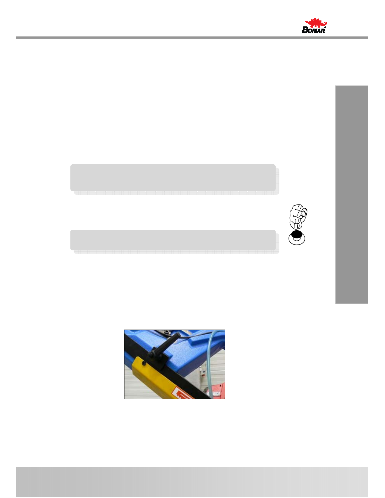
3.3.4. Angular cut setting
The machine enables angular cuts under 60°. The cut angle can be set fluently
from 0° to 60°.
Picture What to do
1. Release securing lever of the console.
2. Swivel the frame to the desired angle by pulling the
stretching star. There is a scale on the console.
Note: When adjusting the angle of the cutting, follow the
marking on the console that indicates the current angle on
the scale.
3. Check the setting according to the scale and tighten
the securing lever of the console
Attention!
Turn carefully with saw arm. Do not hit hard on the saw
arm stops for setting 0 ˚ and 60 ˚.
Note:
When band drive starts, the coolant pump starts automatically
as well. After switching off the band drive, the coolant pump
stops as well.
36
Manual version: 1.03/ Feb. 2010
Manual rev.: 1
Ovládání stroje
Bedienung der Maschine
Machine control
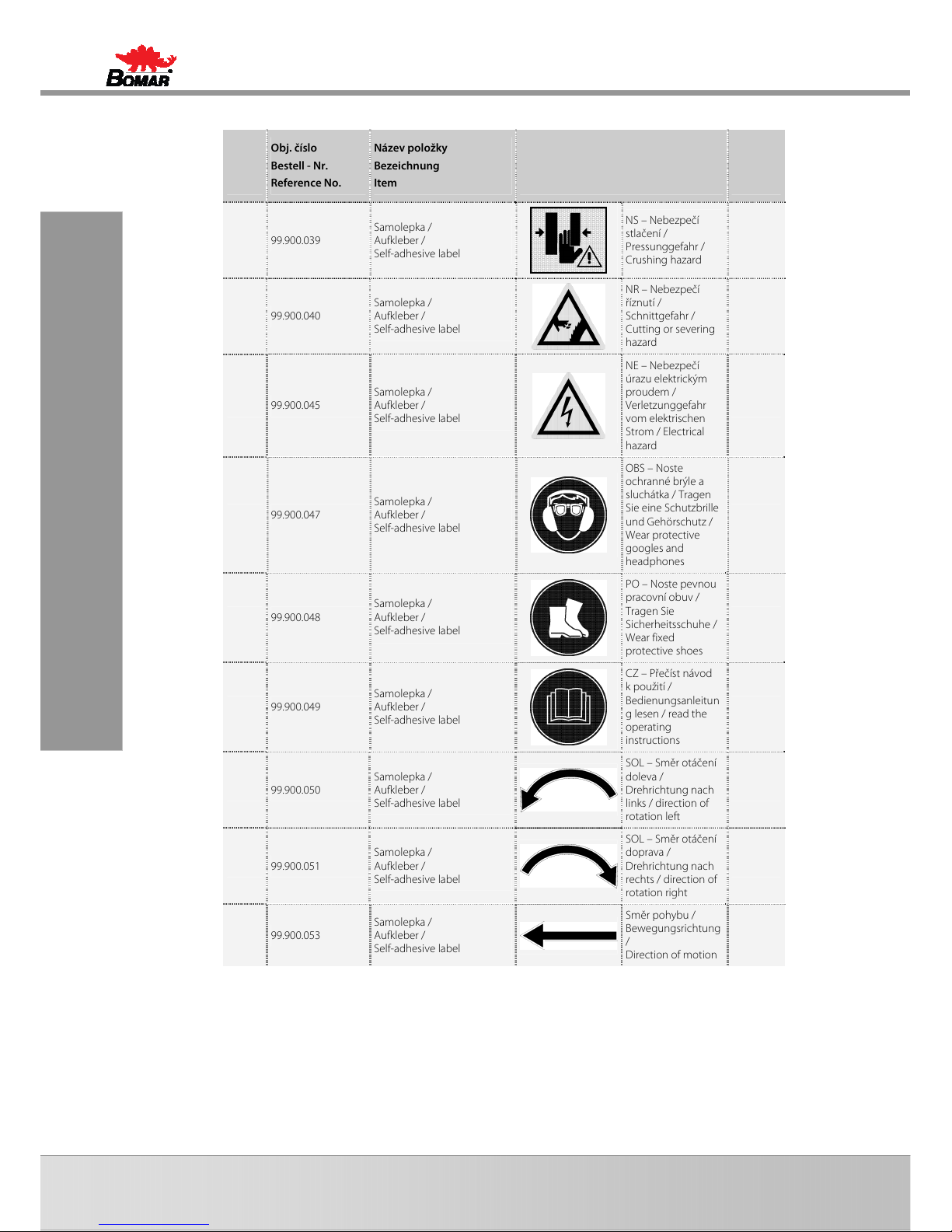
If you can not properly set up mark on console with 0˚ and 60˚ on the scale is
necessary to adjust the screws. By screws adjust properly stops at 0˚ and 60˚.
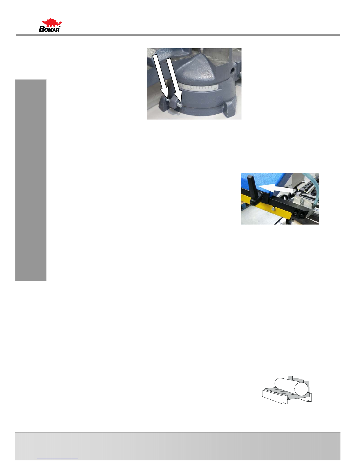
3.3.5. Optimal adjusting of the guide cubes span
If you want to achieve a smooth and precise cut, it is helpful to position the guide cube
as close as possible to the material.
1. Release the lever of the left listel and move left part of the
guide apparatus so that the left guide cube edge is as close
to the cut material as possible.
2. Lower the frame to the lower position and check the
position of the guide cube towards vice loading area. The
guide cube must be a distance of at least 10 mm from the
vice loading area.
3. Tighten the lever of the gib and check the guide cube setting once more for
possible collision with binding table or vice jaw.
3.4. Material insertion
• Never walk under a suspended load!
• Never climb onto the gravity-roller conveyor!
• Do not hold the material for clamping material to the vice! The vice can cause
injury!
3.4.1. Handling agent selection
• Use the strong handling agents to lift and transfer the material!
• Handle with the material only with the lift truck or use the suspension strands and
the crane!
• Do not use the lift truck or crane in case that you do not have the license to handle
with it!
3.4.2. Insertion
Insert material to the vice and ensure that the material cannot move in the vice or fall
from the vice after the clamping. If you cut long pieces of the material (for example rod,
tube), you must use the roller conveyors for material shifting to the band saw. Contact
Bomar for more information about roller conveyors
Make sure the conveyor is long enough and the material cannot tip off the
conveyor.
Be especially careful with round materials that it always stays on two vertical
rollers and that it cannot fall off the conveyor!

37
Ovládání stroje
Bedienung der Maschine
Machine control
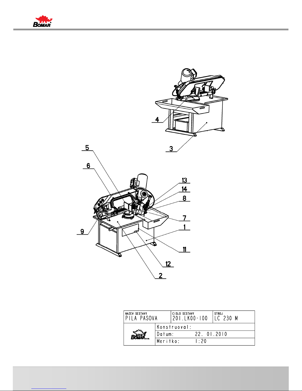
3.4.3. Bundle material cutting
If you want to cut the material in the bundle, there are suggestions for the positioning
of bundles
Round material bundle:. Take care especially with round material that the bars are put
according to the picture. If the bars are put differently, you may have problems with
movement.
Always weld the material at the rear end of the bundle to secure it from moving.
Before welding always, switch the machine off at the main switch! The magnetic fields,
which often occur during welding, may damage the controls!
Square material bundle:
Attention!
Not all shapes of material are suitable for cutting in the
bundle. Follow recommendations of your saw band supplier for
placing material into bundle.

38
Manual version: 1.03/ Feb. 2010
Manual rev.: 1
Údržba stroje
Wartung /
Machine service

39
Údržba stroje
Wartung
Machine service
4. Machine service

40
Manual version: 1.03/ Feb. 2010
Manual rev.: 1
Údržba stroje
Wartung /
Machine service

41
Údržba stroje
Wartung
Machine service
4.1. Saw band dismantling
1. Unplug the machine from the power supply. It guarantees that the machine does
not accidentally start running.
2. Open the protective cover on the rear side of the saw frame. Release the saw band
tension using the handle so that the saw band can be taken out easily.
3. Remove the saw band from rotation wheels.
4. Slide out the saw band from the guides.
4.2. Saw band installation
1. Prior to installation, clean all track wheels, guide cubes and inner side of the arm
thoroughly of all traces of chips and dirt. Keep in mind the teeth direction when
installing the saw band.
2. Insert new saw band in the guide cubes. Make sure the saw band runs between
both guide rollers and it is pushed all the way to the top.
3. Put the saw band on both guide wheels. Make sure that the saw band ridge fit
tightly to the wheel rim. Then push the saw band as far back as possible.
4. By turning the stretching star to the right, you will stretch the saw band slightly.
Now remove the plastic cover of the saw band teeth.
5. Close the rear protective cover.
6. Install the yellow protective cover of the band. The arrow on the cover must match
the direction of the arrow on the band. If it does not, turn the band round.
4.3. Saw band stretching and inspection
Right saw band stretching is one of the most important criteria’s, which influents
accuracy and saw band service life. Stretch the saw bands according to the selected
saw band and the band saw. Keep the recommendation of your manufacturer.
4.3.1. Saw band stretching
1. The saw band must not fall from the wheels after setting.

42
Manual version: 1.03/ Feb. 2010
Manual rev.: 1
Údržba stroje
Wartung /
Machine service
2. Install the Tenzomat on the saw band and secure it with screws.
3. Stretch the saw band until it is stretched to the recommended value.
4.3.2. Saw band inspection
Check the saw band in the guiding cubes and on the wheels
4. Check, if the saw band is right in the guiding cubes..
5. Switch on the saw band drive and then after 10 seconds switch off saw band drive.
If the saw band drive is not possible to switch on, set the limit switch of the saw
band stretching.
6. Switch off the main switch.
7. Open cover(s) of the wheels and check position of the saw band on the both
wheels..
• If the distance between backside of the saw band and the offset wheel is 1 mm,
setting is right..
• If the distance is bigger than 1 mm, or the saw band is on the offset of the wheel,
set the saw band.
8. Close cover of the saw band.
4.4. Cooling agents and chips disposal
The quality of the cooling agent
will deteriorate due to:
If the solution is too weak: If the solution is too strong:
• use of contaminated water
• impurity
• outside oil contamination
(hydraulics, gears)
• high operating temperatures
• lack of air circulation
• wrong concentration
• corrosion protection is
diminished
• lubrication decreases
• microbial attack is more likely
• the cooling ability is decreased
• foam behaviour increases
• emulsions stability deteriorates
• sticky residue develops
4.4.1. Coolant device inspection
The state of the cooling agent has significant influence on the cutting quality and on
the operational life of the machine. Lifetime of the cooling liquid is 1 year, after this time
we recommend change the cooling liquid. This time is dependent on the degree of
pollution cooling liquid (especially with oils) and on the other factors.
Check level of the cooling liquid and function of the pump periodically!
Note:
If the state of the cooling liquid is not satisfactory, the cooling
liquid must be changed.

43
Údržba stroje
Wartung
Machine service
Check the state of the cooling agent according to the following table:
Testing Interval Method Condition Precaution
Liquid level daily visually too low
after concentration check, refill
with water or emulsion
Concentration daily
refractometer
densimeter
too high
too low
refill water
refill base emulsion
Smell daily by sense of smell unpleasant smell
good ventilation, add biocides
or renew coolant
Contamination
daily by sense of smell
visible oil leaks,
sludge fungi
surface cleaning, fix leaks, add
biocides or fungicides, or
coolant renewal after added
system cleanser*
Corrosionprotection
when
necessary
visually
chip test
Herbert-test
insufficient corrosion
protection
test stability, if necessary –
increase concentration or pH
value
Stability
when
necessary
refractometer oiling
add concentrate, enquiries to
supplier
Foam reaction
when
necessary
shaking test
too much foam, foam
disperses too slowly
avoid aeration, increase water
hardness, ix with defoamer
* according to manufacturers’ instructions
4.4.2. Chips disposal
Chips resulting from cutting operations must be disposed of in accordance with the
relevant regulations.
• Let the chips drip excess fluid!
• Fill a watertight container with the chips! Be careful that the container does not
leak, because even after a long dripping time, they still contain coolant residue.
• Place the container into the care of a disposal company equipped for the disposal of
chips contaminated with cooling liquid. In case the machine is equipped with micro-
spray installation, the chips must also be handed over to a disposal company.
4.5. Greases and oils
4.5.1. Gearbox oils
In gearboxes, oil is used for the whole lifetime of the gearbox. We recommend
replacing of the filling oil in case of repair.
Use oils with specification DIN 51517 in the gearboxes. Select the viscosity grade ISO
VG according to the original oil fill.
Comparative table of the gearbox oils:
Manufacturer
Viscosity grade
ISO VG 100 ISO VG 220 ISO VG 320
BP Energol GR-XP 100 Energol GR-XP 220 Energol GR-XP 320
Castrol
Alpha SP 100
Alpha MW 100
Alpha SP 220
Alpha MW 220
Elf Reductelf SP 100
Reductelf SP 220
Reductelf Synthese 220
Reductelf SP 320
Attention:
When replacing, use oils recommended by BOMAR or oils,
which has comparable parameters from the other
manufacturers.
Do not forget, that mineral and synthetic oils must not be
mixed!

44
Manual version: 1.03/ Feb. 2010
Manual rev.: 1
Údržba stroje
Wartung /
Machine service
Manufacturer
Viscosity grade
ISO VG 100 ISO VG 220 ISO VG 320
Esso Spartan EP 100 Spartan EP 220 Spartan EP 320
Mobil Mobilgear 627
Mobilgear SHC 220
Mobilgear 630
Mobilgear 632
ÖMV PG 220
Paramo PP 7 Paramo CLP 220 Paramo CLP 320
Shell Shell Omala 100
Shell Omala 220
Shell Tivela S 220
Shell Omala 320
Shell Tivela S 320
Total Carter EP 100 Carter EP 220 Carter EP 320
4.5.2. Lubricant greases
We recommend using lithium based saponified grease, class NGLI-2 for lubrication.
Different greases are mixable, if their oil bases and consistence type are identical.
Comparative table of the lubricant greases:
Manufacturer Type of the lubricant grease
BP Energrease LS - EP
DEA Paragon EP1
Esso FETT EGL 3144
Beacon EP 1
Beacon EP 2
FINA FINA LICAL M12
Klüber Microlube GB0
Staburags NBU8EP
Isoflex Spezial
Optimol Optimol Longtime PD 0, PD1, PD2
Shell Aseol AG ASEOL Litea EP 806-077
Texaco Multifak EP1
4.6. Machine cleaning
Clean the machine from the cooling liquid and impurities after every shift stopping.
Conserve the guiding surfaces, mainly:
• Vice jaws
• Vices guiding
• Feeder
• Stand area

45
Závady
Troubleshooting
5. Troubleshooting

46
Manual version: 1.03/ Feb. 2010
Manual rev.: 1
Závad
y
Troubleshooting

47
Závady
Troubleshooting
5.1. Mechanical problems
Problem Possible causes Repair
1. Slanting cut
- Wrongly adjusted hard metal guides. Set according to the chapter „Machine service“
- Worn hard metal guides. Replace to the chapter „Worn pieces
replacement“
- Wrongly adjusted cubes of the saw
band guiding.
Set according to the chapter „Machine service“
- Worn bearings of the saw band
guiding.
Replace according to the chapter „Worn pieces
replacement“
- Wrongly adjusted swarf brush. Set according to the chapter „Machine service“
- Worn swarf brush. Replace according to the chapter „Worn pieces
replacement“
- Insufficient saw band stretching. Rise the saw band stretching and set the limit
switch.
- Wrongly chosen tooth system of the
saw band.
Replace the saw band and keep the instructions
of manufacturer on new saw band choice.
- Worn saw band. Replace the saw band.
- Wrongly balanced roller conveyor. Set the roller conveyor.
- Dirty feeding board. Cleanse the feeding board from debris, chip and
residue material.
- Guiding arm and guiding cube are
loosened.
Clamp the guiding arm.
- Guiding arm and cube are too far from
the material.
Set the guiding cube to the material.
- Too fast cutting rate. Lower the material feeding speed.
- Unexpected oscillation in material
quality.
Set the cut and feeding speed to the relevant
material.
2. The cut is not cut
upon desired angle
- Securing lever is loosened. Check the securing lever efficiency and carry out
its adjustment according to chapter „Machine
service“.
- Set angle does not match the cut
angle.
Check the angle adjustment with a protractor
and possibly set it according to chapter
„Machine service“.
- Insufficient saw band stretching. Stretch the saw band and set the limit switch
according to chapter „Machine service“.
- Guiding arm and guiding cube are
loosened.
Fasten the guiding arm and the cube.
- Dirt between material and clamping
jaw.
Cleanse the material and mating jaw.
3. Short lifetime of the
saw band
- Insufficient saw band stretching. Raise the tightening of the saw band set the
scanner of saw band tightening according to
chapter „Machine service“.
- Worn swarf brush. Check the swarf brush condition and replace it in
case of excessive use as described in chapter
„Worn pieces replacement“
- Wrongly adjusted swarf brush. Check swarf brush adjustment, set it according
to chapter „Machine service“
- Over stretched saw band Lower stretching of the saw band and set the
limit switch of the saw band stretching
according to chapter „Machine service“
- Wrongly adjusted hard metal guides. Check the adjustment of the hard metal guides
and carry out adjustment as described in chapter
„Machine service“
- Worn hard metal guides of the saw
band.
Check the condition of the hard metal guide and
if it is too worn, replace hard metal guides
according to chapter „Worn pieces replacement“

48
Manual version: 1.03/ Feb. 2010
Manual rev.: 1
Závad
y
Troubleshooting
Problem Possible causes Repair
- Worn saw band guide bearings. Check guiding bearings and if you notice some
sort of excessive damage, replace them
according to chapter„Worn pieces replacement“
- Wrongly adjusted guiding cubes of the
saw band.
Set guiding cube according to chapter „Machine
service“
- Wrongly adjusted down feed and saw
band speed.
Adjust the feeding and speed of a saw band
according to values published by saw band
manufacturer.
- Different material quality. Adjust feeding and speed of a saw band
according to desired material (try cut-test).
- Low-class saw band Replace the saw band (contact your local
accessory supplier for more information)
- Wrongly chosen saw band tooth
system.
Replace the saw band and keep instructions of
the manufacturer on the choice.
- Wrongly adjusted tracking. Check the space between top of a saw band and
driving wheel. Perhaps adjust the tracking as
described in chapter „Machine service“
4. Insufficient cut
output.
- Worn saw band. Replace the saw band and keep instructions of
the manufacturer on the choice.
- Wrong saw band tooth system. Replace the saw band and keep instructions of
the manufacturer on the choice.
- Wrongly set down feed and speed of a
saw band.
Set feed and speed of a saw band according to
values published by saw band manufacturer.
5. The cut is not
finished.
- Wrongly adjusted lower stop point of
the saw frame.
Check lower limit switch and screw.
- Stop point surface is messed-up. Cleanse stop point surface of the limit switch
from debris and residue material.
6. By choke is not
possible turn
- Metal clams are in body of valve. Valve must be cleared or changed.
7. Saw band drive
cannot be started.
- Pressure switch is adjusted wrong. Set the pressure switch according to chapter
„Machine service“
- Pressure switch is defective. Replace defective parts of the pressure switch.
8. The saw bands are
cracked.
- In stretching wheel is wrong adjusting
geometry.
Adjust distance band from recess wheel c.2 mm
according to operating instructions.
- Hard metal plates of circuit saw band
are not adjusting.
Hard metal plates of circuit saw band must be
adjusting according to operating instructions.
- Guiding cubes are not adjusting
(bearings + hard metal circuit)
Guiding cubes must be adjusting (bearings +
hard metal circuit) according to operating
instructions.
- Bearings of guiding cubes are used
(rolling elements are damaged or
outside ring of bearing has conical
form).
Bearings of guiding cubes must be replaced.
Bearings must be adjusting according to
operating instructions.
9. Damage tooth
system of the saw
band
- In gripping the lifting cylinder is
backlash.
- Squeezed pin upper or downer holder
of the lifting cylinder.
Exchange complete upper or downer holder of
lifting cylinder.
10. The saw is cut
downing.
- Geometry of hardmetal guiding cubes
is wrong adjusted.
Hardmetal guiding cubes must be adjusted.
- Bearings of guiding cubes are used. Bearings of guiding cubes must be replaced.
11. Cleansing of the saw
band is not functional.
- Elastic wheel of the brush drive is
worn-down.
Elastic wheel of the brush must be changed.
- Knurling of the driving wheel is worndown.
Driving wheel must be changed.
- The shaft of the brush drive is rusted. The shaft of the brush must be cleaned and
oiled.

49
Závady
Troubleshooting
Problem Possible causes Repair
- The brush position and the brush cover
is adjusted wrong – with the brush
cannot be turned.
The brush cover must be posed, in order to the
brush can be turned.
12. The saw arm
periodically rise and
fall during the cut;
this cause short
lifetime of the saw
band.
- Backslash in driving wheel lodgement
on the shaft.
Change the driving shaft for a long one, new
bearings, distance ring, new driving wheel,
spring, two covers on the forehead of the shaft +
screws.
- Worn channel for spring.
5.2. Electrical problems
Problem Possible causes Repair
1. Machine is not
possible start.
-
In socket is not voltage Line voltage must be checked.
-
Transfer relay is closed (thermal
protector)
Each FA relay must be checked.
-
Limit switch of saw band stretching,
cover of frame or cover of saw band is
not started.
Check of saw band stretching and covers
closing.
2. When cut is finished,
the frame is not
raising.
- Bottom limit switch is adjusted wrong. Bottom limit switch must be adjusted according
to chapter ADJUSTING.
- In hydraulic (pneumatic) ring is error.
HYTOS (BOSCH) is not acting to frame
uplift.
Function of magnetic valve must be checked,
valve must be closed, voltage of clamps and
inductor must be checked.
3. Electric motor and
pump are without
voltage. Between
contactor and
thermal protector is
not voltage.
- Wrong contactor. Replace contactor of engine.
4. The indicator of
speed saw band is
not functional.
- Sensor of speed is not adjusted. Sensor of speed must be adjusted.
- Defective display The display must be changed.
- Wrong sensor – diode of indicator
speed is not light.
Sensor must be changed and adjusted.
5. Protector is switched
off from engine
hydraulic aggregate
MA3 sometimes.
- Into hydraulic system is high working
pressure.
Service engineer must reduce the pressure in
hydraulic system.
6. The hydraulic
aggregate cannot be
started
Auxiliary contact on thermo-relay FA1
is defective.
Replace the defective contact on motor starter
FA1.
7. Hydraulic aggregate
is switched on but
the saw arm or the
main vice is not
functional
- Wrong connection of electrical supply.
The electrical phases are connected
conversely.
The phases must be switched. Only service
engineer can do this.
8. Cooling is not active
Lack of cooling agent. Fill the tank with cooling agent.
- Thermal relay is defective Change the thermal relay
- Input hosepipe is broken or
obstructed.
Check the cooling circuit and perhaps cleanse
cooling system.
- Cooling pump protection is defective Check the protection of cooling pump if need
change it.
- Cooling pump is defective. Replace the cooling pump.

50
Manual version: 1.03/ Feb. 2010
Manual rev.: 1
Schémata
Schemas
Schematics

51
Schémata
Schemas
Schematics
6. Schémata /
Schemas /
Schematics

52
Manual version: 1.03/ Feb. 2010
Manual rev.: 1
Schémata
Schemas
Schematics
6.1. Elektrické schema /
Elektroschema /
Wiring diagrams – Practix 285.230 G Manual

53
Schémata
Schemas
Schematics

54
Manual version: 1.03/ Feb. 2010
Manual rev.: 1
Schémata
Schemas
Schematics
6.1.1. Kusovník elektrosoučástí /
Stückliste der Elektroteilen /
Piece list of elektroparts – Practix 285.230 G Manual
Obj. číslo
Bestell - Nr.
Ref. No.
Název položky
Bezeichnung
Item
Ozn.
Sign.
Sign.
ks
Mng.
Pcs.
91.190.031 Krabice elektro / Buchse / Cross 1
91.045.030
Motorový spouštěč / Motor Starter
/ Motor Starter
KM 1
91.020.008
Čerpadlo chlazení /
Kühlmittelpumpe / Coolant pump
M2 1
91.020.003 Pohon / Antrieb / Drive M1 1
91.171.006
Přepínač rychlosti /
Geschwindigkeitschalter / Switch
speed
QS 1
94.004.003 Spínač / Schalter / Switch V-16-C5 SB 1

55
Schémata
Schemas
Schematics
6.2. Elektrické schema /
Elektroschema /
Wiring diagrams – Practix 285.230 G Pulldown

56
Manual version: 1.03/ Feb. 2010
Manual rev.: 1
Schémata
Schemas
Schematics

57
Schémata
Schemas
Schematics
6.2.1. Kusovník elektrosoučástí /
Stückliste der Elektroteilen /
Piece list of elektroparts – Practix 285.230 G Pulldown
Obj. číslo
Bestell - Nr.
Ref. No.
Název položky
Bezeichnung
Item
Ozn.
Sign.
Sign.
ks
Mng.
Pcs.
91.190.031 Krabice elektro / Buchse / Cross 1
91.045.030
Motorový spouštěč / Motor Starter
/ Motor Starter
KM 1
91.020.008
Čerpadlo chlazení /
Kühlmittelpumpe / Coolant pump
M2 1
91.020.003 Pohon / Antrieb / Drive M1 1
91.171.006
Přepínač rychlosti /
Geschwindigkeitschalter / Switch
speed
QS 1
94.004.003 Spínač / Schalter / Switch V-16-C5 SB1 1
Relé + Spínač / Relais + Schalter /
Relay + Switch
KA1+SB2 1+1

58
Manual version: 1.03/ Feb. 2010
Manual rev.: 1

59
7. Výkresy sestav pro
objednání náhradních
dílů /
Zeichnungen für
Bestellung der
Ersatzteile /
Drawing assemblies for
spare parts order
• Při objednávání náhradních dílů vždy uvádějte: typ stroje (např. practix 285.230 G
manual) , výrobní číslo (např. 125) a rok výroby (např. 1999).
• In die Bestellung der Ersatzteile führen Sie immer an: Maschinentyp (z. B. practix
285.230 G manual), Serien Nr. (z. B. 125) und Baujahr (z. B. 1999).
• For spare parts order, you must always to allege: type of machine (for example
practix 285.230 G manual), serial number (for example 125, see cover page) and
year of construction (for example 1999).
60
Manual version: 1.03/ Feb. 2010
Manual rev.: 1
7.1. Pila / Säge / Saw – Practix 285.230 G Manual

61
7.2. Kusovník / Stückliste / Piece list
Pila / Säge / Saw – Practix 285.230 G Manual

62
Manual version: 1.03/ Feb. 2010
Manual rev.: 1
7.3. Pila / Säge / Saw – Practix 285.230 G Pulldown

63
7.4. Kusovník / Stückliste / Piece list
Pila / Säge / Saw – Practix 285.230 G Pulldown

64
Manual version: 1.03/ Feb. 2010
Manual rev.: 1
7.5. Rameno / Arm / Arm – Practix 285.230 G Manual

65
7.6. Kusovník / Stückliste / Piece list
Rameno / Arm / Arm – Practix 285.230 G Manual

66
Manual version: 1.03/ Feb. 2010
Manual rev.: 1
7.7. Rameno / Arm / Arm – Practix 285.230 G Pulldown

67
7.8. Kusovník / Stückliste / Piece list
Rameno / Arm / Arm – Practix 285.230 G Pulldown

68
Manual version: 1.03/ Feb. 2010
Manual rev.: 1
7.9. Podstavec / Untergestell / Piedestal – Practix 285.230 G
Manual

69
7.10. Kusovník / Stückliste / Piece list
Podstavec / Untergestell / Piedestal –
Practix 285.230 G Manual

70
Manual version: 1.03/ Feb. 2010
Manual rev.: 1
7.11. Podstavec / Untergestell / Piedestal – Practix 285.230 G
Pulldown

71
7.12. Kusovník / Stückliste / Piece list
Podstavec / Untergestell / Piedestal –
Practix 285.230 G Pulldown

72
Manual version: 1.03/ Feb. 2010
Manual rev.: 1
7.13. Svěrák / Schraubstock / Vice

73
7.14. Kusovník / Stückliste / Piece list
Svěrák / Schraubstock / Vice

74
Manual version: 1.03/ Feb. 2010
Manual rev.: 1
7.15. Napínání pásu / Sägebandspannung / Saw band tensing

75
7.16. Kusovník / Stückliste / Piece list
Napínání pásu / Sägebandspannung / Saw band tensing

76
Manual version: 1.03/ Feb. 2010
Manual rev.: 1
7.17. Vedení pásu / Bandführung / Band guiding

77
7.18. Kusovník / Stückliste / Piece list
Vedení pásu / Bandführung / Band guiding

78
Manual version: 1.03/ Feb. 2010
Manual rev.: 1
7.19. Pohon / Antrieb / Drive

79
7.20. Kusovník / Stückliste / Piece list
Pohon / Antrieb / Drive

80
Manual version: 1.03/ Feb. 2010
Manual rev.: 1
7.21. Konzola / Konsole / Console

81
7.22. Kusovník / Stückliste / Piece list
Konzola / Konsole / Console

82
Manual version: 1.03/ Feb. 2010
Manual rev.: 1
7.23. Chlazení / Kühlung / Cooling

83
7.24. Kusovník / Stückliste / Piece list
Chlazení / Kühlung / Cooling

84
Manual version: 1.03/ Feb. 2010
Manual rev.: 1

85
BOMAR, spol. s r.o. tel: +420 533 426 100
Těžební 1236/1
627 00 Brno fax: +420 533 426 109
Česká republika e-mail: info@bomar.cz
Záruční list
Stroj:
strojní pásová pila na kov
Typ: Practix 285.230 G ……………….
Výrobní číslo:
……………….
Datum kontroly:
……………….
ZÁRUČNÍ DOBA: 12 měsíců od data prodeje, při osmi hodinách provozu denně. U dílů, které nejsou u prodávajícího dále
zpracovávány, se záruka stanovuje na základě záručních podmínek stanovených dodavatelem dílu.
Záruka se vztahuje:
• na stroj zakoupený u firmy Bomar, spol. s r.o. nebo u jejího autorizovaného prodejce.
• na poškození z důvodu vady materiálu, konstrukce anebo montáže.
• záruka je platná pouze na území České republiky.
Záruka se nevztahuje:
na poškození vlivem živelných pohrom, nedodržením návodu k obsluze a norem v něm uvedených, umístněním stroje
v nevhodném prostředí, dopravou, chybnou a neodbornou obsluhou. Prodávající nenese v tomto případě odpovědnost za
škody způsobené závadou stroje a možný ušlý zisk.
Záruka se nevztahuje na spotřební materiál, tj.:
• pilový pás
• čistící kartáček
• pohon čistícího kartáčku
• ložiska vodících kostek
• tvrdokovové vedení pilového pásu
• oběžná kola pilového pásu.
Záruční servis je vždy zajištěn prodávajícím. Zákazník souhlasí, že uhradí cestovní náklady servisního technika související
s opravou. Při neopodstatněném využití servisu v záruční době bude tato oprava a cestovní náklady s ní spojené účtovány
kupujícímu v plné výši.
Duplikát záručního listu se nevystavuje. Za jeho správnost a originálnost ručí zákazník. Při uplatnění záruční i pozáruční
opravy je nutné reklamaci zaslat poštou nebo faxem. V reklamaci musí být uveden přesný popis závady, typ stroje, výrobní
číslo stroje a datum dodání. Zároveň s oznámením o reklamaci je nutno zaslat také kopii tohoto záručního listu.
Datum prodeje:
Razítko a podpis prodejce:
 Loading...