

Page 1
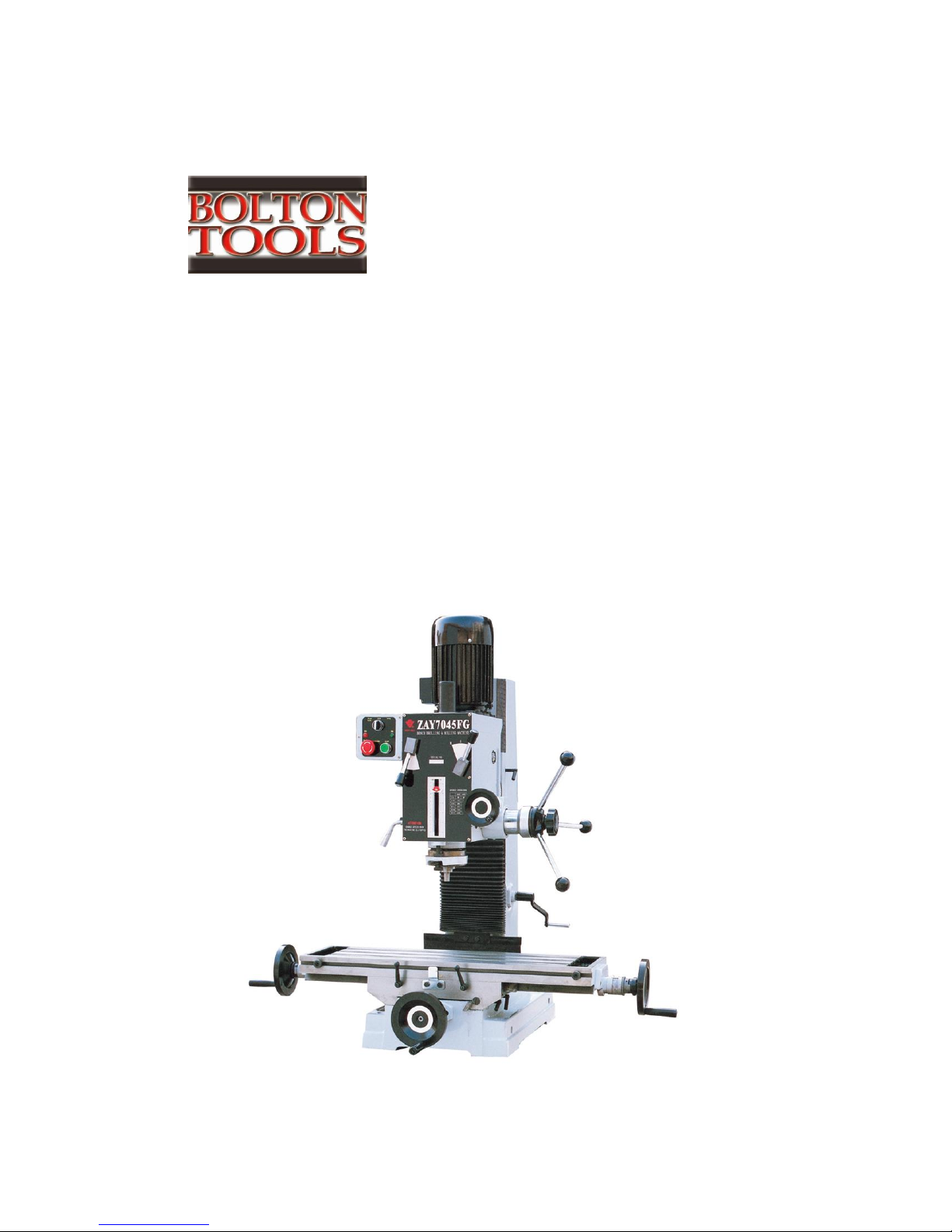
MODEL ZX45 PD
BENCH MILLING&DRILLING MACHINE
OPERATING MANUAL
Page 2

2
CONTENTS
SAFETY WARNING---------------------------3
SPECIFICATION----------------------------4
FEATURES---------------------------------5
INSTALLATION-----------------------------6
OPERATION--------------------------------6
ELECTRICAL SYSTEM------------------------9
TROUBLE SHOOTING-------------------------10
MAINTENANCE------------------------------12
Page 3

3
SAFETY WARNING
1. READ ALL INSTRUCTIONS BEFORE USING THIS MACHINE
2. KEEP GUARDS IN PLACE AND IN WORKING ORDER
3. KEEP WORK AREA CLEAN, CLUTTERED AREA INVITE INJURIES
4. KEEP CHILDREN AND VISITORS AWAY FROM WORK AREA
5. DRESS PROPERLY, NO LOOSE CLOTHING, GLOVES NECKTIES,OR
OTHER JEWELRY TO GET CAUGHT IN MOVING PARTS,WEAR
PROTECTIVE HAIR COVERING TO CONTAIN LONG HAIR.
6. ALWAYS WEAR EYE PROTECTION, ALSO USE FACE OR DUST MASK
IF OPERATION IS DUSTY.
7. REMOVE ADJUSTING KEYS AND WRENCHES FROM TOOL BEFORE
STARTING.
8. BE SURE DRILL BIT OR CUTTING TOOL IS SECURELY LOCKED IN
THE CHUCK.
9. AVOID UNINTENTIONAL STARTING
10. KEEP PROPER FOOTING AND BALANCE AT ALL TIMES,DO NOT
REACH OVER OR ACROSS RUNNING MACHINES.
11. MAINTAIN TOOLS WITH CARE, KEEP TOOLS SHARP AND CLEAN
FOR BETTER AND SAFER PERFORMANCE
12. DO NOT OPERATE THIS MACHINE WHILE THE INFLUENCE OF
DRUG, ALCOHOL OR ANY MEDICATION
13. USE THE RIGHT TOOL FOR THE JOB.DO NOT ATTEMPT TO FORCE
A SMALL TOOL OR ATTACHMENT TO DO THE WORK OF A LARGER
INDUSTRIAL TOOL.
14. ENSURE THIS MACHINE IS PROPERLY GROUNDED
15. SECURE WORKPIECE TO KEEP WORKPIECE FROM ROTATING
WITH THE DRILL BIT OR CUTTING TOOL
Page 4
4
SPECIFICATION
Model
ZX45 PD
Max.drilling capacity
1 7/9″
Max.face mill capacity
3 1/7″
Max.end mill capacity
1 1/9″
Max.tapping capacity
M12
Max.spindle stroke
5 1/8″
Max.distance from spindle axis to
column
10 1/4″
Swivel angle of headstock at
perpendicular direction
±90°
Max.distance between spindle nose
to table
17 5/7″
Spindle taper
M.T.4 OR R8
Working area of table
27 5/9″×9 4/9″or 31 1/2″×9 4/9″
Forward and backward travel of
table
6 8/9″
Left and right travel of table
15 3/4″ or 19 2/3″
Spindle speeds (4P)
50HZ: 80,145,260,375,710,1250 RPM
60HZ: 95,175,310,450,850,1500 RPM
Motor
1.5KW (1HP)
Length
32 2/7″
Width
41 3/4″ or 45 2/3″
Overall height (without stand)
40 1/6″
Net weight/gross weight
325kg/375kg
Standard accessories
Double end Wrench
Allen wrench 1/8″,1/6″, 1/5″,1/4″
Screwdriver(-)6″
Drill stock
Wedge
Drawbar
Drawbar washer
Page 5
5
FEATURES
(1) This machine may be used for surface cutting, drilling, milling, and
tapping.
(2) This machine is of fine quality, can be operated easily, it is not limited
to skilled operator.
(3) The drilling and milling operation can be performed by two methods:
1)Hand operation, which makes quick feeding drilling.
2)Worm gear feed operation, which makes slow feeding milling.
(4) Many of the adjustable nuts are bronze, for adjusting thread clearance
and reducing wear. These bronze parts also allow screws to rotate smoothly
and improve accuracy.
(5) The vertical column is very strong and stiff, which makes the machine
very stable and improves accuracy of manufactured parts.
(6) The machine headstock is cast iron, it has been heat-treated,
stress-relieved, and precision machined.
(7) Machine gears are precision ground for smooth operation.
(8) Speeds can be easily changed.
(9) Tapping can be done in either rotation; working depth can be controlled
by using a positive stop gauge.
(10)The head can be turned in two rotation for a satisfying desired angle.
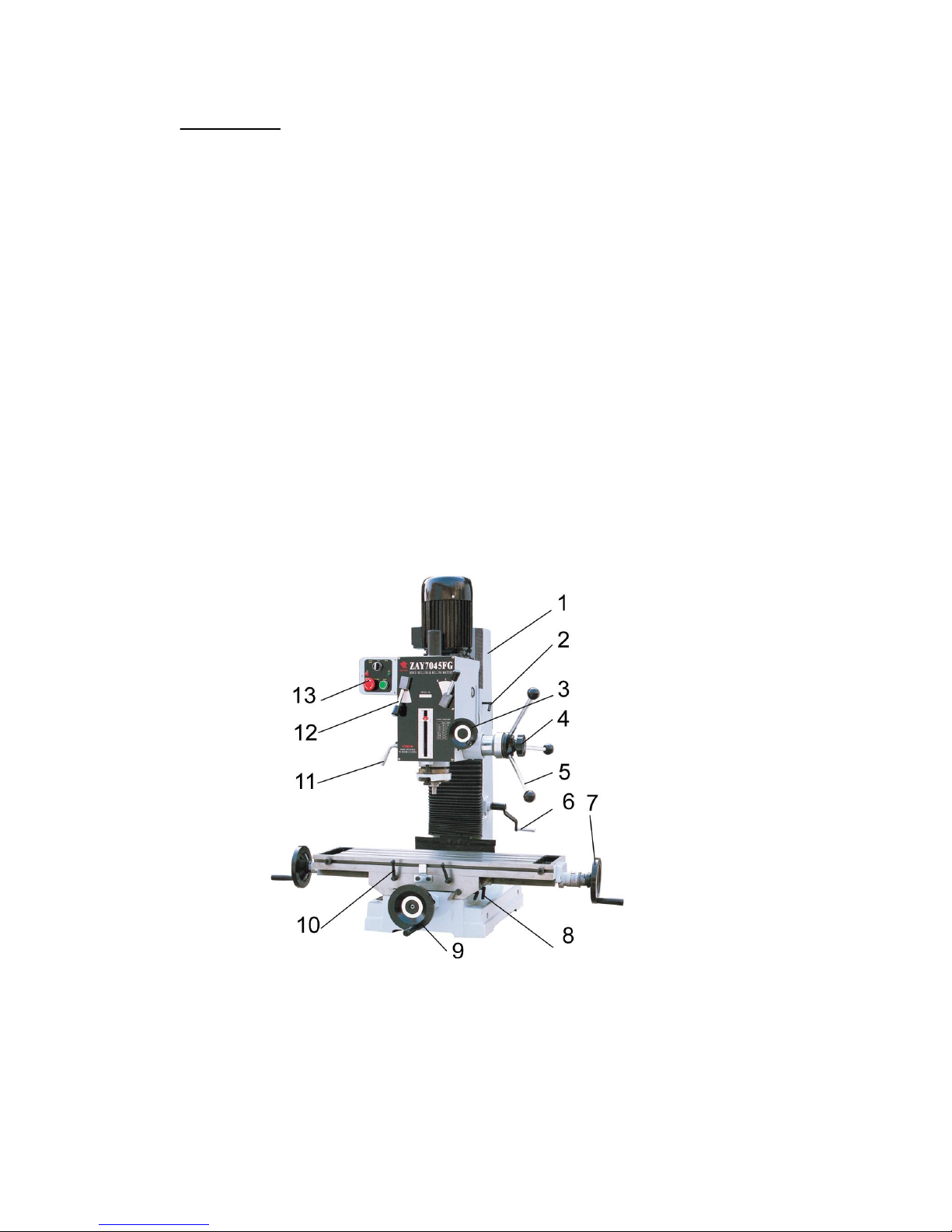
1. Square column 2.Lock screw 3.Micro feed handwheel
4. Lock handle 5.Feed handle 6.Crank 7.Handwheel
8. Cross lock screw 9. Longitudinal lock screw 10.Lock handle
11.Shift handle 12.Change speed handle 13.Switch
Page 6
6
INSTALLATION
(1) Ensure the headstock is as lower as possible, and be fixed on the column
tightly before moving machine. While moving machine, keep its balance
and safety.
(2) Don’t mount the machine at the sunshine place to avoid the deformity of
machine and the loss of accuracy .
(3) Mount machine to a sturdy table
or a solid concrete foundation, it’s advisable that the base you choose
be well constructed to avoid any vibration during operation.
(4) Thoroughly clean the machine with a commercial degreaser, and then coat
all bright metal with a light lubricant to prevent corrosion.
(5) Level the surface of the worktable on both lengthwise and crosswise by
using a precision level.
(6) Remove the oil filler plug and fill the oil to the gear box until the
oil level reaches the middle of the oil fluid level indicator. Lubricate
all points
OPERATION
Notice: Check all parts and safety precautions for
proper condition before operation
1. Use of main machine parts
(1)Raise and lower the headstock on its rack and pinion mechanism by using
the head crank. When the desired height is reached, tighten the bolts
to avoid vibration.
(2)Head may be rotated 360°by loosening the same bolts mentioned above.
Adjust the head to the desired angle, and then tighten the heavy duty
head lock nuts.
(3)For auto-tapping electrical system, the knob is seated for MILLING
& DRILLING, TAPPING AND STOP. The mushroom head red push button for
emergency stop while milling and drilling, or reverse while tapping,
the green push button for starting.
(4)Feed the spindle using spindle feeding handle, micro feed the spindle
Page 7

7
using the spindle micro feeding handle
(5)Move the table from side to side by using the lengthwise table feed
wheel, and from front to back by using the cross table feed wheel.
(6)Adjust the positive depth stop gauge according to working depth.
(7)Adjust the scale size according to working need.
2. Drilling operation
(1)For drilling blind hole (which do not pass through the workpiece),turn
off the knob make loose the taper body of worm gear and spring base,
then adjust the positive depth stop gauge so that the distance from
the tip of the drilling bit to the end of the blind hole is equal to
the desired depth.
(2)For drilling pass hole (which pass through the workpiece), set the
positive depth stop gauge in its uppermost position.
3. Milling operation
(1)Adjust the positive stop depth gauge to its uppermost position
(2)Using the spindle feed handle, adjust the cutter to approximately the
correct height, turn off the knob make tighten the taper body of worm
gear and spring base.
(3)Set the working depth by using the micro feed handle.
(4) Lock the rack sleeve at the height with the fixed bolt.
(5) When milling in the table longitudinal, it is a good idea to lock
the across feeding table to ensure the accuracy of your work. To do this,
tighten the two screws located on the right side of the table base.
(6) When cross feeding milling, lock the longitudinal feeding travel,
do this by tightening the two screws on the front of the table base.
4. Tapping operation
(1)Loosen the knob in the center of the spindle feed handle.
(2)Adjust the positive depth gauge to the required position.
(3)The switch point to “tapping”. When tapping is overload, press down
the red emergency switch, and the spindle reverse, the taper turn out.
5. Adjustment
(1)Adjustable moveable fixed rings are mounted on the front of the table
to limit cross travel.
(2)Your machine is equipped with gib strip adjustment to compensate for
wear and excess slack on cross and longitudinal travel.
(3)Rotate the gib strip bolt slightly clockwise to tighten the gib trip.
Rotate it slightly counter-clockwise to loosen the gib trip.
(4)Adjust the gib trip bolt until very slight drag is felt when moving
the table.
6. Changing machine speed
(1)Turn the power off.
(2)To select the proper speed, move the speed lever to the desired position.
Page 8
8
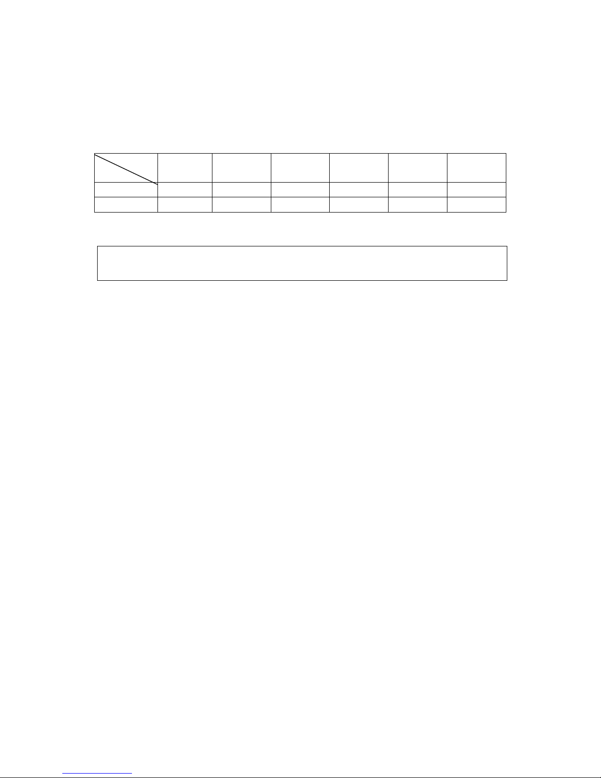
(3)If the gears are not engaged, remove the arbor bolt cover. Rotate the
spindle slightly to engage the gears, and then replace the arbor bolt
cover.
(4)Recheck the lever setting, and then turn the power on.
lever
RPM
Ⅰ-L
Ⅰ-M
Ⅰ-H
Ⅱ-L
Ⅱ-M
Ⅱ-H
50HZ
80
145
260
375
710
1250
60HZ
95
175
310
450
850
1500
7.Installing and changing tools
WARNING: BE SURE THE POWER IS TURNED OFF AND THE MACHINE
UNPLUGGED BEFORE INSTALLING OR CHANGING TOOL BITS.
(1)Removing face mill or drill chuck arbor.
Loosen the arbor bolt at the top of the spindle shaft approximately
2 turn with a wrench. Rap the top of the arbor bolt with a mallet. After
taper has been broken loose, holding chuck arbor on a hand and turn
the arbor bolt with the other hand.
(2)To install face mill or cutter arbor
Insert cutter and cutter arbor into the taper of spindle. Tighten arbor
bolt securely, but do not overtighten.
(3)Removing taper drills
(a) Turn down the arbor bolt and insert the taper drill into the spindle
shaft.
(b) Turn down the rack sleeve until the oblong hole in the rack sleeve
appears, lock the rack sleeve, insert wedge though holes and strike
lightly with a mallet, this will force the taper drill out.
8. Ordering replacement parts
Complete parts list is attached, if parts are needed, contact your local
distributor.
9. Additional tools and accessories you will find helping
Each machine is equipped with a M.T.3 or R8; contact your local
distributor or a main cutting tool distributor to obtain any of these
accessories.
Taper drills, Reamers, End mills, Cutter, Arbor, Taps, Collets, Adapters
and sleeves
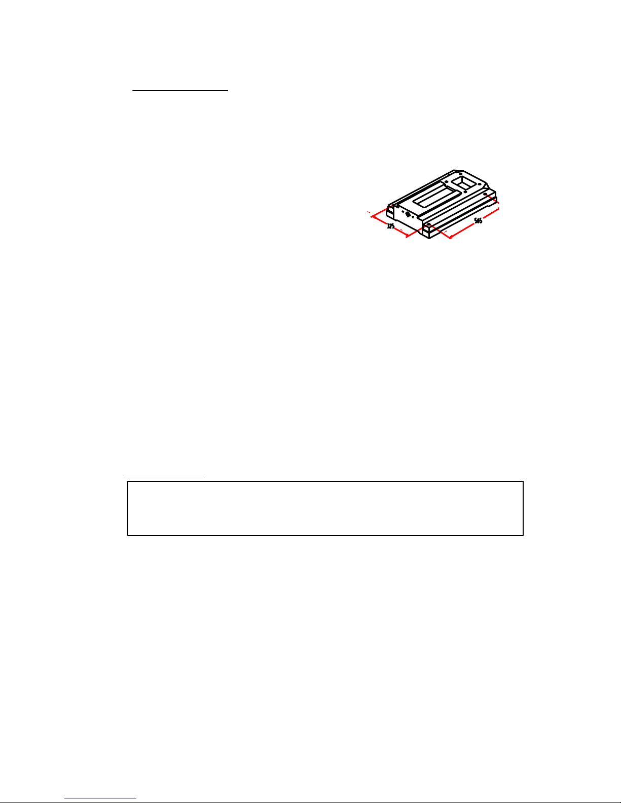
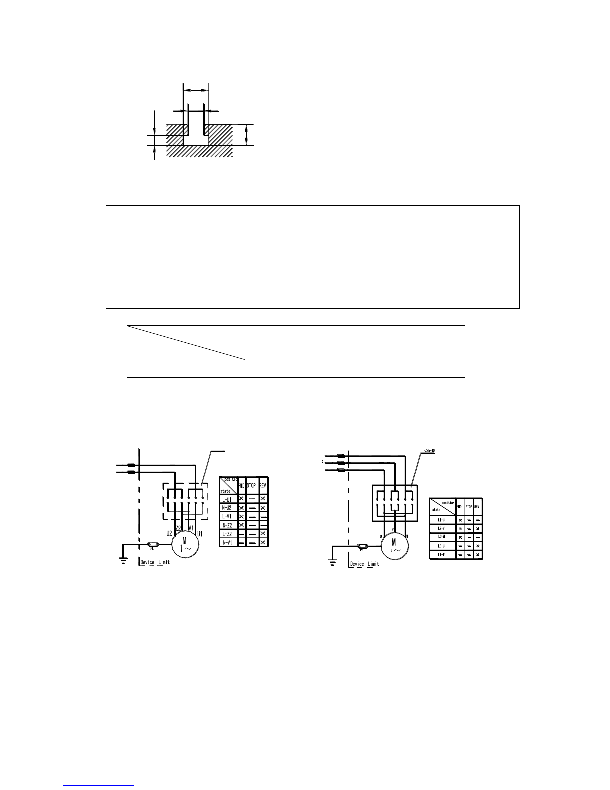
10. Specification of the T-slot
Please refer to figure. Purchase or make T-bolts and other table
top fixtures to these dimensions.
Page 9
9
16
10
21
26
ELECTRICAL SYSTEM
WARNING: 1.A fuse must be connected between machine and power.
2.The ground terminal of machine must be grounded
properly
3.Don’t open electrical box during operation, if
something is wrong with machine, please ask repairman
for help.
SPECIFICATIONS OF FUSE
Phase
Voltage
Single phase
Three phase
110V
30A
220V
15A
7.5A
380V 5A
For combination switch
L
N
HZZ5-10
Single phase Three phas
Page 10
10
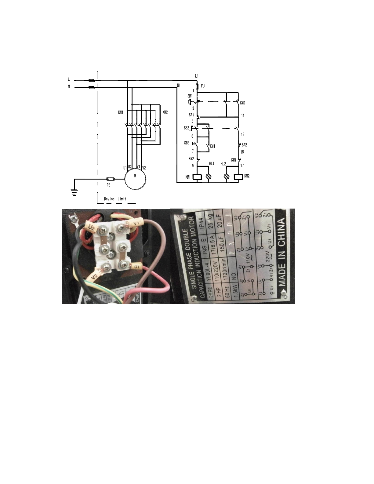
For auto-tapping electrical system
Single phase
Page 11
11
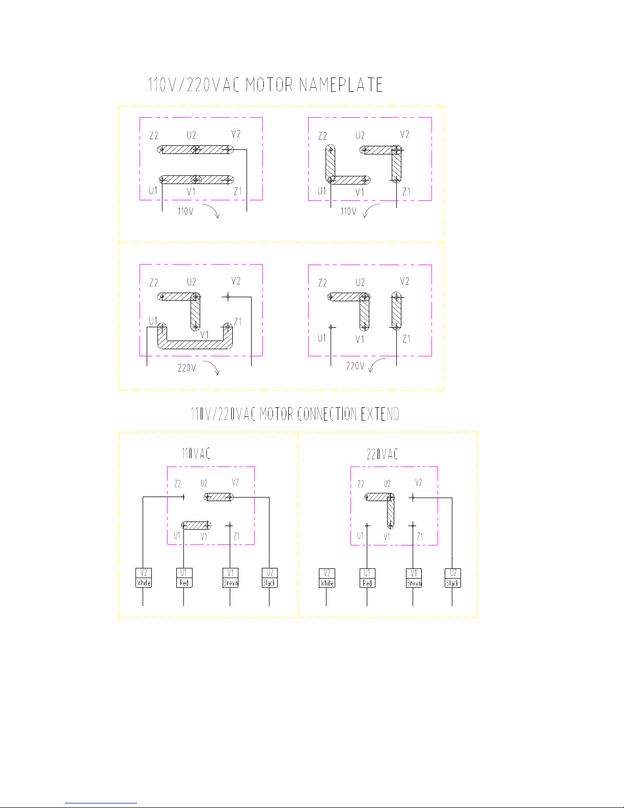
TAPE OFF V2 FOR 220 Volts
The standard wiring of the machine is single phase 220V/110V,
50HZ/60HZ or three phase 380V/220V,50HZ/60HZ.For special request,
Please refer to the wiring diagram in the addendum.
Page 12

12
TROUBLE SHOOTING
1. The machine doesn’t run when the power switch is turned ON
(a)The knob is in the STOP position
(b)A fuse has burned out---Check in the switch box, and replaces it
necessary.
(c)If there is a surge in the current, the circuit breaker may have
opened---Press the circuit breaker back, if it is in the open position.
(d)The gear may not be engaged---Adjust the speed lever to be sure it
is engaged.
2.The motor overheats, or there is insufficient power
(a)The machine is overloaded---Reduce the load of feed.
(b)The voltage supply is too low---provide with a reliable power
supply.
(c)The switch may have a burned or broken contact point---Replace the
switch.
(d)The contactor relay may be broken---Replace it.
(e)There may be a poor electrical connection. Have a qualified
electrician check the wiring and power supply.
(f)The motor is poor---replace with new one.
(g)The drill bit or cutting blade may be worn---Sharpen or replace
the bits as needed.
3. The spindle bearing is very hot.
(a)There is insufficient lubrication---Turn off the power and check
the bearing for lubrication. If necessary, apply bearing grease.
(b)The spindle bearing is worn, or is fixed too tight---Turn off the
power, unplug the electrical connection, and rotate the spindle
by hand. Be sure it freely. If not, adjustment the bearing .If you
feel no use in the bearing, you will have to replace it.
(c)The spindle has been turning at high speed for a long time---After
Long use, turn the machine off for a while to give it a rest, and
allow it to cool off.
4. Table travel is not balanced
(a) The gap of the table guide is too wide or feel a heavy drag when
moving the table---Adjust gib strip in proper
(b) The locked bolts may be loose---Check and tighten them if
necessary.
(c) The feed is too deep---Reduce the depth of cutting, make several
passes to reach the required depth.
5. There is vibration, and roughness of working surface
during performance.
(a)The gap of spindle bearing is too wide---Adjust the gap in proper
or replace bearing with new one.
(b)Spindle loosening up and down---Check the adjustment of the two
Page 13

13
inner bearing covers. Adjust them so there is no free play in the
taper bearing, and the bearing turns freely. Tighten them against
each other to save this adjustment.
(c)The gap of the taper sliding plate is too wide---Adjust the bolt
tension.
(d)The chuck is loose---Tighten the chuck.
(e)The drill bit or cutter is dull---Sharpen or replace it.be sure
to use cutting fluid to preserve tool life.
(f)The workpiece is not held firmly---Check the clamps or vise you
are using, and assure to tighten the workpiece
6. The micro feed does not work smoothly
(a)The clutch may be loose ---Check this and tighten if necessary.
(b)The worm or worm shaft may be worn---Check these and replace if
necessary.
(c)The handwheel fixed screw may be loose---Check it and tighten
if necessary.
7. The workpiece is not machined accurately
(a)Imbalance of heavy workpiece---Check to see that heavy workpiece
are held in balance. the workpiece Out of balance may shift when
being machined
(b)A hammer has been used on the workpiece---never strike the
workpiece with a hammer.
(c)The table may not be level---check the table with a level to be
sure it is level both side to side and front to back.
(d)The machine may not be stable in the floor--- be sure the machine
is firmly mounted to the floor.
MAINTENANCE
1. After each use
(a) Turn off the power switch.
(b) Remove any tool bits, clean and lubricate them, and return them
to their storage case.
(c) Using a stiff bristle brush, brush off all chips.
(d) Using a rag, wipe off any excess or dirty oil or cutting fluid
left on the machine.
(e) Lubricate the points, apply light grease or oil to all unpainted
metal to prevent corrosion.
(f) Cover the machine to prevent dust or dirt contamination when not
in use.
2. Daily maintenance
(a) Fill the oil reservoir to the proper level before each use
(b) Check the tightness of the bolts holding the head in place.
(c) If overheating or unusual noises are produced, stop the machine
Page 14

14
immediately to check for lack of lubrication, faulty adjustments,
dull tool bits or other deficiencies, correct any problems
before resuming work.
(d) Keep the work area clean.
3. Weekly maintenance
(a) Clean and coat the lead screw with oil.
(b) Check the lubrication of the sliding parts of the table. apply
light grease if needed.
4. Monthly maintenance
(a) Adjust the accuracy of the slides on both the cross and
longitudinal feeding.
(b) Lubricate the bearings, worm gear and worm shaft with light
grease.
5. Yearly maintenance
(a) Adjust the table to assure that it is level in all directions.
(b) Check the electrical cord, plug, circuit breakers and related
connections to assure that they are secure and safe.
(c) Drain the lubricant from the gear box and replace it.
Page 15
Page 16

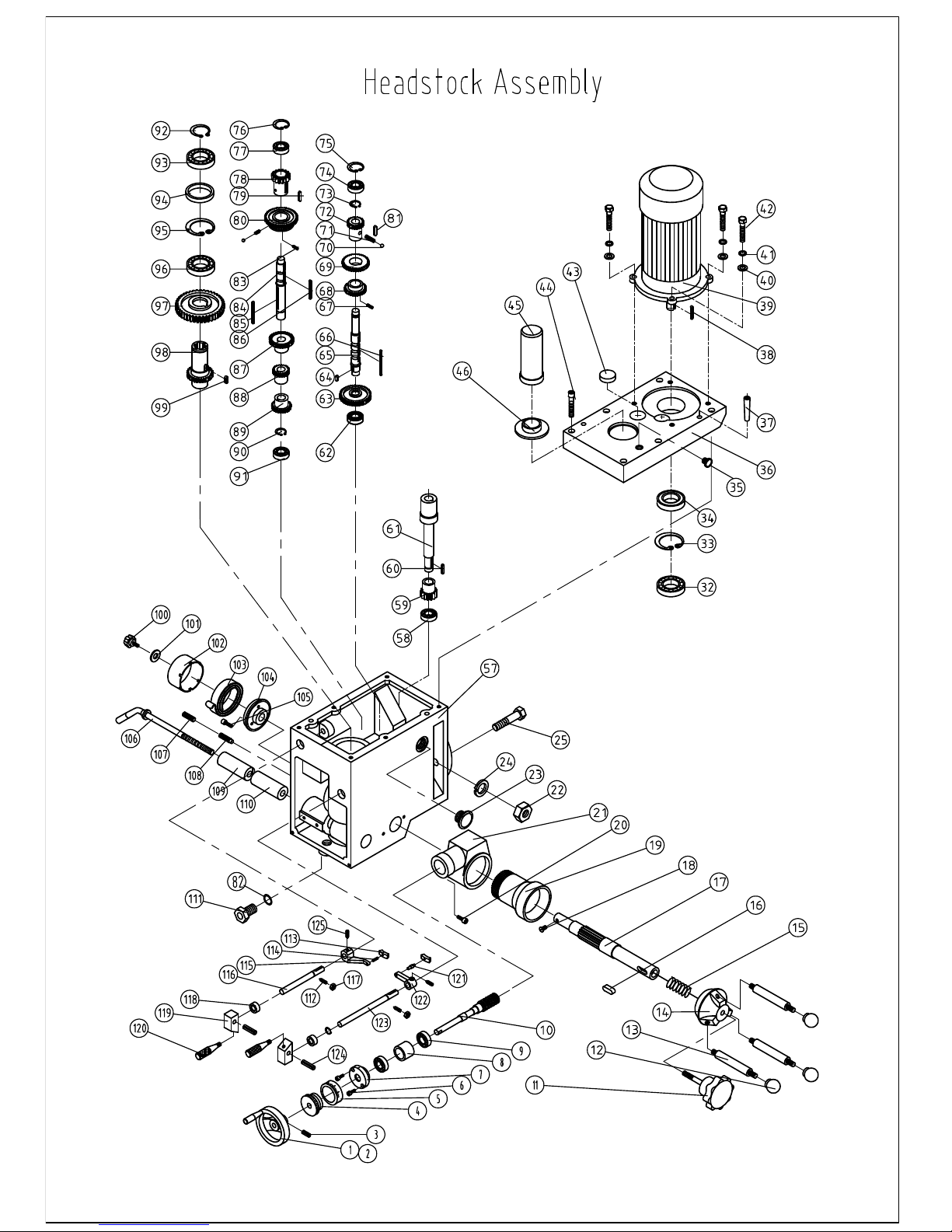
5
NO.
1
2
3
4
5
6
7
8
9
10
11
12
13
14
15
16
17
18
19
20
21
22
23
24
25
32
33
35
36
37
38
39
40
41
42
43
44
45
46
57
58
59
PART NO.
JB/T7273.2
JB/T7270.4
GB/T77-85
Zx32-05-002
ZX32-01-022
GB/T70-85
ZX32G-04-009
ZX32G-04-008
GB/T276-94
ZX32G-04-007
ZX32G-04-006
JB/T7271.1-94
JB/T7271.6-94
ZX32G-04-004
ZX32G-04-005
GB/T1096
ZX32G-04-001
GB/T818-85
ZX32G-04-003
GB/T70-85
ZX32G-04-002
GB/T6182-86
GB/T1160.2-89
GB/T93-87
GB/T5782-86
GB/T276-94
GB/T893.2-86
ZX32G-02-045
ZX32G-02-011
GB/T118-86
GB/T1096
GB/T95-85
GB/T93-85
GB/T5782-86
ZX32G-02-015
GB/T70-85
HQ400-24-021
ZX32G-02-013
ZX32G-02-001
GB/T276-94
ZX32G-02-022
DESCRIPTION
Handwheel 12×100
Handle M6×32
Screw M8×10
Dial seat
Dial
Screw M5×15
Cover
Bearing spacer
Bearing 6202
Worm shaft
Lock bolt with knob
Ball knob
Handle lever
Spring base
Spring
Key 8×22
Gear shaft
Screw M4×8
Worm
Screw M8×20
Feeding box
Lock nut M16
Fluid lever indicator
Spring washer
Bolt M16×60
Bearing 6007
Retain ring(external) B62
Oil filler plug
Head body cover
Taper pin 10×50
Key 6×35
Motor
Washer 10
Spring washer 10
Bolt M10×35
Cap
Screw M8×55
Arbor bolt cover
Arbor bolt cover base
Head body
Bearing 6003
Gear
QTY
1
1
1
1
1
6
1
1
2
1
1
3
3
1
1
1
1
1
1
2
1
2
1
2
2
3
2
1
1
2
1
1
4
4
4
2
6
1
1
1
3
1
Page 17

6
NO.
60
61
62
63
64
65
66
67
68
69
70
71
72
73
74
75
76
77
78
79
80
81
82
83
84
85
86
87
88
89
90
91
92
93
94
95
96
97
98
99
100
101
102
PART NO.
GB/T1096
ZX32G-02-023
GB/T276-94
ZX32G-02-017
GB/T1096
ZX32G-02-017
GB/T1096
GB/T73-85
ZX32G-02-020
ZX32G-02-019
GB/T308-84
GB/T2089-84
ZX32G-02-018
GB/T894.1-94
GB/T276-94
GB/T893.2
GB/T893.2
GB/T276-94
ZX32G-02-016
GB/T1096
ZX32G-02-014
GB/T1096
GB/T3452.1-82
GB/T73-85
ZX32G-02-003
GB/T1096
GB/T1096
ZX32G-02-006
ZX32G-02-005
ZX32G-02-004
GB/T894.1-86
GB/T276-94
GB/T894.2
GB/T276-94
ZX32G-02-012
GB/T893.2-86
GB/T276-94
ZX32G-02-010
ZX32G-02-009
GB/T1096
ZX32G-02-041
ZX32G-02-042
ZX32G-02-043
DESCRIPTION
Key 5×25
Shaft
Bearing 6003
Gear
Key 6×12
Shaft
Key 5×60
Screw M5×8
Gear
Gear
Steel ball 8
Spring
Gear
Inner ring 18
Bearing 6202
Retainer B35
Retainer B35
Bearing 6202
Gear
Key 6×15
Gear
Key 6×28
Gasket ring 9.8×2.65
Screw M5×8
Shaft
Key 6×75
Key 6×75
Gear
Gear
Gear
Retain ring (external) 18
Bearing 6202
Retain ring (external) 35
Bearing 6007
Spacer
Retain ring (internal) B62
Bearing 6007
Gear
Spindle sleeve gear
Key 6×18
Screw knob
Washer
Spring cover
QTY
1
1
1
1
1
1
1
1
1
1
2
2
1
2
3
1
1
1
1
1
1
1
1
1
1
1
1
1
1
1
1
1
1
1
1
1
1
1
1
1
1
Page 18

7
NO.
103
104
105
106
107
108
109
110
111
112
113
114
115
116
117
118
119
120
121
122
123
124
125
126
PART NO.
ZX32G-02-047
ZX32G-02-040
GB/T70-85
ZX32G-02-039
GB/T77-85
GB/T79-85
ZX32G-02-038
ZX32G-02-038
ZX32G-02-002
GB/T73-85
ZX32G-02-025
GB/T879-86
ZX32G-02-030
ZX32G-02-028B
GB/T894.1-86
GB/T9877.1
ZX32G-02-029A
ZX32G-02-029B
ZX32G-02-026
ZX32G-02-027
ZX32G-02-028A
GB/T879
GB/T70-85
JB/T7270.4
DESCRIPTION
Spring
Spring base
Screw M5×10
Lock handle
Screw M10×20
Screw M10×25
Fixed tight collar A
Fixed tight collar B
Lead screw
Screw M6×10
Fork
Spring pin 4×12
Lever
Lever shaft (short)
Retain ring (external) 12
Oil seal B12×22× 7
Handle base
Handle
Pin shaft
Fork
Lever shaft (long)
Spring pin 4×25
Screw M5×20
Handle taper M8×32
QTY
1
1
3
1
1
1
1
1
1
2
2
1
1
1
2
2
2
2
1
1
1
2
2
2
Page 19
Page 20

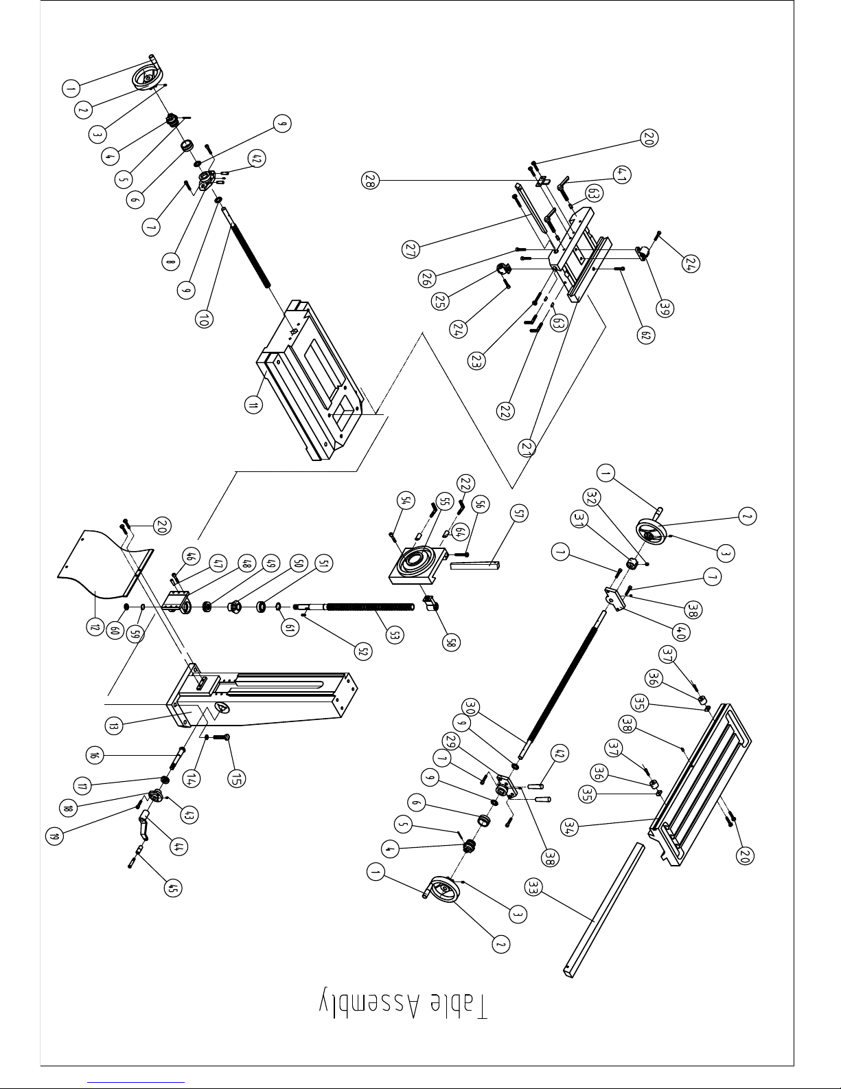
NO.
1
2
3
4
5
6
7
8
9
10
11
12
13
14
15
16
17
18
19
20
21
22
23
24
25
26
27
28
29
30
31
32
33
34
35
36
37
38
39
40
41
42
PART No.
GB/T7270.4
ZX32-01-028
GB/T77-85
ZX32-01-023
GB/T879-86
ZX32-01-022
GB/T70-85
ZX32-01-027
GB/T301-94
ZX32-01-024
ZX32-01-016
ZX32-01-010
ZX32W-01-004
GB/T-93-87
GB/T5780-86
ZX32W-01-008
GB/T301-94
ZX32W-01-009
GB/T70-85
GB/T5781-86
ZX32-01-015
ZX32-01-020
ZX32-01-004
GB/T70-85
ZX32-01-025
GB/T70-85
ZX32-01-019
ZX32-01-005
ZX32-01-002
ZX32-01-021
ZX32-01-014
GB/T77-85
ZX32-01-003
ZX32-01-001
ZX32-01-012
ZX32-01-011
GB/T70-85
JB/T7940.1
ZX32-01-026
ZX32-01-013
JB/T7270.12-94
GB/T118-86
Table Assembly
DESCRIPTION
Handle M10×80
Handwheel
Screw M6×10
Dial clutch
Spring pin 5×40
Dial ring
Screw M8×16
Square flange C
Thrust bearing 51103
Cross lead screw
Base
Anti-dust plate
Square column
Spring washer 16
Bolt M16×60
Tap gear shaft
Thrust bearing 511
Seat
Screw M6×20
Bolt M8×12
Middle base
Lock screw
Set screw
Screw M5×14
Cross nut
Screw M8×16
Gib (short)
Fixed bock
Square flange A
Longitudinal lead screw
Dial clutch
Screw M10×10
Gib (long)
Table
Moveable fixed block
Moveable fixed ring
Screw M6×12
Oil cup
Longitudinal nut
Square flange B
Adjusted set handle BM10×32
Taper pin 8×30
QTY.
3
3
3
2
2
2
6
1
4
1
1
1
1
4
4
1
1
1
3
2
1
4
2
1
1
2
1
1
1
1
1
1
1
1
2
2
2
5
1
1
2
4
Page 21

NO.
43
44
45
46
47
48
49
50
51
52
53
54
55
56
57
58
59
60
61
62
63
64
PART NO.
GB/T1155-79
ZX32W-01-018
GB/T7270.1-94
GB/T118-86
GB/T70-85
ZX32W-01-006
GB/T301-95
ZX32W-01-007
GB/T276-94
GB/T1096-79
ZX32W-01-005
GB/T70-85
ZX32W-01-001
ZX32W-01-014
ZX32W-01-003
ZX32W01-002
GB/T858-76
GB/T810-88
GB/T894.1-86
GB/T70-85
HQ400-11-015
ZX32W-01-013
DESCRIPTION
Oiler 6
Crank
Handle 6×63×12
Taper pin 8×30
Lock Screw M8×20
Bracket
Bearing 51103
Taper gear
Bearing 6204-2RS
Key 5×12
Lead Screw
Screw M8×40
Connective base
Adjustable screw
Gib
Lead nut
Stop washer
Nut M16×1.5
Retain ring (external) 20
Screw M8×45
Clamping incline block
Clamping incline block
QTY.
1
1
1
2
4
1
1
1
1
1
1
1
1
1
1
1
1
1
1
1
4
2
Page 22
Page 23

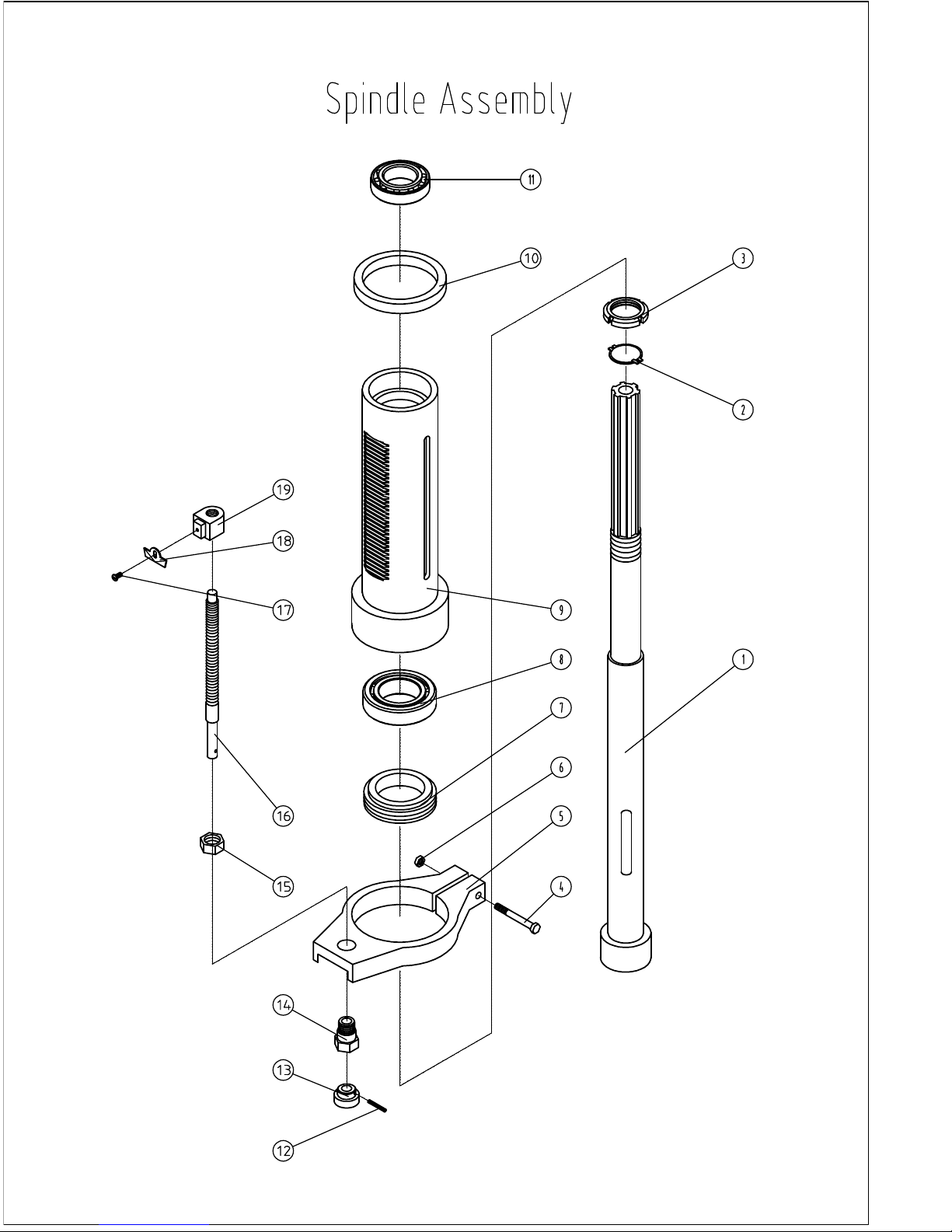
NO.
1
2
3
4
5
6
7
8
9
10
11
12
13
14
15
16
17
18
19
PART NO.
ZX40G-03-001
GB/T858-88
GB/T810-86
GB/T5780-86
ZX40G-03-003
GB/T41-86
ZX40G-03-002
GB/T297-94
ZX40G-03-005
ZX32G-03-004
GB/T297-94
GB/T879-86
ZX32G-03-010
ZX32G-03-009
GB/T6172-86
ZX32G-03-006
GB/T818-85
ZX32G-03-008
ZX32G-03-007
Spindle Assembly
DESCRIPTION
Spindle
Stop washer 30
Nut M30×1.5
Bolt M6×50
Graduate rod base
Nut M6
Anti-dust ring
Bearing 30208/P6
Rack sleeve
Rubber flange
Bearing 30206/P6
Spring pin φ3×18
Handle
Support
Thin nut M16
Graduate rod
Screw M4×6
Indicating plate
Set position block
QTY
1
1
1
1
1
1
1
1
1
1
1
1
1
1
1
1
1
1
1
 Loading...