

Page 1

MODEL Q01-1.5x1320(52”)
FOOT SHEARER
OPERATION MANUAL
Page 2

1. PRIOR TO INSTALLATION AND OPERATION
Read the following instruction carefully and thoroughly will ensure
your machine in perfect function and avoid possible dangers.
2. RECEIVING AND UNPACKING
On receiving your machine, examine if the other packing is in good
condition, Then, remove the cover to inspect whether there is any damage
or loss caused during transportation, If any is found, please immediately
notify the transportation any your supplier, Some parts and the
accessories are knocked down and in bulk packing to save transportation
space. You must check those parts and accessories in extra care. Then,
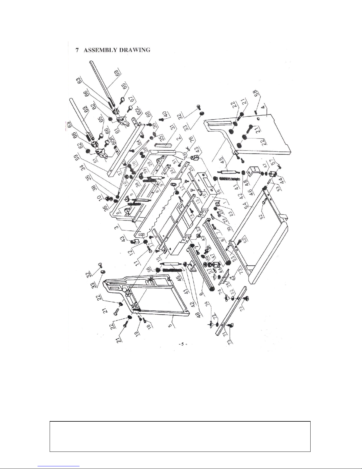
assemble them on to the machine according to the illustrations.
3. INSTALLATION
Be sure to install your shear on a solid lever floor. The work area
should he well lighted to prevent any wrong or danger in operation.
Fix the machine on to the floor with anchor bolts to prevent from
vibration. Place a precision level on the table surface to level the machine
in all direction. Insert metal shims between floor and the shear mounting
surface to adjust the level. Tighten all of the bolts after those being
adjusted.
4. CAUTIONS
The knives are sharp. Take extra care in operating, Keep hands away
from the reach of blade.
Page 3

Wear safety glasses or goggles to protect your eyes. Wear protective
type foot shear. Keep the work area clear and to avoid slipping or
tripping.
Never take away the protective guard. Keep hold down the learance to
the minimum gap required to feed material.
Never use shear to cut rod or material exceeding its designed capacity.
Never attempt to shear any material less than a 1/2″cut across the full
length of the table under full capacity.
5. OPERATION INSTRUCTION
The chart below is a material conversion comparison to show
equivalent capacities of material other than mild steel.
Model 37″ Model 52″
MILD STEEL GAUGE 1.0mm 1.5mm
ALUMINUM 1.8mm 2.5mm
BRASS YELLOW
SOFT 1.2mm 1.8mm
1/2HARD 1.1mm 1.6mm
HARD 1.1mm 1.6mm
NRONZE PHOSPHOR
ANNEALED 1.1mm 1.6mm
COPPER
SOFT 1.2mm 1.8mm
Page 4

HARD 1.1mm 1.6mm
PLASTIC ABS COMPOUND 1.8mm 2.5mm
5.2 BACK GAUGE ADJUSTMENT
On adjusting back gauge, loosen adjustment knobs, slide angle.
Remove rod forward or backward for scales to read zero on pointers.
Lock bracket again and do further an adjustment with wheel.
Tighten socket screws to lock rods in place.
5.3 BLADE CLEARANCE ADJUSTMENT
To adjust blade clearance, loosen front screws and table lock screws,
and loosen table bolts on both sides.
Use a 0.002″slim gauge and adjust table lock screws. Then, tighten
all screws. (See Figure 1).
5.4 CUTTER HEAD ADJUSTMENT
If cutter head is bowed after use. You can adjust the bow bolt. Check
for looseness of mounting bolt. Re-tighten all bolts. (See Figure 2).
To adjust the blade up or down. Drop pin on treadle and loosen nut.
Adjust yoke up or down. Reassemble them.
Loose lock screws may cause shake of blade in operation.
Check and sure they are rightly against shims. But be careful not to
dimple them.
5.5 TO SHARPEN THE BLADE
The upper blade has two cutting edges what are ground with a 2 edges
Page 5
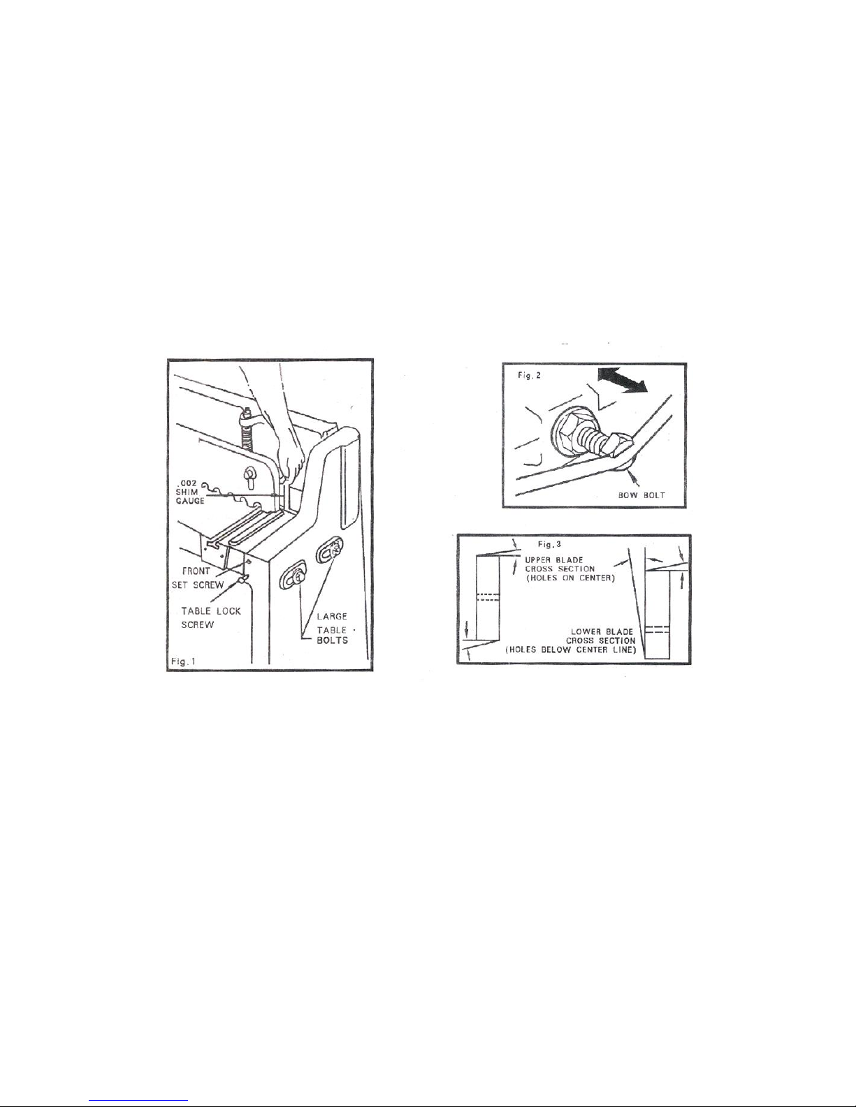
relief. Reverse to expose the new cutting edge as soon one edge is dull. It
can be sharpened on a surface grinder by grinder by grinding machine
both wide sides of the blade.
The lower blade has one cutting edge with a 2 edges relief and a 1
face relief. It can be re-sharpened on a surface grinder by grinding the
wide side of the blade having the 1 relief. (See Figure 3).
Page 6
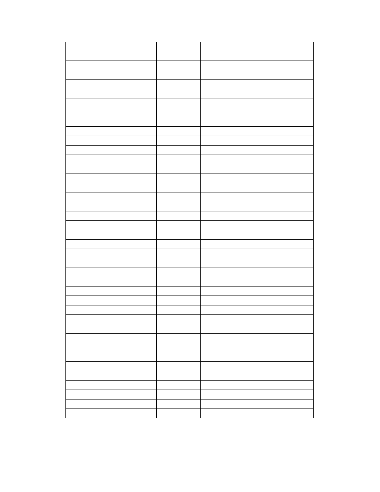
ITEM#
Description
Qty
Item#
Description
Qty
1
Work Table
1
39
Washer
1 2 Frame
1
40
Screw
2 3 Pressing plate
1
41
Spring
2 4 Right Stand
1
42
Washer
2 5 Left Stand
1
43
Upper Connecting Block
2 6 Connecting Rod
2
44
Lower Connecting Block
2 7 Screw
4
45
Bolt
2 8 Spring
2
46
Washer
2
29
Bolt
2
47
Nut 2 10
Nut 2 48
Connecting Plate
2
11
Screw
2
49
Bolt
4
12
Washer
2
50
Washer
4
13
Protecting Board
1
51
Upper Pin
2
14
Screw
3
52
Lower Pin
2
15
Workpiece Stop
2
53
Small Shaft
2
16
Gauge
2
54
Foot Stand Frame
1
17
Screw
4
55
Lid 2 18
Bolt
2
56
Pin 2 19
Bolt
2
57
Screw
2
20
Bolt
2
58
Workpiece stop
1
21
Bolt
2
59
Right Fixing Plate
1
22
Washer
4
60
Left Fixing Plate
1
23
Nut 4 61
Find Adjustment Stand
2
24
Upper Blade
1
62
Adjust Nut
2
25
Lower Blade
1
63
Bolt Shaft
2
26
Screw
8
64
Bolt
2
27
Screw
9
65
Small Screw
2
28
Washer
8
66
Large Screw
1
29
Washer
9
67
Large Screw
1
30
Screw
4
68
Bolt
2
31
Sliding Plate
2
69
Gauge Shaft
2
32
Screw
6
70
Nut 1 33
Nut
6
71
Workpiece Pushing Plate
1
34
Surengthening Rod
1
72
Washer
3
35
Washer
2
73
T-style Bolt
3
36
Nut 2 74
Wing Nut
3
37
Adjusting Bolt
1
75
Small Workpiece Pushing Plate
1
38
Washer
2
76
Pin
2
Page 7
Note: This manual is only for your reference. Owing to the continuous improvement
of the machine, changes may be made at any time without obligation on notice.
 Loading...