

Page 1
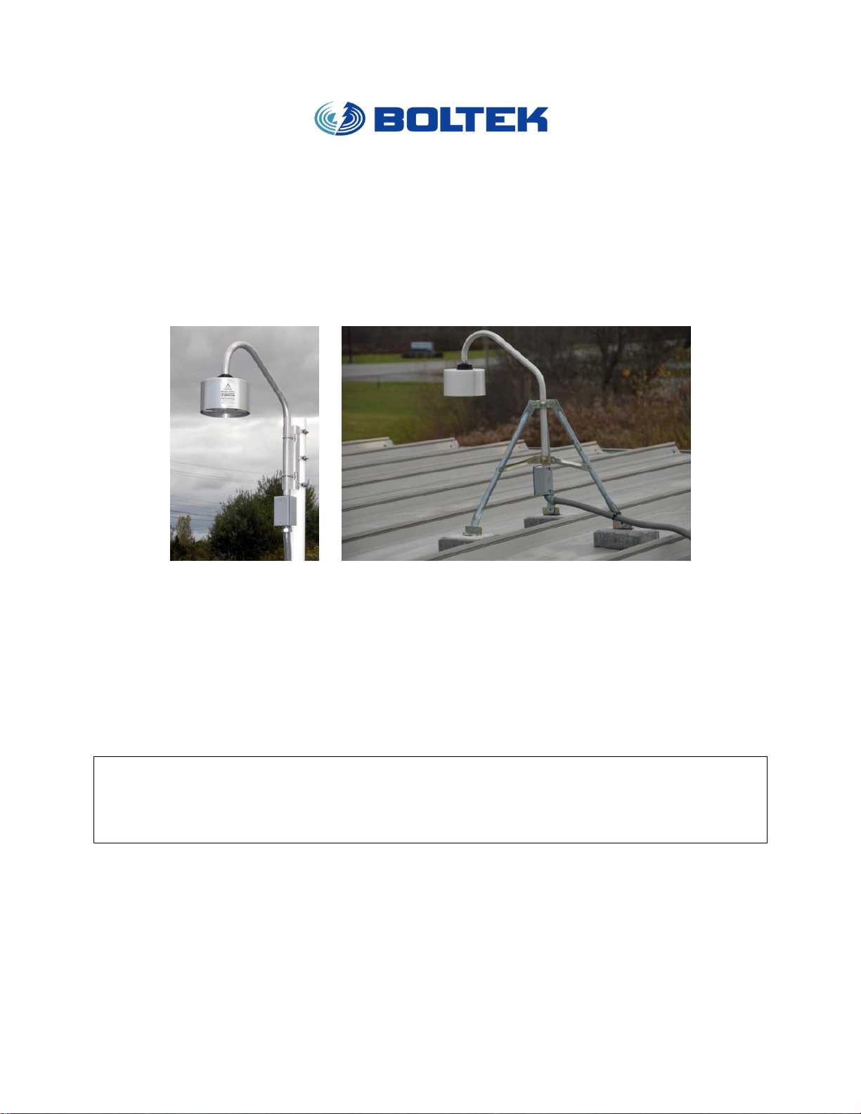
Boltek EFM-INV-M / EFM-INV2 / EFM-INV3
Inverting Mounting Kit
Installation Instructions
10/10/2012
Introduction
The EFM-INV-M, EFM-INV2, and EFM-INV3 Inverted Mounting Kits will allow you to mount your EFM-100 or EFM200 Electric Field Mill in the inverted downward-facing configuration. Inverting your field mill will provide you with
reduced precipitation noise.
ELECTROCUTION WARNING:
INSTALLATION THIS PRODUCT NEAR POWERLINES IS DANGEROUS.
FOR YOUR SAFETY, FOLLOW THE INSTALLATION DIRECTIONS.
SEE ADDITIONAL WARNINGS ON REVERSE
(C) 2012 BOLTEK CORP EFM-INV_Instruction_1.2
Page 2

10/10/2012
Warning Do not locate the sensor near overhead power lines or other electric light or
power circuits, or where it can come into contact with such circuits. When installing the
sensor, take extreme care not to come into contact with such circuits, as they may cause
serious injury or death. For proper installation and grounding of the sensor, please refer to
national and local codes (e.g. U.S.:NFPA 70, National Electrical Code, Article 810, in
Canada: Canadian Electrical Code, Section 54).
ELECTROCUTION WARNING:
INSTALLATION OF THIS PRODUCT NEAR POWERLINES IS DANGEROUS.
FOR YOUR SAFETY, FOLLOW THE INSTALLATION DIRECTIONS.
FALL WARNING:
DO NOT ATTEMPT INSTALLATION AT HEIGHTS UNLESS YOU ARE EXPERIENCED
IN THE SAFE USE OF LADDERS AND FALL ARRESTING EQUIPMENT. IF UNSURE
REFER INSTALLATION TO AN EXPERIENCED ANTENNA OR SATELLITE INSTALLER.
LIGHTNING ACTIVITY WARNING:
DO NOT WORK ON THE SYSTEM OR CONNECT OR DISCONNECT CABLES DURING
PERIODS OF LIGHTNING ACTIVITY.
Installation and Grounding Warning
Document Revision History
1.0 2009 Original document
1.1 07/31/2011 Added instructions to apply silicone grease to threads and washer
(C) 2012 BOLTEK CORP EFM-INV_Instruction_1.2
Page 3
Contents of the Kit
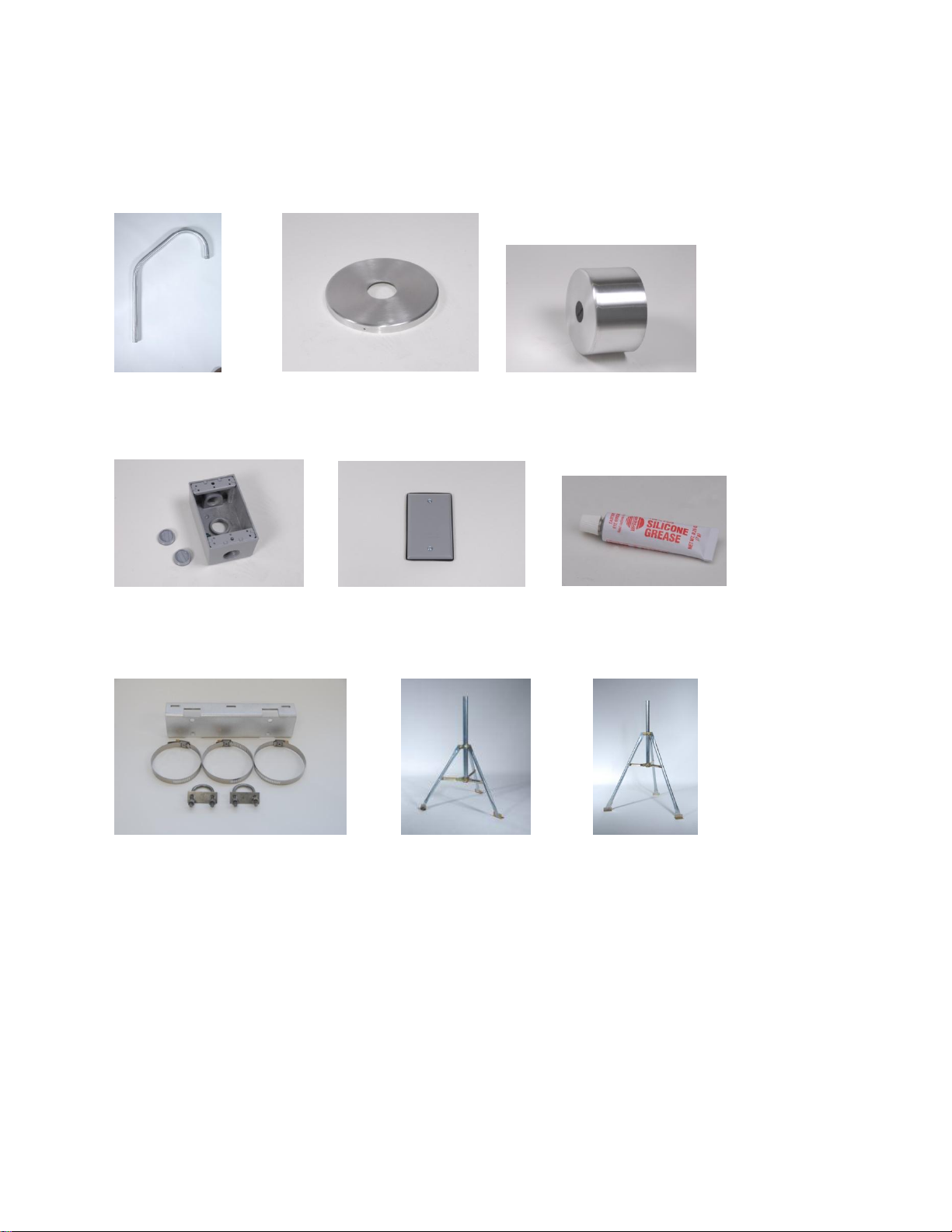
Your EFM-INV-M (Pole mount bracket), EFM-INV2 (2 foot tripod) or EFM-INV3 (3 foot tripod)
kit should include the following items:
Inverting Mast Inverted Cover Shroud
10/10/2012
Junction Box Junction Box Cover Silicone Grease
Pole mount bracket (EFM-INV-M) or 2' Tripod (EFM-INV2) or 3' Tripod (EFM-INV3)
with clamps & bolts
(C) 2012 BOLTEK CORP EFM-INV_Instruction_1.2
Page 4
10/10/2012
Choosing a Mounting Location
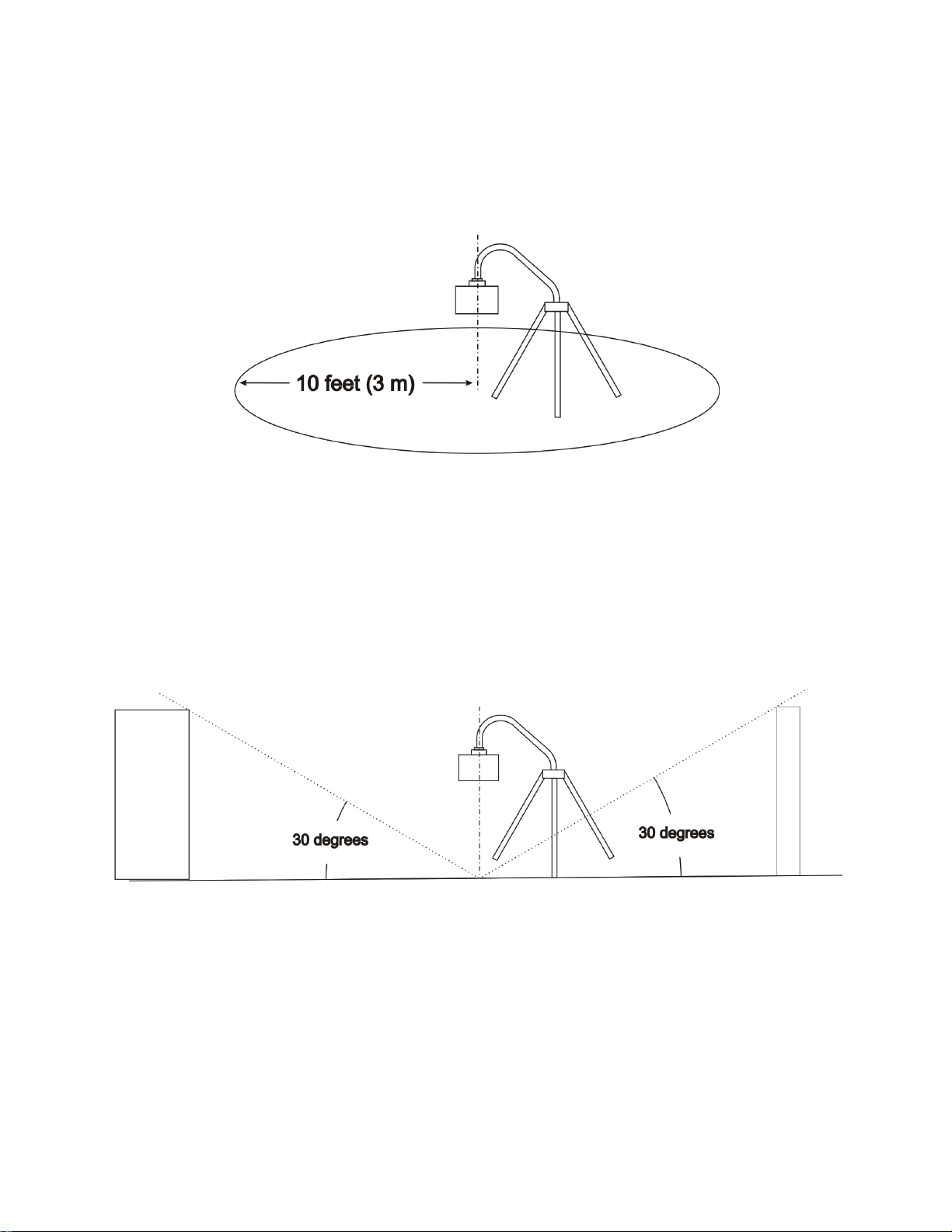
Choosing a suitable mounting location is the single most important aspect of a successful installation.
KEEP CLEAR AREA
Persons or animals entering the Keep Clear Area may be detected by the field mill as a High Electric Field
or Lightning. If the field mill is mounted at ground level a fence or other barrier should be erected
around the field mill. Keep the area directly under the field mill clear of long grass or weeds. Patio slabs
or a poured concrete pad is recommended for ground installations.
FIELD OF VIEW
The electric field mill requires a view of the sky to detect the static charge on overhead clouds.
Obstructions within the field mills field of view may reduce the sensitivity of the field mill
Secure the tripod to the roof or patio slabs/concrete pad on the ground. For a no-holes tripod
installation on a flat roof the tripod may be secured to patio slabs placed on the roof. Run cables away
from the field mill sensor, not directly underneath.
(C) 2012 BOLTEK CORP EFM-INV_Instruction_1.2
Page 5
10/10/2012
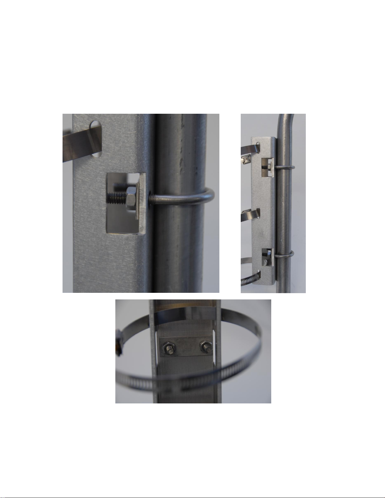
Assembling the pole mount bracket
(Skip this page if using INV2 or INV3 kit)
Remove nuts and washers from the two U-Bolts and place around inverted mast. Secure bolts
to bracket as shown below
Open hose clamps, and hold bracket against pole. Place hose clamps through bracket and
tighten around pole. Recommended pole size is between 2.5" and 4" outer diameter. If a larger
pole is used, bigger hose clamps can be purchased at a local hardware store.
(C) 2012 BOLTEK CORP EFM-INV_Instruction_1.2
Page 6
Assembling the hardware
10/10/2012
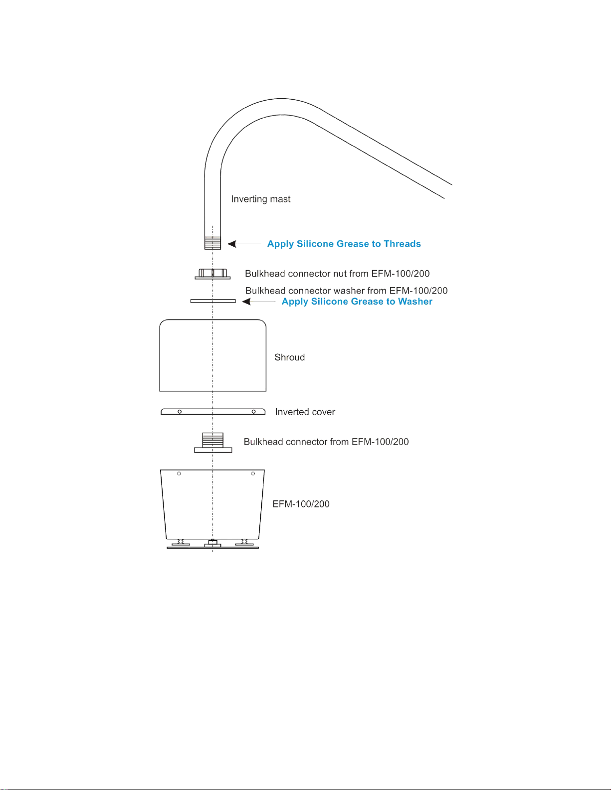
EXPLODED VIEW OF ASSEMBLY
COAT THREADS AND RUBBER WASHER WITH SILICONE GREASE.
RUBBER WASHER MUST BE LOCATED BETWEEN NUT AND SHROUD.
FAILURE TO PROPERLY INSTALL WASHER WILL RESULT IN WATER DAMAGE TO FIELD MILL
NOT COVERED BY WARRANTY
(C) 2012 BOLTEK CORP EFM-INV_Instruction_1.2
Page 7
10/10/2012
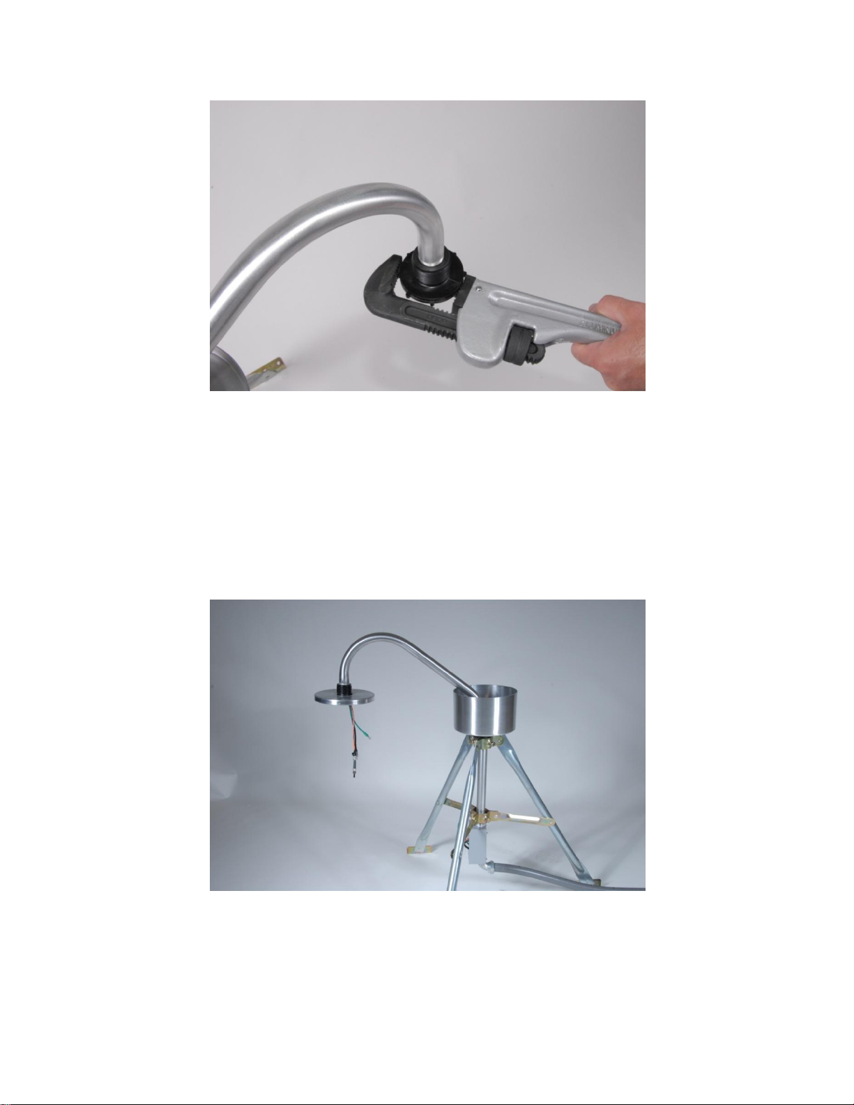
PIPE WRENCH TIGHTENING BULKHEAD ONTO MAST (HAND TIGHT +4 TURNS WITH WRENCH)
COAT PIPE THREADS WITH SILICONE GREASE.
FAILURE TO PROPERLY TIGHTEN BULKHEAD ONTO MAST WILL RESULT IN WATER DAMAGE
TO FIELD MILL NOT COVERED BY WARRANTY
READY FOR THE FIELD MILL TO BE CONNECTED
REFER TO THE EFM-100/200 DOCUMENTATION FOR DETAILS ON CONNECTING AND
GROUNDING YOUR FIELD MILL
(C) 2012 BOLTEK CORP EFM-INV_Instruction_1.2
Page 8
10/10/2012
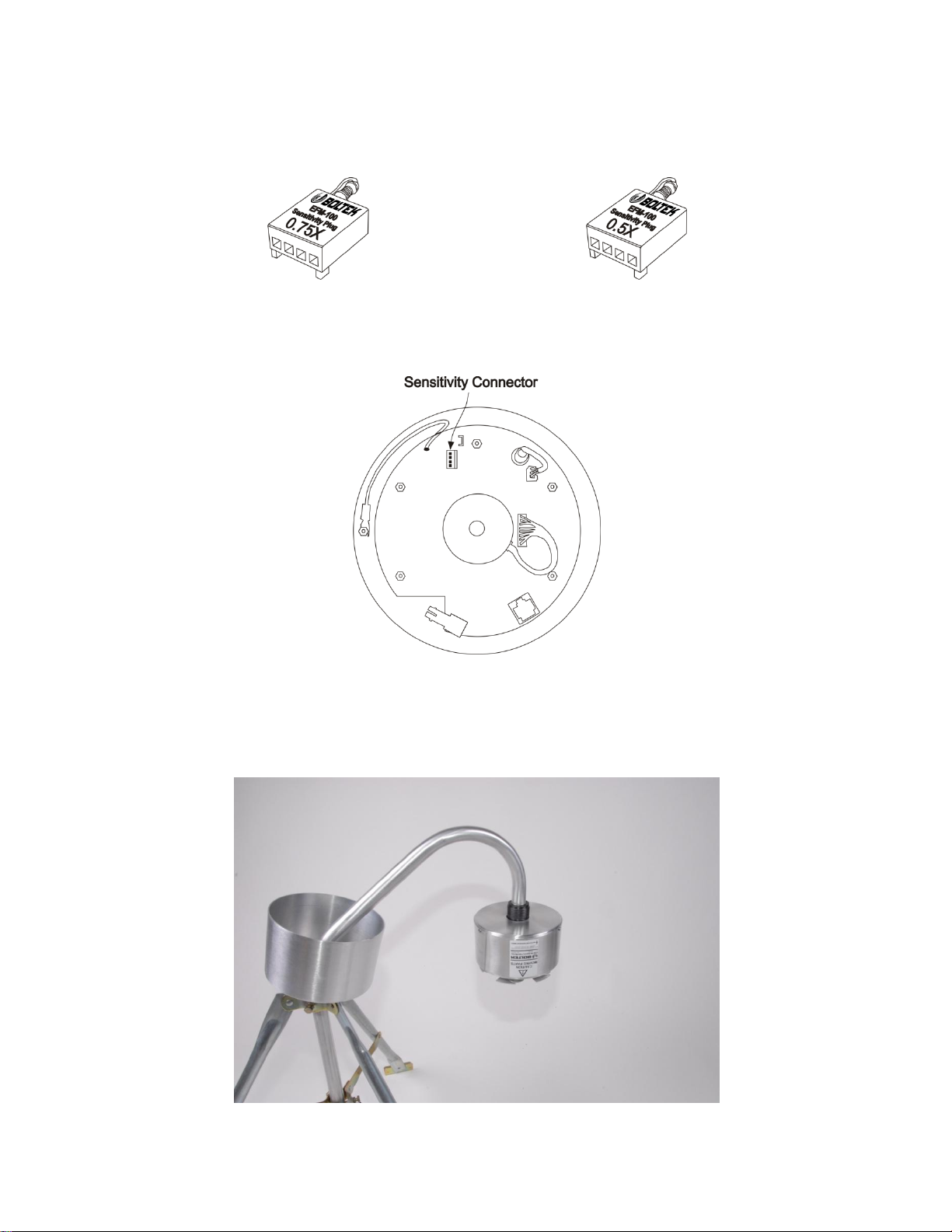
EFM-INV2 USE 0.75X EFM-INV3 USE 0.5X
INSTALL THE APPROPRIATE SENSITIVITY PLUG BEFORE CONNECTING FIELD MILL
(C) 2012 BOLTEK CORP EFM-INV_Instruction_1.2
Page 9
10/10/2012
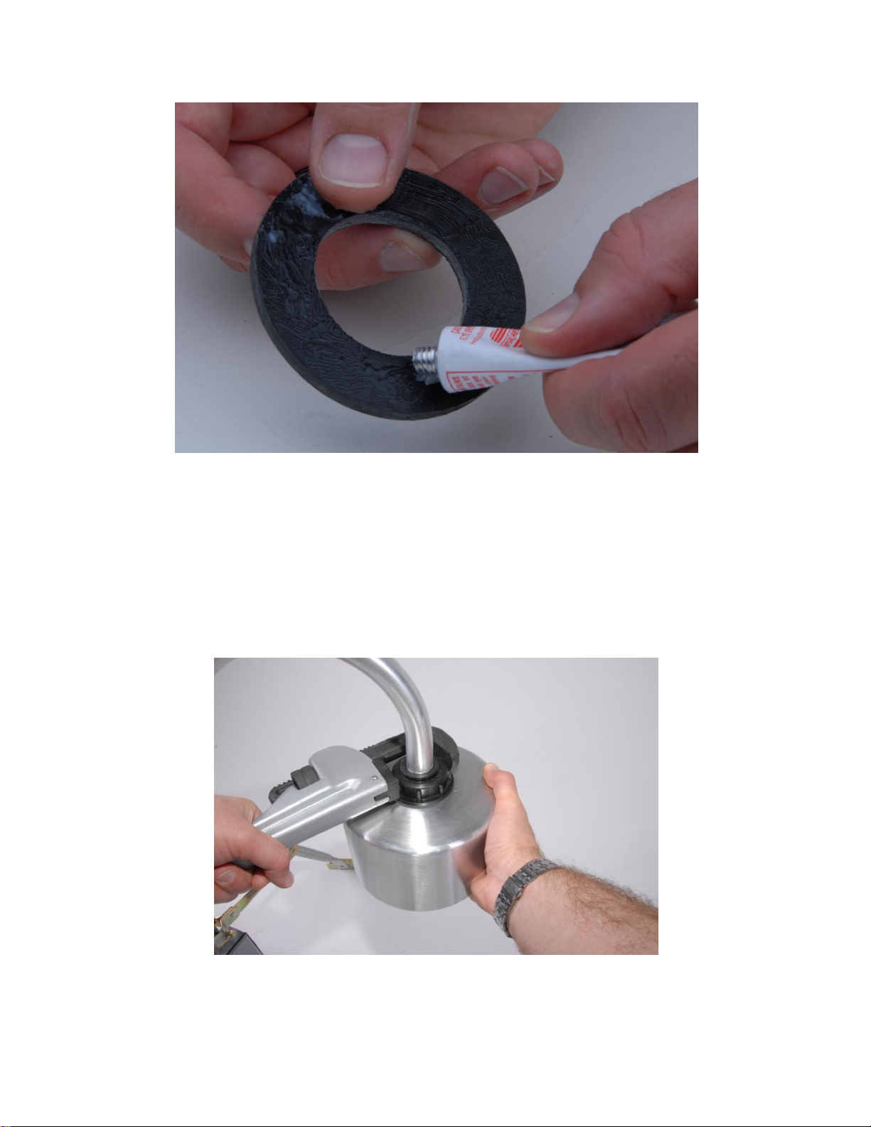
COAT BOTH SIDES OF THE RUBBER WASHER WITH SILICONE GREASE
Connect Power, Ground and Fiber Optic connectors, then screw the Field Mill to its cover. Lower the
Shroud over the Field Mill. Lower the greased rubber washer onto Bulkhead Connector, and then the
Bulkhead Nut. Tighten the Bulkhead Nut until the Rubber Washer is visibly compressed.
PIPE WRENCH TIGHTENING NUT ONTO RUBBER WASHER
(NOTE: LEFT-HANDED COUNTER-CLOCKWISE THREAD ON NUT )
(C) 2012 BOLTEK CORP EFM-INV_Instruction_1.2
Page 10
10/10/2012
DO NOT ALLOW FIELD MILL TO ROTATE OR WIRES CONNECTING FIELD MILL WILL TWIST
COAT BOTH SIDES OF RUBBER WASHER WITH SILICONE GREASE.
FAILURE TO PROPERLY TIGHTEN NUT ONTO RUBBER WASHER AND SHROUD WILL RESULT IN
WATER DAMAGE TO FIELD MILL NOT COVERED BY WARRANTY
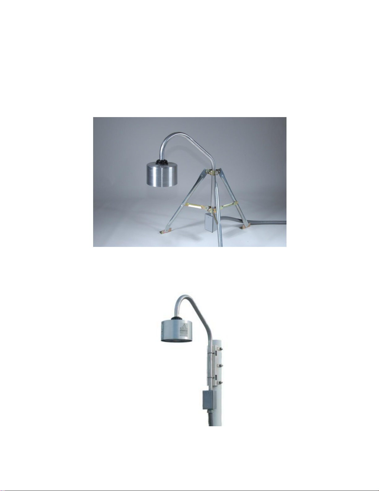
COMPLETED ASSEMBLY (with 2' tripod)
COMPLETED ASSEMBLY (with pole mount bracket)
(C) 2012 BOLTEK CORP EFM-INV_Instruction_1.2
 Loading...