

Page 1
BOLTEK CORPORATION
Lightning Detection
GSM-1 Text Message Notification
for EFM-100C Electric Field Monitor
User Guide
SEE DISCLAIMER ON REVERSE
Page 2

B O L T E K LIG H T N I N G D E T E C T I O N
GSM-1 Text Message Alert Dialer
Disclaimer
Lightning data is only approximate and should not be used for safety applications. Strike and storm
locations indicated and alarm statuses may be erroneous and should not be used to safeguard personnel,
equipment or data.
Neither Boltek Corporation nor its affiliates shall be liable to the purchaser of this product or third parties
for damages, losses, costs, or expenses incurred by purchaser or third parties as a result of use, misuse,
accident, or abuse.
Notwithstanding the above Boltek Corp’s liability shall not exceed the purchase price of the equipment.
THIS EQUIPMENT IS NOT TO BE USED FOR SAFETY PURPOSES
©2017 Boltek Corporation
Boltek Corporation
4 Stonebridge Dr. Unit 2
Port Colborne, ON L3K5V5
Canada
Email: [email protected]
Web: www.boltek.com
Phone (905) 734-8045 • Fax (905) 734-9049
Page 3
FCC Compliance Statement
For United States Users
This equipment is tested and found to comply with the limits for a Class B digital device, pursuant to Part 15 of
the FCC Rules. These limits are designed to provide reasonable protection against harmful interference in a
residential installation. This equipment generates, uses, and can radiate radio frequency energy and, if not installed
and used in accordance with the instructions, may cause harmful interference to radio or television reception.
However, there is no guarantee that interference will not occur in a particular installation. If this equipment does
cause interference to radio and television reception, which can be determined by turning the equipment on and off,
the user is encouraged to try to correct the interference by one or more of the following measures.
• Reorient or relocate the receiving antenna.
• Increase the separation between the equipment and the receiver.
• Connect the equipment into an outlet on a circuit different from that to which the receiver is connected.
• Consult the dealer or an experienced radio/TV technician for help.
WARNING
The connection of a non-shielded equipment interface cable to this equipment will invalidate the FCC Certification
of this device and may cause interference levels which exceed the limits established by the FCC for this equipment.
It is the responsibility of the user to use a shielded interface cable with this device. If this equipment has more than
one interface connector, do not leave cables connected to unused interfaces. Changes or modifications not
expressly approved by the manufacturer could void the user’s authority to operate the equipment.
For Canadian Users
This Class B digital apparatus meets all requirements of the Canadian Interference-Causing Equipment
Regulations.
Cet appareil numérique de la class B respecte toutes les exigences du Règlement sur le materiel brouilleur du
Canada.
WARNING: LIGHTNING AND ELECTRIC FIELD DATA IS ONLY APPROXIMATE
AND SHOULD NOT BE USED FOR SAFETY APPLICATIONS. ELECTRIC FIELD
READINGS, STRIKE DISTANCES AND ALARM STATUSES MAY BE ERRONEOUS
AND SHOULD NOT BE USED AS A PRIMARY MEANS TO SAFEGUARD PERSONS,
EQUIPMENT OR DATA.
Page 4

Table of Contents
Introduction ......................................................................................... 1
Installing SIM Card ............................................................................ 2
Setup Instructions ............................................................................... 3
Dialer Configuration ........................................................................... 4
Adding Numbers ................................................................................. 4
Alert Messages .................................................................................... 5
Specifications ....................................................................................... 6
GSM-1 Hardware Specifications ........................................................ 6
Page 5

C H A P T E R 1 - S E T U P
1
Introduction
he GSM-1 Text Message Dialer provides automatic text message notification as
lightning activity approaches.
Your GSM-1 package should contain:
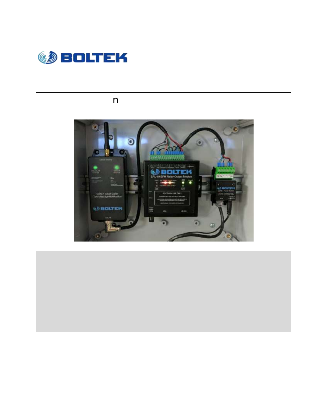
1 GSM Cellular Dialer (with cellular antenna)
1 ERL-10 Programmable Output Relay Module
1 EPM-1 Power Module or EFA-21 Power/Data Module
1 AC wall adapter,
120VAC to 12VDC for North America/Japan
Or 120V/220V AC to 12VDC Universal Power Adapter
1 External cellular antenna
1 Enclosure (Rated IP68)
1 USB Flash Drive with Windows software and Drivers
1 User Manual
Unpack your GSM-1 and check that all parts are included.
Chapter
1
T
Page 6
C H A P T E R 1 - S E T U P
2
Installing SIM Card
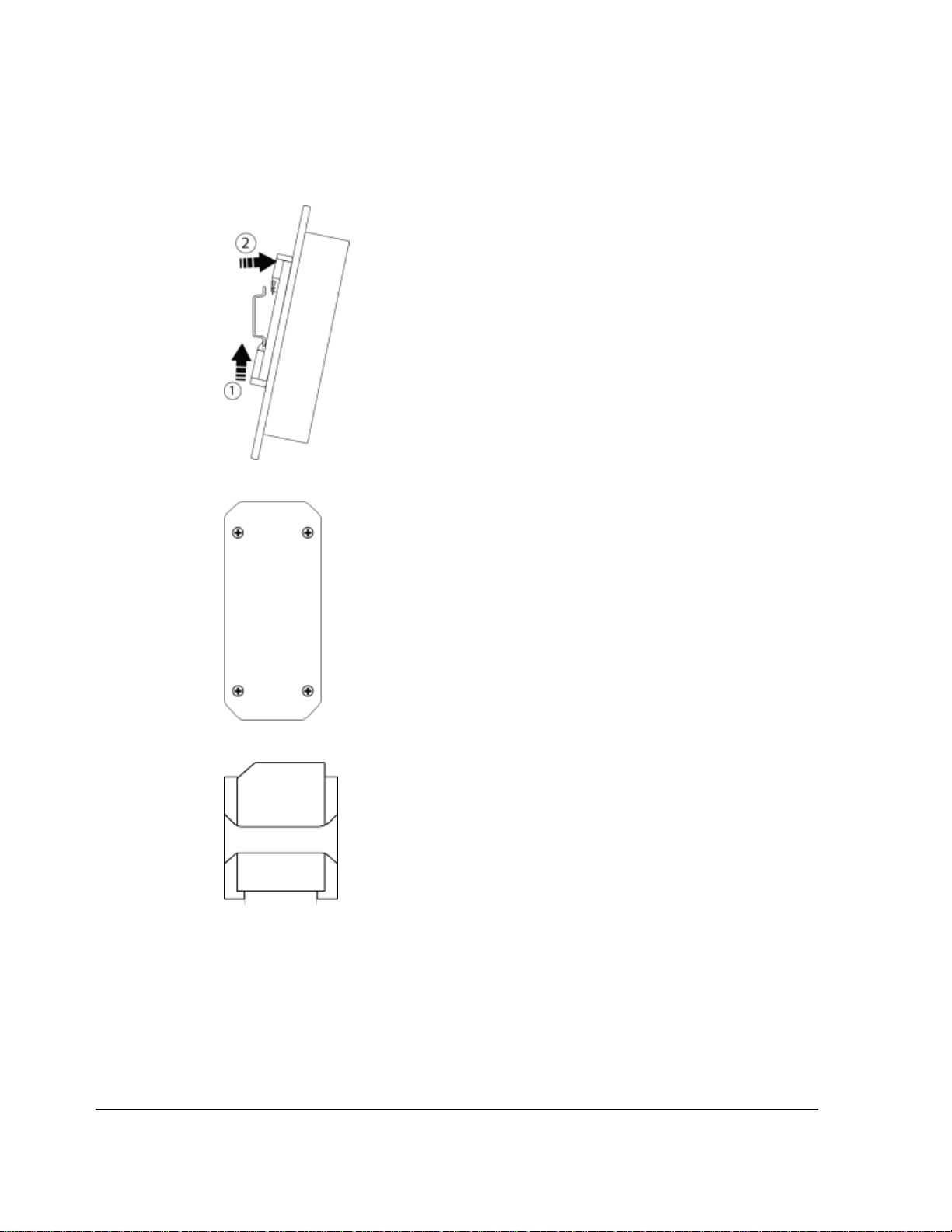
1) Detach GSM-1 from the DIN Rail by pushing up then pull top towards you then
pull off the rail.
2) Remove the four screws on the back of the GSM-1 using No.1 Philips screwdriver
3) Insert SIM card with contacts facing down and angled corner to the top.
4) Reattach GSM-1 case with the four screws and place back on the DIN Rail
Page 7

C H A P T E R 1 - S E T U P
3
Setup Instructions
1) Install EFM-100 (and LD-250 if purchased). Please refer to user manuals of each
detector for installation details.
2) Connect the EFM-100 Cat6 cable to EPM-1/EFA-21 RJ45 connector.
3) Connect (optional) DB9 cable from LD-250 to ERL-10 RS232 connector
4) Connect the USB cable from your computer USB port to the USB connector of
your ERL-10.
5) Plug in the AC power adapter into the lead of the EPM-1/EFA-21 and into an AC
outlet. The EFM-100, ERL-10 and GSM Dialer will all power up. All of the LEDs
on the ERL-10 will illuminate the indicator lights for 2 seconds then the EFM Data
LED will start blinking. If the fault LED stays on, check EFM-100 power and
connection or refer to Fault Code chart listed in Appendix A
6) After the ERL-10 is powered up, the USB drivers should automatically install if
there is an active internet connection on the computer. If there is no internet
connection, the USB driver install program can be found on the Boltek USB Flash
Drive in the ERL-10 folder.
7) Run the ERL-10 program executable on the USB Flash Drive to install the
Configuration, Monitor, and Data Viewer applications.
8) After installation has completed, run the Config application to set alarm parameters
and click “Write config to ERL-10” to save settings to the ERL-10.
Note: The GSM-1 only works with the Yellow and Red alarm, the All Clear, and
the Fault relays.
9) If viewing alarm status on a PC or Laptop, run the Status Monitor software to view
active alarms/all clear status.
Unless changed, once the ERL-10 is powered up, it goes into Survey Mode for a default
time of 20 minutes. If no lightning activity is detected, then the All Clear status light will
illuminate and normal operation of the device will begin.
Page 8

C O N F I G U R A T I O N
4
Dialer Configuration
Adding Numbers
All of the numbers can be stored by sending text message commands to the GSM-1 dialer. The
commands are not case sensitive, so any case can be used when sending commands.
In order to add text numbers, at least one Master number needs to be setup first before adding other
numbers. The command for adding a Master number is
Master<space>number.
Ex: Master 15551234567.
To add a text number to the GSM-1, use the command
Textnum<space>number.
This is
independent from the master number, so it will also need to be added as a separate Text number by
using this command as well to receive the text message alerts.
Ex: Textnum 15551234567.
To remove a number from the dialer, use the command
Remove<space>number.
sent from a
master number that is stored in the dialer.
Ex: Remove 15551234567
To view a list of the numbers stored on the dialer, use the command
List
➢ ‘M’ beside the number will indicate it is a master number
➢ ‘T’ beside the number will indicate it is a text number.
Chapter
2
Page 9
C O N F I G U R A T I O N
5
Alert Messages
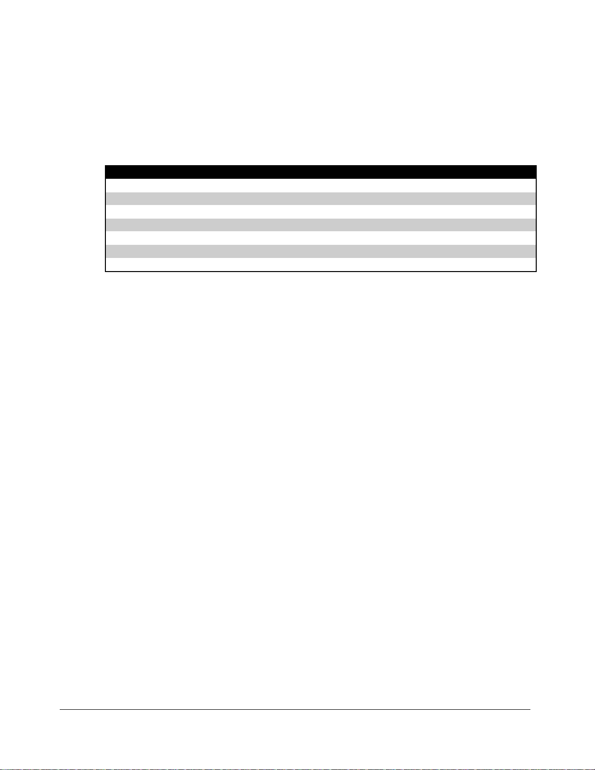
The messages listed in the table below have all ready been pre-programmed into the dialer:
Status
Message
Modify Command
All Clear
ALL CLEAR
CUSTOMCL
Fault Clear
EFM FAULT CLEAR
CUSTOMDL
Fault Active
EFM FAULT
CUSTOMDH
Red Alarm Active
WARN
CUSTOMAL
Red Alarm Clear
WARN CLEAR
CUSTOMAH
Yellow Alarm Active
CAUTION
CUSTOMBL
Yellow Alarm Clear
CAUTION CLEAR
CUSTOMBH
To change the message, send the modify command listed with the corresponding status followed by
the message and a full stop.
To customize an alert message, send the following command:
CUSTOM<A/B/C/D><L/H><space><message>.
Ex: CUSTOMAL RED ALARM IS ACTIVE.
The maximum length of the message is 127 characters and must end with a full stop. Use only text
or number characters in the message, and do not place a full stop in the middle of the message as the
rest of characters after the first full stop will be ignored.
Page 10

Notes
6
Specifications
GSM-1 Specifications
Power Supply Voltage:
11.8-18 VDC, 0.8 Amp
Idle Current:
10-25mA
Current Max:
160mA
SIM Size:
Micro
Antenna:
U.FL
Max Phone Numbers:
512
GSM-1 Dimensions:
5
3/8
" x 2
3/8
" x 1
1/4
" (135 x 60 x 30 mm)
GSM-1 Weight:
0.2 lbs (100 gm)
Enclosure Dimensions:
12
1/2
" x 12" x 6" (318 x 305 x 152 mm)
Enclosure Weight:
(With GSM-1, ERL-10, EPM-1)
5.0 lbs (2.26kg)
Software Specifications
Operating Systems:
Windows 10, 8, 7, Vista (32/64 bit),
2000, XP
Alarm Distance Ranges:
(non Coincidence mode)
0 to 20 mi (0 to 32 km)
Alarm Distance Ranges:
(Coincidence mode):
0 to 40 mi (0 to 64 km)
High Field Alarm Ranges:
0 to 20 kV/m
Appendix
A
Page 11

Notes
7
 Loading...