

Page 1
1
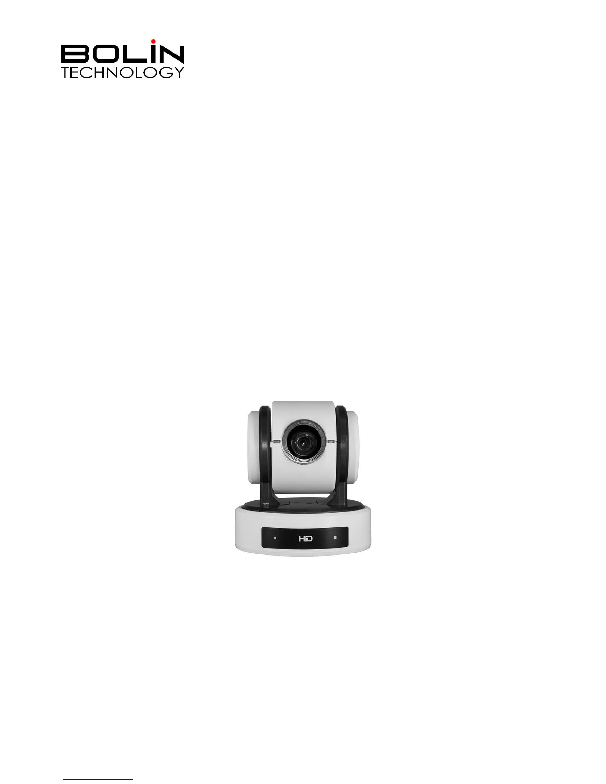
2 Series HD IP Dual Output
PTZ Camera
USER MANUAL
VERSION: VCC-2HDSN-M-10162017
VCC-2HD10S-SN
VCC-2HD10B-SN
© 2017 Bolin Technology
Page 2

2
Contents
IMPORTANT INFORMATION ..................................................................................................................................................... 3
WHAT’S IN THE BOX ................................................................................................................................................................. 5
OVERVIEW ................................................................................................................................................................................ 6
CAMERA VERSION .............................................................................................................................................................................. 6
MODEL NUMBERS ............................................................................................................................................................................. 6
FEATURES ........................................................................................................................................................................................ 6
CAMERA DIAGRAMS ................................................................................................................................................................. 7
CAMERA .......................................................................................................................................................................................... 7
EXTENSION CABLE .............................................................................................................................................................................. 7
REMOTE CONTROLLER ........................................................................................................................................................................ 8
SYSTEM CONFIGURATION ......................................................................................................................................................... 9
CONNECTION .................................................................................................................................................................................... 9
OBTAIN VIDEO SIGNAL ..................................................................................................................................................................... 10
CAMERA CONTROL METHODS AND SYSTEM CONFIGURATIONS ................................................................................................................. 11
SETUP CAMERA ID, BAUD RATE AND CONTROL PROTOCOL ...................................................................................................................... 15
DIP SWITCH SETTINGS ............................................................................................................................................................ 16
ADJUSTING AND SETTING WITH MENUS................................................................................................................................. 18
EXPOSURE MENU ......................................................................................................................................................................... 19
WHITE BALANCE MENU ................................................................................................................................................................ 19
PICTURE MENU............................................................................................................................................................................. 20
PAN TILT ZOOM MENU ................................................................................................................................................................. 20
SYSTEM MENU ............................................................................................................................................................................. 21
OPERATION USING THE INFRARED REMOTE CONTROLLER ..................................................................................................... 22
PAN/TILT AND ZOOM OPERATION ...................................................................................................................................................... 22
OPERATING MULTIPLE CAMERAS WITH THE INFRARED REMOTE CONTROLLER .............................................................................................. 23
ADJUSTING THE CAMERA ................................................................................................................................................................... 23
STORING THE CAMERA SETTINGS IN MEMORY — THE PRESETTING FEATURE ............................................................................................... 24
MENU CONFIGURATION ......................................................................................................................................................... 25
DIMENSION ............................................................................................................................................................................ 26
SPECIFICATIONS ...................................................................................................................................................................... 27
Page 3
3
Operating Instructions
Thank you for purchasing our product. If there are any questions, please contact the authorized dealer.
Before operating the unit, please read this manual thoroughly and retain it for future reference.
Copyright
Copyright 2015-2016 Bolin Technology all rights reserved. No part of this manual may be copied, reproduced,
translated, or distributed in any form or by any means without prior consent in writing from our company.
Trademark Acknowledgement
and other Bolin's trademarks and logos are the property of Bolin Technology. Other trademarks,
company names and product names contained in this manual are the property of their respective owners.
IMPORTANT INFORMATION
Legal Notice
Attention:
To ensure account security, please change the password after your first login. You are recommended to set a strong
password (no less than eight characters).
The contents of this document are subject to change without prior notice. Updates will be added to the new version of this
manual. We will readily improve or update the products or procedures described in the manual.
Best effort has been made to verify the integrity and correctness of the contents in this document, but no statement, information,
or recommendation in this manual shall constitute formal guarantee of any kind, expressed or implied. We shall not be held
responsible for any technical or typographical errors in this manual.
The product appearance shown in this manual is for reference only and may be different from the actual appearance of your
device.
This manual is a guide for multiple product models and so it is not intended for any specific product.
In this manual, the illustrations of displayed interface, parameters displayed, drawings and value ranges may vary with models.
Please see the actual product for details.
Due to uncertainties such as physical environment, discrepancy may exist between the actual values and reference values
provided in this manual.
Use of this document and the subsequent results shall be entirely on the user’s own responsibility.
Safety Information
WARNING!
Installationandremovaloftheunitanditsaccessoriesmustbecarriedout by qualified personnel. You must read all of the
Safety Instructions supplied with your equipment before installation and operation.
Warnings:
If the product does not work properly, please contact your dealer. Never attempt to disassemble the camera yourself.
(We will not assume any responsibility for problems caused by unauthorized repair or maintenance.)
This installation should be made by a qualified service person and should conform to all the local codes.
When shipping, the camera should be packed in its original packaging.
Make sure the power supply voltage is correct before using the camera.
Do not drop the camera or subject it to physical shock.
Do not touch sensor modules with fingers. If cleaning is necessary, use a clean cloth with a bit of ethanol and wipe it
gently. If the camera will not be used for an extended period of time, put on the lens cap to protect the sensor from dirt.
Do not aim the camera lens at the strong light such as sun or incandescent lamp. The strong light can cause fatal
damage to the camera.
Page 4
4
Maintenance Precautions:
If there is dust on the front glass surface, remove the dust gently using an oil-free brush or a rubber dust blowing
ball.
If there is grease or a dust stain on the front glass surface, clean the glass surface gently from the center outward
using anti-static gloves or an oil-free cloth. If the grease or the stain still cannot be removed, use anti-static
gloves or an oil-free cloth dipped with detergent and clean the glass surface gently until it is removed.
Do not use organic solvents, such as benzene or ethanol when cleaning the front glass surface.
Regulatory Compliance
FCC Part15
This equipment has been tested and found to comply with the limits for digital device, pursuant to part 15 of the FCC
Rules. These limits are designed to provide reasonable protection against harmful interference when the equipment is
operated in a commercial environment. This equipment generates, uses, and can radiate radio frequency energy and, if
not installed and used in accordance with the instruction manual, may cause harmful interference to radio
communications. Operation of this equipment in a residential area is likely to cause harmful interference in which case
the user will be required to correct the interference at his own expense.
ThisproductcomplieswithPart15oftheFCCRules.Operationissubject to the following two conditions:
This device may not cause harmful interference.
This device must accept any interference received, including interference that may cause undesired operation.
LVD/EMC Directive
This product complies with the European Low Voltage Directive 2006/95/EC and EMC Directive
2004/108/EC.
WE EE Directive–2002/96/EC
The product this manual refers to is covered by the Waste Electrical & Electronic Equipment (WEEE)
Directive and must be disposed of in a responsible manner.
Page 5
5
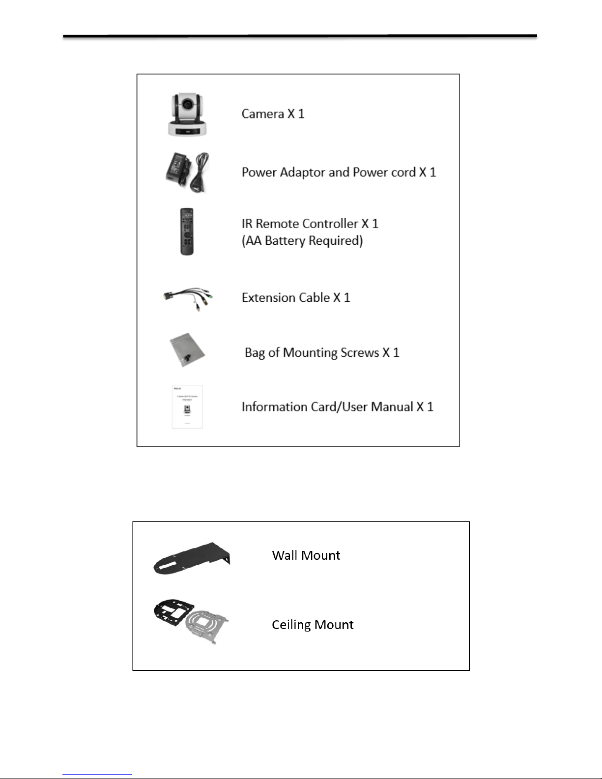
WHAT’S IN THE BOX
Accessories (Optional)
Page 6

6
Overview
Camera Version
Hardware: HV:V.0A.000000eg.02.00A.02.A01
Software: SV:V0A0400A020401A01
Model Numbers
This user guide is suitable for the following models:
VCC-2HD10S-SN
VCC-2HD10B-SN
Features
Resolution: 1080P,720P
Zoom: Optical 10X
Camera Body Video Output: HD-SDI(3G), DVI.
Extension Cable Provides:
o Video Output: IP, CVBS.
o Control: RS-232 port, RS-422/485 port
o Audio Input/output
The camera can simultaneously have SDI video output and IP video output and CVBS video
output.
Power: DC 12V
±350-degree continuous pan, +90 degree and -30 degree continuous tilt
128 presets, Speed up to 200 degrees/sec
Standard mounting and ceiling mounting with E-Flip function
IR remote control, RS-232 control, RS-422/485 control
You can use the infrared remote controller to set the camera and also to select panning, tilting and
zooming from the setting menu.
You can store up to 6 presets of camera direction and camera parameters into the camera. (Up to
6 presets on remote controller or 128 presets via protocol programming.)
Page 7
7
Camera Diagrams
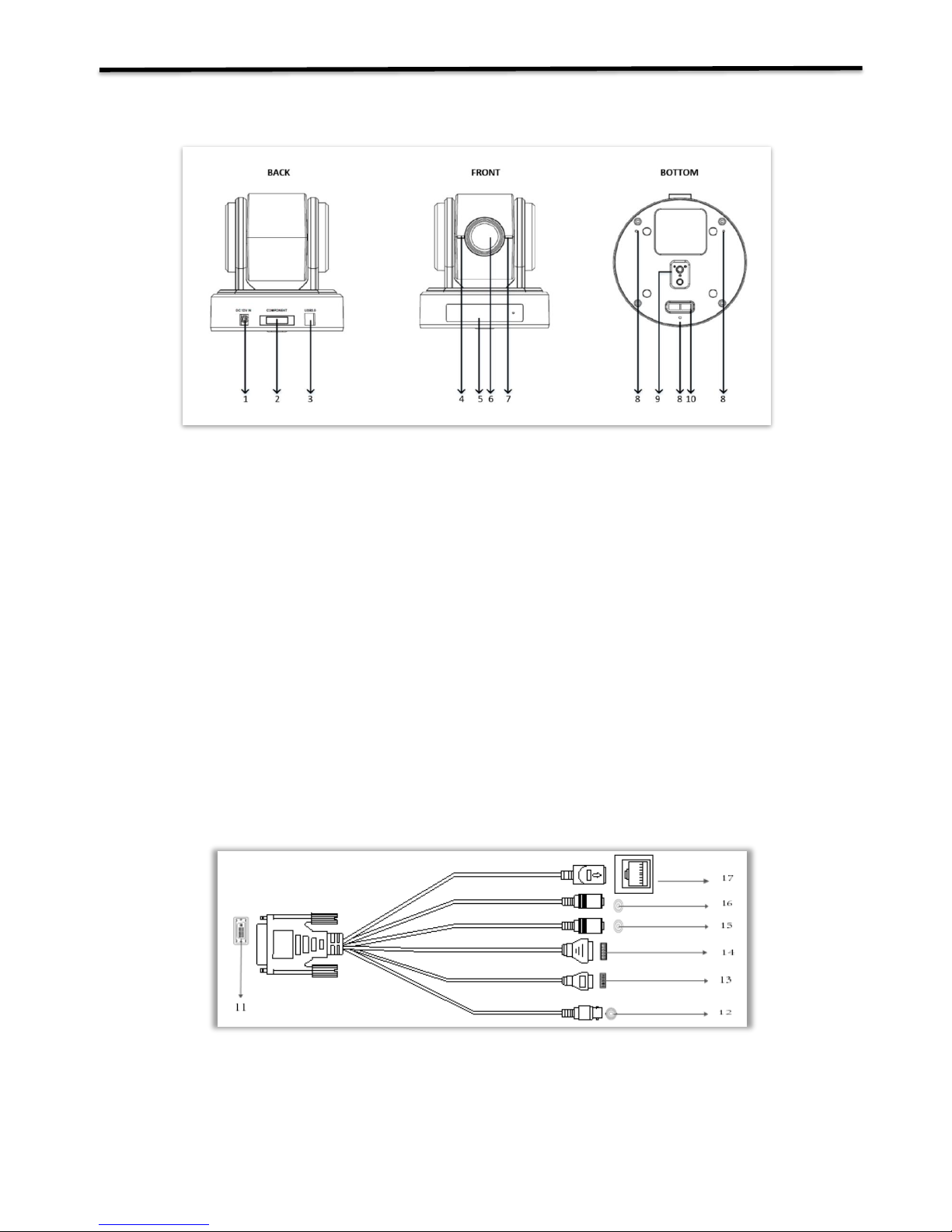
Camera
1. 12V DC Power Port
Connect the supplied AC power adaptor and cord.
2. Component Port for Extension Cable
Extension Cable provides RS-232 port, RS-422/485 port, IP, CVBS video output and audio input/output.
3. SDI Port
3G-SDI
4. Power LED Indicator
Turns green when the camera is connected to power outlet. When the power is turned on, it takes about 15 to 30
seconds to display the image after LED turns on.
5. IR Remote Controller Sensors
These are sensors to receive commands from infrared remote controller.
6. Lens
This is a 10X magnification optical zoom lens.
7. Communication LED Indicator
Flashes orange when the camera receives commands from the infrared remote controller.
8. Fix mounting holes
For original wall/ceiling mount bracket
9. Tripod mounting holes
10. Bottom DIP Switch
Extension Cable
11. Extension Port DVI-I(Connect to the camera body)
12. CVBS Video Output
13. RS232 Control Port
14. RS422/485 Control Port
15. 3.5MM Audio Input
16. 3.5MM Audio Output
17. Ethernet Port
Page 8
8
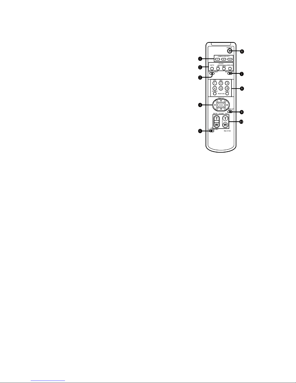
Remote Controller
1. CAMERA SELECT
2. FOCUS
Auto
Far
Near
Manual
3. DATA SCREEN
On screen menu display ON/OFF
4. PAN-TILT
Pan and Tilt direction control
HOME: Home position, Resolution reset
5. L/R DIRECTION SET
Left and right orientation setting
6. POWER
7. BACK LIGHT
8. PRESET/RESET POSITION
9. PAN-TILT RESET
10. ZOOM IN/OUT
Slow T
Slow W
Fast T
Fast W
Page 9
9
System Configuration
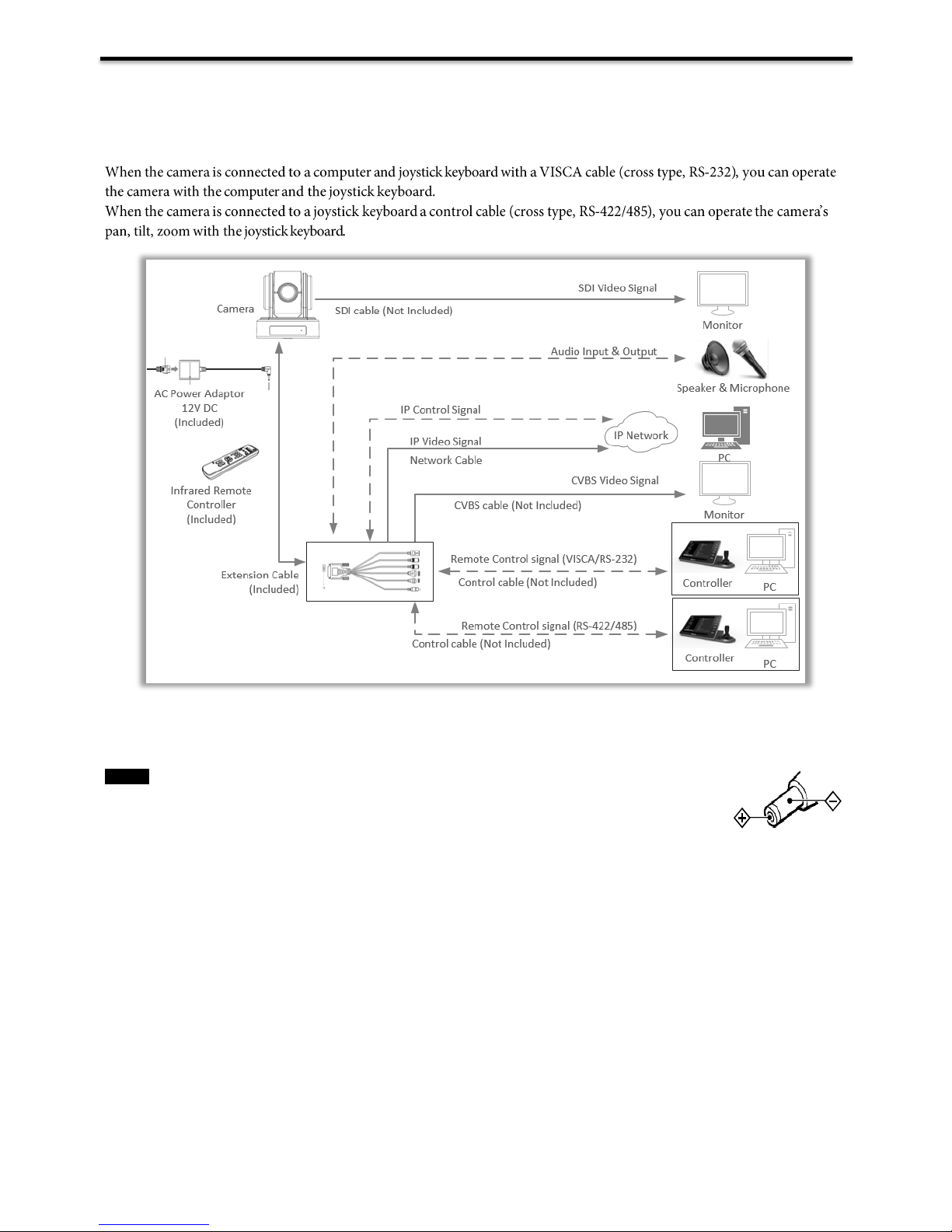
Connection
In this connection configuration, DVI cable, CVBS video cable, data cable is required. To obtain these third party
components or accessories, consult the dealer where you bought your camera.
Notes
Use only the DC power adaptor (JEITA type4) supplied with the unit. Do not use any other
DC power adaptor.
Polarity of the plug
You have to set the video format of the signal to output from the camera. For detailed information on how to set
the video format, see “SYSTEM SELECT switch” on page19.
Page 10

10
Obtain Video Signal
The camera can simultaneously have HD-SDI, IP video output and CVBS.
SDI Video Signal
The camera can simultaneously stream SDI video output with DVI video output.
1. Connect SDI cable in between the camera your SDI Device/display.
2. You now have SDI video output.
CVBS Video Signal
1. Connect CVBS cable in between the camera with Extension Cable plugged in and your CVBS Device/display.
2. You now have CVBS video output.
IP Video Signal
1. For obtaining IP video signal guidance refer to this user manual Part-Two.
Camera Initial setting status Information
Information of the camera initial setting status will display for 5
seconds.
1. Camera physical ID for RS-422/485 control
2. Camera ID for IR Remote Controller
3. IR remote control signal receive current setting
4. Baud Rate current setting
5. Control COMM Port current setting
6. Video format current setting
7. HDMI current setting
8. Model number
9. Firmware version
PELCO ID: 001
IR ID: 01
IR-RECEIVE: ON
BAUD RATE: 9600
COMM TYPE: 232
FORMAT: 1080P30
HDMI OUT: YUV
MODEL TYPE: ------
SV: V0A0100A020401A01
Page 11
11
Camera Control Methods and System Configurations
This unit has multiple ways of controlling the camera and various system configuration capabilities using optional
products. This section describes ways of controlling and typical system examples with the required components and
usage of each system.
1. Use the Infrared Remote Controller
2. Use RS-232 (VISCA), need to use Extension Cable.
3. Use RS-422/485 (PELCO P/D), need to use Extension Cable.
4. Use IP control.
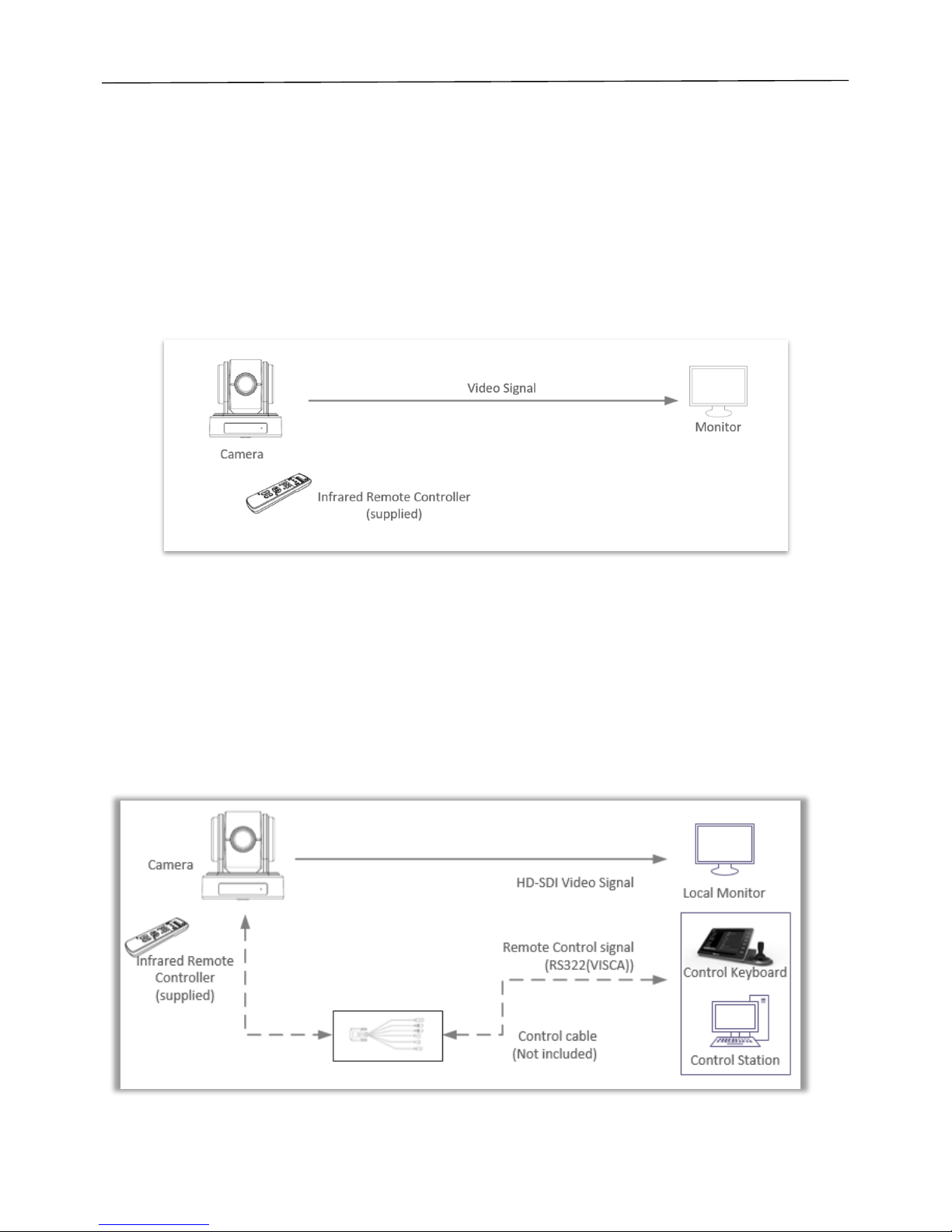
Use the Infrared Remote Controller
To operate the camera from a short distance.
System Configuration A
For IR remote control details, refer to Operation Using the Infrared Remote Controller, see page 21.
Use RS-232 (VISCA)
You can use RS-232 port to connect to optional controllers, such as joystick control keyboard, control PC station, to
operate the camera.
To perform pan/tilt and zoom operations using the joystick of the control keyboard, and to perform the Preset operation
using the control buttons.
An application software that supports this unit is needed if you use PC station.
System Configuration B
Page 12

12
RS232 Connection
1. Set RS232 control method on Bottom Dip Switch. (See page 15).
2. Set Baud Rate on Bottom Dip Switch to the same as Baud Rate setting on the keyboard you are using. (See page 16).
3. Reboot the camera by turning it Off/On after the Bottom Dip Switch has been set up correctly.
4. Does not need setting camera address in way of RS232 controlling.
5. The controller must be VISCA compatible.
6. Camera does not support Daisy Chain in RS232 control mode.
7. You can make RS232 connection cable if you have the following applications:
Use RS-422(VISCA)/RS485 (PELCO P/D)
You can use RS-422/485 port connect to optional controllers, such as joystick control keyboard, control PC station, to
operate the camera.
To perform pan/tilt and zoom operations using the joystick of the control keyboard, and to perform the Preset operation
using the control buttons.
An application software that supports this unit is needed if you use PC station.
System Configuration C
Page 13
13
RS422/482 Connection
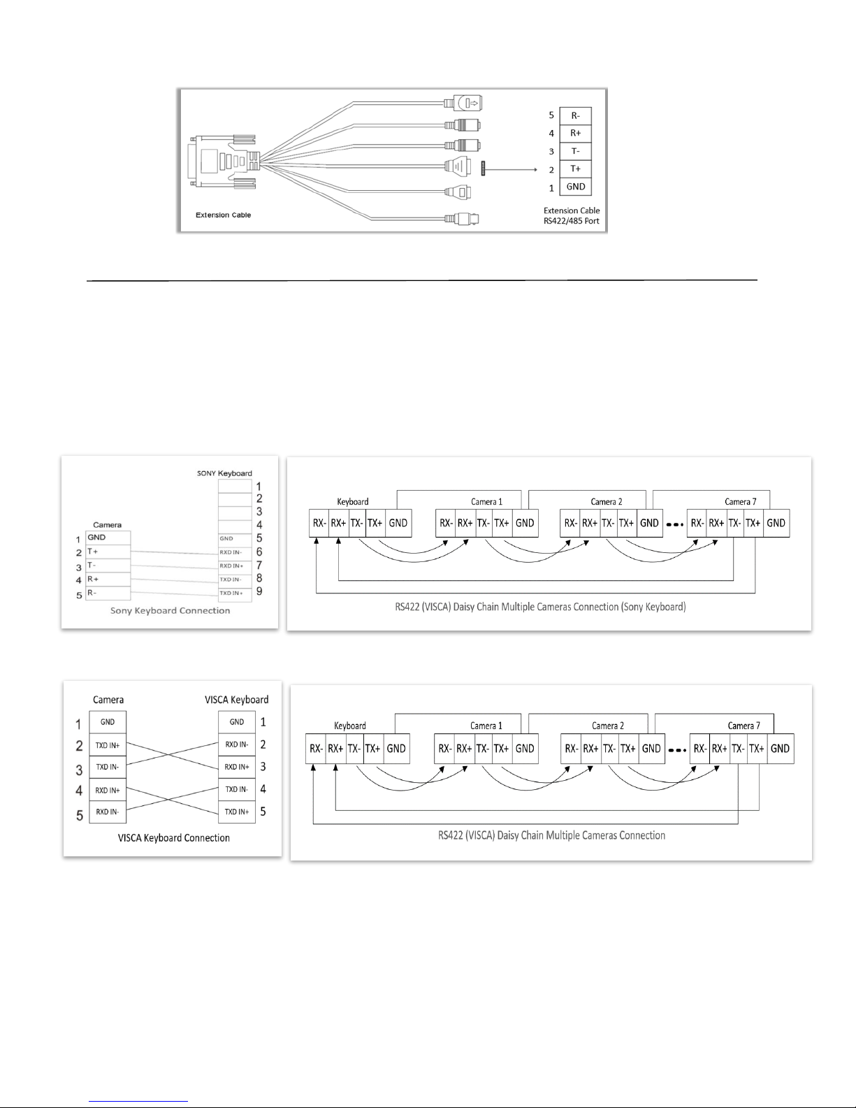
RS422 (VISCA) connection
1. Set RS422 control method on Bottom Dip Switch (See page 15).
2. Set Baud Rate on Bottom Dip Switch to the same as Baud Rate setting on the keyboard you are using. (See page 16).
3. Reboot the camera by turning it Off/On after the Bottom Dip Switch has been set up correctly.
4. Does not need setting camera address in way of RS422 (VISCA) controlling.
5. The controller must be VISCA compatible.
6. Camera supports Daisy Chain connection up to 7 cameras.
7. The connection of SONY keyboard is different than other VISCA (None-Sony) keyboard.
SONY Keyboard RS422 Connection
VISCA (None-Sony) Keyboard RS422 Connection
Page 14
14
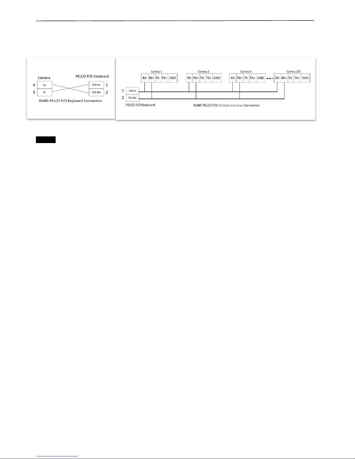
PELCO P/D Keyboard RS485 Connection
1. Use PELCO P/D compatible keyboard.
2. Use preset 95# on the keyboard to bring up/exit camera OSD menu.
3. Use joystick and Button “OPEN” or “CLOSE” to navigate OSD menu.
4. To operate keyboard, please refer to the user manual of the keyboard you are using.
Note
For RS-232 VISCA control, this unit does not support daisy chain connection for using multiple cameras.
For control details, refer to Operating Instructions of control keyboard/station software.
Youneedtomatchthecommunicationspeedbetweenthecameraandthejoystick controller.
YoucannotusetheRS-232connectionswhenusingtheRS422/485connection.
Use IP control
1. For IP control guidance refer to this user manual Part-Two.
Operating Multiple Cameras Using RS-422/485
Using RS-422 (VISCA), you can connect up to 7 cameras.
Using RS-485 (PELCO), you can connect up to 255 cameras.
Using RS-485 (PELCO), all camera addresses must be set up before the connection. You can set the camera
address by operating OSD menu, or by setting the Dip Switch on the bottom of the camera.
In this case, you can use multiple control keyboards.
The joystick of the remote keyboard controller allows comfortable pan/tilt and zoom operations.
Page 15
15
Setup Camera ID, Baud Rate and Control Protocol
In order for you to control a camera, the camera ID, baud rate and control protocol have to be set up in advance, Baud
rate and the camera ID setting on the camera have to be the same as baud rate and camera ID setting on the
system/control keyboard. The camera can auto detect the VISCA and PELCO-D, only need to set up the camera address
and baud rate.
Connect the camera to a monitor. There is an initial setting page displaying on the screen for 5 seconds when the camera
is powered on. On the page, it shows the factory default setting of the camera ID, baud rate and other information.
Suggest taking a picture of this default setting information for setting keyboard use. Set the keyboard or control system to
match the camera ID, baud rate setting with the camera.
1. Camera supports VISCA and PELCO-D protocols, protocol is detected automatically by the camera.
2. Factory Default Setting: For both SDI and IP video, Baud Rate: 9600, Camera ID: 001, Pelco Protocol.
3. Use RS485 Pelco-D can control up to 255 cameras, camera ID from 001 to 255 has to be set.
4. Use RS422 VISCA protocol can control up to 7 cameras, camera ID from 1 to 7 has to be set.
5. Supports baud rate of 2400bps, 4800bps, 9600bps and 38400bps.
6. How to set up the address and baud rate of the camera for SDI, please see the Page21.
7. On the keyboard side, for RS485 control, go into the camera setting menu, select the camera address/ID you
want to set up for, set the baud rate to match the same as the one has been set on camera side, select protocol
Pelco D for RS485 control. (How to set up the menu of the keyboard, please refer to the instruction of the
keyboard you are using.)
8. On the keyboard side, for VISCA control, select RS232/RS422 control
method, set the baud rate to match the same as the one has been set on camera
side. (How to set up the VISCA keyboard, please refer to the instruction of the
keyboard you are using.)
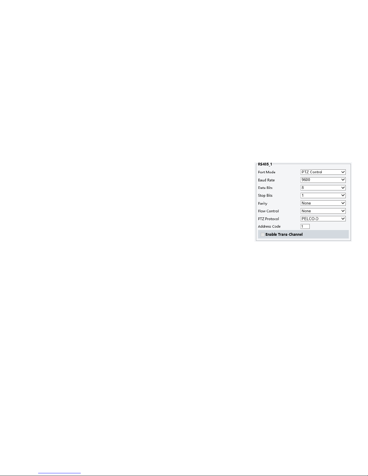
9. On IP control side, go into the camera IP web interface setting page by using
browser to login camera IP address (Default set to 192.168.0.13), go to “Setup-
System-Port&Devices” setting page, set the Baud Rate, camera ID, Protocol to
the same as the ones that have been set on the camera side. (For detail, please
refer to Part Two: Network Camera User Manual Page 25.)
10. SDI and IP video setting have to be matching with each other, if you change
Page 16
16
DIP SWITCH SETTINGS
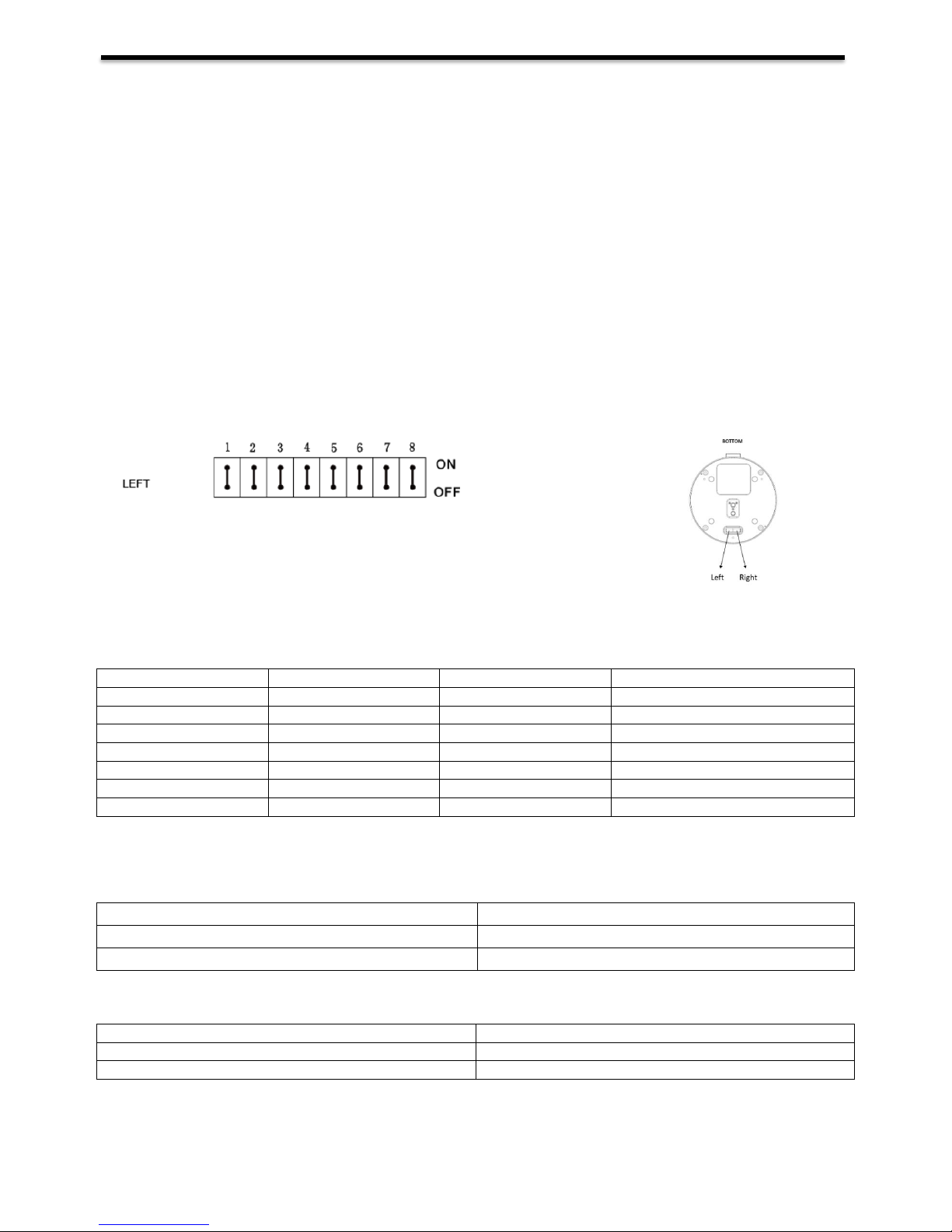
The bottom dip switch is for setting the camera configuration for following items:
1. Camera ID Address for RS-485 PELCO protocol
2. Video output / Video color space
3. RS-232 / RS-422/485 selection
4. RS-232 / RS-422/485 baud rate
5. Video resolutions selection
6. IR remote controller ID
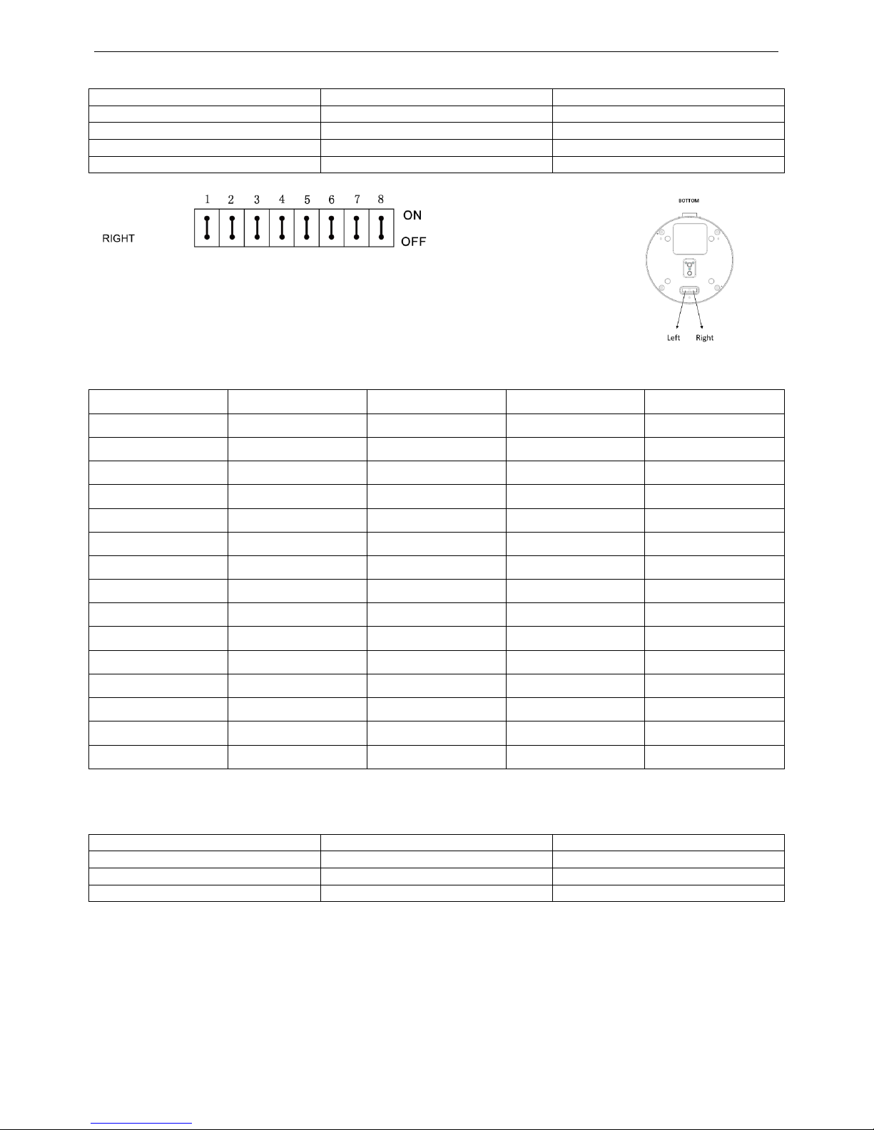
Setting of the BOTTOMDIP Switches
Turn off power to the camera before changing the DIP switch settings.
Power on the camera to have the new Dip Switch setting activated.
From the above list, No.1 Camera ID address and NO.2 Video resolution settings can be set in camera OSD menu as
well. The camera takes either the way of OSD menu setting or the way of bottom DIP switch setting. They override each
other. After the camera is turned on, the camera takes the last setting before it is turned on, either set through the OSD or
bottom DIP switch.
The Bottom DIP Switch Settings
SWI: Factory Default Setting: ON, OFF, OFF, OFF, OFF, OFF, OFF, ON.
Bit1~3: Camera Address setting for VISCA protocol
Bit4: Video Output/Video Color Space
Bit5: Reserve
Bit6: RS-232/RS-422
Bit7~8: RS-232/RS-422 Baud Rate
1. Camera Address setting for VISCA protocol
B1
B2
B3
Address
ON
OFF
OFF
1 (Default)
OFF
ON
OFF 2 ON
ON
OFF
3
OFF
OFF
ON 4 ON
OFF
ON
5
OFF
ON
ON 6 ON
ON
ON
7
2. Video Output/Video Color Space
When using HDMI output to display on HDMI device, set the Dip switch B4 to OFF.
When using HDMI to DVI convertor to have DVI video output, set the Dip switch B4 to ON.
3. RS-232 / RS-422 Setting
B6
RS-232 / RS-422
OFF
RS-232
ON
RS-422
B4
Color Space Setting
OFF
YUV
ON
RGB
Page 17
17
4. RS-232 / RS-422 Baud Rate Setting
B7
B8
RS-232 / RS-422 Baud Rate Setting
OFF
OFF
2400 bps
ON
OFF
4800 bps
OFF
ON
9600 bps (Default)
ON
ON
38400 bps
SW2: Factory Default Setting: OFF, OFF, OFF, ON, OFF, OFF, OFF, OFF
Bit 1~4: Video resolution setting
Bit5~6: Reserve
Bit7~8: IR remote controller ID setting
1. Video Resolution Setting
B1
B2
B3
B4
Video Resolution
OFF
OFF
OFF
OFF
1080i59.94
OFF
OFF
OFF
ON
1080p29.97
OFF
OFF
ON
OFF
720p59.94
OFF
OFF
ON
ON
1080p59.94
OFF
ON
OFF
OFF
Empty
OFF
ON
OFF
ON
1080i60
OFF
ON
ON
OFF
1080p30
OFF
ON
ON
ON
1080p60
ON
OFF
OFF
OFF
1080i50
ON
OFF
OFF
ON
1080p25
ON
OFF
ON
OFF
720p50
ON
OFF
ON
ON
1080p50
ON
ON
OFF
OFF
Empty
ON
ON
OFF
ON
Empty
ON
ON
ON
ON
720p60
2. IR Remote Controller ID Setting
B7
B8
IR Remote Controller ID
OFF
OFF 1 ON
OFF
2
OFF
ON
3
Page 18
18
Adjusting and Setting with Menus
About On-Screen Menus
You can change various settings, such as shooting conditions and system setup of the camera, while observing menus
displayed on a connected computer screen.
This section explains how to read the on-screen menus before starting menu operations.
The menu parameters may vary according to the different product model numbers.
For a complete configurations menu, see “Menu Configuration” (page24).
Note
You cannot perform pan/tilt operations while the menu is displayed.
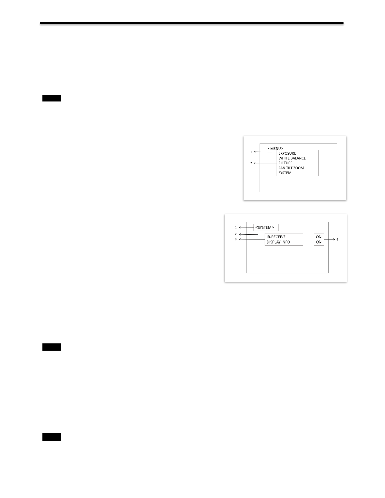
Main Menu
To display the main menu, press the DATA SCREEN button on the supplied infrared remote controller.
1.
Selected Items
Selects a setting menu.
The selected item is shown by the cursor. The cursor moves up or down by
pressing the“↑, ↓” button on the infrared remote controller.
2.
Menu Items
To display a setting menu, select one using the “↑, ↓” button on the infrared
remote controller and press the HOME button on the infrared remote
controller.
Setting Menus
The setting menu selected on the main menu is displayed.
1.
Setting Menu
The name of the setting menu currently selected is displayed here.
2.
Selected Item
Selects a setting item.
The selected item is shown by the cursor.
Move the cursor up or down by pressing the “↑, ↓” button on the
infrared remote controller.
3.
Setting Items
The setting items for this setting menu are displayed. Select the setting item using the “↑, ↓” button on the infrared remote
controller.
4.
Set Value
The currently set values are displayed.
To change a set value, use the “←, →” button on the infrared remote controller.
In some product models, only use “←” button on the infrared remote controller to change the value. To confirm the value,
you can use either “→” button or HOME button.
Control Button
You can select the item by pressing “↑, ↓, ←, →” and HOME button.
1.
You can select a menu item by
“↑, ↓”
button on the infrared remote
controller
. The selected item is shown by
the cursor (Color change).
You can change the value of the item by pressing “←, →” button.
2.
You can move to the next layer by
pressing the HOME button.
3.
You can return to the normal display by
pressing the DATA SCREEN button.
When you are operating the menu using the infrared remote controller, you cannot set IR- RECEIVE in the SYSTEM
menu to OFF. To set IR- RECEIVE to OFF, use the appropriate VISCA command.
Note
Note
Page 19
19
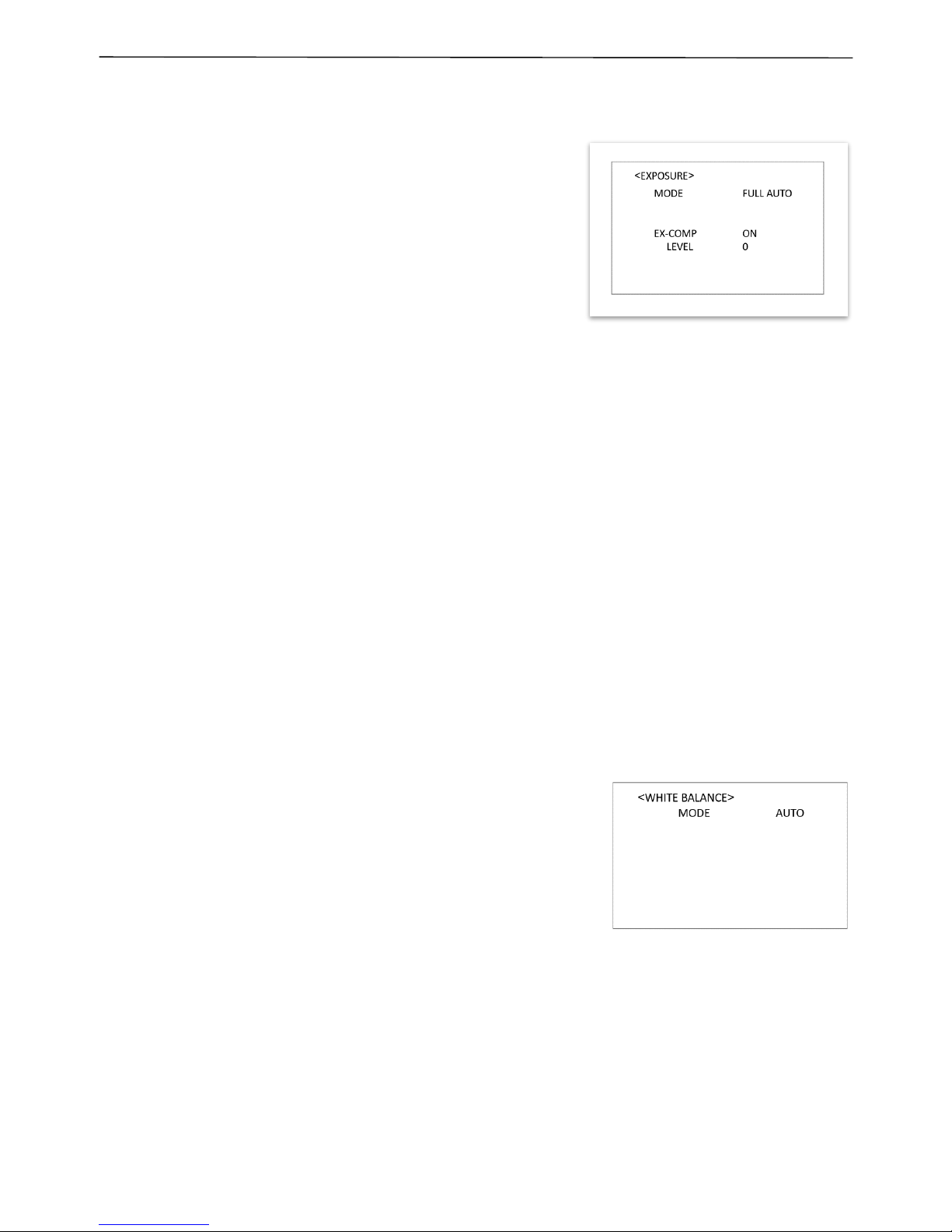
EXPOSURE Menu
The EXPOSURE menu is used to set the items related to exposure.
MODE (Exposure Mode)
FULL AUTO: The exposure is adjusted automatically using the
sensitivity, electronic shutter speed, and iris.
BRIGHT: Adjust the brightness level (LEVEL) manually.
SHUTTER PRI: Shutter Priority mode. The exposure is adjusted
automatically using the sensitivity and iris. Adjust the electronic
shutter speed (SPEED) manually.
IRIS PRI: Iris Priority mode. The exposure is adjusted
automatically using the sensitivity and electronic shutter speed.
Adjust the iris (IRIS) manually.
MANUAL: Adjust the sensitivity (GAIN), electronic shutter speed
(SPEED) and iris (IRIS) manually.
When you select one from various exposure modes, some of the following setting items that are required for the selected
mode appear.
GAIN: Select the gain from the following:
-3, 0, 2, 4, 6, 8, 10, 12, 14, 16, 18, 20, 22, 24,26, 28 dB
SPEED: Select the electronic shutter speed from the following:
1/1, 1/2, 1/4, 1/8, 1/15, 1/30,1/60, 1/90, 1/100, 1/125, 1/180, 1/250,1/350, 1/500, 1/725, 1/1000, 1/1500,1/2000,
1/3000, 1/4000, 1/6000,1/10000 sec.
IRIS: Select the iris the following: CLOSE, F14, F11, F9.6, F8.0, F6.8, F5.6, F4.8, F4.0, F3.4, F2.8, F2.4, F2.0,
F1.6
LEVEL: Select the brightness level from 0, 5 to 31.
EX-COMP (Exposure Compensation)
When MODE is set to one of FULL AUTO, SHUTTER PRI or IRIS PRI, set this item to ON to enable
exposure compensation. When you set EX-COMP to ON, LEVEL appear and you can select the
exposure compensation level from the following:
–10.5, –9, –7.5, –6, –4.5, –3, –1.5, 0, +1.5, +3, +4.5, +6, +7.5, +9,+10.5
If you set the level to 0, exposure compensation will be disabled. Level +10.5 is the brightest and –10.5
is the darkest compensation value.
When EX-COMP is set to OFF, exposure compensation does not function.
WHITE BALANCE Menu
The WHITE BALANCE menu is used to select the white balance mode.
MODE (white balance mode)
Select the white balance mode from the following: AUTO, IN DOOR, OUT
DOOR, OPW (One Push White Balance), ATW (Auto Tracing White
Balance), USER.
When you select USER, R.GAIN (red gain) and B. GAIN (blue gain) appear.
You can select each item in the range from 0 to 255.
When you select the OPW (One Push White Balance)
Perform the following operations:
1. Place an image of white subject (For example: A piece of white paper) in the center of the screen.
2. Press the HOME button of the infrared remote controller.
The one-push white balance adjustment is activated.
Page 20
20
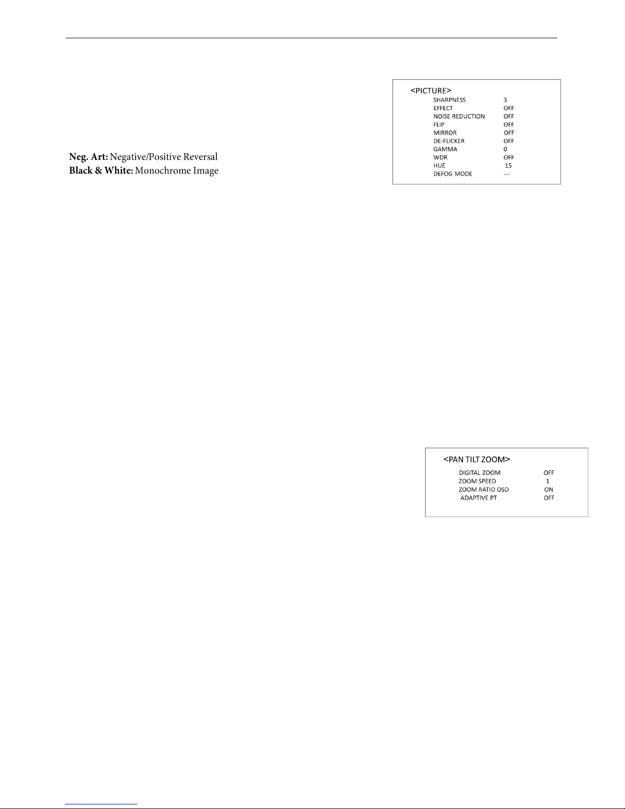
PICTURE Menu
The PICTURE menu is used to set the items related to the picture.
SHARPNESS:
Picture sharpness value ranges from 0 to 20. You can enjoy emphasized edge
and high-resolution images.
EFFECT: (Picture Effect)
It consists of the following functions:
Image effect from Off, B&W, NEG.ART
NOISE REDUCTION:
Noise reduction - you can enjoy clearer images by removing unnecessary noise. You can select 4 levels from OFF (MIN),
1 to 3 (MAX).
FLIP:
Image E-Flipper – Used when ceiling mounting or upright mounting. Set to OFF is upright mode, set to ON is for ceiling
mount.
MIRROR: You can use it to horizontally flip video.
DE-FLICKER:
You can turn it ON if the Video output format frame rate is difference from your country’s electricity Frequency.
GAMMA:
In this mode, the gamma can be set to value from 0 to 4.
WDR: (Wide dynamic range mode): WDR feature is available on certain product models.
Wide Dynamic: ON, OFF. The camera distinguishes light and dark areas within the same scene, adjusts the
brightness for dark areas, and also controls the blown out highlights.
You can select the wide dynamic range mode between ON and OFF
HUE:
You can adjust color phase from 1-15.
Defog mode
When the surrounding area of the subject is foggy and low contrast, the defog mode will make the subject appear
clearer.
PAN TILT ZOOM Menu
The PAN TILT ZOOM menu is used to select the pan/tilt/ zoom mode.
DIGITAL ZOOM:
Set to DIGITAL ZOOM ON, 12X digital zoom is activated.
You can set digital zoom to ON or OFF. When set to OFF, digital zoom does not operate, and only optical zoom is
available. When set to ON, digital zoom takes over after optical zoom reaches MAX (20X/30X). Up to 200X/300X can
be zoom digitally.
When digital zoom is available, the resolution decreases
P/T SPEED:
Set P/T Speed value to from 0 to 5 (The speed from low to high), to change the speed of P/T on remote controller.
ZOOM RATIO OSD (Zoom times display):
Set Ratio OSD to ON, the number of the zoom times that you are operating displays on screen.
Page 21
21
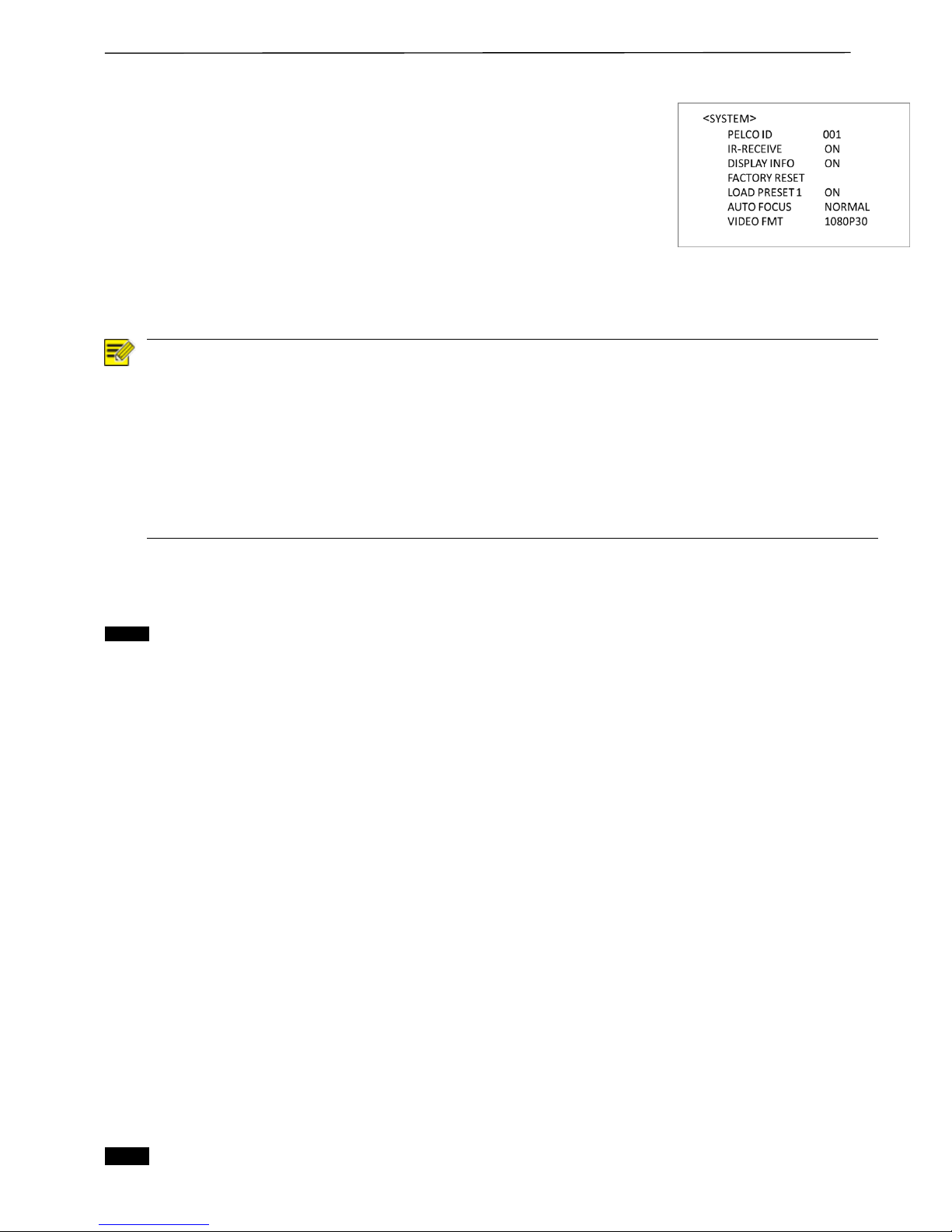
SYSTEM Menu
PELCO ID
This Camera ID setting on the menu is only for Pelco camera ID when using RS485 Pelco
protocol.
Set Camera ID to the address that you want to control to. This value is from 001-255.
For VISCA CAMERA ID:
Set the VISCA camera ID on DIP Switch (See page 16).
Use RS422 VISCA protocol can control up to 7 cameras, camera ID from 1 to 7
has to be set.
After the camera ID and Baud rate is set, to activate the new set camera ID and Baud rate, the camera has to be
rebooted by powering the camera OFF and ON.
NOTE!
After the camera ID and Baud rate is set, to activate the new set camera ID and Baud rate, the camera has
to be rebooted by powering the camera OFF and ON.
For Dual-Output camera, the camera ID and Baud rate on IP web interface has to be set to the same ID as
the camera’s for IP control. (See user manual Part Two)
You may need to reboot the keyboard after you change the camera ID and Baud rate.
Once modified and saved the camera ID and baud rate, please modify the corresponding parameters on
both the keyboard and IP web interface setting, otherwise the camera and keyboard and IP control will be
unable to communicate.
IR-RECEIVE (Infrared Signal Reception)
When this is set to OFF, the camera does not receive the signal from the infrared remote controller.
Be sure to keep it set to ON when you use the infrared remote controller.
Note
You cannot set IR-RECEIVE to OFF when you operate the menu using the infrared remote controller. To set it to OFF,
use the appropriate VISCA controller.
DISPLAYINFO
When this item is set to ON, the message of the camera configuration
appearsforabout3secondsonthescreen, after the camera is powered on or rebooted.
FACTORY RESET
You can select this item to set camera back to Factory Default setting by pressing HOME button to confirm the action.
All data of the camera that have been set will be deleted.
RELOAD PRESET 1:
When this item is set to ON, preset 1 is set to Home position. The camera goes to Home position when it is powered on
or reset.
AUTO FOCUS
Set speed of auto-focusing from Low to Normal.
VIDEO FORMAT:
You can change the video format by adjusting this item. Select the item, press “←” button to choose the video format you
want to set to, then press “→” (Pressing “→” button changes value on some product models) or HOME button to confirm
it. After you confirm your choice, press HOME button again to restore it. The camera will reboot by itself. The new video
format is activated.
You can cancel it by pressing the DATA SCREEN button.
Depending on the video client software you are using, some video software may need to be restarted to obtain the new
video format.
The video formats that you can select from are: 1080I60, 720P30, 720P60, 1080P60, 1080I59.94, 1080P29.97,
720P59.94, 1080P59.94, 1080I50, 1080P25, 720P50, 1080P50
The default video format is set to 1080P60.
Note
The camera video format can be changed by setting bottom DIP switch as well. For detail, see page 17.
Page 22
22
Operation Using the Infrared Remote Controller
Pan/Tilt and Zoom Operation
Panning and Tilting
1. Press the POWER switch.
The camera will turn on and perform the pan/tilt reset operation automatically.
2. Press the arrow button to pan or tilt the camera.
While checking the picture on the screen, press the desired arrow button.
To move the camera in short increments, press the button just for a moment.
To move the camera in long increments, press and hold the button.
To move the camera diagonally, press the “←, →” button while holding down the “↑, ↓”
button.
Restore to starting position
Press the HOME button.
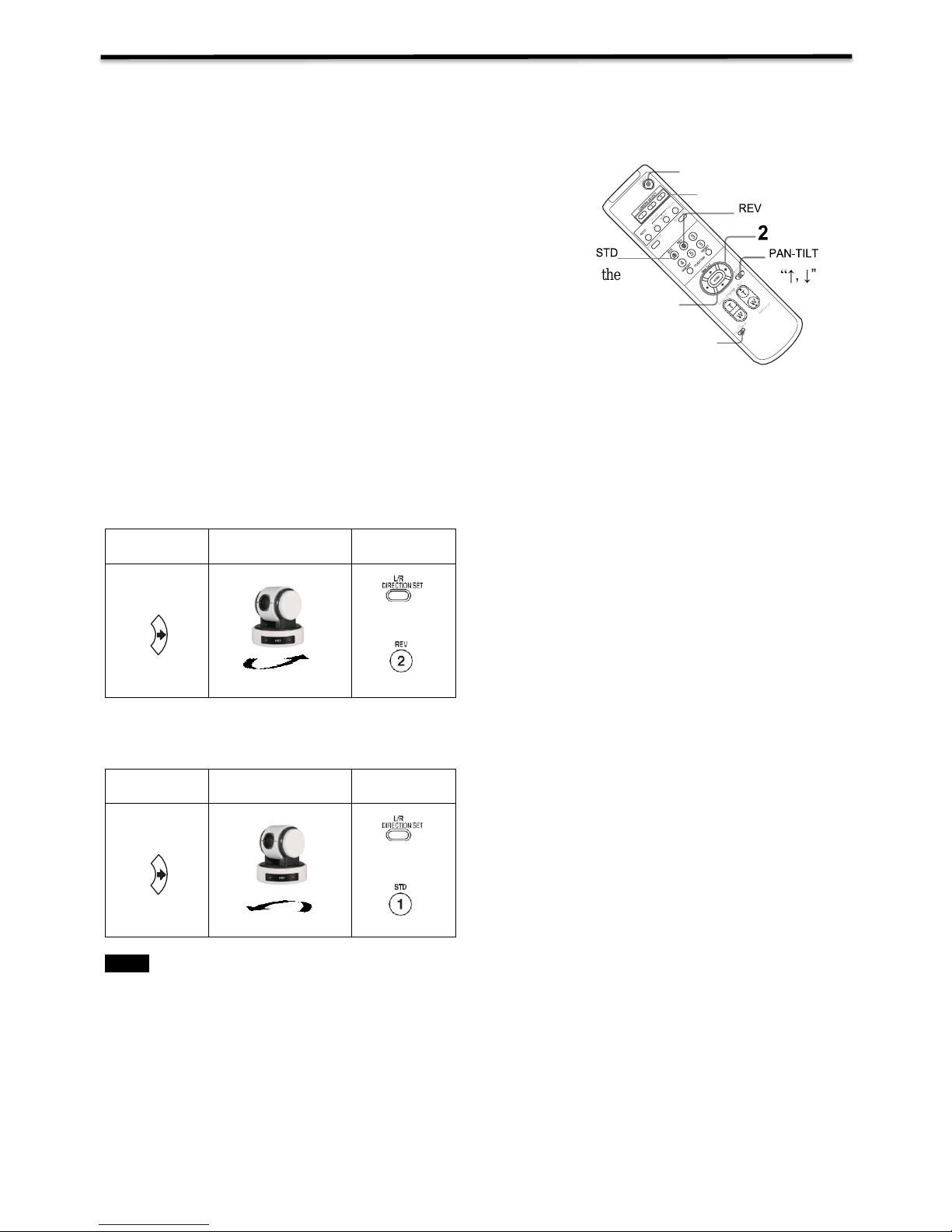
If the camera moves in a different direction from the one that you intended
The camera is preset so that the image output from the camera is rotated toward the right when everyone
press the “←, →” button.
To face the camera toward the opposite direction
You might wish to face the camera toward the opposite direction from that of the button you pressed, for example, when
you change the direction of the camera while checking the picture on the screen. In such a case, press the 2 (REV) button
while holding down the L/R DIRECTION SET button.
Arrow button
Movement of
the camera
Setting
While holding
down
Press
To reset the setting
To reset the setting, press the 1 (STD) button while holding down the L/R DIRECTION SET button.
Arrow button
Movement of
the camera
Setting
While holding
down
Press
Note
The above setting only changes the signal emitted from the infrared remote controller, and does not change the setting of
the camera itself. Therefore, repeat the setting for each infrared remote controller if you are using more than one infrared
remote controller.
When the STANDBY lamp is blinking
If the camera is moved forcibly, or a finger or other object interferes with camera movement, the camera may fail to
memorize the pan/tilt position.
Press the PAN-TILT RESET button to reset the pan/tilt position.
1
CAMERASELECT
RESET
HOME
L/RDIRECTION
SET
Page 23
23
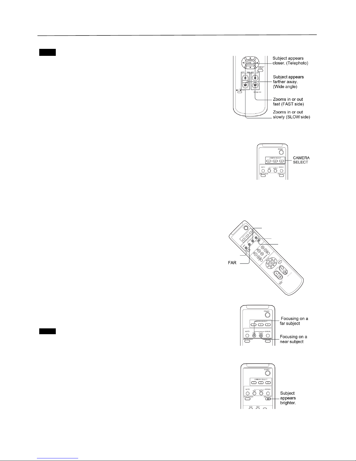
Zooming
Press either of the ZOOM buttons.
Note
When you perform pan/tilt operation while the camera is in the telephoto mode,
the moving speed of the image on the screen may be a little jerky.
Operating Multiple Cameras with the Infrared Remote Controller
1. Set the DIP Switch on the bottom of the camera to the number of camera you
want to operate to 1, 2 or 3.
(See bottom DIP Switch setting instruction)
2. Press the CAMERA SELECT button on the infrared remote controller that
corresponds to the number set in step1.
Then, you can operate the camera(s) specified by number. Every time you operate the camera(s) using the infrared remote
controller, the CAMERA SELECT button pressed in step 2 lights.
Adjusting the Camera
Focusing on a Subject
Focusing the camera on a subject automatically
Press the AUTO button.
The camera focuses on the subject at the center of the screen automatically.
Focusing the camera on a subject manually
After pressing the MANUAL button, press either the FAR or the NEAR button to have the
camera focus on the subject.
Shooting with Backlighting
When you shoot a subject with a light source behind it, the subject becomes dark.
In such a case, press the BACK LIGHT button.
To cancel the function, press the BACK LIGHT button again.
Note
The BACK LIGHT function is effective if MODE is set to FULL AUTO in the
EXPOSURE menu of the camera.
NEAR
MANUAL
BACKLIGHT
AUTO
Page 24
24
Storing the Camera Settings in Memory — the Presetting Feature
Memory (Preset)
Using the preset function, 6 sets of camera shooting conditions can be stored and recalled. 6 sets of camera shooting
conditions can be stored and recalled by using remote controller. Up to 128 presets via protocol programming.
This function allows you to achieve the desired status instantly, even without adjusting the following items each time.
Pan/Tilt Position
Zoom Position
Digital Zoom On/Off
Focus Auto/Manual
Focus Position
AE Mode
Shutter control parameters
Bright Control
Iris control parameters
Gain control parameters
Exposure Compensation On/Off
Exposure Level
Backlight Compensation On/Off
White Balance Mode
R/B Gain
Aperture Control
WD Parameter
The settings stored using this function are recalled when the power is turned on.
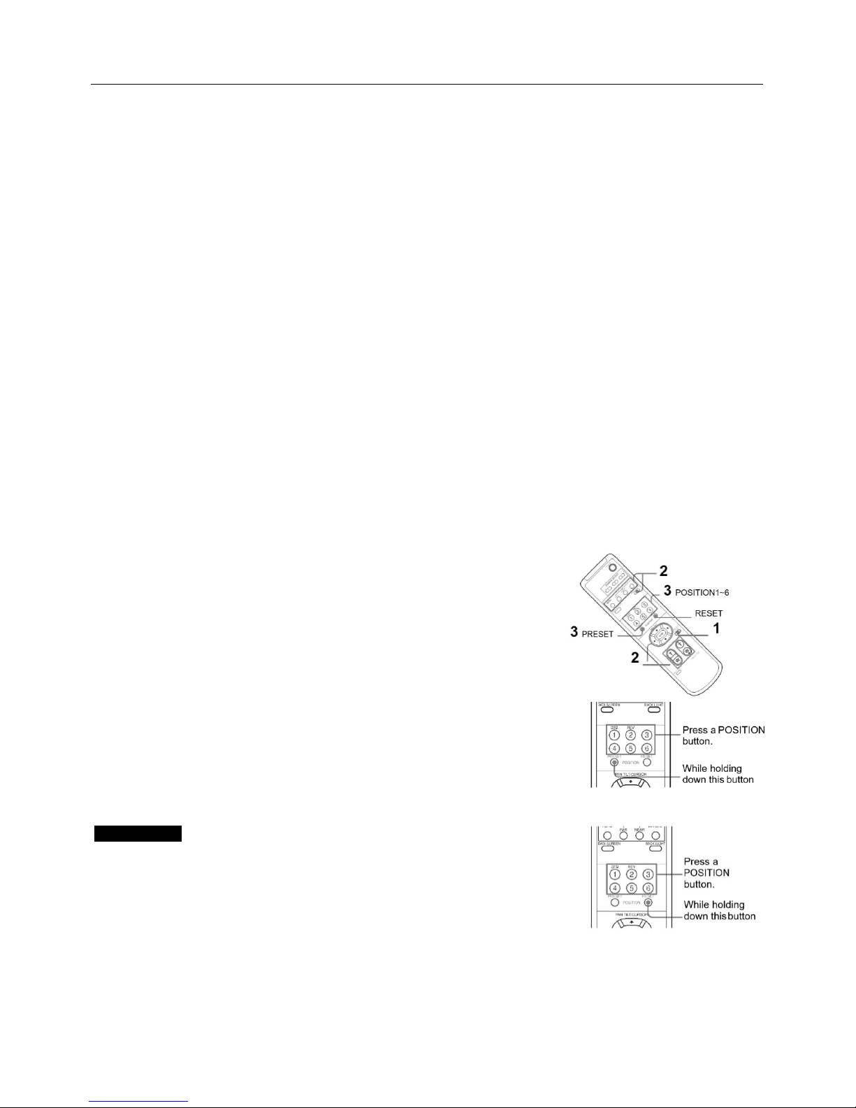
1. Press the PAN-TILT RESET button to reset the pan/ tilt
position.
2. Adjust the position, zooming, focusing and backlighting of the
camera.
While holding down the PRESET button, press any of the POSITION buttons,
1 to 6, in which you want to store the settings.
Recalling the stored settings
Press any of the POSITION buttons, 1to6, in which you have stored the
settings.
Cancelling the preset memory
While holding down the RESET button, press the POSITION button from
which you want to cancel the settings.
Notes
When the power is turned on, the camera starts with the settings
stored in POSITION1.
If you want to retain the previous pan and tilt positions, etc. before the
power is turned off and turned on again, store those positions in
POSITION1.
When you are storing or cancelling the settings in one POSITION,
you cannot call up, store or cancel the settings in another POSITION.
When the menu is displayed on the screen, you cannot perform the operation for storing, recalling, or
cancelling the setting. Be sure to return to the normal display before starting these operations.
Page 25
25
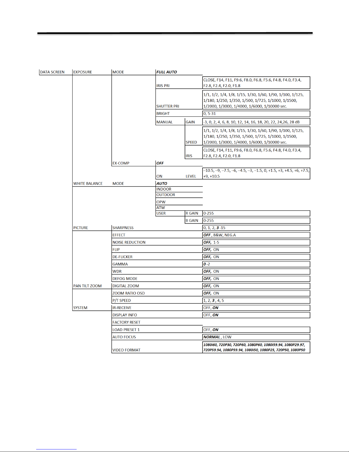
Menu Configuration
The menus of the camera are configured as described below. For more details, refer to the pages in
parentheses. The initial settings of each item are in bold.
Page 26
26
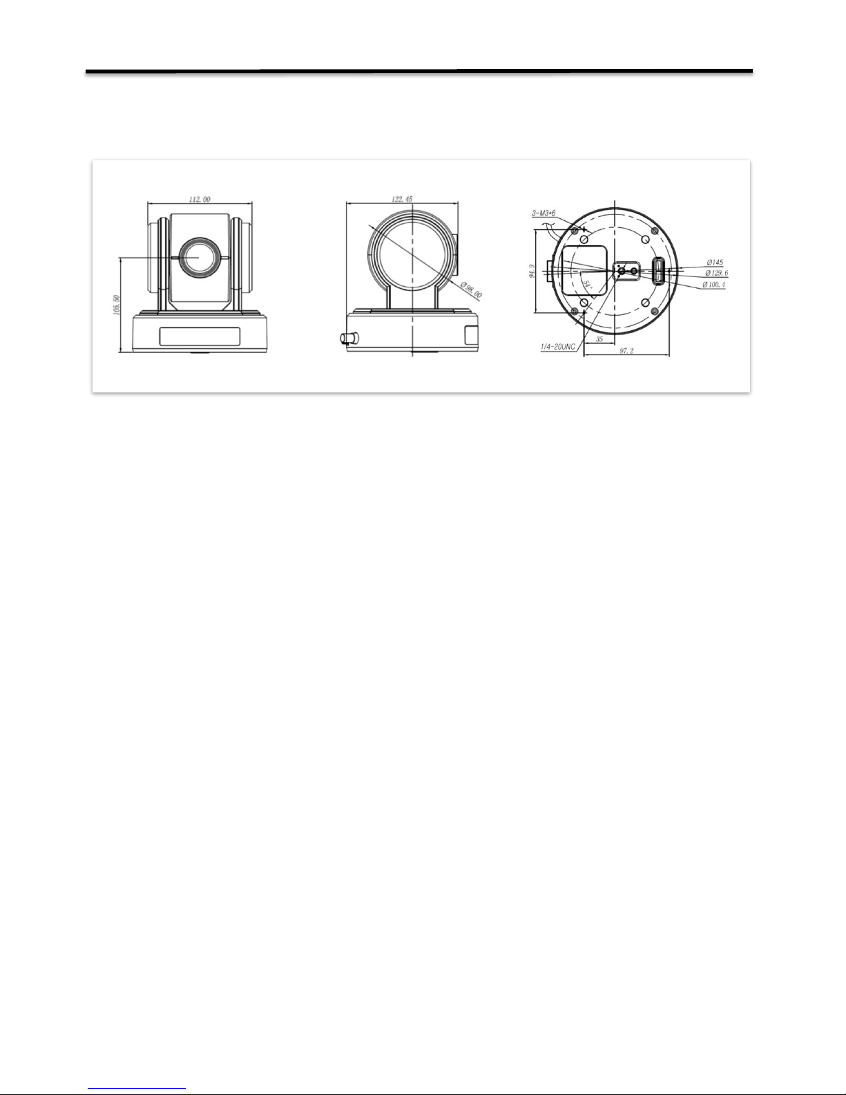
Dimension
Unit: mm
Page 27
27
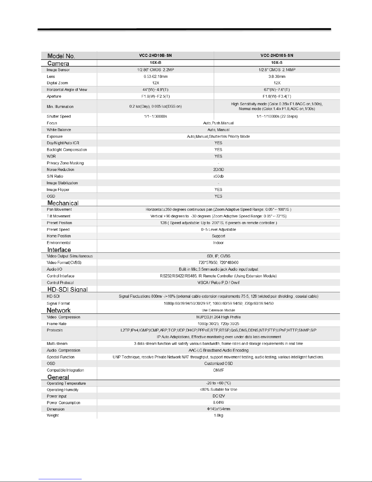
Specifications
Page 28
28
.
www.bolintechnology.com
2082 TECHNOLOGY LLC
dba
BOLIN TECHNOLOGY
 Loading...