

Page 1
1
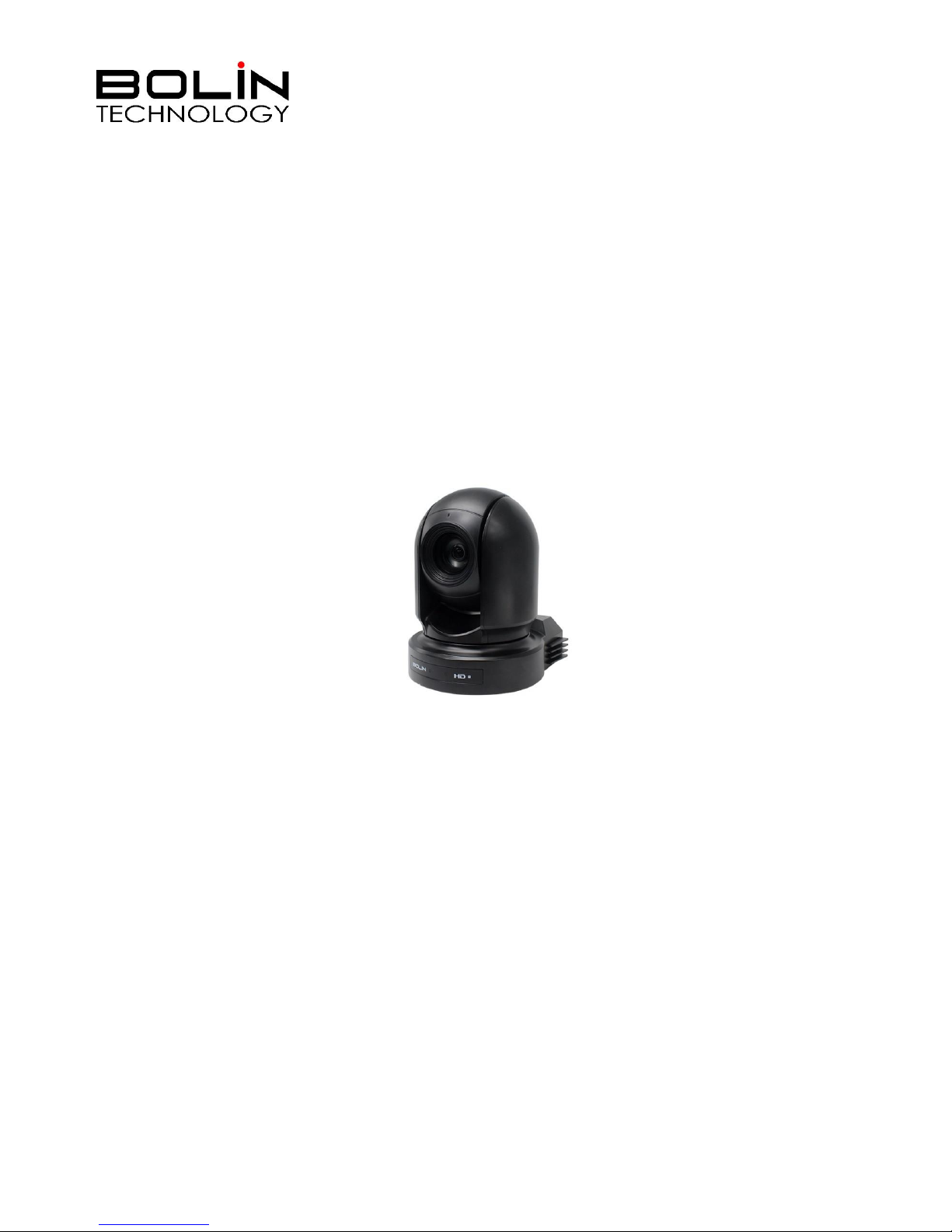
7 Series HD SDI+IP
Dual Output PTZ Camera
USER MANUAL
VERSION: VCC-7HD-M-12222018
VCC-7HD20S-3SMN
VCC-7HD30S-3SMN
© 2018 Bolin Technology
Page 2

2
Contents
IMPORTANT INFORMATION ..................................................................................................................................................... 3
WHAT’S IN THE BOX ................................................................................................................................................................. 6
OVERVIEW ................................................................................................................................................................................ 7
FEATURES ................................................................................................................................................................................. 7
CAMERA DIAGRAMS ................................................................................................................................................................. 8
REMOTE CONTROLLER ........................................................................................................................................................................ 9
SYSTEM CONFIGURATION ....................................................................................................................................................... 10
OBTAIN VIDEO SIGNAL ..................................................................................................................................................................... 11
AUDIO IN / OUT ............................................................................................................................................................................ 12
SD CARD ....................................................................................................................................................................................... 12
CAMERA CONTROL METHODS AND SYSTEM CONFIGURATIONS ............................................................................................. 13
USE THE INFRARED REMOTE CONTROLLER ............................................................................................................................................ 13
USE RS-232 (VISCA) ...................................................................................................................................................................... 13
USE RS-422(VISCA) / RS485 (PELCO P/D) ..................................................................................................................................... 15
RS422 (VISCA) CONNECTION ........................................................................................................................................................... 15
PELCO P/D KEYBOARD RS485 CONNECTION ...................................................................................................................................... 17
HOW TO MAKE THE CONNECTION WITH BOLIN PRODUCTS ...................................................................................................................... 18
VISCA OVER IP CONTROL ................................................................................................................................................................. 19
VISCA OVER IP NETWORK CONFIGURATION ......................................................................................................................................... 19
DIP SWITCH SETTINGS ............................................................................................................................................................ 20
ADJUSTING AND SETTING WITH MENUS................................................................................................................................. 22
EXPOSURE MENU ......................................................................................................................................................................... 23
WHITE BALANCE MENU ................................................................................................................................................................ 24
PICTURE1 MENU........................................................................................................................................................................... 25
PICTURE2 .................................................................................................................................................................................... 26
PAN TILT ZOOM MENU ................................................................................................................................................................. 26
SYSTEM MENU.............................................................................................................................................................................. 27
UPGRADING MCU FIRMWARE ........................................................................................................................................................... 28
OPERATION USING THE INFRARED REMOTE CONTROLLER ..................................................................................................... 29
PAN/TILT AND ZOOM OPERATION ...................................................................................................................................................... 29
OPERATING MULTIPLE CAMERAS WITH THE INFRARED REMOTE CONTROLLER .............................................................................................. 30
ADJUSTING THE CAMERA ................................................................................................................................................................... 30
STORING THE CAMERA SETTINGS IN MEMORY — THE PRESETTING FEATURE ............................................................................................... 31
MENU CONFIGURATION ......................................................................................................................................................... 32
DIMENSION ............................................................................................................................................................................ 33
Page 3

3
Operating Instructions
Thank you for purchasing our product. If there are any questions, please contact the authorized dealer.
Before operating the unit, please read this manual thoroughly and retain it for future reference.
Copyright
Copyright 2015-2018 Bolin Technology all rights reserved. No part of this manual may be copied, reproduced,
translated, or distributed in any form or by any means without prior consent in writing from our company.
Trademark Acknowledgement
and other Bolin's trademarks and logos are the property of Bolin Technology Other trademarks,
company names and product names contained in this manual are the property of their respective owners.
Trademarks and Registered Trademark Acknowledgement
Microsoft, Windows, ActiveX, and Internet Explorer are registered trademarks of Microsoft Corporation in the
U.S. and/or other countries.
HDMI, the HDMI logo and High-Definition Multimedia Interface are the trademarks or registered trademarks of
HDMI Licensing, LLC in the United States and other countries.
The Software may contain h.264/AVC video technology, the use of which requires the following notice from
MPEG-LA, L.L.C.:
THIS SOFTWARE IS LICENSED UNDER THE AVC PATENT PORTFOLIO LICENSE FOR THE PERSONAL AND
NON-COMMERCIAL USE OF A CONSUMER TO (I) ENCODE VIDEO IN COMPLIANCE WITH THE AVC
STANDARD ("AVC VIDEO") AND/OR (II) DECODE AVC VIDEO THAT WAS ENCODED BY A CONSUMER
ENGAGED IN A PERSONAL AND NON-COMMERCIAL ACTIVITY AND/OR WAS OBTAINED FROM A VIDEO
PROVIDER LICENSED TO PROVIDE AVC VIDEO. NO LICENSE IS GRANTED OR SHALL BE IMPLIED FOR
ANY OTHER USE. ADDITIONAL INFORMATION MAY BE OBTAINED FROM MPEG LA, L.L.C. SEE
http://www.mpegla.com.
HEVC/h.265 Covered by one or more claims of patents listed at patentlist.hevcadvance.com
HDBaseT is a trademark of the HDBaseT Alliance.
ONVIF trademarks and logos are to be used per the guidelines established in this and other ONVIF policies and
documents including the ONVIF Rules of Membership and the ONVIF Logo Guidelines1.
Other trademarks, company names and product names contained in this manual are the property of their respective
owners.
IMPORTANT INFORMATION
Legal Notice
Attention:
To ensure account security, please change the password after your first login. You are recommended to set a strong
password (no less than eight characters). Password login does not apply to some models that do not need password login.
The contents of this document are subject to change without prior notice. Updates will be added to the new version of this
manual. We will readily improve or update the products or procedures described in the manual.
Page 4
4
Best effort has been made to verify the integrity and correctness of the contents in this document, but no statement, information,
or recommendation in this manual shall constitute formal guarantee of any kind, expressed or implied. We shall not be held
responsible for any technical or typographical errors in this manual.
The product appearance shown in this manual is for reference only and may be different from the actual appearance of your
device.
This manual is a guide for multiple product models and so it is not intended for any specific product.
In this manual, the illustrations of displayed interface, parameters displayed, drawings and value ranges may vary with models.
Please see the actual product for details.
Due to uncertainties such as physical environment, discrepancy may exist between the actual values and reference values
provided in this manual.
Use of this document and the subsequent results shall be entirely on the user’s own responsibility.
Symbols
Symbol
Description
WARNING!
Contains important safety instructions and indicates situations that may cause bodily injury.
CAUTION!
User must be careful and improper operations may cause damage or malfunction of product.
NOTE!
Indicates useful or supplemental information about the use of product.
Safety Information
WARNING!
Installation and removal of the unit and its accessories must be carried out by qualified personnel. You must read all of
the Safety Instructions supplied with your equipment before installation and operation.
Warnings:
If the product does not work properly, please contact your dealer. Never attempt to disassemble the camera yourself.
(We will not assume any responsibility for problems caused by unauthorized repair or maintenance.)
This installation should be made by a qualified service person and should conform to all the local codes.
When shipping, the camera should be packed in its original packaging.
Make sure the power supply voltage is correct before using the camera.
Do not drop the camera or subject it to physical shock.
Do not touch sensor modules with fingers. If cleaning is necessary, use a clean cloth with a bit of ethanol and wipe it
gently. If the camera will not be used for an extended period of time, put on the lens cap to protect the sensor from dirt.
Do not aim the camera lens at the strong light such as sun or incandescent lamp. The strong light can cause fatal
damage to the camera.
Maintenance Precautions:
If there is dust on the front glass surface, remove the dust gently using an oil-free brush or a rubber dust blowing
ball.
If there is grease or a dust stain on the front glass surface, clean the glass surface gently from the center outward
Page 5
5
using anti-static gloves or an oil-free cloth. If the grease or the stain still cannot be removed, use anti-static
gloves or an oil-free cloth dipped with detergent and clean the glass surface gently until it is removed.
Do not use organic solvents, such as benzene or ethanol when cleaning the front glass surface.
Regulatory Compliance
FCC Part 15
This equipment has been tested and found to comply with the limits for digital device, pursuant to part 15 of the FCC
Rules. These limits are designed to provide reasonable protection against harmful interference when the equipment is
operated in a commercial environment. This equipment generates, uses, and can radiate radio frequency energy and, if
not installed and used in accordance with the instruction manual, may cause harmful interference to radio
communications. Operation of this equipment in a residential area is likely to cause harmful interference in which case
the user will be required to correct the interference at his own expense.
This product complies with Part 15 of the FCC Rules. Operation is subject to the following two conditions:
This device may not cause harmful interference.
This device must accept any interference received, including interference that may cause undesired operation.
LVD/EMC Directive
This product complies with the European Low Voltage Directive 2006/95/EC and EMC Directive
2004/108/EC.
WEEE Directive–2002/96/EC
The product this manual refers to is covered by the Waste Electrical & Electronic Equipment (WEEE)
Directive and must be disposed of in a responsible manner.
Page 6
6
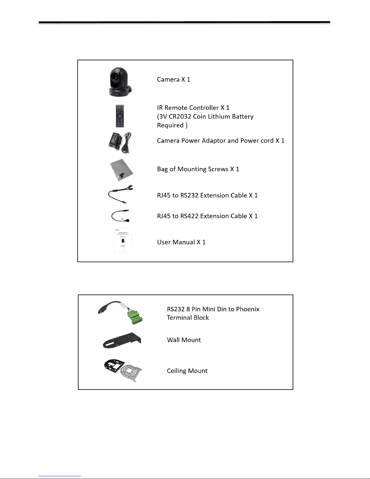
WHAT’S IN THE BOX
Note: The camera color may be in white or black per the item that is purchased.
Accessories (Optional)
Page 7

7
Overview
This user guide is suitable for the following models:
VCC-7HD20S-3SMN
VCC-7HD30S-3SMN
Features
Resolution: Up to 1080P60, 1080i59.94
IP Resolution: Up to 1080P60, 1080P30
Zoom: Optical 20X, 30X
Image stabilizer(20X) and true WDR 130dB
Video Output: HDMI, 3G-SDI, IP, CVBS simultaneously
±350-degree continuous pan, ±120-degree continuous tilt
128 presets, Speed up to 150 degrees/sec
Standard mounting and ceiling mounting with E-Flip function
Control supports RS-232 control, RS-422/485 control, VISCA-over-IP, IP-Onvif*, CGI*, IP control
software*, IR Remote Controller
Presets store camera directions and image parameters. (Up to 6 presets on remote controller or
128 presets via protocol programming.)
Image parameter setting restore with presets and quick access operation
IP Protocol RTSP, RTMP for online video streaming.
Local storage Micro SD card up to 32GB supported.
Supports Audio input, Audio output with IP streaming.
Power: DC 12V, PoE+(IEEE802.3at)
Firmware upgrade via USB2.0 or IP
*Features to be supported on future firmware release.
Page 8
8
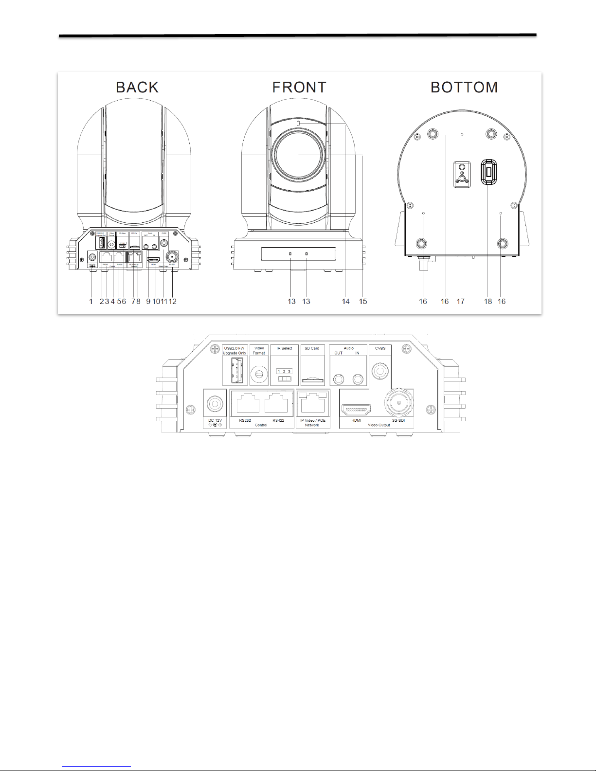
Camera Diagrams
1. 12V DC Power Port
Connect the supplied DC power adaptor and cord.
2. USB2.0 Port
For firmware upgrade only
3. RS232 Control Port (RJ45)
RJ45 to RS232 convertor cable is provided.
4. Video Format Selector
For video format selection
5. RS-422 Control Port (RJ45)
RJ45 to RS422 convertor cable is provided.
6. IR Remote ID Selector
Camera ID for IR remote controller
7. Micro SD Card Port
8. IP Network RJ45 Port
For VISCA over IP control and IP video streaming, with POE+(IEEE802.3at).
9. Audio Output/Input
10. HDMI Port (HDMI 1.4)
11. CVBS Video Output
12. 3G-SDI Video Output
13. IR Remote Controller Sensors
These are sensors to receive commands from infrared remote controller.
14. Power LED Indicator
Turns green when the camera is connected to power outlet. When the power is turned on, it takes about 15 to 30
seconds to display the image after LED turns on.
15. Lens
Page 9
9
This is a 20X/30X magnification optical zoom lens
16. Fix Mounting Holes
For original wall/ceiling mount bracket
17. Tripod mounting holes
18. Bottom DIP Switch
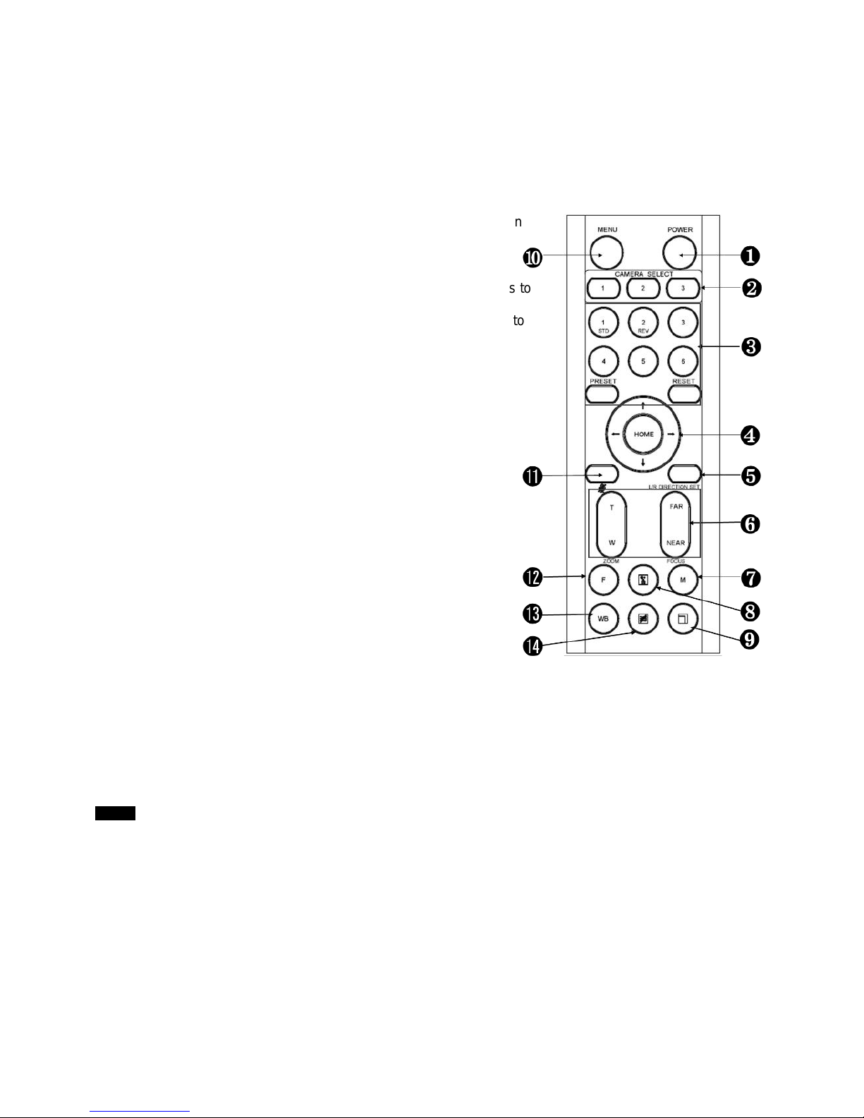
Remote Controller
1. Power
Power ON the camera to turn the camera in operation
status.
Power OFF the camera to turn the camera in
standby status.
When the camera is powered OFF, the camera turns to
the back and would be on standby mode.
When the camera is powered ON, the camera turns to
the front.
Powering the camera ON/OFF would not restart the
camera.
2. Camera ID (Total 3) Selector
3. Preset Position (Total 6) Calling and Setting
4. PAN-TILT
Pan and Tilt direction control
HOME: Home position, Resolution reset
5. L/R Direction Set
Left and right orientation setting
6. ZOOM/FOCUS
Far
Near
7. Auto/Manual Focus
8. Back Light
9. Video Format Switching
You can change the video format by keep pressing
the button. (When video format is changed, the
camera would restart and the screen turns black
for few seconds.)
10. MENU
On screen menu display ON/OFF
11. Audio Switch
You can turn the Mic built in the camera Off/ON by pressing the button once.
12. Fast/Slow Zooming Speed Switching
13. White Balance
Change the White Balance setting by pressing the button.
14. De-Flicker
When you find the video flicking, press the button once to eliminate the flickers.
Notes
3V CR2032 Coin lithium Battery is not included with the remote controller.
3V CR2032 Coin lithium batteries are not re-changeable.
Page 10
10
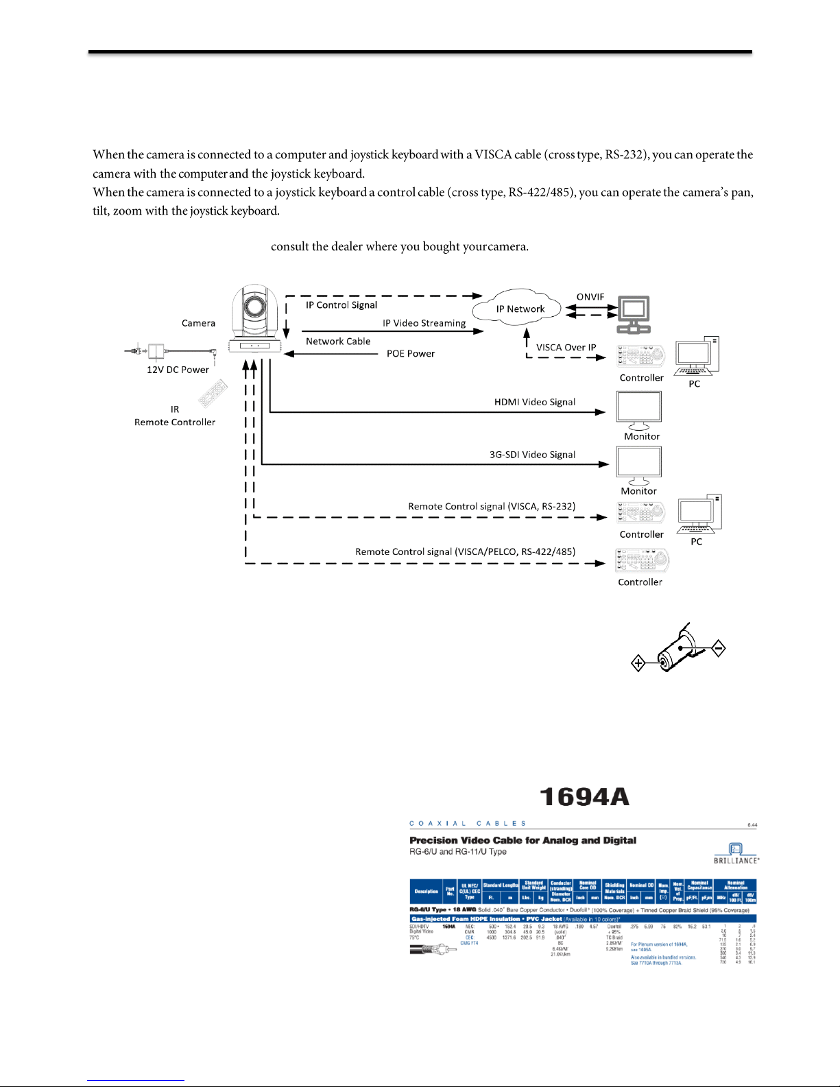
System Configuration
Connection
In this connection configuration, HDMI cable, SDI video cable, data cable, Network cable is required. To obtain these thirdparty components or accessories,
Power
Use only the DC power adaptor (JEITA type4) supplied with the unit. Do not use any
other DC power adaptor.
If using POE to power the camera, PoE+(IEEE802.3at) is supported
Ensure that the POE power source has sufficient power budget to power the camera, or some features may not
function properly.
Cable Requirements
Network Cable: 10/100 Mbps Ethernet CAT
5/5E/6 UTP cables are applicable to the
ANSI/EIA/TIA-568A/B and ISO/D. Eight
wires in the network cable need to be
inserted in parallel into the top of the cable
connector. The cable connector needs to be
crimped in position. When the cable
connector is in position, ensure that the metal
pieces of the cable connector are parallel to
each other and the clamp of the cable
connector is intact.
SDI Cable: For broadcast use,
Belden1694A/5CFB is a suitable cable to
transmit broadcast-quality video:
Page 11
11
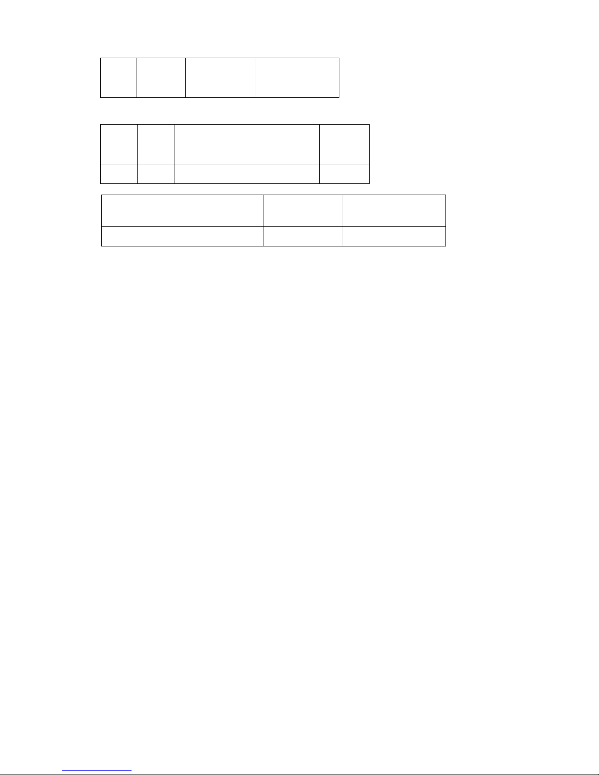
Conductor:
AWG
Stranding
Material
Nominal Diameter
18
Solid
Bare Copper
0.04 in.
Shield Material
Nom. Capacitance
Conductor to shield
Nom. Inductance
Nom. Char. Impedance
16.2 pF/ft
0.106 µH/ft
75 Ohm
Obtain Video Signal
The camera can simultaneously have SDI video output and HDMI video output and IP video output.
HDMI HD Video signal
1. Connect the camera to a HD monitor/TV using HDMI cable.
2. Turn on the camera, video will display on the monitor after running initializing.
3. Information of the camera initial setting status will display for 5 seconds.
4. You can set the video format of the camera to the one you want to display.
SDI Video Signal
The camera can simultaneously stream SDI video output with HDMI video output.
1. Connect SDI cable in between the camera your SDI Device/display.
2. You now have SDI video output.
3. SDI video only supports 1080P.
IP Video Signal
The camera can simultaneously stream IP video output and SDI video output and HDMI video output.
1. Connect the camera to the network using Cat5/Cat6 network cable.
2. You need to have a web browser or VMS client software ready for IP video streaming.
3. PELCO address and Baud Rate setting on the camera must be as same as the setting on camera IP WEB
interface.
4. To obtain IP video and configure IP video, please refer to Network Camera User Manual Part Two.
CVBS Video Signal
1. Connect CVBS cable in between the camera and your CVBS Device/display.
2. You now have CVBS video output.
Camera Initial setting status Information
Type
Layer
Material
Coverage
Tape
1
Aluminum / Polyester / Aluminum
100%
Braid
2
Tinned Copper
95%
Page 12
12
Information of the camera initial setting status will display for 5 seconds.
1. Camera PELCO ID for RS-485 control
2. Camera ID for IR Remote Controller
3. IR remote control signal receive current setting
4. Baud Rate current setting
5. Control COMM Port current setting
6. Video format current setting
7. HDMI current setting
8. Model number
9. Firmware version
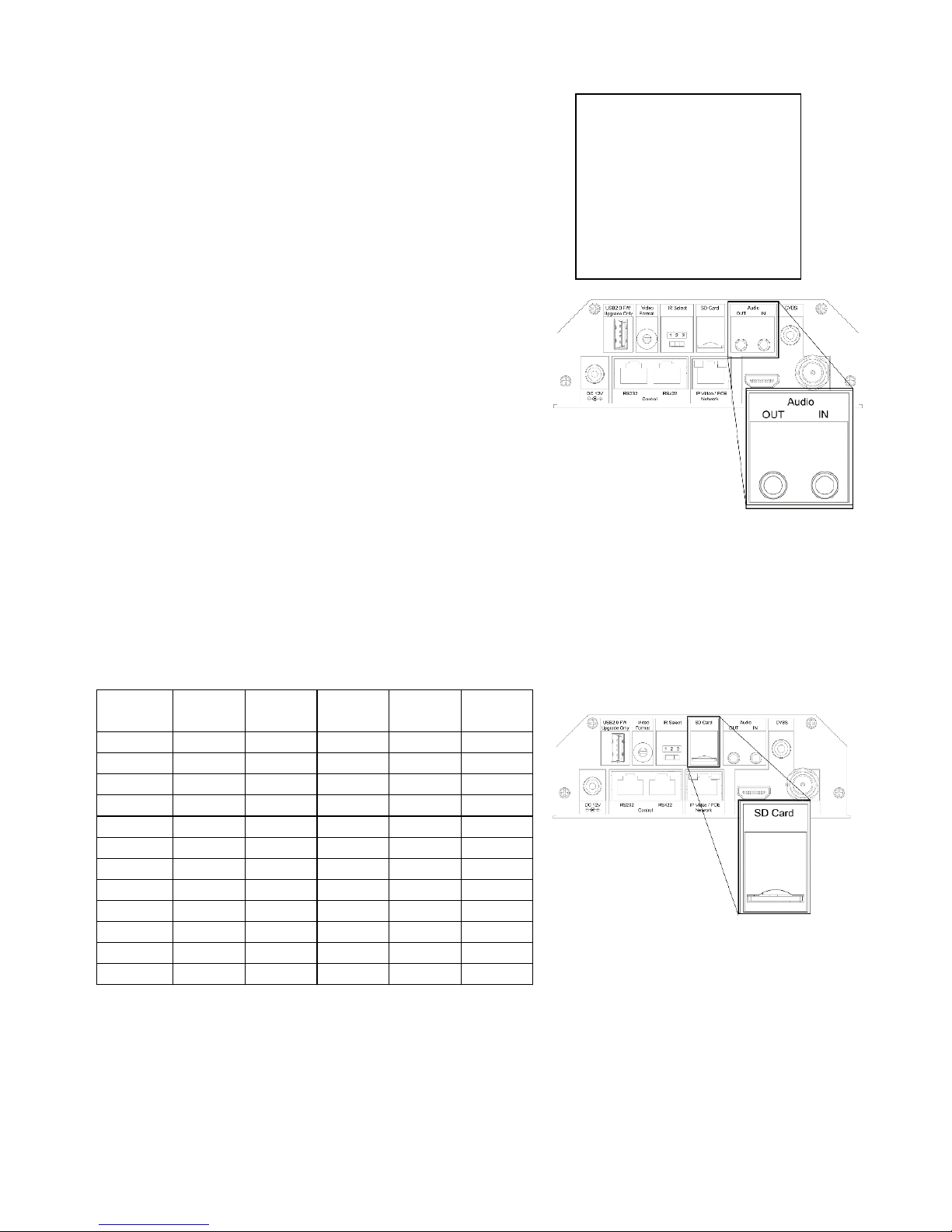
Audio IN / OUT
A microphone can be connected to the Audio IN port, which
feeds audio into the camera
A speaker can be connected to the Audio OUT port, which
will output any audio that is captured on the Audio In port
See Manual part 2 for more information about Audio capture
SD Card
Micro SD card can be inserted to the camera for local recording.
Ensure that the Micro SD card’s pins are faced downward (logo faced up)
Slide the card into the slot, and click into place
To remove the card, click inward, and it will pop outward and may be removed
See Manual part 2 for more information regarding SD recording
Currently, the following Micro SD cards are supported:
Brand Size Format Type Class
Transfer
Bus
Kingston 16GB exFAT SDHC 10 IU1
Kingston 32GB FAT32 SDHC 10 IU1
Kingston 32GB exFAT SDHC 10 IU1
Kingston 64GB exFAT SDXC 10 IU1
Kingston 128GB exFAT SDXC 10 IU1
Samsung 32GB FAT32 SDHC 10 UHS-I (1)
Samsung 32GB exFAT SDHC 10 UHS-I (1)
Samsung 32GB FAT32 SDHC 10 UHS-I (1)
Samsung 32GB exFAT SDHC 10 UHS-I (1)
Samsung 64GB exFAT SDXC 10 UHS-I (3)
Toshiba 32GB FAT32 NA 10 U1
Toshiba 32GB exFAT NA 10 U1
PELCO ID 001
IR ID 01
IR-RECEIVE ON
BAUD RATE 9600
COMM TYPE 422
FORMAT 1080P29.97
HDMI OUT YUV
MODEL TYPE ---SV: V0B1100S36040AD04
Camera Status Info Display
Page 13
13
Camera Control Methods and System Configurations
This unit has multiple ways of controlling the camera and various system configuration capabilities using optional
products. This section describes the ways of controlling and typical system examples with the required components and
usage of each system.
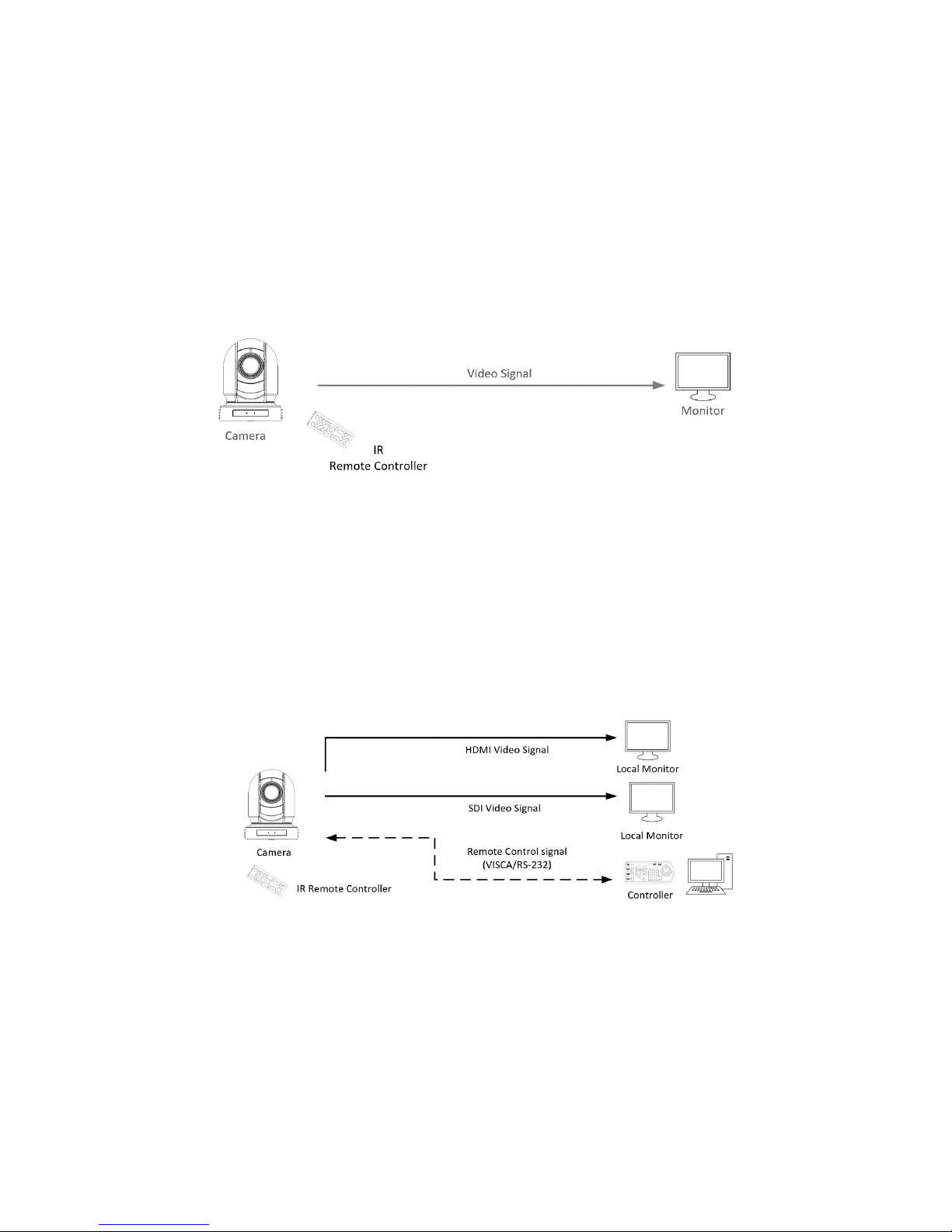
1. Use the Infrared Remote Controller
2. Use RS-232 (VISCA)
3. Use RS-422/485 (VISCA/PELCO P/D)
4. IP Control (See Network Camera User Manual)
Use the Infrared Remote Controller
To operate the camera from a short distance.
For IR remote control details, refer to Operation Using the Infrared Remote Controller.
Use RS-232 (VISCA)
You can use RS-232 port to connect to optional controllers, such as joystick control keyboard, control PC station, to
operate the camera.
To perform pan/tilt and zoom operations using the joystick of the control keyboard, and to perform the Preset operation
using the control buttons.
An application software that supports this unit is needed if you use PC station.
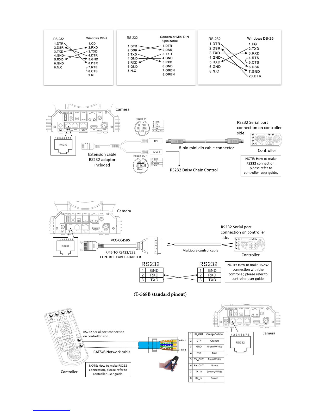
RS232 Connection
1. Set RS232 control method on Bottom Dip Switch.
2. Set Baud Rate on Bottom Dip Switch to the same as Baud Rate setting on the keyboard you are using.
3. Set specific camera address that you want to control the camera for on Bottom Dip Switch.
4. If you want to have the camera address to be automatically assigned by VISCA controller, set camera Dip Switch address to
0.
5. Reboot the camera by turning it Off/On after the Bottom Dip Switch has been set up correctly.
6. Camera supports Daisy Chain connection up to 7 cameras.
7. Use the RJ45 to RS232 (VISCA) control cable. The controller must be VISCA compatible.
Page 14
14
8. You can make RS232 connection cable if you have the following applications:
9. Use extension cables included RJ45 to RS232 8 pin Mini Din adaptor to make RS232 connection for your control device.
10. Use extension cables included RJ45 to RS422/232 Phoenix terminal contact adaptor to make RS232 connection for your
control device.
11. Or you can use CAT5/6 network cable to make RS232 connection by following the
pin definition below:
Page 15
15
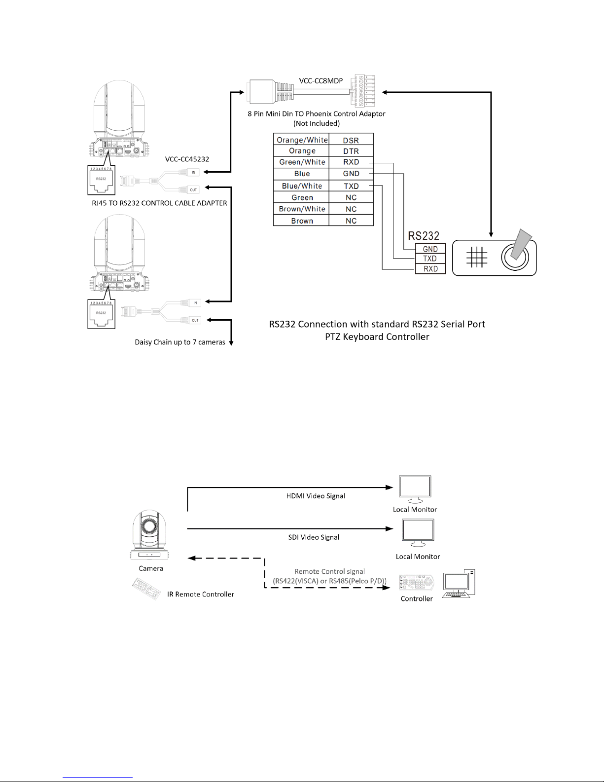
12. How to make RS232 Daisy Chain multiple camera connection with standard RS232 serial port controller as
below:
Use RS-422(VISCA) / RS485 (PELCO P/D)
You can use RS-422/485 port connect to optional controllers, such as joystick control keyboard, control PC station, to
operate the camera.
To perform pan/tilt and zoom operations using the joystick of the control keyboard, and to perform the Preset operation
using the control buttons.
An application software that supports this unit is needed if you use PC station.
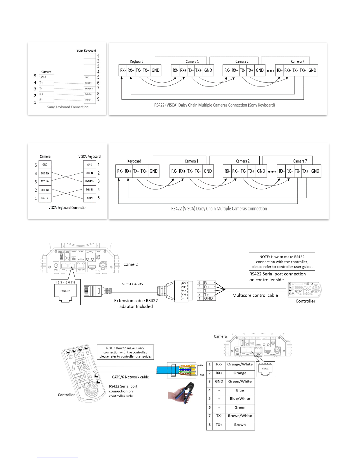
RS422 (VISCA) connection
1. Set RS422 control method on Bottom Dip Switch.
2. Set Baud Rate on Bottom Dip Switch to the same as Baud Rate setting on the keyboard you are using.
3. Set specific camera address that you want to control the camera for on Bottom Dip Switch.
4. If you want to have the camera address to be automatically assigned by VISCA controller, set camera Dip Switch address to
0.
5. Reboot the camera by turning it Off/On after the Bottom Dip Switch has been set up correctly.
6. Use the RJ45 to RS422 control cable. The controller must be VISCA compatible.
7. Camera supports Daisy Chain connection up to 7 cameras.
8. The connection of SONY keyboard is different than other VISCA (Non-Sony) keyboard.
Page 16
16
9. How to make RS422 connection and RS422 Daisy Chain multiple cameras connection with SONY controller as below
SONY Keyboard RS422 Connection
10. How to make RS422 connection and RS422 Daisy Chain multiple cameras connection with Non-Sony controller as below:
VISCA (Non-Sony) Keyboard RS422 Connection
11. Use extension cables RJ45 to RS422 Phoenix connecter adaptor included to make RS422 connection for your control device.
12. Or you can use CAT5/6 T-568B Standard Ethernet cable direct connect between the camera and the controller to make
RS422 connection by following the pin definition below:
Page 17
17
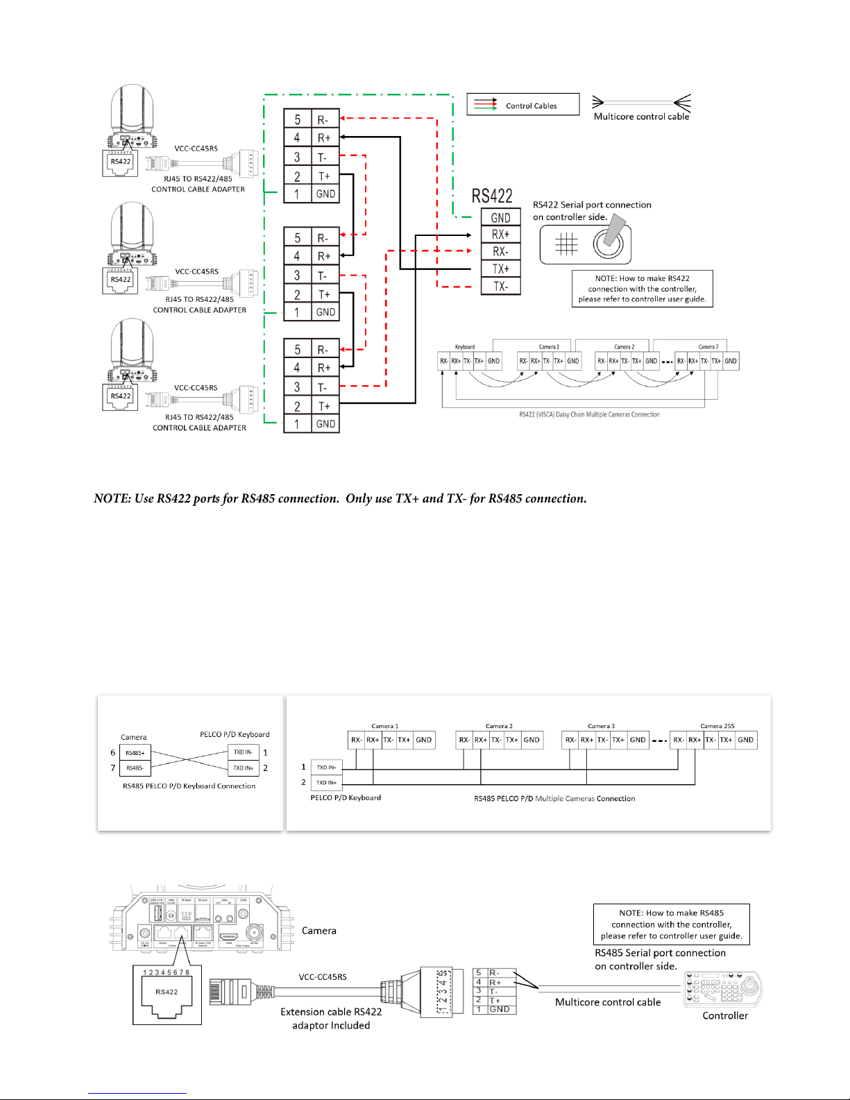
13. How to make RS422 Daisy Chain multiple camera connection with RS422 standard serial port controller:
PELCO P/D Keyboard RS485 Connection
Set RS422 control method on Bottom Dip Switch.
Set Baud Rate on Bottom Dip Switch to the same as Baud Rate setting on the keyboard you are using.
Set the camera ID on OSD menu by remote controller
Reboot the camera by turning it Off/On after the Bottom Dip Switch has been set up correctly.
Use PELCO P/D compatible keyboard.
Use preset 95# on the keyboard to bring up/exit camera OSD menu.
Use joystick and Button “OPEN” or “CLOSE” to navigate OSD menu.
To operate keyboard, please refer to the user manual of the keyboard you are using.
PELCO RS485 Connection
Use extension cables included RJ45 to RS422 Phoenix connecter adaptor to make RS485 connection for your control device.
Page 18
18
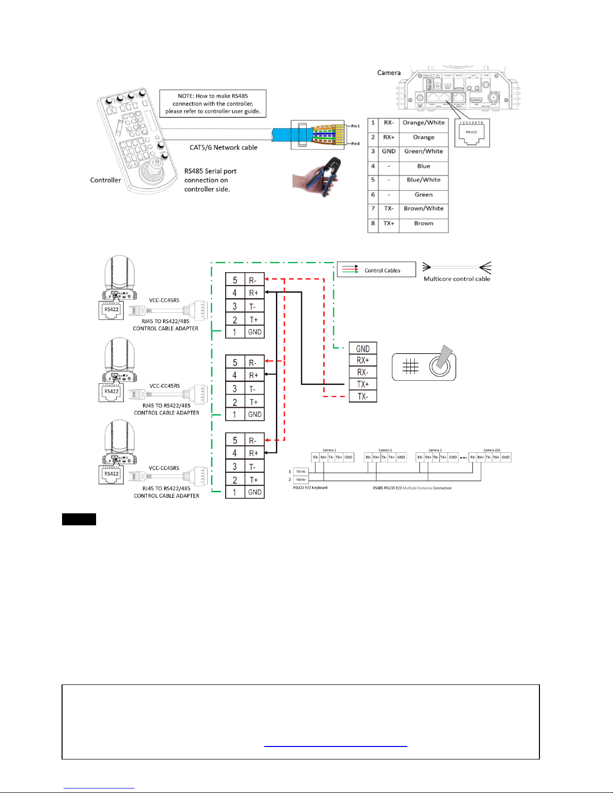
Or you can use CAT5/6 T-568B Standard Ethernet cable direct connect between the camera and the controller to make
RS485 connection by following the pin definition below:
How to make RS485 multiple cameras connection with RS485 standard serial port controller:
Note
For RS-232 VISCA control, this unit supports daisy chain connection for using multiple cameras.
For control details, refer to Operating Instructions of control keyboard/station software.
You need to match the communication speed (Baud Rate) between the camera and the joystick controller.
You cannot use the RS-232 connections while you are using the RS422/485 connection.
Operating Multiple Cameras Using RS-232,422/485
Using RS-232 (VISCA), you can connect to 7 cameras.
Using RS-422 (VISCA), you can connect to 7 cameras.
Using RS-485 (PELCO), you can connect to 255 cameras.
Using RS-485 (PELCO), all camera addresses must be set up before the connection. You can set the camera
address by operating OSD menu, or by setting the Dip Switch on the bottom of the camera. In this case, you can
use multiple control keyboards.
How to make the connection with BOLIN products
Please see the User Guide “BOLIN Camera and Keyboard Controller Connection”
that you can download it at www.bolintechnology.com product pages.
Page 19
19
VISCA over IP Control
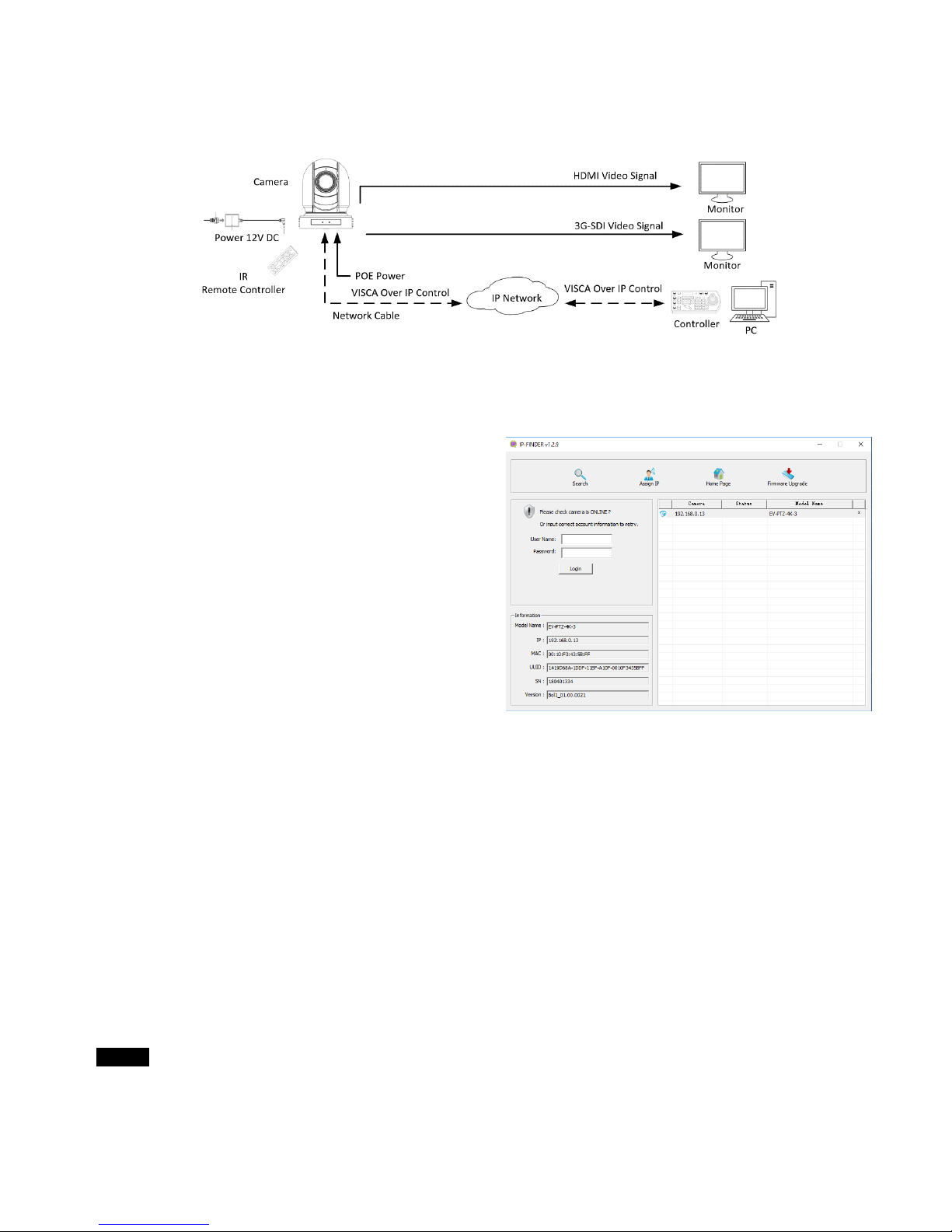
With VISCA over IP function, you can control the camera using VISCA protocol on a controller equipped with
IP communication capabilities via LAN.
The communication specifications of VISCA over IP are followings:
Interface: RJ-45 10/100M
Interface protocol: IPv4
Transport protocol: UDP
IP address: 192.168.0.13 By default
Port: 52381
VISCA over IP Network Configuration
Re-assign the camera
The default information of the IP camera is following:
Static IP: 192.168.0.13
Subnet mask: 255.255.255.0
Gateway: 192.168.0.1
VISCA over IP control port: 52381.
The camera IP address needs to be assigned to the IP address that works with your local network.
Controlling via VISCA over IP
Connect the network port on the camera to the network switch.
Set the IP address and other network information appropriately to communicate on your network
Connect the VISCA over IP-compatible controller to the network
Configure the controller to access the camera’s IP address and VISCA over IP port
The IP port within on your control must be set to 52381 to communicate with the camera.
Select VISCA protocol on your IP control device.
Recommended way to re-assign the IP address:
1. Create a local network within which the camera and your PC/Laptop are connected.
2. Install and run the IP-FINDER tool (You can contact Bolin Technical support team for tool requirements)
3. The IP-FINDER can find the camera IP address, which is the default :192.168.0.13
4. Click the search button, select the camera you want to Assign IP address, edit the IP address to the one that matches your
local network credential.
5. Once the IP address has been changed successfully, you can access the IP camera via your local network.
Note
How to re-assign the IP address to the camera, please refer to user manual Part Two-IP Camera user
guide.
Page 20
20
DIP SWITCH SETTINGS
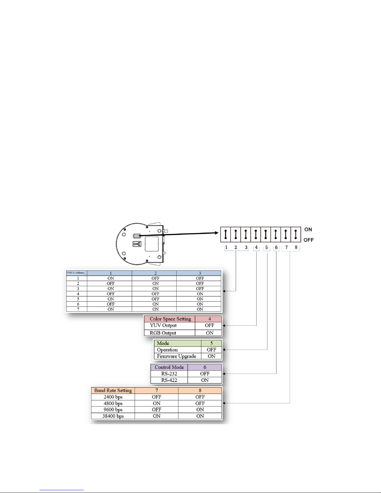
The Dip switches are for setting the camera configuration for following items:
1. Camera ID Address for RS-485 PELCO protocol
2. Video output / Video color space
3. RS-232 / RS-422/485 selection
4. RS-232 / RS-422/485 baud rate
5. Video resolutions selection
6. IR remote controller ID
Setting of the BOTTOM DIP Switches
Turn off power to the camera before changing the DIP switch settings.
Power on the camera to have the new Dip Switch setting activated.
From the above list, No.1 Camera ID address and NO.2 Video resolution settings can be set in camera OSD menu as
well. The camera takes either the way of OSD menu setting or the way of bottom DIP switch setting. They override each
other. After the camera is turned on, the camera takes the last setting before it is turned on, either set through the OSD or
bottom DIP switch.
The Bottom DIP Switch Settings
Bit 1~3: Camera Address setting for VISCA protocol
Bit 4: Video Output/Video Color Space
Bit 5: Reserve
Bit 6: RS-232/RS-422
Bit 7~8: RS-232/RS-422 Baud Rate
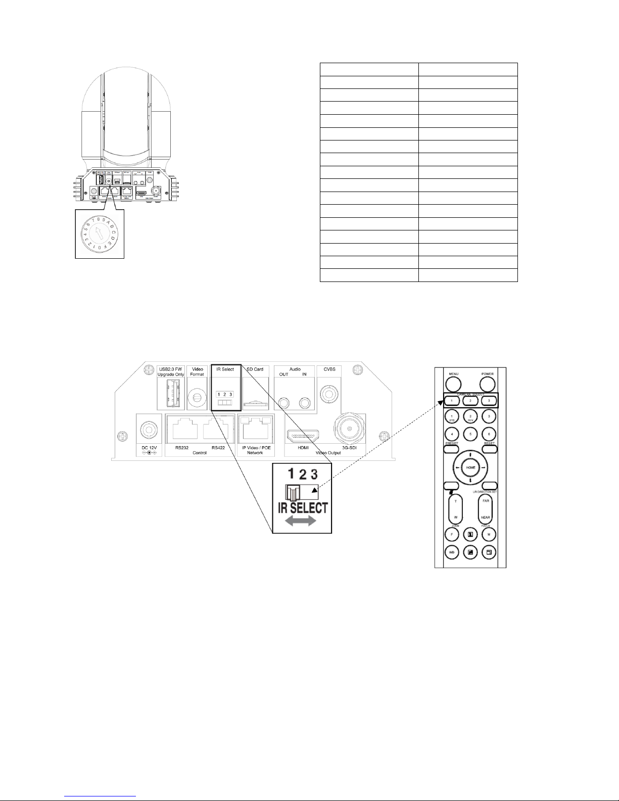
Setting of the back panel Rotate DIP Switches
The Rotate Dip Switch is for setting video format.
Use small screw driver to turn the switch, the arrow points to the Numbers or the Letters. The video format that the
Number or Letter stands for refer to the video format as the chart following:
Page 21
21
IR Remote Controller ID Setting
Set the IR SELECT switch on the back panel of the camera to 1, 2 or 3, which is the camera ID number that you want to
operate on the Remote Controller.
Numbers & Letters
Video Resolution
0
1080i59.94
1
1080P29.97
2
720P59.94
3
1080P59.94
4
1080P50
5
1080I60
6
1080P30
7
1080P60
8
1080I50
9
1080P25
A
720P50
B
1080P50
C
720P25
D
720P30
E
720P60 F -
Page 22
22
Adjusting and Setting with Menus
About On-Screen Menus
You can change various settings, such as shooting conditions and system setup of the camera, while observing menus
displayed on a connected computer screen.
This section explains how to read the on-screen menus before starting menu operations.
The menu parameters may vary according to the different product model numbers.
For a complete configurations menu, see “Menu Configuration” (page 25).
Note
You cannot perform pan/tilt operations while the menu is displayed.
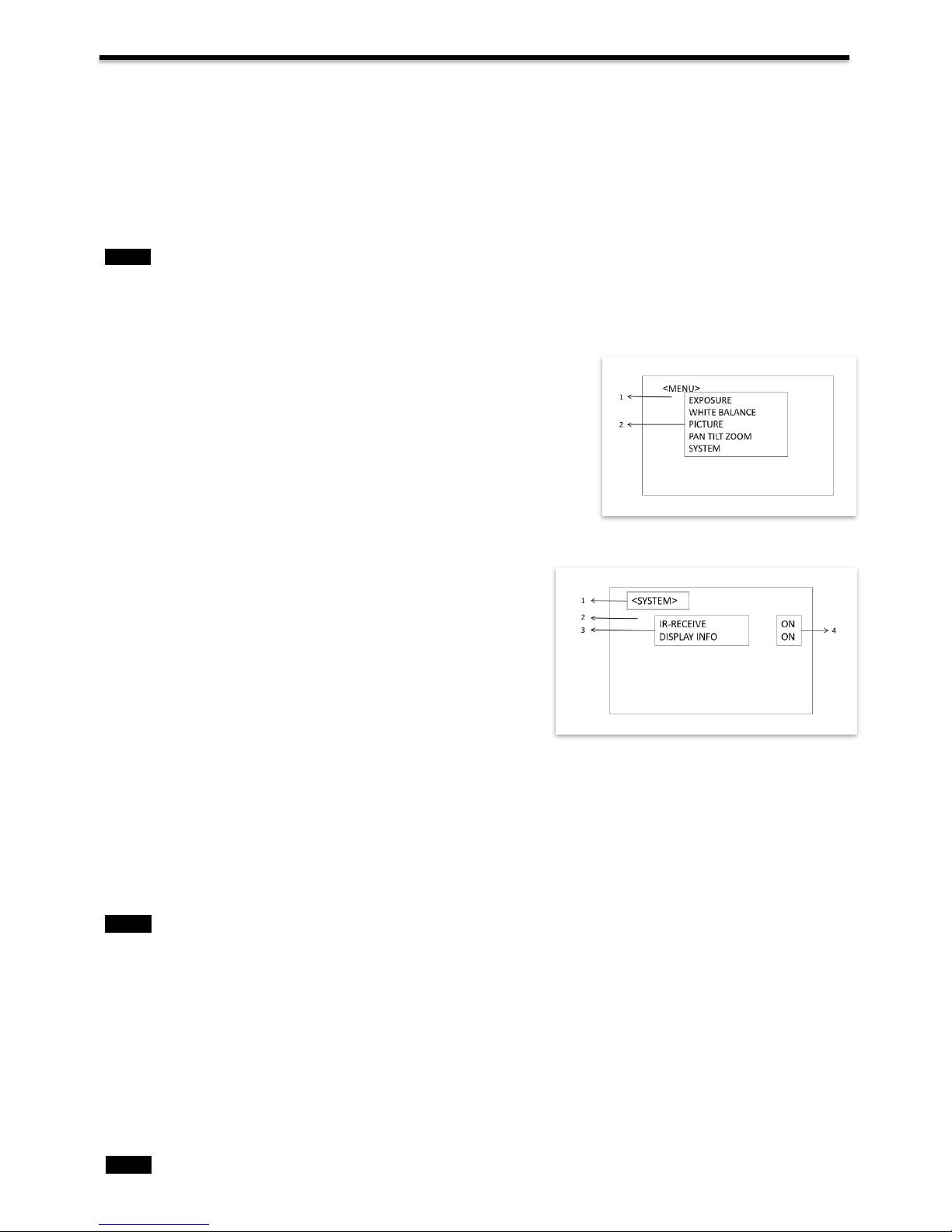
Main Menu
To display the main menu, press the DATA SCREEN button on the supplied infrared remote controller.
1.
Selected Items
Selects a setting menu.
The selected item is shown by the cursor. The cursor moves up or down by
pressing the “↑, ↓” button on the infrared remote controller.
2.
Menu Items
To display a setting menu, select one using the “↑, ↓” button on the infrared
remote controller and press the HOME button on the infrared remote
controller.
Setting Menus
The setting menu selected on the main menu is displayed.
1.
Setting Menu
The name of the setting menu currently selected is displayed here.
2.
Selected Item
Selects a setting item.
The selected item is shown by the cursor.
Move the cursor up or down by pressing the “↑, ↓” button on the
infrared remote controller.
3.
Setting Items
The setting items for this setting menu are displayed. Select the setting item using the “↑, ↓” button on the infrared remote
controller.
4.
Set Value
The currently set values are displayed.
To change a set value, use the “←, →” button on the infrared remote controller.
In some product models, only use “←” button on the infrared remote controller to change the value. To confirm the value,
you can use either “→” button or HOME button.
Control Button
You can select the item by pressing “↑, ↓, ←, →” and HOME button.
1.
You can select a menu item by
“↑, ↓”
button on the infrared remote
controller
. The selected item is shown by the
cursor (Color change).
You can change the value of the item by pressing “←, →” button.
2.
You can move to the next layer by
pressing the HOME button.
3.
You can return to the normal display by
pressing the DATA SCREEN button.
Note
Note
Page 23
23
When you are operating the menu using the infrared remote controller, you cannot set IR- RECEIVE in the SYSTEM
menu to OFF. To set IR- RECEIVE to OFF, use the appropriate VISCA command.
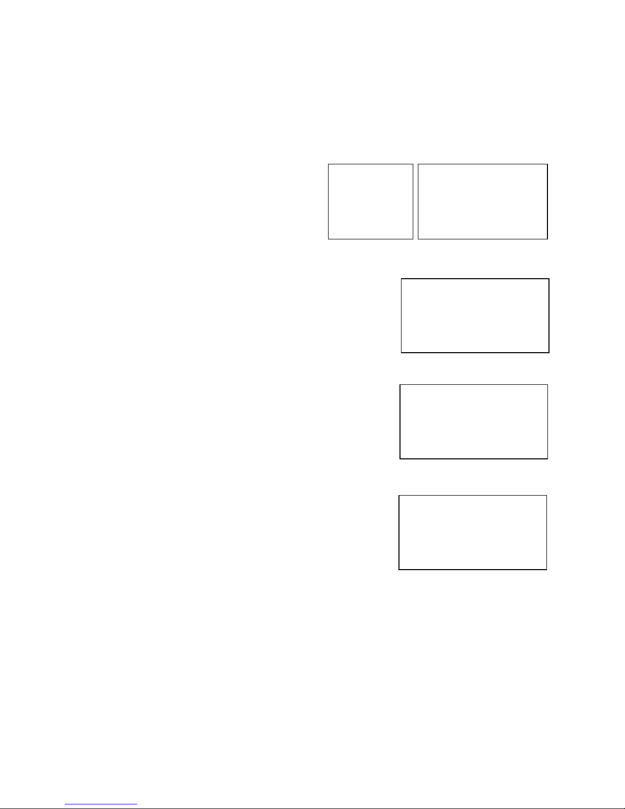
EXPOSURE Menu
The EXPOSURE menu is used to set the items related to exposure.
MODE (Exposure Mode)
FULL AUTO: The exposure is adjusted
automatically using the values set for SLOW
SHUTTER, S. SHUTTER LIMIT, AE RESPONSE,
GAIN LIMIT, and EX-COMP.
MANUAL: Adjust the GAIN, GAIN LIMIT,
electronic shutter speed (SPEED), iris (IRIS), and
HIGH SENSITIVITY manually.
IRIS PRI: Iris Priority mode. The exposure is
adjusted automatically using the values manually set
for iris (IRIS), GAIN LIMIT, and EX-COMP
SHUTTER PRI: Shutter Priority mode. The exposure is adjusted
automatically using the values manually set for electronic shutter
speed (SPEED), GAIN LIMIT, and EX-COMP
When you select one from various exposure modes, some of the following
setting items that are required for the selected mode will appear.
GAIN: Select the gain from the following:
0dB, 3.6 dB, 7.1 dB, 10.7 dB, 14.3 dB, 17.8 dB, 21.4 dB, 25 dB, 28.6 dB,
32.1 dB, 35.7 dB, 39.3 dB, 42.8 dB, 46.4 dB, 50 dB
GAIN LIMIT:
The gain limit can be set at Full Auto, Shutter Priority, Iris Priority,
Bright, Spot Exposure and Manual in AE mode. Use this setting when
you want to obtain images with a focus on the signal-to-noise ratio
HIGH SENSITIVITY:
This function increases the max gain to allow bright output in darker
environments. However, with a strong gain (up to 10×), the captured
image will contain a lot of noise
SPEED: Select the electronic shutter speed from the following:
When video format is set to 720P25, 1080P50, 1080i50, 1080P25, 720P50,
Speed can be selected from the following:
1/1, 1/2, 1/3, 1/6, 1/12, 1/25, 1/50, 1/75, 1/100, 1/120, 1/150, 1/215, 1/300,
1/425, 1/600, 1/1000, 1/1250, 1/1750, 1/2500, 1/3500, 1/6000, 1/10K.
When video format is set to 720P30, 1080i59.94, 1080P29.97, 720P59.94, 1080P59.94, 1080I60, 1080P30, 1080P60,
720P60, Speed can be selected from the following:
1/1, 1/2, 1/4, 1/8, 1/15, 1/30, 1/60, 1/90, 1/100, 1/125, 1/180, 1/250, 1/350, 1/500, 1/725, 1/1000, 1/1500, 1/2000, 1/3000,
1/4000, 1/6000, 1/10K.
IRIS: Select the iris the following: CLOSE, F14, F11, F9.6, F8.0, F6.8, F5.6, F4.8, F4.0, F3.4, F2.8, F2.4, F2.0, F1.6
SLOW SHUTTER:
When set to “On,” the slow shutter functions automatically when the light darkens. This setting is available
only when the AE mode is set to “Full Auto.” The initial setting is “Auto Slow Shutter Off.”
S. SHUTTER LIMIT:
When the subject becomes dark, the shutter speed becomes slow and the gain is increased. This is a function
to put a limit on the shutter speed. It prevents the camera shake when you shoot a moving subject in a dark
place.
MODE MANUAL
GAIN 12dB
GAIN LIMIT 21.4dB
SPEED 1/60
IRIS F1.6
HIGH SENSITIVITY OFF
EXPOSURE MENU: MANUAL
>EXPOSURE
>WHITE BALANCE
>PICTURE
PAN TILT ZOOM
>SYSTEM
OSD
MODE FULL AUTO
SLOW SHUTTER OFF
S. SHUTTER LIMIT 1/4
AE RESPONSE 01
GAIN LIMIT 21.4dB
>EX COMP OFF
EXPOSURE MENU: FULL AUTO
MODE IRIS PRI
IRIS F1.6
GAIN LIMIT 21.4dB
EX-COMP OFF
EXPOSURE MENU: IRIS PRI
MODE SHUTTER PRI
SPEED 1/60
GAIN LIMIT 21.4dB
EX-COMP OFF
EXPOSURE MENU: SHUTTER PRI
Page 24
24
AE Response:
The slow AE Response function allows you to reduce the exposure response speed. Usually the camera is set
up so that the optimum exposure can be obtained automatically within about 1 second. However, using the
slow AE response function allows you to lengthen the auto exposure response speed from the initial setup
speed
EX-COMP: (Exposure Compensation)
When MODE is set to one of FULL AUTO, SHUTTER PRI or IRIS PRI, set this item to ON to enable exposure
compensation. When you set EX-COMP to ON, LEVEL appear and you can select the exposure compensation
level from the following:
–10.5, –9, –7.5, –6, –4.5, –3, –1.5, 0, +1.5, +3, +4.5, +6, +7.5, +9, +10.5
If you set the level to 0, exposure compensation will be disabled. Level +10.5 is the brightest and –10.5 is the
darkest compensation value.
When EX-COMP is set to OFF, exposure compensation does not function.
WHITE BALANCE Menu
The WHITE BALANCE menu is used to select the white balance mode.
MODE (white balance mode)
Select the white balance mode from the following:
AUTO: This mode computes the white balance
value output using color information from the entire
screen. It outputs the proper value using the color
temperature radiating from a black subject based on
a range of values from 2500K to 7500K. This mode
is the initial setting.
INDOOR: 3200K Base Mode
OUTDOOR: 5800K Base Mode
OPW (One Push White Balance): The One Push White Balance
mode is a fixed white balance mode that may be automatically
readjusted only at the request of the user (One Push Trigger),
assuming that a white subject, in correct lighting conditions, and
occupying more than 1/2 of the image, is submitted to the camera.
One Push White Balance data is lost when the power is turned off. If
the power is turned off, reset One Push White Balance.
NOTE: When you select the OPW (One Push White
Balance)
Perform the following operations:
1. Place an image of white subject (For example: A piece of
white paper) in the center of the screen.
2. Press the HOME button of the infrared remote controller.
The one-push white balance adjustment is activated.
ATW (Auto Tracking White Balance): Auto Tracking White
balance (2000K to 10000K), allows the camera to adjust the tone
according to the temperature of the light source illuminating the
subject
EXPOSURE
>WHITE BALANCE
>PICTURE
PAN TILT ZOOM
>SYSTEM
OSD
WB MODE AUTO
>
WHITE BALANCE MENU
WB MODE INDOOR
WHITE BALANCE MENU
WB MODE OUTDOOR
WHITE BALANCE MENU
WB MODE OPW
WHITE BALANCE MENU
WB MODE ATW
WHITE BALANCE MENU
Page 25
25
USER: This is a mode that enables you to manually set the control of
R and B gain up to 256 steps.
NOTE: When you select USER, R. GAIN (red gain) and B. GAIN
(blue gain) appear. You can select each item in the range from 0 to
255.
OUTDOOR AUTO: This is an auto white balance mode specifically
for outdoors. It allows you to capture images with natural white
balance in the morning and evening.
SL AUTO: Sodium Vapor Lamp Auto: This is an auto white balance
mode that is compatible with sodium vapor lamps.
SL: Sodium Vapor Lamp: This is a fixed white balance mode
specifically for sodium vapor lamps.
SLO AUTO: Sodium Vapor Lamp Outdoor Auto: This is an auto
white balance mode specifically for outdoors, which is compatible with
sodium vapor lamps.
PICTURE1 Menu
SHARPNESS:
Picture sharpness value ranges from 0 to 15. You can enjoy
emphasized edge and high-resolution images.
EFFECT: (Picture Effect)
It consists of the following functions:
Image effect from Off, B&W
NOISE REDUCTION:
Noise reduction - you can enjoy clearer images by removing
unnecessary noise. You can select 6 levels from OFF
(MIN), 1 to 5 (MAX).
FLIP:
Image E-Flipper – Used when ceiling mounting or upright mounting. Set to OFF is upright mode, set to ON is for ceiling
mount.
MIRROR:
You can have the image as seen in a mirror, with the right side as though it were the left.
DE-FLICKER:
You can turn it ON if the Video output format frame rate is difference from your country’s electricity Frequency.
WDR: (Wide dynamic range mode): WDR feature is available on certain product models.
Wide Dynamic: ON, OFF. The camera distinguishes light and dark areas within the same scene, adjusts the brightness
for dark areas, and also controls the blown-out highlights.
You can select the wide dynamic range mode between ON and OFF
COLOR
You can configure the color gain from 1-15. Use this setting when bright color is particularly important.
HUE
You can adjust color phase from 1-15.
CONTRAST
You can adjust the contrast level in the range from 0 (00h) to 255 (FFh). The initial setting is 128 (80h). The smaller the
value is, the lower the contrast becomes, and the larger the value is, the higher the contrast becomes.
WB MODE USER
R GAIN 106
B GAIN 217
WHITE BALANCE MENU
EXPOSURE
WHITE BALANCE
>PICTURE
PAN TILT ZOOM
>SYSTEM
OSD
SHARPNESS 3
EFFECT 0FF
NOISE REDUCTION 3
FLIP OFF
MIRROR OFF
DE-FLICKER OFF
WDR OFF
COLOR 5
HUE 6
CONTRAST 128
PICTURE MENU
WB MODE OUTDOOR AUTO
WHITE BALANCE MENU
WB MODE SVL AUTO
WHITE BALANCE MENU
WB MODE SVL
WHITE BALANCE MENU
WB MODE SVL OUTDOOR A.
WHITE BALANCE MENU
Page 26

26
PICTURE2
CHROMA:
You can set the brightness from OFF, LOW, MID,
HIGH
in each mode of the variable gamma mode.
HLC MODE:
HLC (Highlight Light Compensation) is a function to
adjust AE and AF, and to perform the masking of light
area as required when a high intensity spot light is
detected.
BACKLIGHT COM.
When the background of the subject is too bright, or when the subject is too dark due to shooting in the AE mode, back
light compensation will make the subject appear clearer.
STABILIZER (Available on 30X, not available on 20X)
When the image stabilizer function is set to ON, you can obtain the image with less screen blur caused by shaking. The
correction effect can be achieved at the vibration frequency around 10 Hz. The image stabilizer function uses the digital
zoom method. Although there are changes in the angle of view and resolution, the sensitivity is maintained.
Note: The image stabilizer function may not work under the environment of high frequency vibration components. When
using the camera under such environment, set the image stabilizer function to Off.
STABLE ZOOM: (Available on 30X, not available on 20X)
Stable Zoom is a function to perform correction using the image stabilizer function according to the zoom magnification
and zoom the image up to approx. 24× smoothly by combining the optical zoom with the digital zoom. By zooming the
image furthermore using the digital zoom, the image is zoomed up to 288×. On the wide side, the image without the
deterioration in resolution can be obtained because the digital zoom is not used. On the other hand, the correction effect
by the image stabilizer function is maximized on the tele side, reducing the blur.
GAMMA:
In this mode, the gamma can be set to value from 0 to 1.
PAN TILT ZOOM Menu
The PAN TILT ZOOM menu is used to select the pan/tilt/
zoom mode.
DIGITAL ZOOM:
Set to DIGITAL ZOOM ON, 12X digital zoom is activated.
You can set digital zoom to ON or OFF. When set to OFF,
digital zoom does not operate, and only optical zoom is
available. When set to ON, digital zoom takes over after
optical zoom reaches MAX (20X/30X). Up to 200X/300X
can be zoomed digitally.
When digital zoom is available, the resolution decreases
ZOOM RATIO OSD (Zoom times display):
Set Ratio OSD to ON, the number of the zoom ratio that you are operating
displays on screen.
AF SEN:
NORMAL: Reaches the highest focus speed quickly. Use this when shooting a subject that moves frequently.
LOW: Improves the stability of the focus. When the lighting level is low, the AF function does not take effect, even
though the brightness varies, contributing to a stable image.
MF SPEED:
Manual Focus variable speed, that has eight speed levels.
NEAR LIMIT:
Can be set in a range from OVER, 1cm, 11cm, 30cm, 80cm, 1.2m, 1.4m, 1.6m, 2.0m, 2.5m, 3.1m, 4.2m, 6m, 10m, 20m.
ADAPTIVE P/T:
Set to ON, Pan Tilt speed would be adaptive with the zoom range.
Turn ON to automatically adjust the Pan and Tilt speed with various zoom ratios. For example, the higher
zoom ratio you use, the slower the speed of P/T.
P/T SPEED:
Set P/T Speed value to from 0 to 5 (The speed from low to high), to change the speed of P/T on remote controller.
EXPOSURE
WHITE BALANCE
>PICTURE
>PAN TILT ZOOM
>SYSTEM
OSD
DIGITAL ZOOM OFF
ZOOM RATIO OSD 0FF
AF SEN LOW
MF SPEED 2
NEAR LIMIT 30cm
ADAPTIVE PT ON
P/T SPEED 3
PRESET SPEED 5
PAN DIR NORMAL
TILT DIR NORMAL
PAN TILT ZOOM MENU
EXPOSURE
WHITE BALANCE
>PICTURE1
>PICTURE2
PAN TILT ZOOM
>SYSTEM
OSD
CHROMA OFF
HLC MODE OFF
BACKLIGHT COM. OFF
STABILIZER OFF
STABLE ZOOM OFF
GAMMA 0
PICTURE2
Page 27
27
PRESET SPEED:
Set preset speed value from 0 to 5 to change the preset speed.
PAN DIR:
Camera horizontal Left and right orientation setting, option: Normal/Invert
TILT DIR:
Camera tilt up and down orientation setting, option: Normal/Invert
SYSTEM Menu
PELCO ID
When using RS485 (PELCO P/D) control, Set Camera ID to the address that you want to control to. This value is from
001-255.
IR-RECEIVE (Infrared Signal Reception)
When this is set to OFF, the camera does not receive the
signal from the infrared remote controller.
Be sure to keep it set to ON when you use the infrared
remote controller.
Note
You cannot set IR-RECEIVE to OFF when you operate
the menu using the infrared remote controller. To set it to
OFF, use the appropriate VISCA controller.
DISPLAY INFO
When this item is set to ON, the message of the
camera configuration appears for about 3 seconds
on the screen, after the camera is powered on or rebooted.
PRESET MEMORY:
This feature allows you to save the image parameter to PRESET memory, turn it on to save most image
parameters like as picture, white balance, exposure, focus mode, zoom positions when you call the preset.
FACTORY RESET
You can select this item to set camera back to Factory Default setting by pressing HOME button to confirm the action.
All data of the camera that have been set will be deleted.
RELOAD PRESET 1:
When this item is set to ON, preset 1 is set to Home position. The camera goes to Home position when it is powered on
or reset.
AUTO FOCUS
Set speed of auto-focusing from Low to Normal.
VIDEO FORMAT:
You can change the video format by adjusting this item. Select the item, press “←” button to choose the video format you
want to set to, then press “→” (Pressing “→” button changes value on some product models) or HOME button to confirm
it. After you confirm your choice, press HOME button again to restore it. The camera will reboot by itself. The new video
format is activated.
You can cancel it by pressing the DATA SCREEN button.
Depending on the video client software you are using, some video software may need to be restarted to obtain the new
video format.
The video formats that you can select from are: 1080P:60/59.94/50/30/29.97/25, 1080I:60/59.94/50,
720P:60/59.94/50/30/25
SV:
Software Version Number that is currently running on the camera, you may need this information for technical support.
Note
The camera video format can be changed by setting bottom DIP switch as well.
EXPOSURE
WHITE BALANCE
>PICTURE
PAN TILT ZOOM
>SYSTEM
OSD
PELCO ID 001
IR-RECEIVE ON
DISPLAY INFO ON
PRESET MEMORY ON
FACTORY RESET
RELOAD PRESET 1 ON
AUTO FOCUS NORMAL
FORMAT 1080P29.97
SV: V0B1100S36040AD04
SYSTEM MENU
Page 28
28
Upgrading MCU Firmware
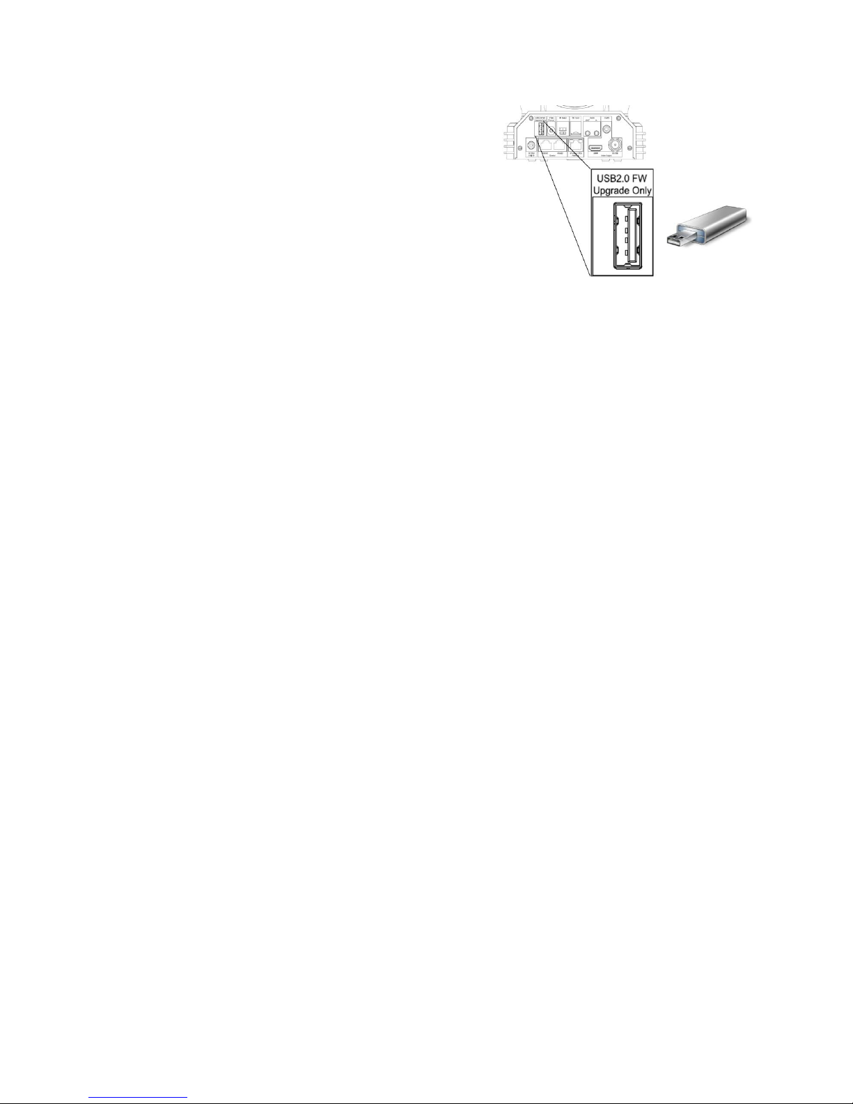
MCU Firmware can be upgraded by following these steps:
1. Load the .bin file onto a flash drive (Formatted as FAT32),
and name the file “HD20.bin”
2. With the camera powered off, insert the flash drive to the
USB port on the back panel of the camera
3. Apply power to the camera
The green indicator light above the lens will turn red for a few
seconds while the upgrade takes place. Once the upgrade is finished,
the light will turn green, and the camera will proceed through a
normal boot cycle. Check the data on the OSD boot screen
NOTE:
The firmware upgrade process is intended to be performed under the supervision of a BOLIN-Authorized repair
technician. For assistance with this, please contact your authorized BOLIN Technology dealer, installer, or integrator.
BOLIN Technology Technical Support can also be reached for assistance with this process
Page 29
29
Operation Using the Infrared Remote Controller
Pan/Tilt and Zoom Operation
Panning and Tilting
1. Press the POWER switch.
The camera will turn on and perform the pan/tilt reset operation
automatically.
2. Press the arrow button to pan or tilt the camera.
While checking the picture on the screen, press the desired arrow
button.
To move the camera in short increments, press the button just for
a moment.
To move the camera in long increments, press and hold the
button.
To move the camera diagonally, press the “←, →” button while
holding down the “↑, ↓” button.
Restore to starting position
Press the HOME button.
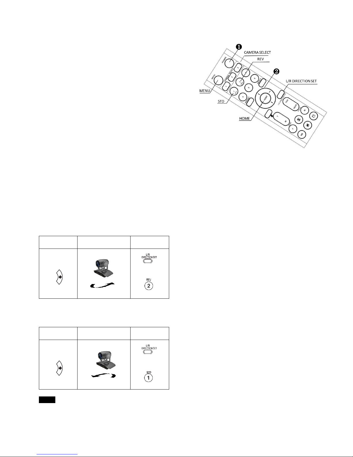
If the camera moves in a different direction from the one that you intended
The camera is preset so that the image output from the camera is rotated toward the right whenever you press
the “←, →” button.
To face the camera toward the opposite direction
You might wish to face the camera toward the opposite direction from that of the button you pressed, for example, when
you change the direction of the camera while checking the picture on the screen. In such a case, press the 2 (REV) button
while holding down the L/R DIRECTION SET button.
Arrow button
Movement of the
camera
Setting
While holding
down
Press
To reset the setting
To reset the setting, press the 1 (STD) button while holding down the L/R DIRECTION SET button.
Arrow button
Movement of the
camera
Setting
While holding
down
Press
Note
The above setting only changes the signal emitted from the infrared remote controller, and does not change the setting of
the camera itself. Therefore, repeat the setting for each infrared remote controller if you are using more than one infrared
remote controller.
Page 30

30
When the STANDBY lamp is blinking
If the camera is moved forcibly, or a finger or other object interferes with camera movement, the camera may fail to
memorize the pan/tilt position.
Press the PAN-TILT RESET button to reset the pan/tilt position.
Zooming
Button [T] - Zoom-IN and [W] - Zoom-OUT.
Button [F] – FAST mode.
Press once and the LED turns red to activate the Fast Zoom Speed Mode,
press again to go back to normal Zoom Speed mode.
Operating Multiple Cameras with the Infrared Remote Controller
1. Set the DIP Switch on the bottom of the camera to the number of camera you want to operate to 1, 2 or 3.
(See bottom DIP Switch setting instruction)
2. Press the CAMERA SELECT button on the infrared remote controller that
corresponds to the number set in step
Then, you can operate the camera(s) specified by number. Every time you operate the camera(s) using the infrared remote
controller, the CAMERA SELECT button pressed in step 2 lights.
Adjusting the Camera
Focusing on a Subject
Focusing the camera on a subject automatically
Press the AUTO button.
The camera focuses on the subject at the center of the screen
automatically.
Focusing the camera on a subject manually
After pressing the MANUAL button, press either the FAR or the NEAR
button to have the camera focus on the subject.
Shooting with Back Lighting
When you shoot a subject with a light source behind it, the subject becomes dark. In such a case, press the BACK LIGHT
button.
To cancel the function, press the BACK LIGHT button again.
Note
The BACK LIGHT function is effective if MODE is set to FULL AUTO in the EXPOSURE menu of the camera.
Page 31
31
Storing the Camera Settings in Memory — the Presetting Feature
Memory (Preset)
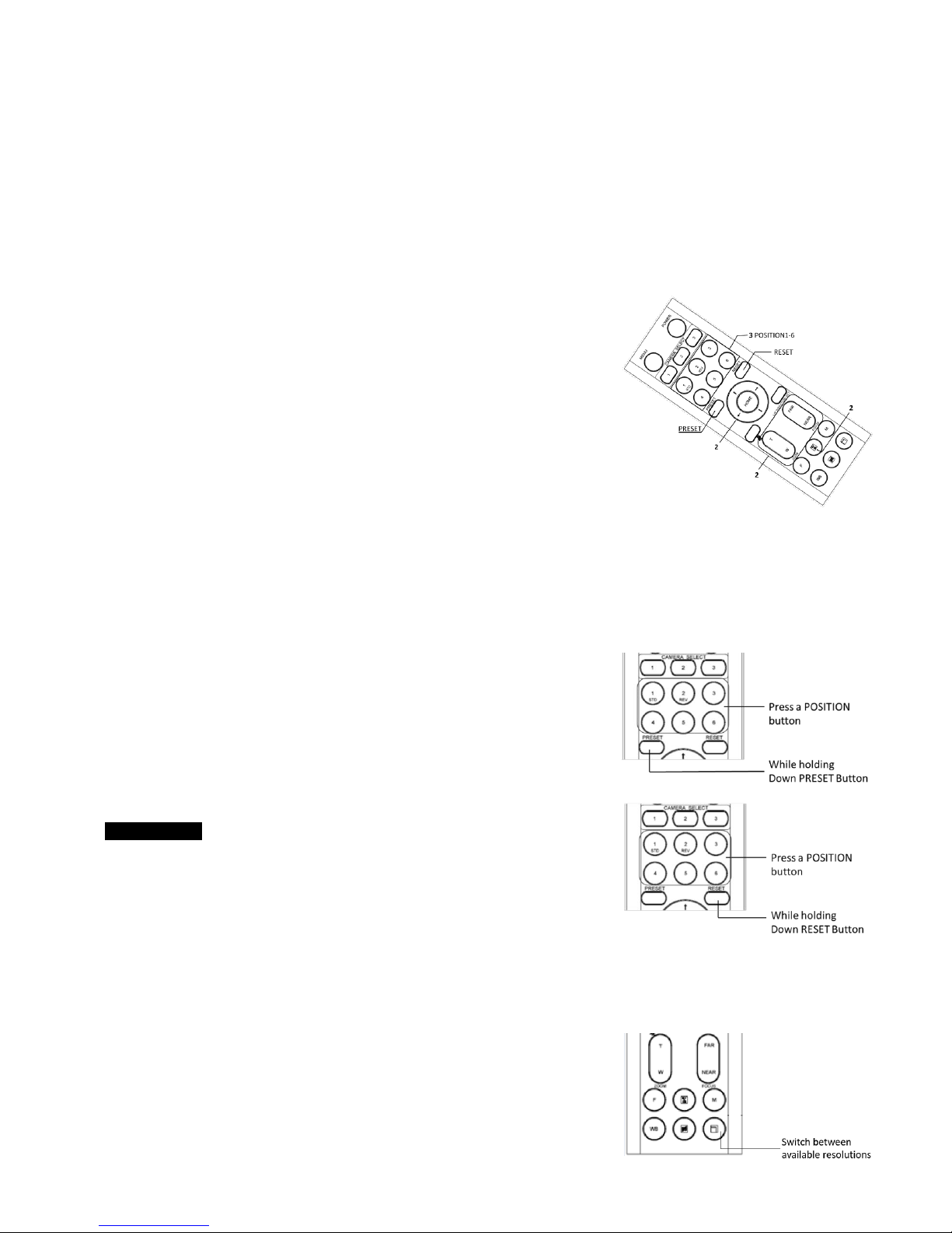
Using the preset function, 6 sets of camera shooting conditions can be stored and recalled. 6 sets of camera shooting
conditions can be stored and recalled by using remote controller. Up to 128 presets via protocol programming.
This function allows you to achieve the desired status instantly, even without adjusting the following items each time.
Pan/Tilt Position
Zoom Position
Focus Auto/Manual
Focus Position
AE Mode
Shutter control parameters
Bright Control
Iris control parameters
Gain control parameters
Exposure Compensation On/Off
Exposure Level
Backlight Compensation On/Off
White Balance Mode
R/B Gain
Aperture Control
WD Parameter
The settings stored using this function are recalled when the power is turned on.
1. Press the PAN-TILT RESET button to reset the pan/ tilt position.
2. Adjust the position, zooming, focusing and backlighting of the camera.
While holding down the PRESET button, press any of the POSITION buttons, 1 to 6, in which you want to store the
settings.
Recalling the stored settings
Press any of the POSITION buttons, 1] to [6], in which you have stored the
settings.
Cancelling the preset memory
While holding down the RESET button, press the POSITION button from
which you want to cancel the settings.
Notes
When the power is turned on, the camera starts with the settings
stored in POSITION 1.
If you want to retain the previous pan and tilt positions, etc. before
the power is turned off and turned on again, store those positions
in POSITION 1.
When you are storing or cancelling the settings in one POSITION,
you cannot call up, store or cancel the settings in another POSITION.
When the menu is displayed on the screen, you cannot perform the operation for storing, recalling, or
cancelling the setting. Be sure to return to the normal display before starting these operations.
Changing Resolutions
Press the Video Format Switching button to populate a menu
where you can switch resolutions
Use the arrow keys to navigate
Press Home to select
Screen will show ‘CHANGING…”
Press Menu to exit
Page 32
32
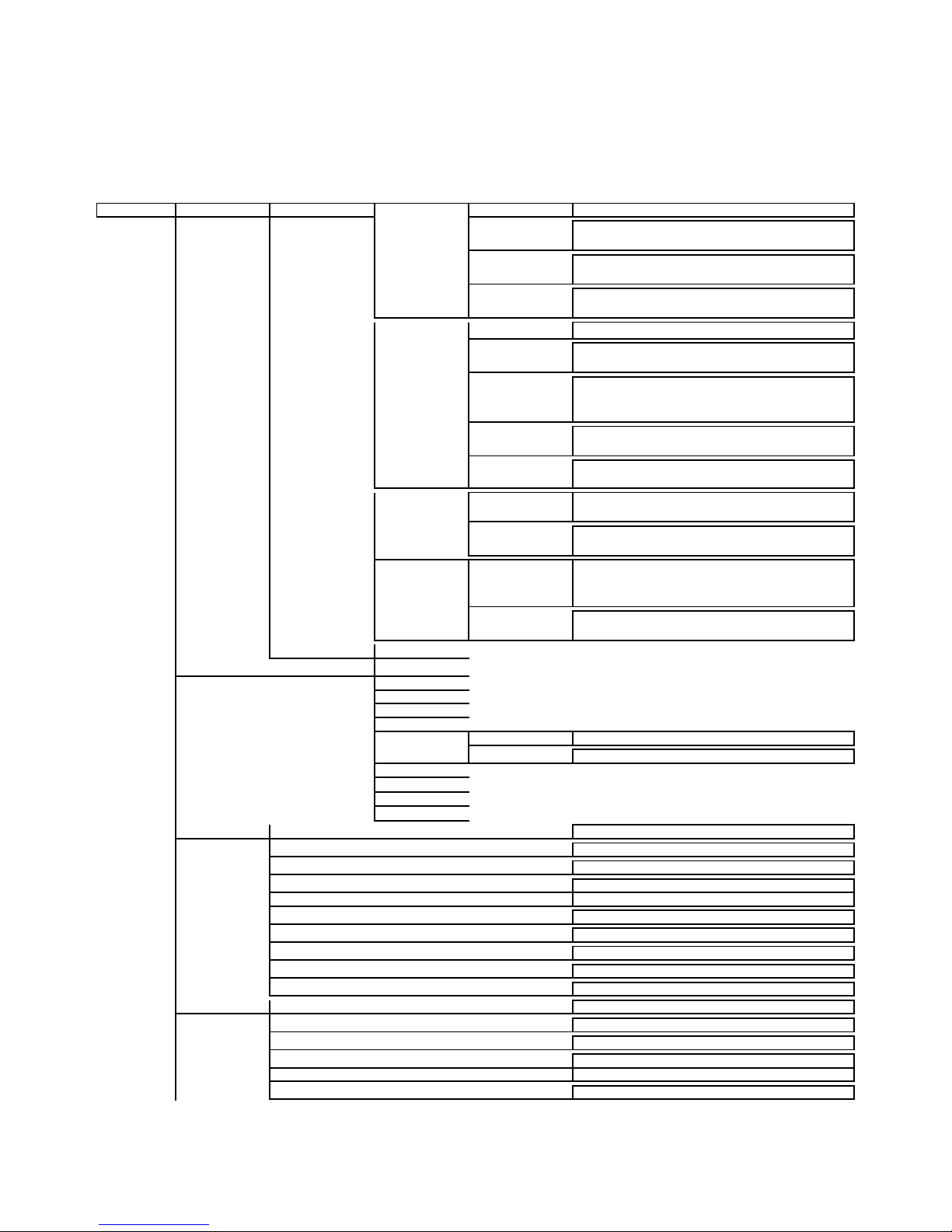
Menu Configuration
The menus of the camera are configured as described below. The initial settings of each item are in
bold.
SDI Menu Configuration
Menu EXPOSURE MODE FULL AUTO SLOW SHUTTER ON, OFF
S. SHUTTER LIMIT 1/1, 1/2, 1/4, 1/8, 1/15, 1/30
AE RESPONSE 1 - 48
GAIN LIMIT
10.7dB, 14.3dB, 17.8dB, 21.4dB, 25dB, 28.6dB, 32.1dB, 35.7dB,
39.3dB, 42.8dB, 46.4dB, 50dB
MANUAL GAIN 0, 2, 4, 6, 8, 10, 12, 14, 16, 18, 20, 22, 24, 26, 28 Db
GAIN LIMIT
10.7dB, 14.3dB, 17.8dB, 21.4dB, 25dB, 28.6dB, 32.1dB, 35.7dB,
39.3dB, 42.8dB, 46.4dB, 50dB
SPEED
1/1, 1/2,1/4, 1/8, 1/15, 1/30, 1/60, 1/90, 1/100, 1/125, 1/180,
1/250, 1/350, 1/500, 1/725, 1/1000, 1/1500, 1/2000, 1/3000,
1/4000, 1/6000, 1/10K sec
IRIS
CLOSE, F14, F11, F9.6, F8.0, F6.8, F5.6, F4.8, F4.0, F3.4, F2.8, F2.4,
F2.0, F1.6
HIGH SENSITIVITY OFF, ON
IRIS
IRIS PRI
IRIS
CLOSE, F14, F11, F9.6, F8.0, F6.8, F5.6, F4.8, F4.0, F3.4, F2.8, F2.4,
F2.0, F1.6
GAIN LIMIT
10.7dB, 14.3dB, 17.8dB, 21.4dB, 25dB, 28.6dB, 32.1dB, 35.7dB,
39.3dB, 42.8dB, 46.4dB, 50dB
SHUTTER PRI
SPEED
1/1, 1/2,1/4, 1/8, 1/15, 1/30, 1/60, 1/90, 1/100, 1/125, 1/180,
1/250, 1/350, 1/500, 1/725, 1/1000, 1/1500, 1/2000, 1/3000,
1/4000, 1/6000, 1/10K sec
GAIN LIMIT
10.7dB, 14.3dB, 17.8dB, 21.4dB, 25dB, 28.6dB, 32.1dB, 35.7dB,
39.3dB, 42.8dB, 46.4dB, 50dB
EX-COMP OFF , ON
WHITE BALANCE MODE AUTO
INDOOR
OUTDOOR
OPW
ATW
USER R GAIN 0-255
B GAIN 0-255
OUTDOOR AUTO
SVL AUTO
SVL
SVL OUTDOOR A.
PICTURE1 SHARPNESS 0-15
EFFECT OFF , B&W
NOISE REDUCTION OFF, 1-5
FLIP OFF, ON
MIRROR OFF, ON
DE-FLICKER OFF, ON
WDR OFF, ON
COLOR 1-15
HUE 1-15
CONTRAST 0-255
PICTURE2 CHROMA SUPRESS OFF, LOW, MID, HIGH
HLC MODE OFF , ON
BACKLIGHT COM. OFF , ON
STABILIZER OFF, ON
STABLE ZOOM OFF, ON
GAMMA 0, 1
Page 33
33
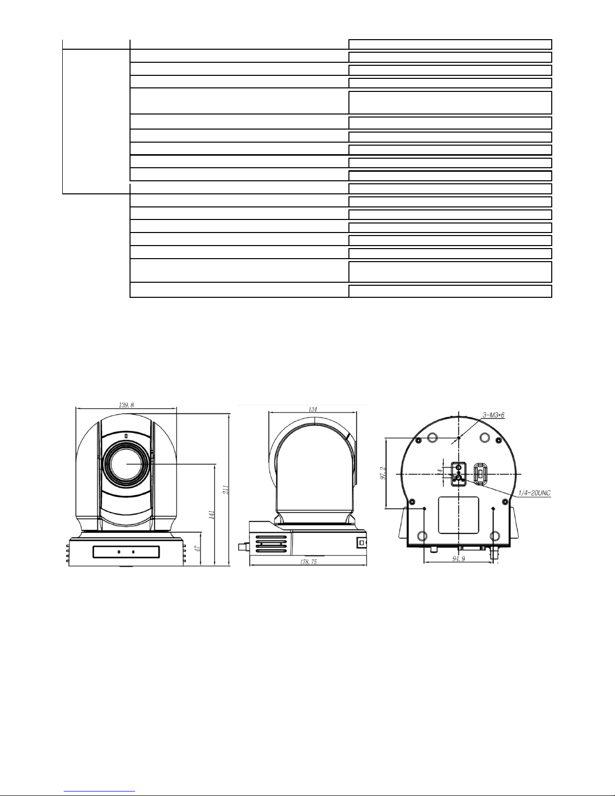
Dimension
Unit: mm
PAN TILT ZOOM DIGITAL ZOOM OFF, ON
ZOOM RATIO OSD OFF, ON
AF SEN. LOW , NORMAL
MF SPEED 0 - 7
NEAR LIMIT
OVER, 1cm, 11cm, 30cm , 80cm, 1.2m, 1.4m, 1.6m, 2.0m, 2.5m,
3.1m, 4.2m, 6m, 10m, 20m
ADAPTIVE PT OFF, ON
P/Z SPEED 0-5
PRESET SPEED 0-5
PAN DIR NORMAL, INVERT
TILT DIR NORMAL, INVERT
SYSTEM PELCO ID 001 -255
IR-RECEIVE OFF, ON
DISPLAY INFO OFF, ON
PRESET MEMORY OFF , ON
FACTORY RESET
RELOAD PRESET 1 OFF, ON
VIDEO FMT
1080p:60/59.94/50/30/29.97/25; 1080i:60/59.94/50;
720p:60/59.94/50/30/25
SV: V0B1100S36040AD04
Page 34

34
www.bolintechnology.com
2082 TECHNOLOGY LLC
dba
BOLIN TECHNOLOGY
 Loading...