

Page 1
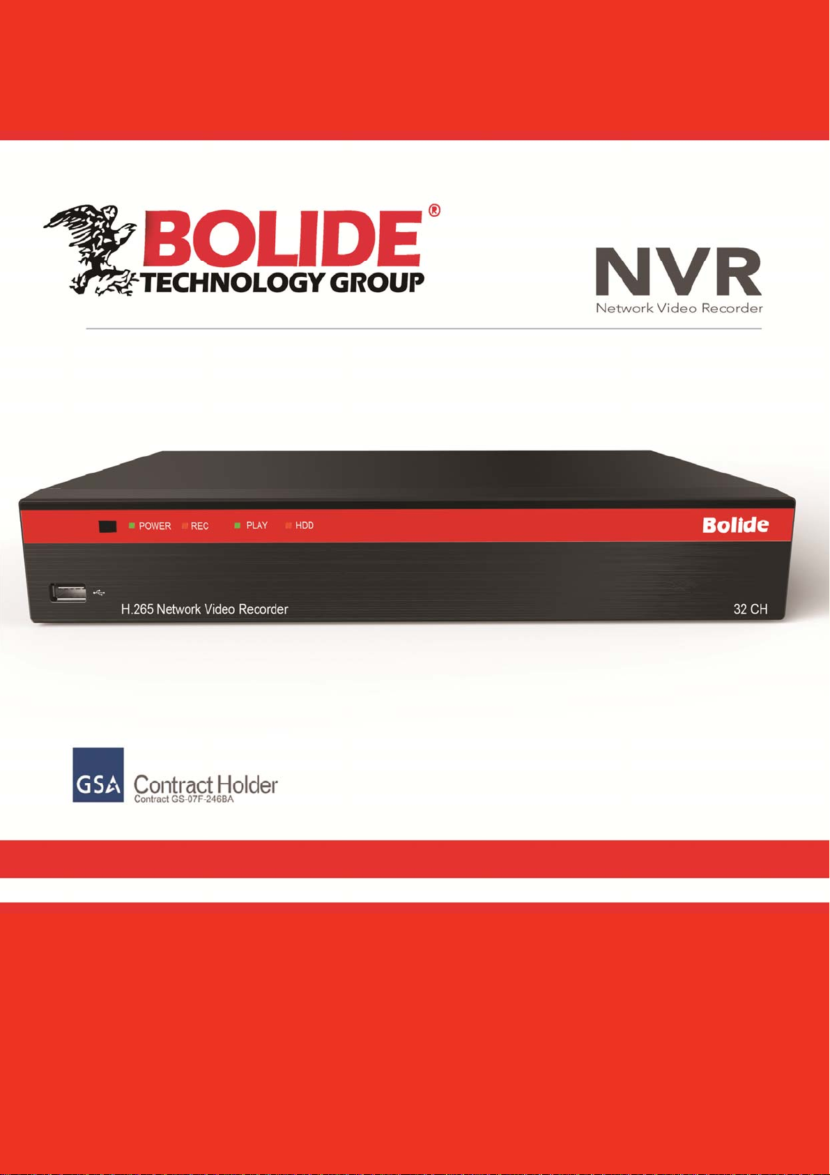
USER MANUAL
1
Page 2

USER MANUAL
2
Page 3

Contents
USER MANUAL
SAFETY INSTRUCTION
CHAPTER 1 OVERVIEW OF NVR
1.1 REAR PANEL
...........................................................................................................
1.2 REMOTE CONTROLLER
CHAPTER 2 NVR CONNECTION
2.1 HDD INSTALLATION
...............................................................................................
..............................................................................
............................................................................................
...............................................................................
.................................................................................................
2.2 IP CAMERA AND MONITOR CONNECTION
2.3 POWER SUPPLY CONNECTION
CHAPTER 3 NVR BOOT UP
3.1 SYSTEM INITIALIZATION
3.2 STARTUP WIZARD
3.3 MAIN INTERFACE
.....................................................................................................
CHAPTER 4 NVR MENU
POPUP MENU
4.2 MAIN MENU
4.2.1 Parameter
.................................................................................................................
...........................................................................................................
.....................................................................................................
4.2.2 Record Search
4.2.3 Device
4.2.4 System
4.2.5 Advanced
4.2.6 Shutdown
ENU LOCK
4.3 M
4.4 SPLIT MODE
4.5 STREAM SWITCH
............................................................................................................
..........................................................................................................
......................................................................................................
......................................................................................................
..........................................................................................................
..........................................................................................................
...................................................................................................
4.6 VIEW IMAGE QUALITY
TA R T SEQUENCE
4.7 S
4.8 M
4.9 S
.....................................................................................................................
UTE
TA R T CRUISE
......................................................................................................
...........................................................................................
....................................................................................................
..............................................................................................
.............................................................................................
...........................................................................................
.................................................................................................
...............................................................................
........................................................................................
...............................................................
3
1
1
2
3
3
3
3
3
3
4
6
7
7
10
11
25
34
36
42
44
44
45
45
45
45
45
45
CHAPTER 5 WEB APPLICATION MANAGER
5.1 ACTIVEX CONTROL DOWNLOAD AND INSTALLATION
5.2 WEB APPLICATION MANAGER LOGIN
5.3 LIVE INTERFACE
5.3.1Menu Bar
5.3.2 Playback
5.3.3 Parameter Setting
5.3.4 Local Setting
5.3.5 Logout
....................................................................................................
........................................................................................................
........................................................................................................
........................................................................................
.................................................................................................
............................................................................................................
...................................................................
1
......................................................
.............................................
47
47
48
49
49
51
54
65
65
Page 4

USER MANUAL
CHAPTER 6 APPENDIX
6.1 TROUBLESHOOTING
6.2 USAGE MAINTENANCE
6.3 SYSTEM CONNECTION DIAGRAM
.............................................................................................
..............................................................................................
..........................................................................................
..........................................................................
6.4 ACCESSORIES (GOODS IN KIND PREVAIL)
............................................................
66
66
67
68
68
2
Page 5

USER MANUAL
SAFETY INSTRUCTION
Please carefully read the following safety instruction so as to avoid personal
injuries and prevent the equipment and other connection devices from being
damaged.
1. Power sources (note: please use the power supply attached or specified
by the manufacturer)
Never operate the equipment by unspecified power supply.
2. Never push objects of any kind through openings of NVR;
Never push objects of any kind through openings of NVR so as to avoid electric shock or
other accidents.
3. Do not put the equipment in the dusty field;
Do not put the equipment in the dusty field.
4. Do not place the equipment under rain or humid environment
Do not place the equipment under humid environment like basement. If the equipment is
in contact with water, please unplug the power cable and immediately contact your local
dealer.
5. Keep the surface of the equipment clean and dry
Use soft damp cloth to clean the outer case of NVR (do not use liquid aerosol cleaners)
6. Do not operate if any problems are found
If there are any strange smell or sound, unplug the power cable and contact the
authorized dealer or service center.
7. Do not try to remove the upper cover
Warning: Do not remov e the cap of NVR so as to avoid electric shock.
8. Handle with care
If NVR does not work normally because of hitting on the hard object, please contact the
authorized dealer for repair or replacement.
9. Use standard lithium battery(Note: Use the batteries attached or specified by the
manufacturer)
After cutting off the power supply, if the system clock cannot continue to work, please
replace the standard 3V lithium battery on the main board.
Warning: Turn off NVR before replacing the batteries, or you may be suffered from
serious electric shock. Please properly dispose of the used batteries.
10. Put the equipment in a place with good ventilation.
The NVR system includes HDD, which produces large amount of heat during operation.
As a result, do not block the ventilation openings(on the top, bottom, both sides and the
reverse side) for cooling the system during operation. Install or put the equipment in the
place with good ventilation.
11. The attached power adapter can only be used for 1 set of NVR. Do not connect
more equipment, or NVR may be restarted repeatedly because of insufficient
power.
12. Prevent the equipment from water dropping or splashing. Do not place objects
containing water, such as flower vase, on the equipment.
3
Page 6
Chapter 1 Overview of NVR
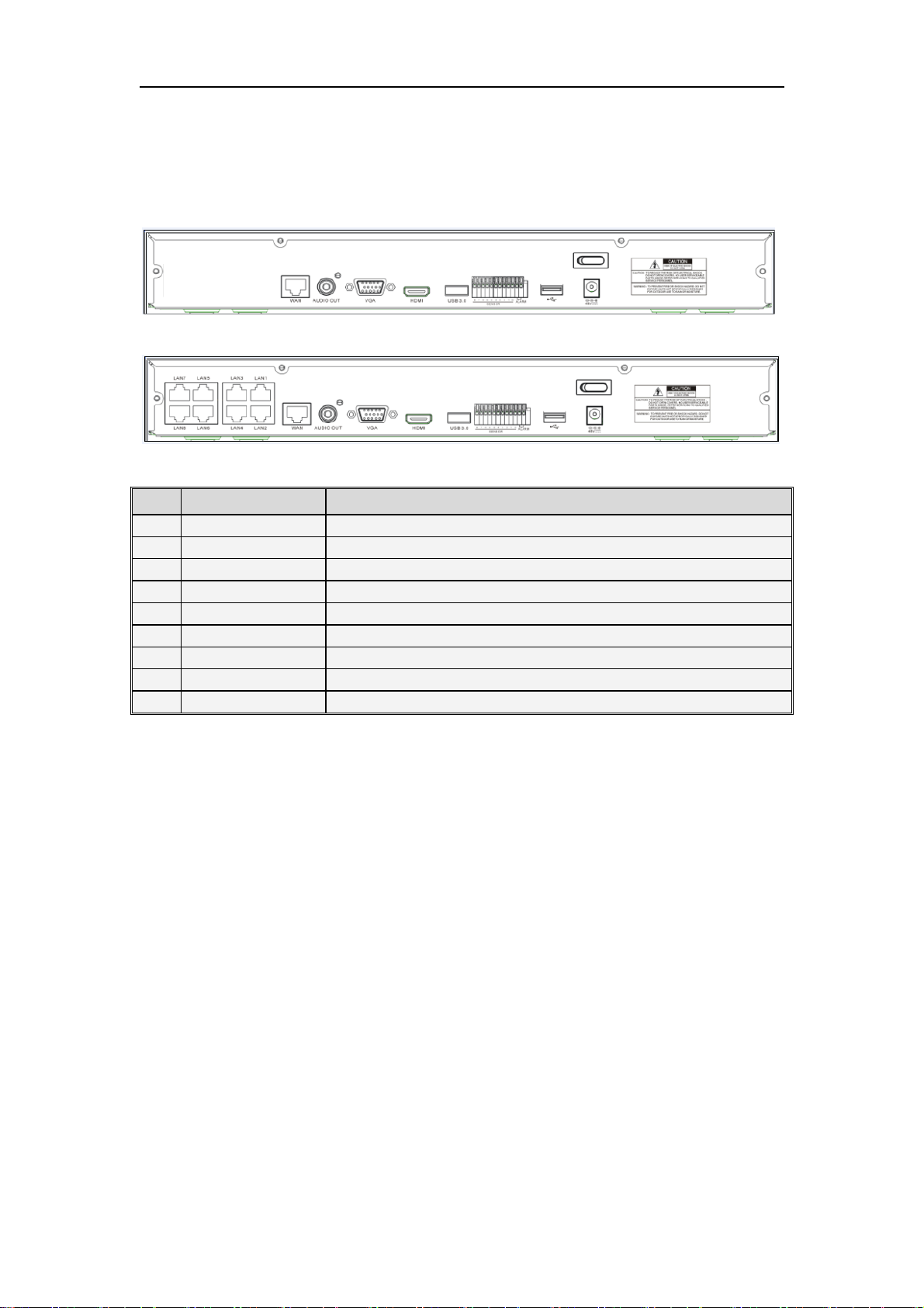
1.1 Rear Panel
NVR Rear Panel(For reference only)
Item Physical Port Connection Method
1 PowerPort
2 PowerSwitch
3 USB Port
4 Sensor/Alarm
5 HDMI Port
6 VGA Port
7 AUDIO OUTPUT
8 WAN Port
9 LAN Port
Startup and shutdown
Connect the attached power supply
Connect USB devices, such as USB mouse and USB flash disk.
Connect to sensor or alarming device
HDMI high definition port
Connect to VGA monitor, such as PC monitor
Audio signal output, R CA interface
Network input interface of the router/Connect to IP camera.
LAN network interface, support POE, can supply power to the camera.
Tabl e 1 -2
1
Page 7
Remote Controller
1.2
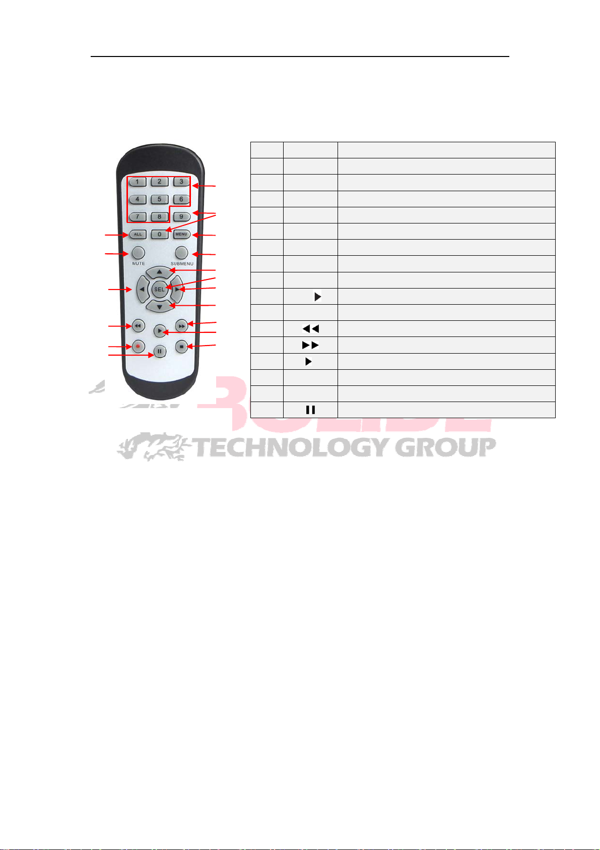
Remote Controller (For reference only)
Table 2-3 Key functions of the remote controller
Item Key title Key function
1 1-8 Channel select 1-8; Numeric key
1
2
3 ALL Multiple display mode
2
3
5
9
4
6
7
8
9
4 Menu Enter into Main menu/Exit
5 Mute Mute On/off
6
Submenu
7 ▲ Up arrow key, volume increase
8 SEL Select key/Edit key
9
11
14
16
10
12
13
15
10 ▼ Down arrow key, Volume decrease
11 Rewind key
12 Forward key
13 Enter into record search menu / Play key
14 ● Record key
15 ■ Stop manual record; stop playing
16 Pause/Sequence key
Table 1- 3
9、0
◄/
Numeric key
Go to submenu
Left/Right key; Decrease/increase parameter value of control bar.
2
Page 8

Chapter 2 NVR Connection
2.1 HDD Installation
Caution: Please do not take out hard drive when NVR is running!
HDD Installation:
(1) Cut power firstly, and then remove screws on both sides and rear panel and open NVR
upper cover.
(2) Connect HDD data cable and power cable to the main board. Install the HDD and fix it
on the bracket and then connect the HDD power cable and data cable.
(3) Put the upper cover back carefully
Note: If user requires higher performance HDD, it is strongly recommended to use hard
drive for security.
2.2 IP Camera and Monitor Connection
Transmit signals of IP camera to NVR by the network cable and connect VGA port
and HDMI port for output (Refer to Chapter 2.2 Rear Panel). Refer to Chapter 7 System
Connection Diagram.
2.3 Power Supply Connection
Please use attached power adapt er to connect NVR. Before power on, make sure
network port is well connected.
Chapter 3 NVR Boot up
3.1 System Initialization
After connecting the power cable of NVR to wall outlet and pressing the power button, you
will enter into the NVR system initializing screen.
Note:The illustration in the user
manual may not be the same as the
menu interface in your monitor. All
the illustrations are for users’
reference.
3
Page 9
3.2 Startup Wizard
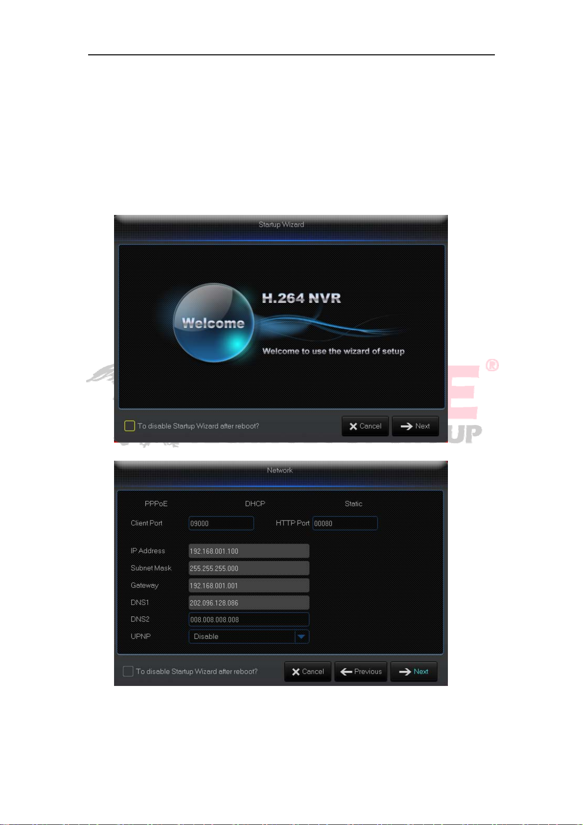
After NVR startup is completed, the startup wizard will be displayed. If you do not
want to make any setting, you may click “To disable Startup Wizard after reboot?” to
cancel.
Wizard setting menu includes : Homepage, Network setup, IPC setup, Record
Schedule and hard disk maintenance..
1.Homepage and network setup. In network setup page, user may set the network of
NVR.
4
Page 10
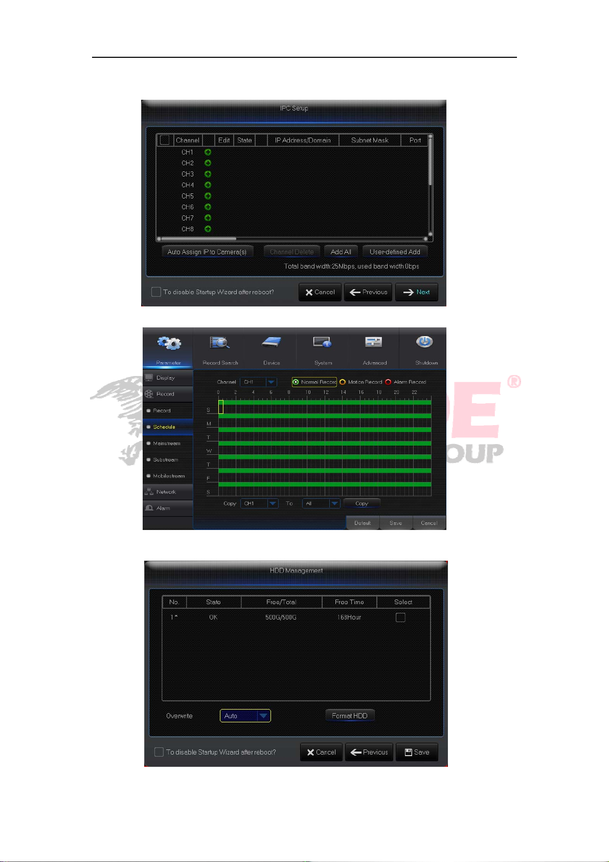
2. In this page, user may add and delete IPC. In this page, user may set recording time
and scheduled recording of NVR.
3. It supports HDD formatting and overwriting type.
5
Page 11
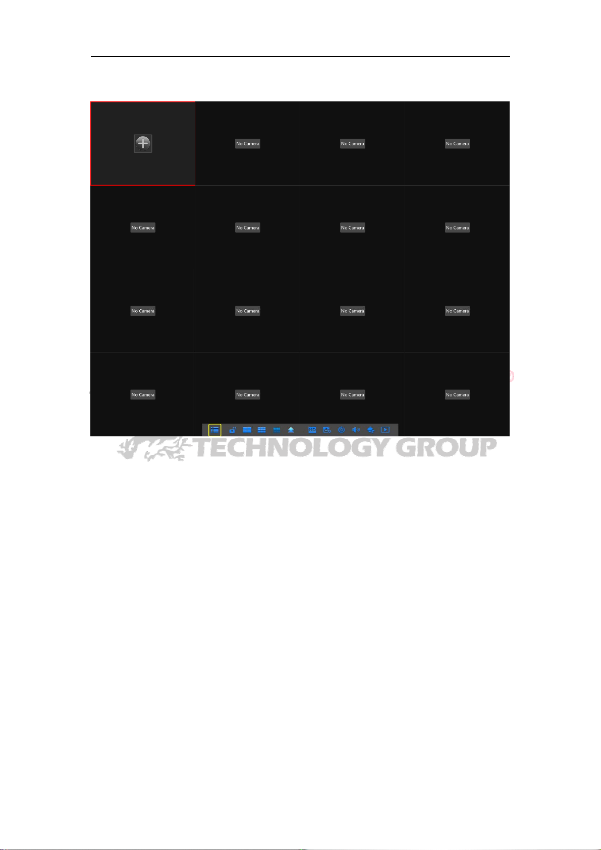
3.3 Main Interface
Note: When internal HDD is not connected to NVR or the HDD is not formatted, first
channel of the live screen and accompany buzzer alarm. If you want to close the buzzer
alarm, please enter into [Event Alarm] to set HDD loss, HDD space not enough and
alarm output to “off”.
6
Page 12

Chapter 4 NVR Menu
Popup Menu
After finishing system initialization, click right key of mouse on preview interface
or slide the mouse to the bottom of screen to enter into Pop-up Menu. Now you could
perform parameter setting and operate on Main Menu, Multi-Pics, Auto Cruise, Record
Search, Sequence, Volume setting and Stream switching, shown as Picture 4-1.
The options in the pop-up menu may be varied slightly according to different parameter
settings
The options in the menu will be explained in detail in the following chapters.
.
7
Page 13
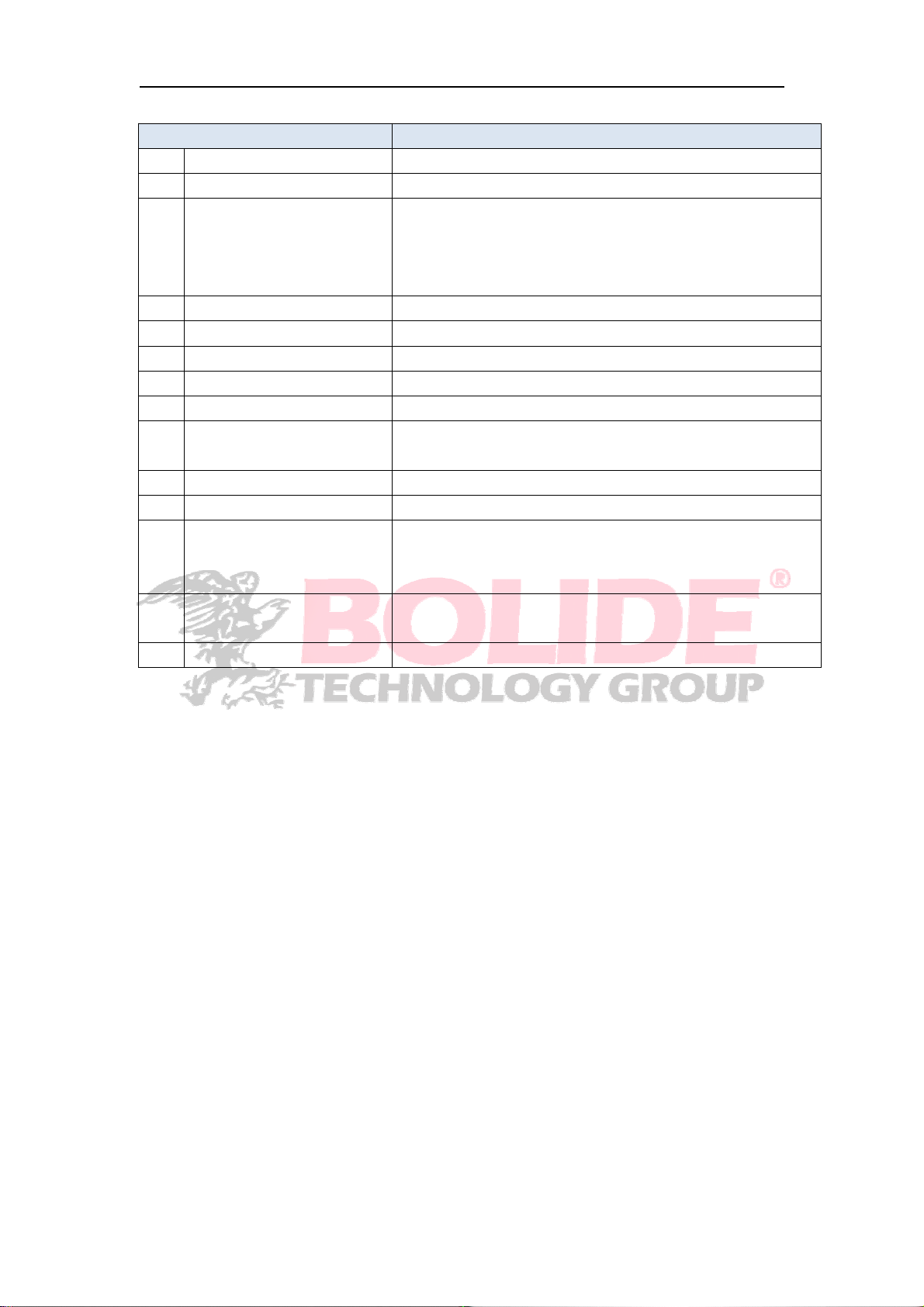
Component Name Function
1 Main Menu Access the main menu
2 Manually Lock Screen Sign out or access sign-in page
Four-Channel
3-5
6 More Layout Displays different channel layout
7 Stream Switch Switch between Main Stream and Sub Stream
8 View Image Quality Switch among Realtime, Balanced and Smooth
9 SEQ Start or stop SEQ
10 Mute Audio output and volume control
11 PTZ Cruise
12 Playback Replay video recorded
13 Record Enable or disable manual recording
14 Instant Playback
15 Zoom
16 Color Adjust the color of video
Layout/Nine-Channel
Layout/Sixteen-Channel
Layout
Display four channels of video/ Display nine channels
of video/ Display sixteen channels of video
Set the preset positions for PTZ, the dome camera will
start to cruise.
Display channel name Quick playback of video of last
5
minutes
Hold and drag mouse cursor to select a frame of
current video to zoom in
8
Page 14
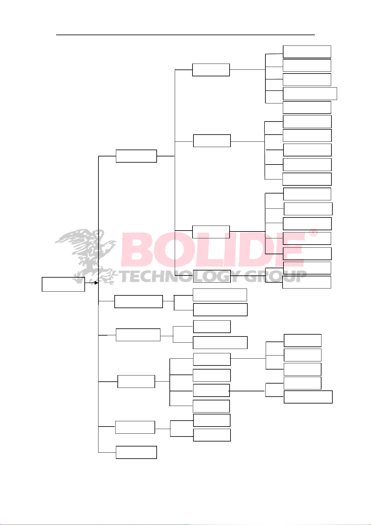
4.1 Main Menu Guide
IP Camera
Parameter
Display
Record
Network
Live
Output
Image Control
Privacy Zone
Record
Schedule
Mainstream
Substream
Mobliestrea
Network
Switch
Email
DDNS
Main Menu
Record Search
Device
System
Advanced
Alarm
Record Search
Event Search
HDD
Cloud Storage
General
Users
Info
Log
Maintain
Events
RTSP
Motion
Alarm
General
DST
NTP
Info
Channel Info
Shutdown
9
Page 15
4.2 Main Menu
On LIVE mode, click the mouse button, or [Menu] button on the remote controller, or
click [
System, Advanced and Shutdown.
] icon on the toolbar to enter the main menu screen.
If system interface is locked, refer to chapter 4.3 to unlock by inputting password.
In Main Menu mode, you can make settings for Parameter, Record Search, Device,
10
Page 16
4.2.1 Parameter
4.2.1.1 Display
4.2.1.1.1 IP Camera
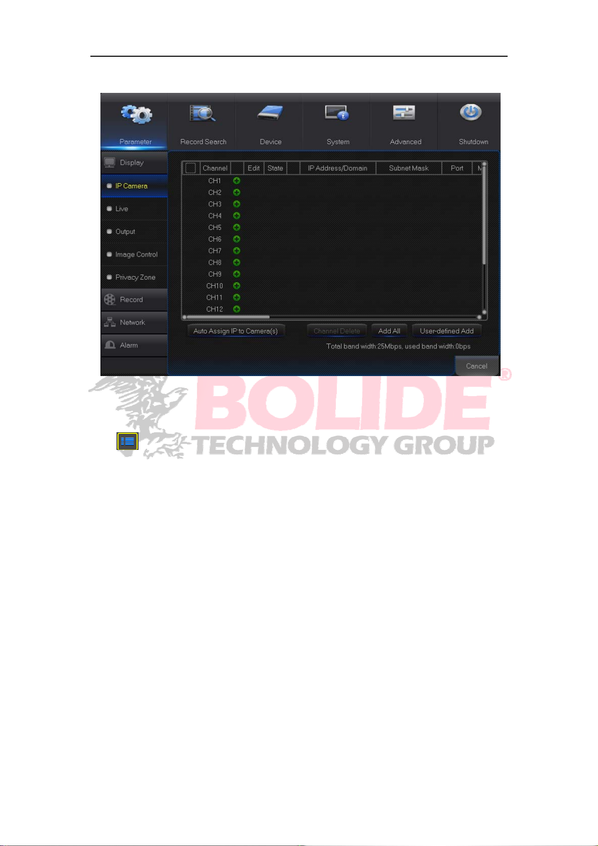
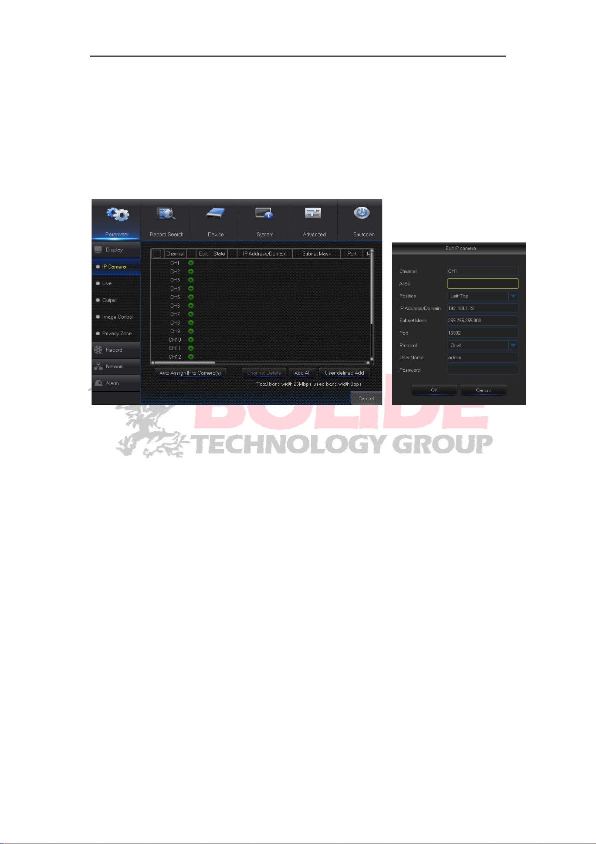
Go to “Main Menu”→“Display”→“IP Camera” to enter into the interface.
Channel:IP camera channel
Edit:Modify the name and location of channels, change other IPC or protocols, etc.
State:Display IPC on-line state
IP address:Modify IP address of IP camera.
IP Address/Domain:IP address of the IPC connected of the channel
Subnet Mask:IP camera subnet mask
Port:Connection port number of the currently set IPC.
Manufacturer:Manufacturer for different IPC
Device type:Add IPC with different protocols.
Protocol: The selected access protocol for IPC to connect to NVR
MAC Address:Physical address for device
Software:Display current version of IPC.
11
Page 17
4.2.1.1.2 Live
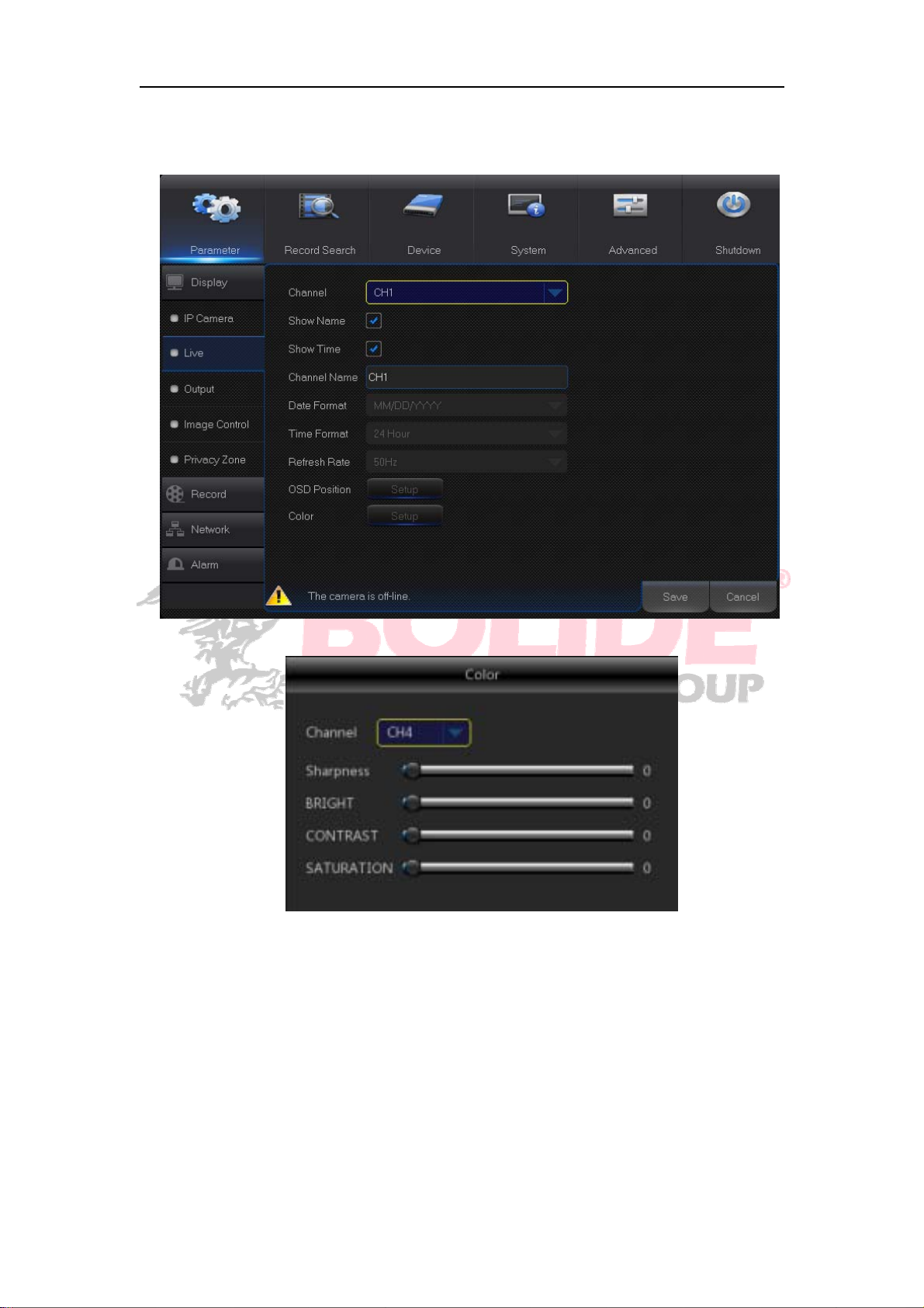
Go to “Main Menu”→“Display”→“Live” to enter into the interface.
Channel:Select channel number.
Show Time:Tick the checkbox to display time.
Channel Name:Name marked on IPC
Date Format:Set date format such as m/d/y or y/m/d
Time Format:12 hour or 24 hour
OSD Position:Freely set the position of IPC name and time
Color : Adjust the chroma, brightness, contrast and saturation of the IPC of the
channel.
12
Page 18
4.2.1.1.3 Output
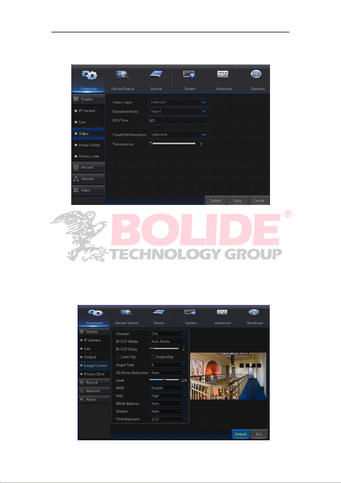
Go to “Main Menu”→“Display”→“Output” to enter into the interface.
Video Output:Live Output
Seq Mode:Set sequence mode
SEQ Dwell Time:Sequence dwell time is set 5 seconds by default. User may set it as
required.
VGA/HDMI Resolution : VGA output or HDMI output. Including 1024×768 ,
1280×1024,1440×900,1280×720,1920×1080
Transparency:Set the transparency of the menu in the range of 0—128.
4.2.1.1.4 Image Control
“Main Menu” →”Display” → “Image Control”, entering the interface.
13
Page 19
Configure the parameters for the IPC, IR-Cut Mode, Angle Flip, Back Light compensation,
3D Noise Reduction , Wide Dynamic, and White Balance. The parmeters take effect
immediately.
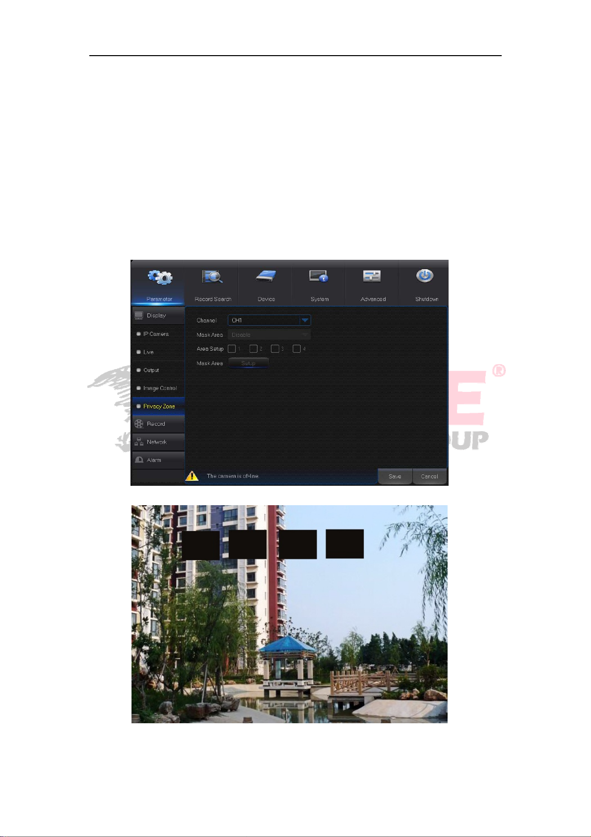
4.2.1.1.5 Privacy Zone
Privacy Zone is for setting some invisible parts in the selected channel.
1.Select the number of the zone to be set (maximum 4 zones can be set for single
channel)
2. Click “Setup” to adjust t he position of the zone.
3. After finish setting, right click the mouse to return to the “Privacy Zone” page.
4. Click “Save” to save the setting.
14
Page 20
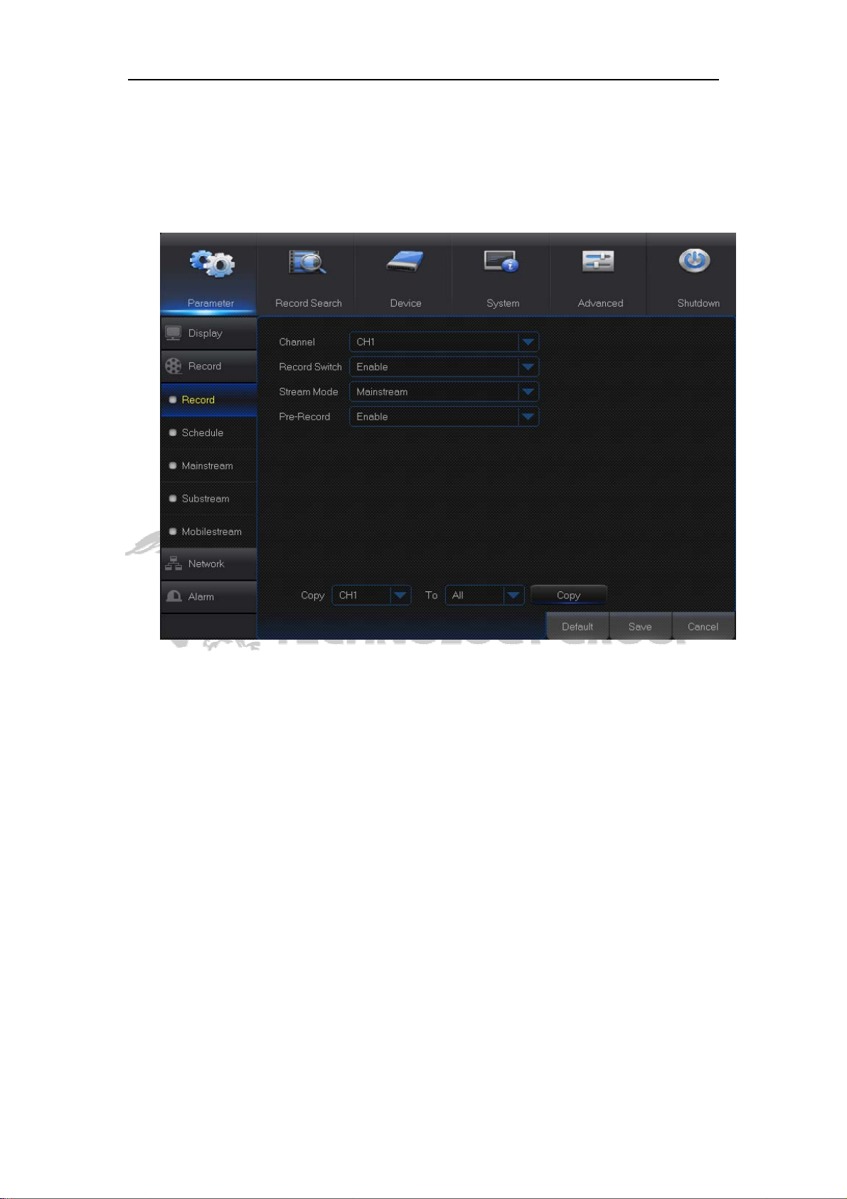
4.2.1.2 Record
4.2.1.2.1 Record
Go to “Main Menu”→“Record”→“Record” to enter into the interface.
Channel:Set the desired channel in the drop-down menu
Record:Set up the record status(Enable/Disable) of each channel.
Stream Mode:Select Mainstream or Substream.
PreRecord: “Enable” status supports pre-record for motion detection record or I/O
trigger record.
15
Page 21
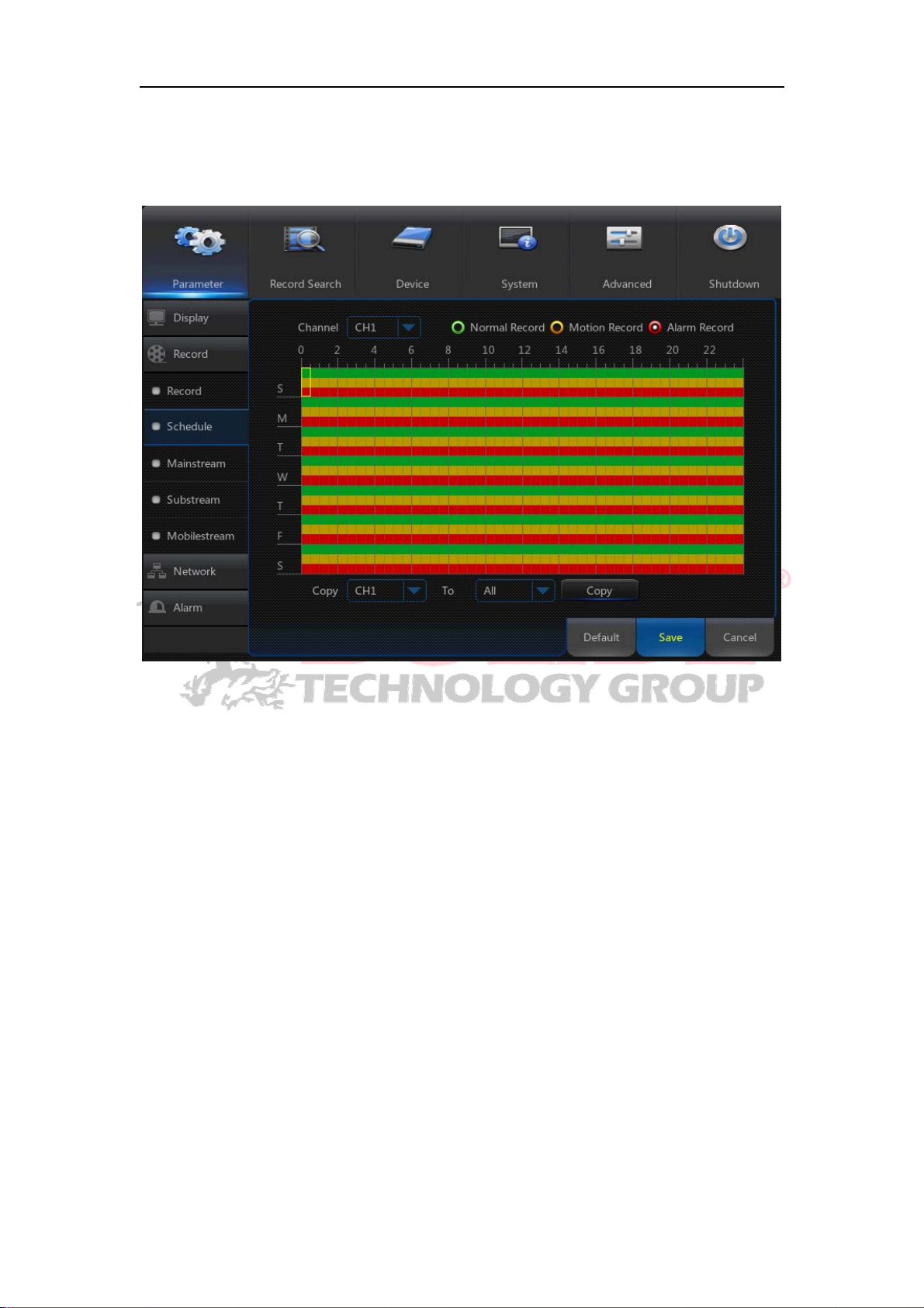
4.2.1.2.2 Schedule
Go to “Main Menu”→“Record”→“Schedule” to enter into the Schedule interface and set the
record schedule of NVR.
Select the channel and the date to be set. One week’s schedule can be set.
The record schedule of the current channel can be copied to any other channel or all
channels.
Note:
1.In the Record menu and Record Search menu, No Color stands for no record;
2.“Green” stands for normal record and “yellow” stands f or motion record
3. “Red” stands for alarm record.
16
Page 22
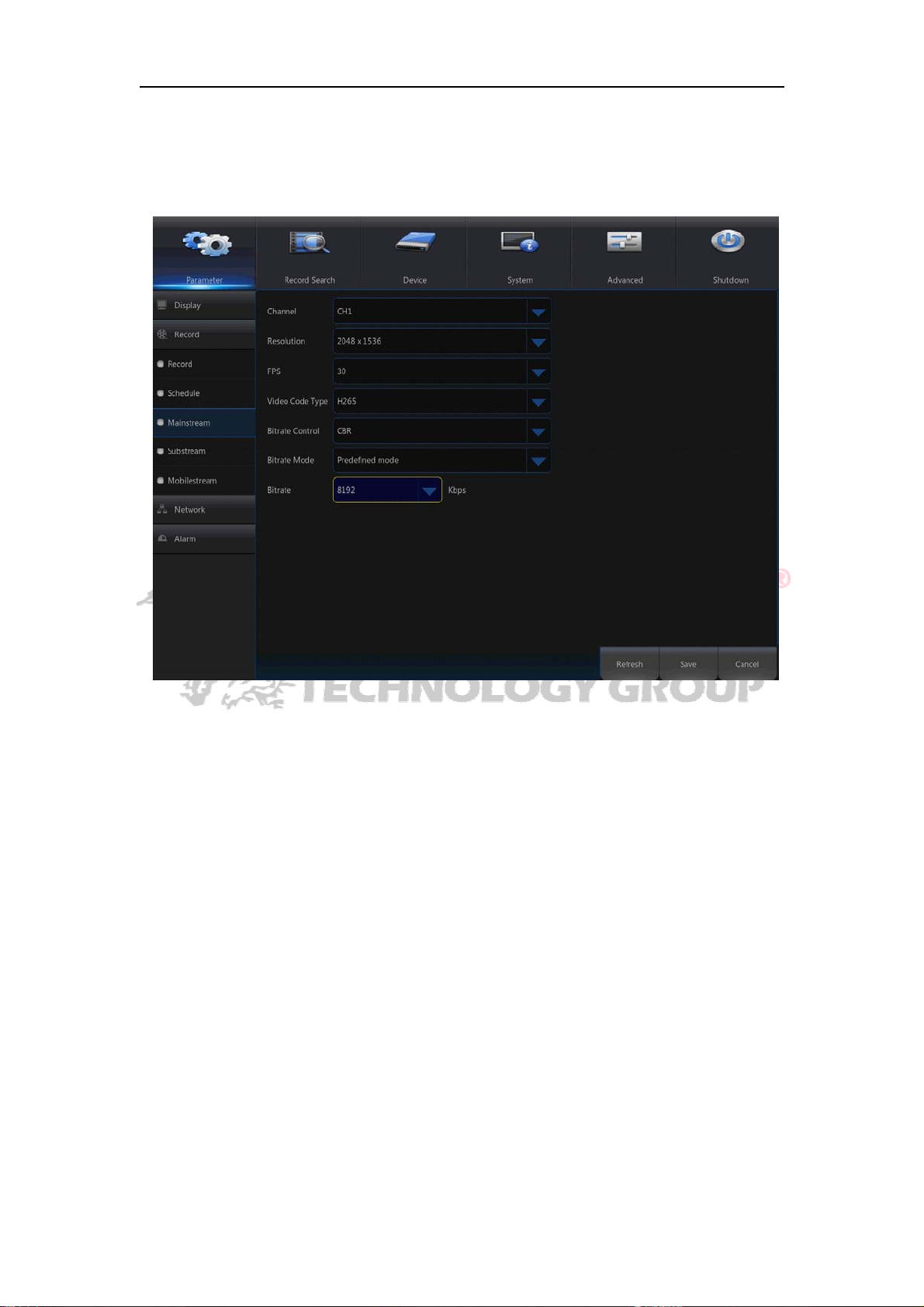
4.2.1.2.3 Mainstream/Substream/Mobilestream
Go to “Main Menu”→“Record”→“Mainstream/Substream/Mobilestream” to enter into the
menu interface.
Picture 4-12
Mainstream ,Substream and Mobilestream are the three video stream of IPC. Mainstream
is mostly used for recording and the substream and Mobilestream are mostly used for
remote network monitoring.
Channel:Select a channel
Resolution:Set IPC resolution as required
FPS:Min 1 and max 30
code type:H.264 and H.265
Bite rate control: Dynamic and Statics
Bitrate Mode:Preview Mode and User-defined Mode
Bitrate:Set IPC bitrate
17
Page 23
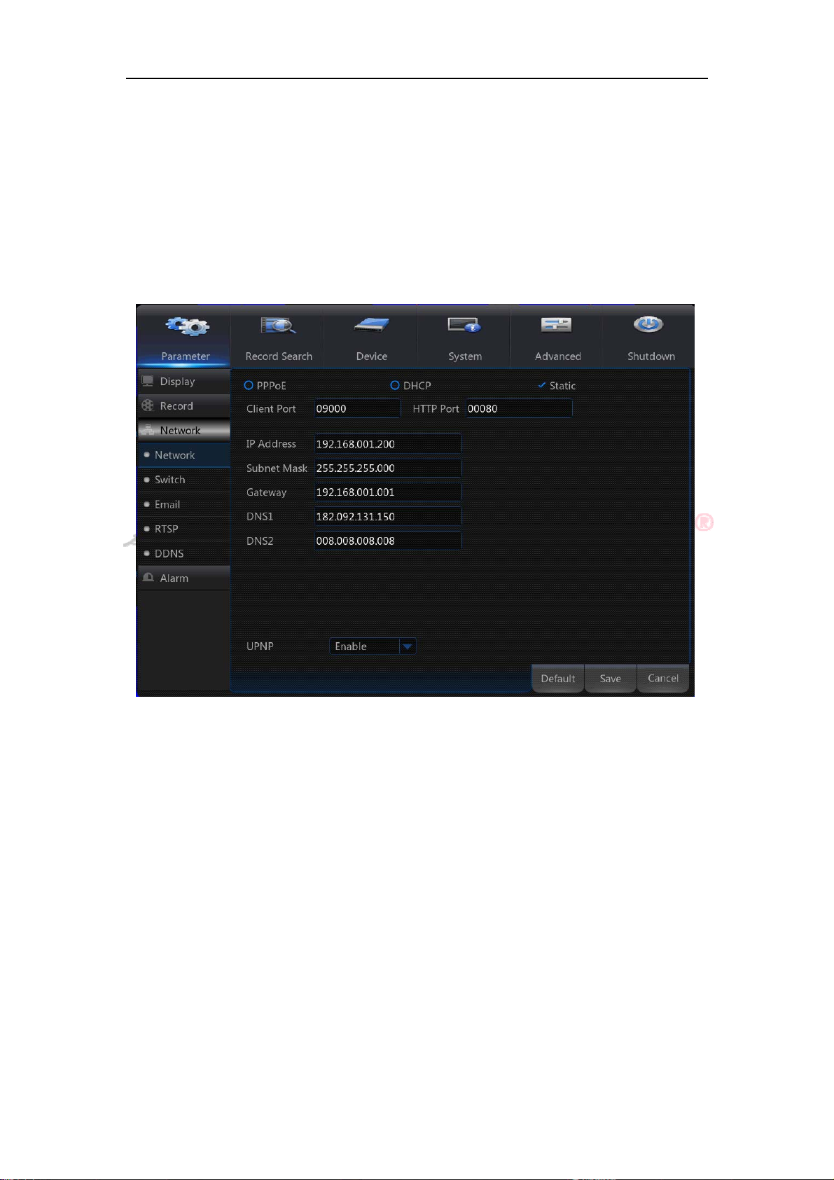
4.2.1.3 Network
4.2.1.3.1 Network
Go to “Main Menu”→“Parameter”→“Network” to enter into the interface.
Select a kind of network connection (PPPOE, DHCP,Static) and set Port, then user may
remotely control the monitoring, recording, playback or backup of NVR through network.
Take DHCP as an example. In this mode, the router automatically assigns IP address
for NVR. After restarting NVR or DHCP server, the IP address obtained by NVR may be
different. As a result, user shall check IP address and port number for each remote access
of NVR. The operation procedure is as follows:
1. Select DHCP, click Save and refresh NVR. Input Client Port and HTTP Port (the two
values must not be the same).
2. Set obtained IP address of NVR and the mapping port. Refer to section4.2.4.2.
3. Remotely visit NVR by IP address:
http://Public network IP: Web port number(such as 00080)
http:// Intranet IP: Web port number(such as 00080)(Only available in the same LAN)
For PPPoe, Static and DHCP, after setting IP address of NVR, the extranet port
shall be mapped on the router before visiting NVR through public network.
Note: Save after setting to make effective. If there are multiple NVR in a LAN, make
sure their MAC addresses are different (Refer to System).
18
Page 24
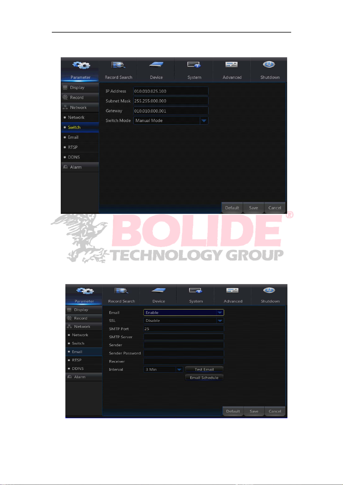
4.2.1.3.2 Switch
Go to “Main Menu”→“Parameter”→“Network”→“Switch” to enter into the menu interface.
4.2.1.3.3 E-mail
Go to “Main Menu”→“Parameter”→“Network”→“Email” to enter into the menu interface.
Receive or Send NVR alarm Email and set parameters like Email address, SSL, Email
Enable, Interval and Email Schedule. The related parameter setting should be consistent
with the NVR local setting.
19
Page 25
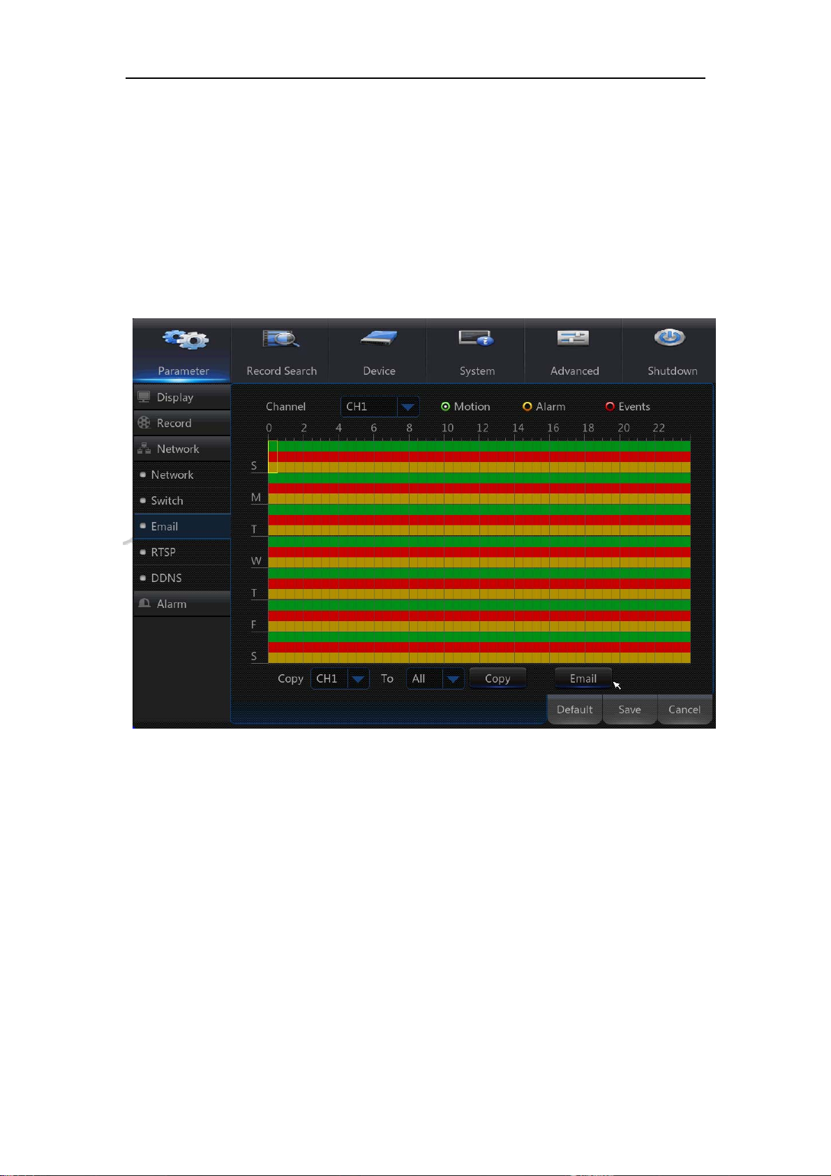
Mail Schedule:
Select the channel and the date you want to set. One week’s schedule can be set.
The record schedule of the current channel can be copied to any other channel or all
channels.
Note:
1. Green stands for Motion: Email will be sent in case of object motion;
2. Yellow stands for Alarm: Email will be sent in case of object alarm;
3. Red stands for Exception: Email will be sent in case of exception, e.g. DiskFull,
DiskError, VideoLoss.
20
Page 26
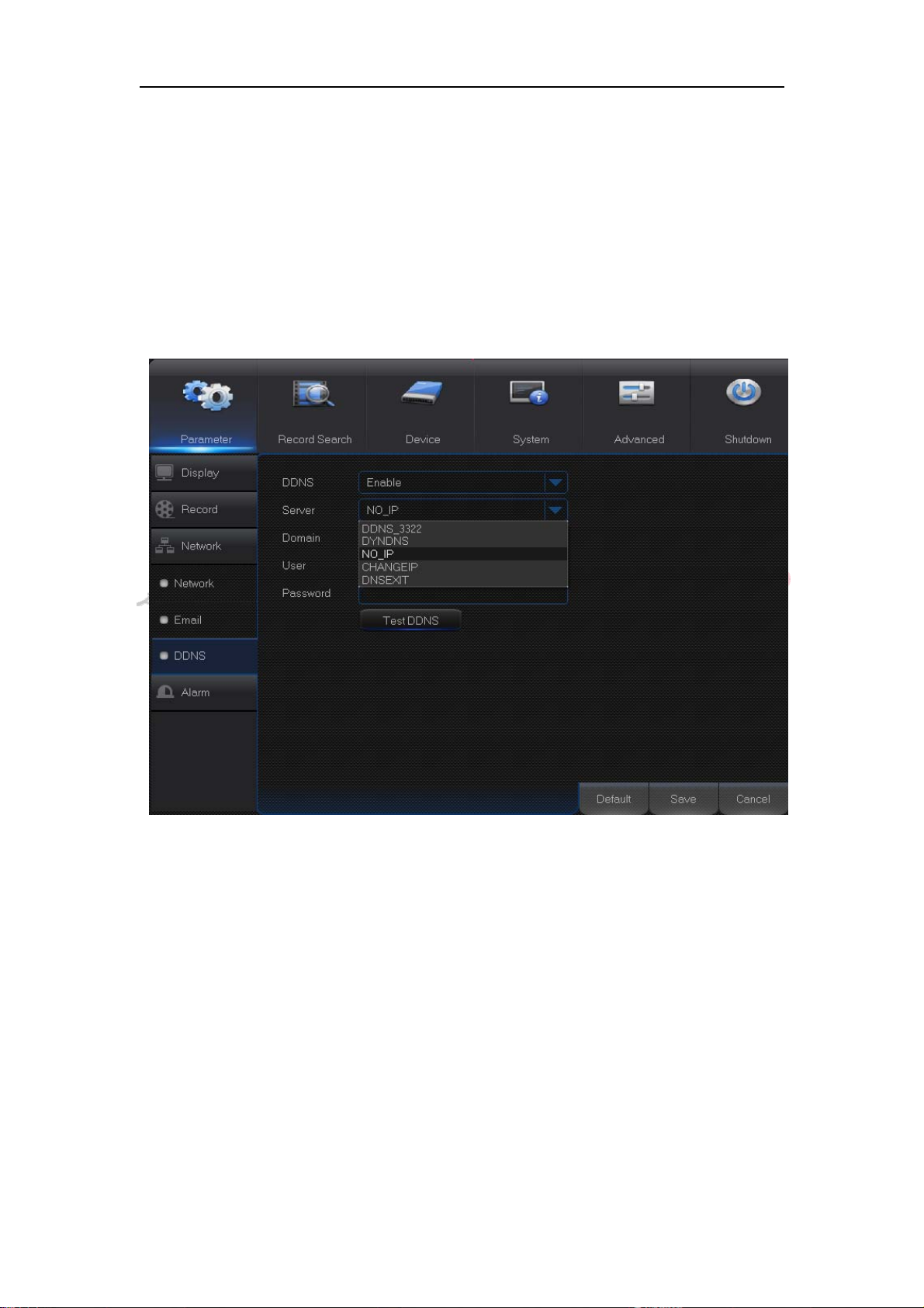
4.2.1.3.4 DDNS
Go to “Main Menu”→“Parameter”→“Network”→“DDNS” to enter into the menu interface.
User may set DDNS in any one of the above network connection after applying dynamic
domain service. User may remotely access NVR through domain by using browser in the
form of http://applied domain: mapped Web port number. When using DDNS domain
name to access NVR, user shall confirm that the port can be normally connected to
current IP on the public network and the settings for server address/host
name/user/password/setting should be consistent with NVR local setting.
21
Page 27
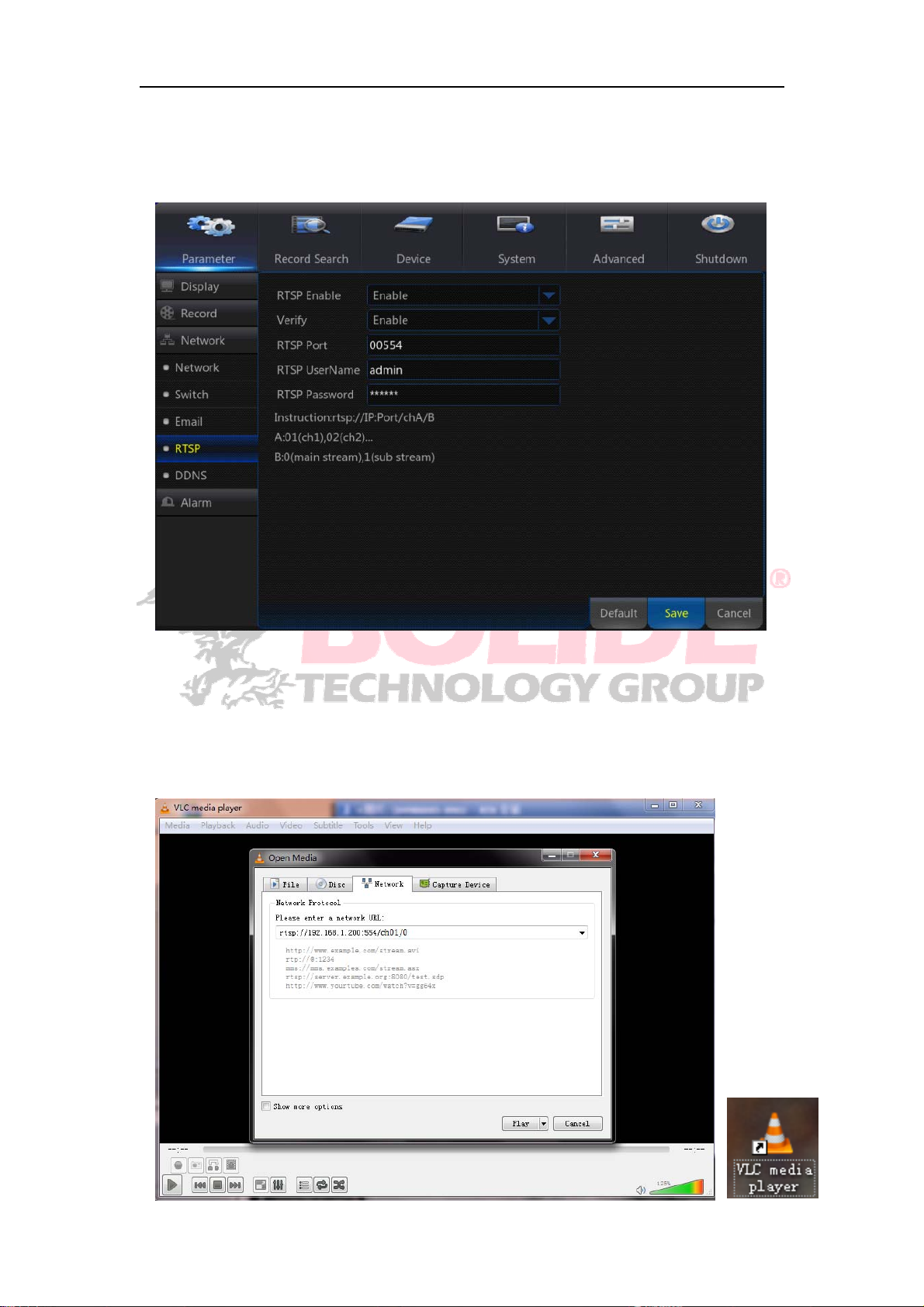
4.2.1.3.5 RTSP
V
/
A
Go to “Main Menu” → “Parameter” → “Network” → “RTSP”. Set user name and password
to view video by PC software VLC
RTSP Enable: Enable/Disable
erify: Enable/Disable
RTSP Port:
RTSP User Name: admin
Follow the instruction to input IP and port to preview video.
00
554
RTSP Password:111111
Instruction: rtsp:
B: 0(main stream),1(sub stream)
/IP:Port/chA/B
: 01(ch1), 02(ch2)...
22
Page 28
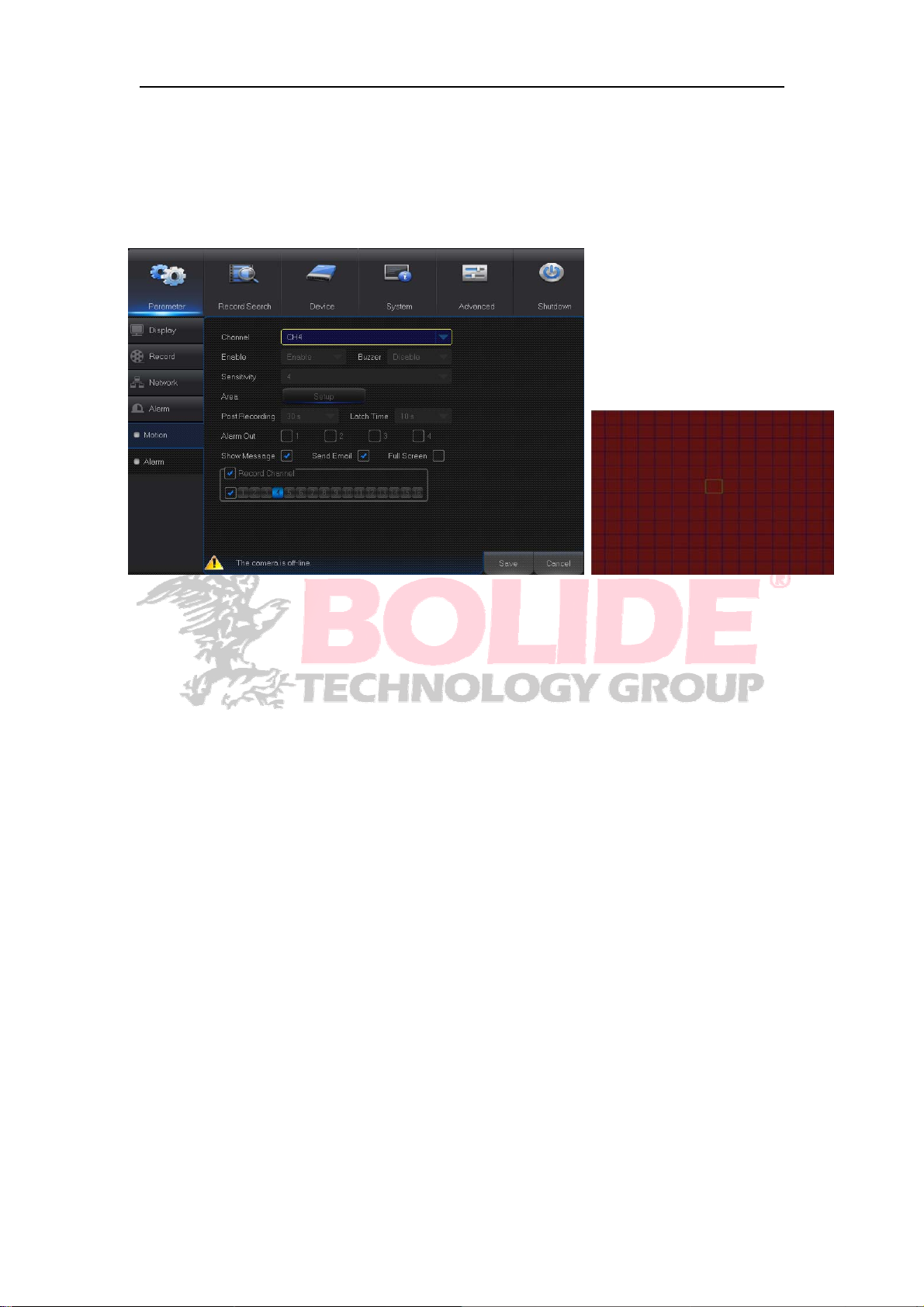
4.2.1.4 Alarm
4.2.1.4.2 Motion
Go to “Main Menu”→“Parameter ”→“Alarm”→“Motion” to enter into the interface.
Channel: Enable or disable Motion function.
Sensitivity: Support 1-8 level, 8 is the highest level.
Buzzer: When detecting object moving, buzzer makes alarms (disable, 10 seconds,
20 seconds, 40 seconds and 60 seconds).
Alarm Out: Connect to the alarm switch of the alarm apparatus.
Show Message: Messages will be displayed on the screen when moving object is
detected and alarms are made.
Send Email: When moving object is detected, send Email to the specified Email
address.
Full Screen: When moving object is detected, mes sages will be displayed in full
screen.
Latch Time: When moving object is detected, the alarm time can be set as 10
seconds, 20 seconds, 40 seconds and 60 seconds.
Post Recording: After the alarm finishes, the duration time of the alarm recording
can be set as 30 seconds, 1 minute, 2 minutes and 5 minutes.
Area : Click it to enter into the interface to set the motion detection area to be
monitored intensively.
A single channel is divided into 20ⅹ15 configurable grids. The red grids i ndicate that
the motion detection in the area is enabled, white semitransparent ones indicates that
the motion detection in the area is disabled. After setting is completed, right click the
mouse button to return and click Save to make the parameter setting effective.
23
Page 29
Record Channel:When object motion is detected, the record channel setting will be
y
y
)
)
y
y
f
activated.
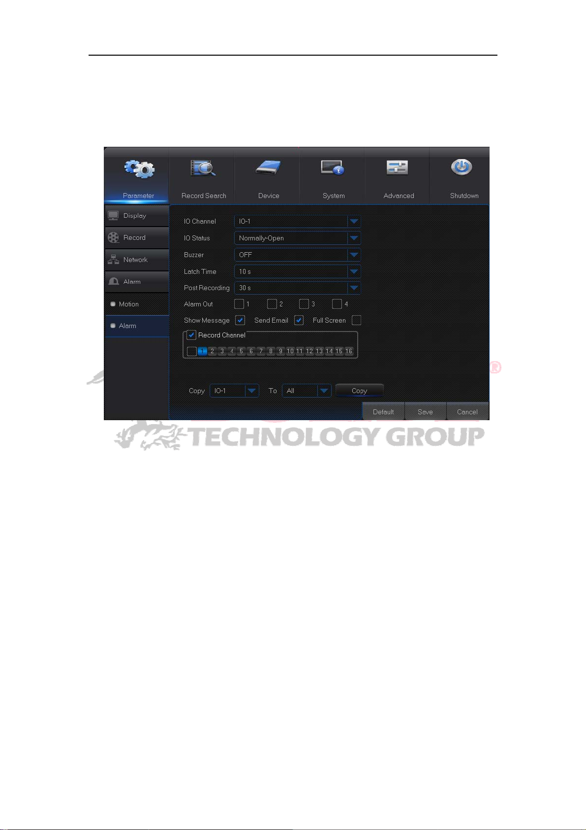
4.2.1.4.2 Alarm
Go to “Main Menu”→“Alarm”→“Alarm” to enter into the interface.
It is the alarm management and setting of the machine. User may set alarms under
different status in the interface. Please refer to Table 2-4
Alarm In: User may set four groups of alarm input.
Alarm Type: There are three kinds of status, i.e. Always ON, Always OFF, and OFF.
Always ON: When the trigger is on, I/O alarm appears; Always OFF: When the trigger
is off, I/O alarm appears; OFF: Do not receive I/O alarm from trigger.
Buzzer Time: You can set how long the buzzer will sound when motion is
detected(off, 10s, 20s, 40s, 60s)
Alarm out: Connect the external alarm switch.
Show Message: Display the alarm messages on the screen when motion alarm is
detected.
Send Email: Set to send email to specified email when motion alarm is detected.
Full Screen Alarm: When the motion is detected, the corresponding channel will be
switched to the full screen mode.
Latch time:
detected b
Post Recording: You can set how long alarm record will last when alarm ends (30s,
1minutes, 2minutes, 5minutes
Record Channel: The record channel will be activated when the object move is
detected.
Cop
: Allow
record channel cannot be copied).
ou can set how longthe buzzerwillsoundwhenobject move is
external sensor(10s, 20s, 40s, 60s
.
ou copycurrent channel parameters to anyother channel(settingo
24
Page 30
Alarm Type Functions & Descriptions
Video Loss
Motion
Detection
I/O Status
HDD Status
When NVR fails to receive video signals due to some problems (camera damage, line
dropout or damage, power failure), the alarm will appear.
When IP camera detects object moving, alarm will be activated. Sensitivity is subject to
the actual application environment test. Sensitivity is adjusted according to the
sensitivity of moving object detection and parameters are modified by combining the
area setting.
Communicate with alarm device through I/O port. Alarm signals sent by IR sensor or
other devices will be transformed to the system recognized signal and activate relevant
channel to record or control the device output.
Alarm will appear when HDD does not work due to damage, power failure, HDD
auto-overwrite off and insufficient space.
Tabl e 2 -4
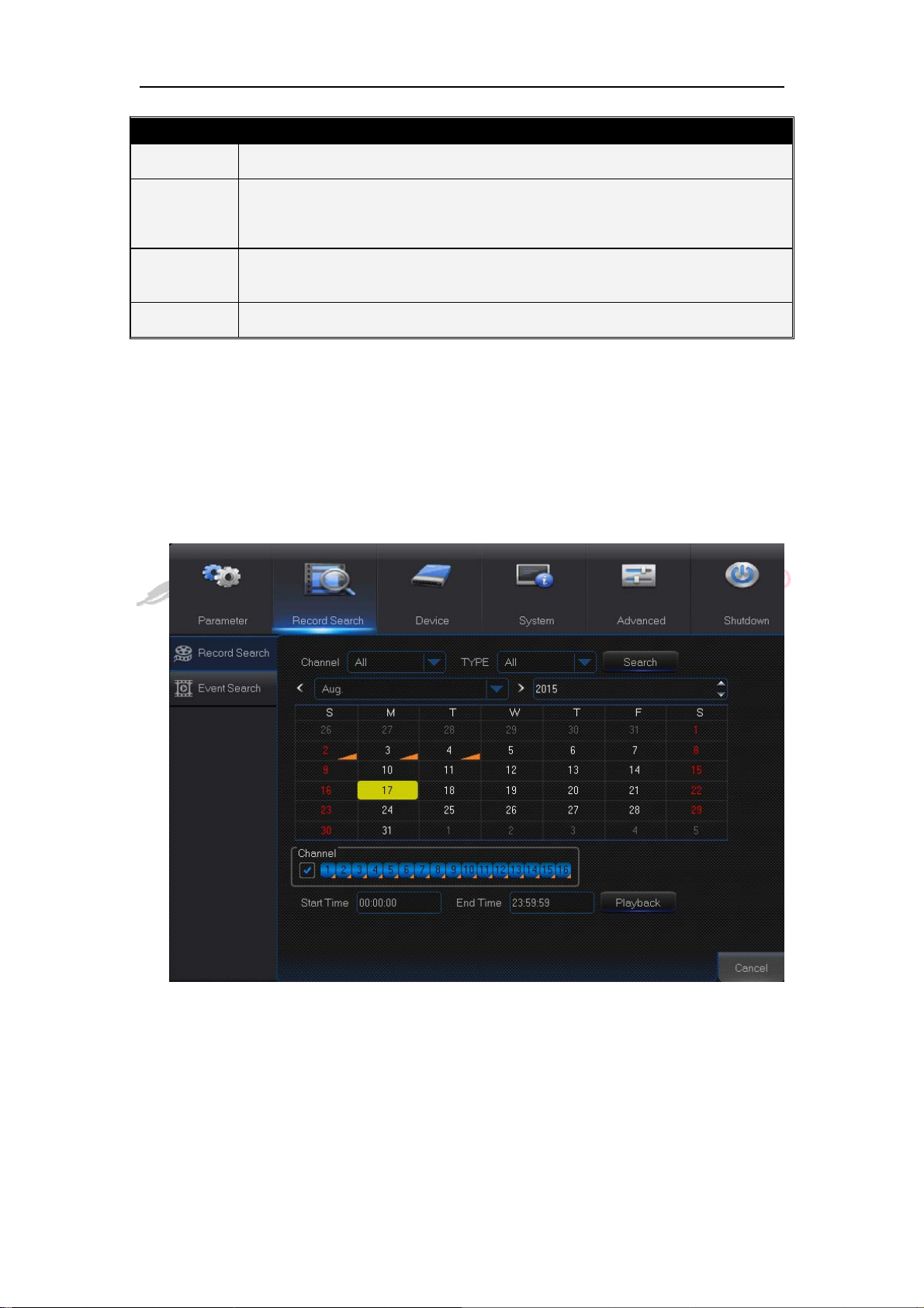
4.2.2 Record Search
4.2.2.1 Record Search
Go to “Main Menu”→“Record Search”→“Record Search” to enter into the interface .
Channel: Select the channel you want to search.
Type: Select the type the playback record. There are two options, i.e. Normal and
Alarm.
Start Time/End Time: Select the specific period of time. The default setting is from
0:00 to 24:00.
Playback Channel: Click a date and select corresponding channel in Playback
Channel. The selected channels shall not be more than 16.
25
Page 31
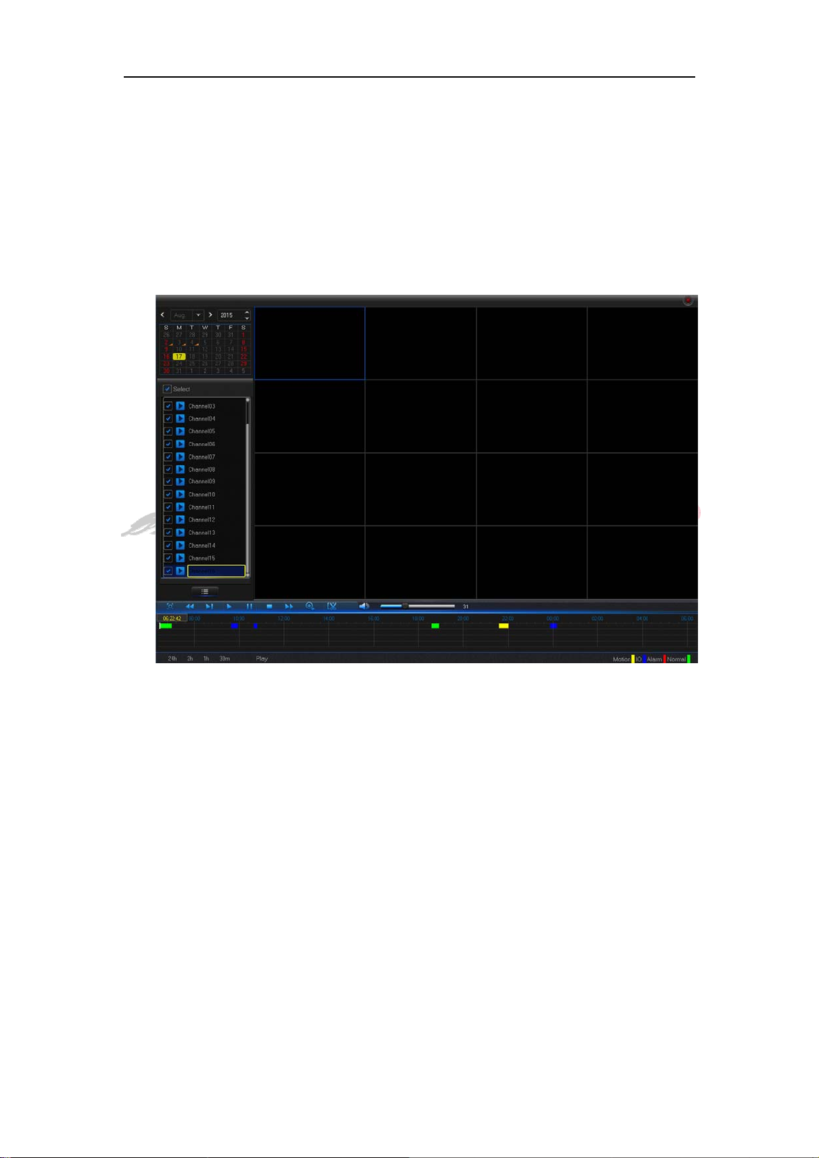
Playback: Select the desired year and month and click “Search”. If there are any
records, a yellow corner mark which shows the recording at specific date will appear
at the down-right corner of the date sheet. Select the date checkbox and select
playback channel and click Playback to enter into the interface.
Playback interface: You can use the Playback Control bar to operate the Fast
Forward (X2, X4, X8 and X16), Rewind (X2, X4, X8 and X16), Slow play (1/2, 1/4 and
1/8 speed), Play, Pause/Frame. You can click or drag the volume control bar to adjust
volume. When playback ends, NVR will remain in the playback interface.
26
Page 32
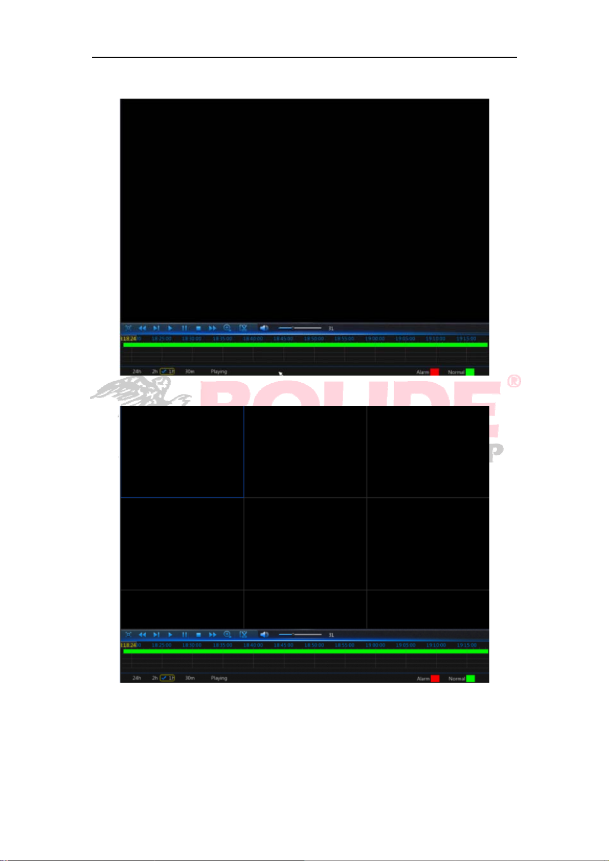
Time Axis setup, file clip and zoom in/out
1) The NVR supports the processing control bar function when playing back record files
Time Axis zoom: Default value is 24hours. Allow user to select 2 hours, 1 hour, 30
minutes or user-defined.
27
Page 33
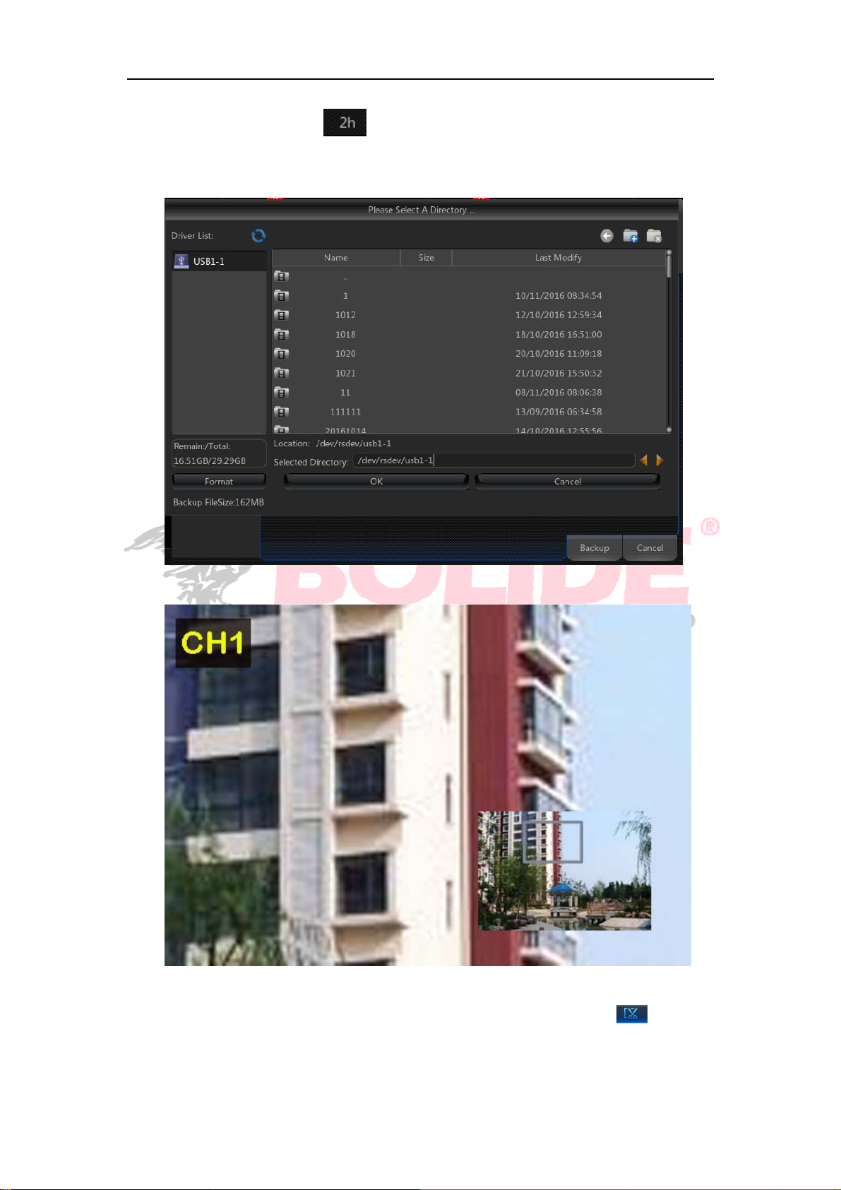
Detailed operation:
Fixed time axis: If you select [ ] option, that means the processing control bar cover
two-hours video content. The time range refers to 1 hour before and after the middle point.
2)Record clip and backup function and playback zoom in/out function.
Clip and backup:When it is under single channel playback, the [ ] icon will
appear in the Play Control bar. Click the icon to start video clip function, click the icon
again to end the function and pop up the dialog. Now, you may save the clipped video
28
Page 34
file.
Zoom out:When it is under single channel playback, the icon will appear in the
Play Control bar. Click the icon to zoom in certain area of the playback screen and
right click mouse to return the Playback page.
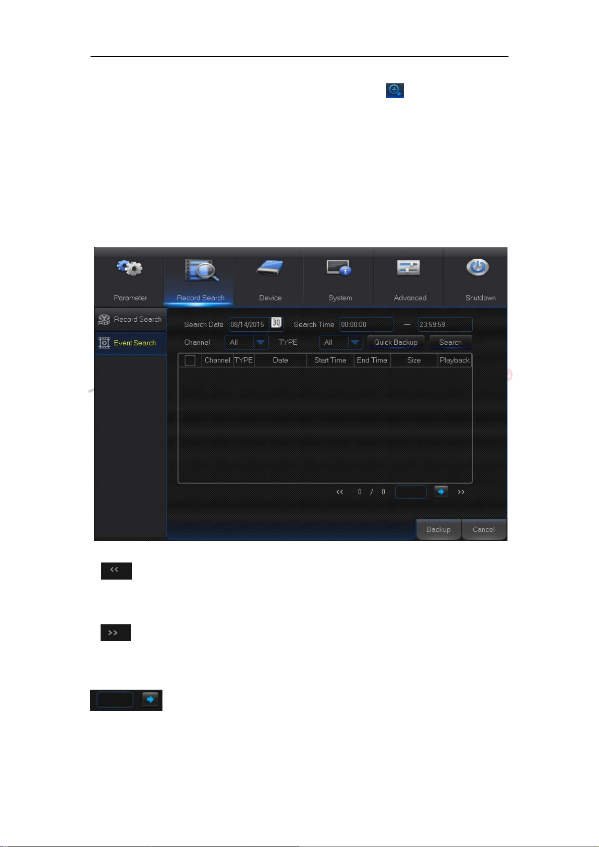
4.2.2.2 Event Search
Go to “Main Menu”→“Record Search”→“Event Search” to enter into the interface.
In this page, user may search details by date, time, channel and record type. The
relevant operations are as follows:
: Previous page; Click the button to go to previous page when viewing events
(except the first page). When viewing the first page, click this button to display the event
list in the first page.
: Next page; Click the button to go to next page when viewing events (except
the last page). When viewing the last page, click this button to display the event list i n the
last page.
: Jump; Input the desired record event page in the input box and click
arrow button to jump to the input page.
Two types of backup:Quick Backup and Backup
If you want to back up a record in the detailed file list, you may tick the checkbox at the left
29
Page 35
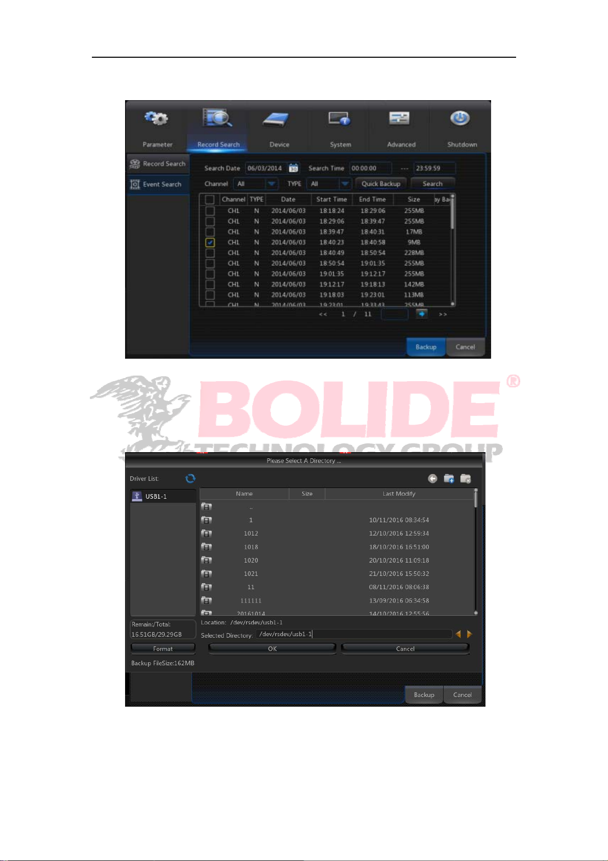
of the record (“√”means it has been selected) and click “Backup” to enter into “Select
backup type” (Make sure U disk or other portable storage device are connected).
If you want to back up with USB, select USB and click OK to start processing and you
may see the backup progress.
After backup finishes, message Backup Finishes will appear at down-right corner..
Note: Before backup, connect devices for backup (U flash disk or other devices with USB
interface)
30
Page 36
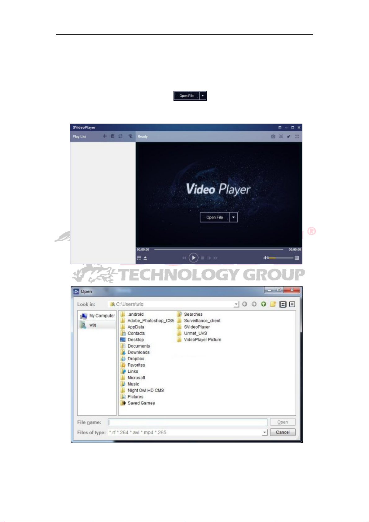
4.2.2.3 Play Backup Files
1.Copy backup files to the computer.
2. Open playback player and click “+” or“
*.rf, add backup file and select a file to play.
”. For example, if you want to choose
31
Page 37

Play: Click to play file
Pause: Click to pause
Stop: Click to stop playback
Step Forward: Play frame by frame
Slow Forward: playback in lower speed; the regulation sequence is 16×, 8×, 4×, 2×,
1/2, 1/4, 1/8, 1/16
Fast Forward: playback in higher speed; the regulation sequence is 16×, 8×, 4×, 2×,
1/2, 1/4, 1/8, 1/16×
Open file
Display/hide file list
Full screen display
Never stick on top
Always stick on top
Stick on top during playing
Capture: Save path: installation directory\SVideo Client\picture
Cut video
Adjust volume
Window Division: Playback in multiple screens;
Playback in 1, 4, 9 or 16 windows is optional
Open File
Clear List
Play Mode: Single, Order, Repeat One, Repeat All are optional
Search File
Advanced configuration: Set language, parameters and About information
32
Page 38
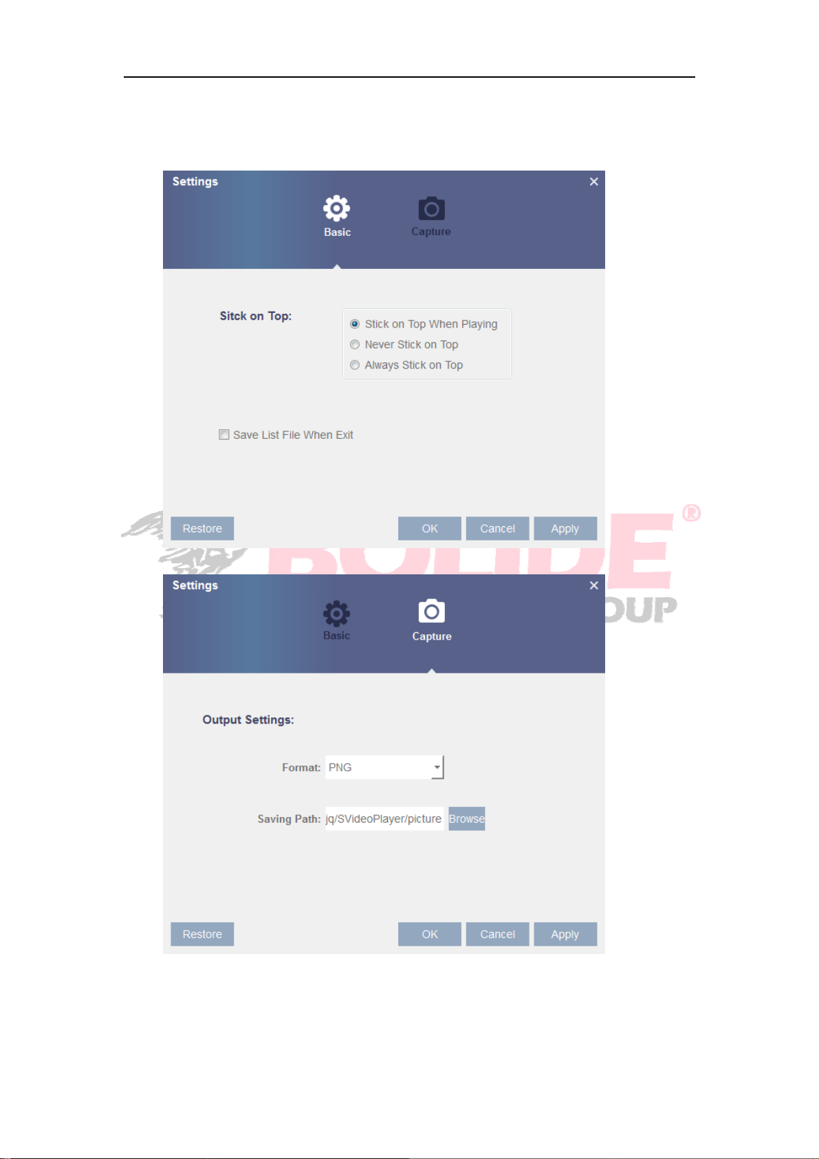
Basic Settings: Set on-top mode
Capture Settings: Set the path to save image
Note: It is recommended to use SVideo Player contained in compact disk for playback.
Use of any other player may cause compatibility problem.
33
Page 39
4.2.3 Device
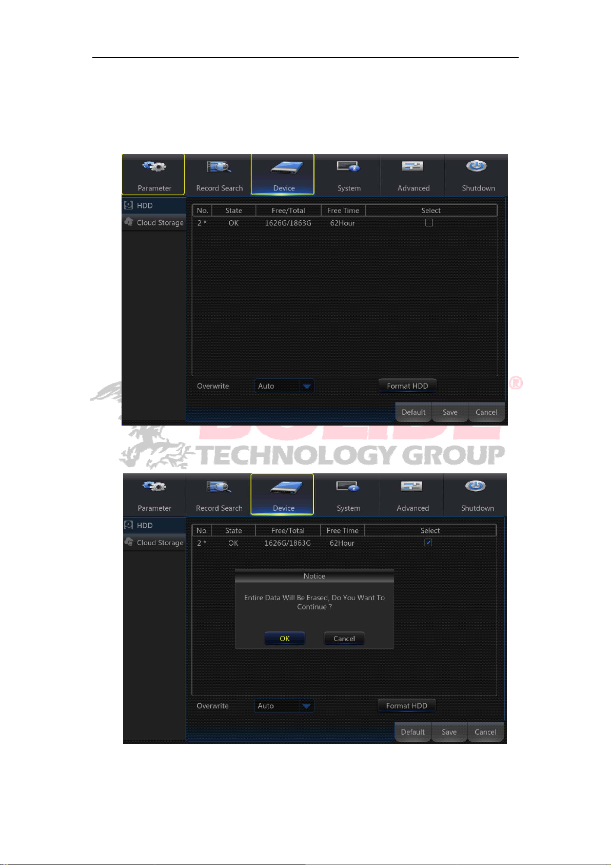
4.2.3.2 HDD
Go to “Main Menu”→“Device”→“HDD” to enter into the interface.
When NVR is connected to a HDD, the system will automatically detect if HDD is
34
Page 40

normal or not; If HDD need to be formatted, status will be shown as “Not formatted”.
Select the HDD and format the HDD. If the system detects HDD is normal state, the
HDD status will be shown as “Normal”.
No.: Number of HDD connected to system.
Status: It shows the current status of HDD. It will be available only when HDD is
“Normal”.
Free/Total Space: Remaining or total space of HDD
Free Time: Remaining time for HDD recording according to currently set “Resolution” ,
“Encoding Rate” and “Frame Rate” of image.
Auto-overwrite: When set to ENABLE, the NVR will overwrite the oldest files on the
hard drive if hard drive space is full. When set to DISABLE, the NVR will stop
recording if hard drive space is full. Overwrite time: 1 day, 3 days, 7 days, 14 days, 30
days and 90 days. It means the longest storage time of records in HDD. If the time is
over, the records will be deleted. For example, if the time is set as 3 hours and the
data in HDD include 12, 13, 14, 15, 16, 17, 18, 19 and 20 o’clock, then data 18, 19
and 20 will be saved and data 12, 13, 14, 15, 16 and 17 will be deleted.
Format HDD: Format HDD for the first use.
Note: Recording can only be performed when HDD is in “Normal” state.
4.2.3.2 Cloud Sorage
Cloud Storage (Network HDD)can upload videos to your Dropbox account.
1) Register in Dropbox website, Address: https://www.dropbox.com/
2) Configure network to ensure the normal operation of NVR network.
3) Configure Cloud: Enable Cloud and set the channel and interval for the NVR to
periodically captured pictures; Enable Motion Detection to get captured pictures for
motion detection.
4) Driver Name refers to the name created in the folder of Dropbox and the name can be
defined by the user, e.g. CloudNVR. The folder is to store the NVR periodically
captured pictures).
5) Click [Advanced E-mail Setup] to set the Email box. User shall input his Email.
6) Click [Active Cloud] to activate Cloud and Email will receive the URL related to Cloud
User input the registered user name to visit the above website and the following
interface will be popped up.
7) Click the icon at the upper-left to view the folder (CloudNVR) referred to in Step 4.
35
Page 41
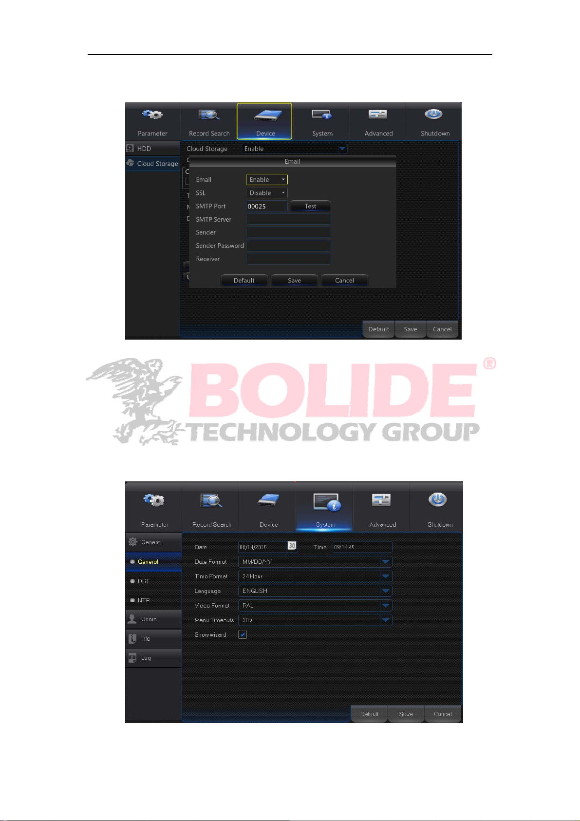
8) Enter the folder to view the NVR captured pictures.
9) Click [Upgrade Cloud storage] to Check and update the new version.
4.2.4 System
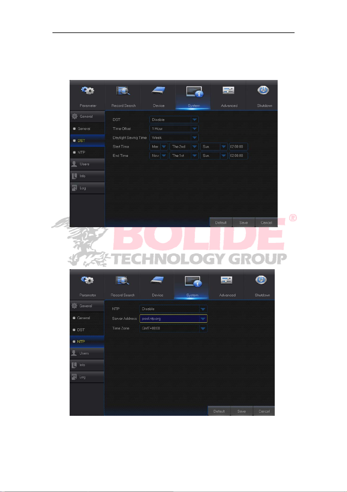
4.2.4.1 General
4.2.4.1.1 General
Go to “Main Menu”→“System”→“General” to enter into the interface. User may set
Date, Time, Date Format, Time Format, Language, Video Format, Menu Timeouts and
Show Wizard in this page.
36
Page 42
4.2.4.1.2 DST
Go to “Main Menu”→“System”→“General”→“DST” to enter into the interface. Enter
into the interface to set DST, Time Offset, Start Time and End Time.
4.2.4.1.3 NTP
Go to “Main Menu”→“System”→“General”→“NTP” to enter into the interface.
37
Page 43
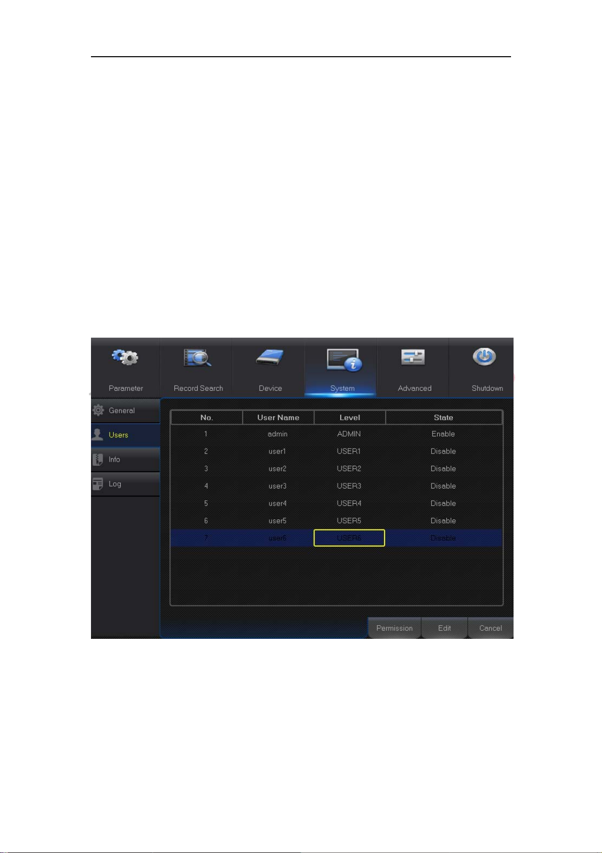
NTP service: Enable/Disable NTP function.
Server Address: Select NTP server(time.windows.com, time.nist.gov, pool.ntp.org).
Time Zone: Corresponding time zones for various nations or regions.
Update Time: Enable NTP function and save parameters and click Update Time to
calibrate the system time.
Note: When NTP function is set to “Enable”, system will calibrate the system time at
every 00:07:50 and every start-up.
4.2.4.2 Users
Go to “Main Menu”→“System”→“Users” t o enter into the User interface.
It supports up to seven users, including one administrator and six users. Click [Edit]
button to enter into the [User Edit] interface to input user name and password.
User Name consists of 8 characters and password is composed by number 0-9 with
max length of 8 numbers
38
Page 44
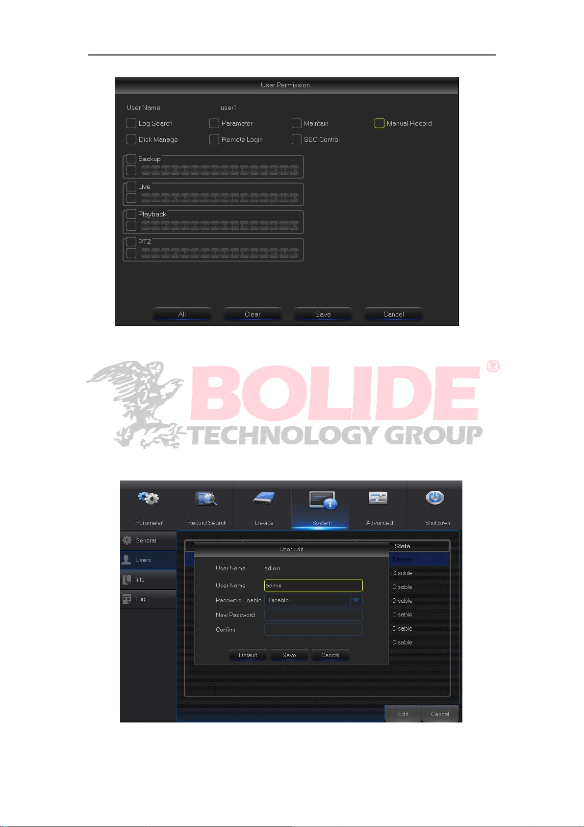
Set user password. Administer is authorized to set user common user’s authority.
Log Search: allow you check all the system logs.
Parameter: allow you set all the parameters.
Maintain: allow you update version, recover ex-factory value, device reboot and shut
down.
Disk Management: allow you manage and control the HDD and USB drive.
Remote Login: allow you remotely login NVR.
SEQ Control: allow you sequence live screens for all the channels.
39
Page 45
Manual Record: allow you manually start/stop record.
Backup: Tick-select the ENABLE option and select channel for backup, the user is
allowed to backup the record in the selected channel.
Live: Tick-select the ENABLE option and select a channel and the user is allowed to
view all the live images in the selected channel.
Playback: Tick-select the ENABLE option and the user is allowed to playback the
selected record in the channel.
4.2.4.3 Info
4.2.4.3.1 Info
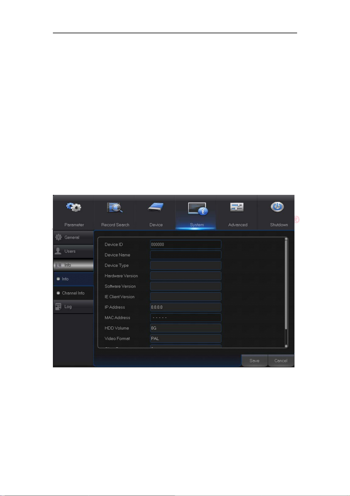
Go to “Main Menu”→“System”→“Info” to enter into the interface.
User can view system information, including Device ID, Device Name, Device Type,
Hardware Version, Firmware Version, IE Client Version, IP Address/Domain, MAC
Address, HDD Capacity, Video Format, Media Port, Web Port, etc.
40
Page 46
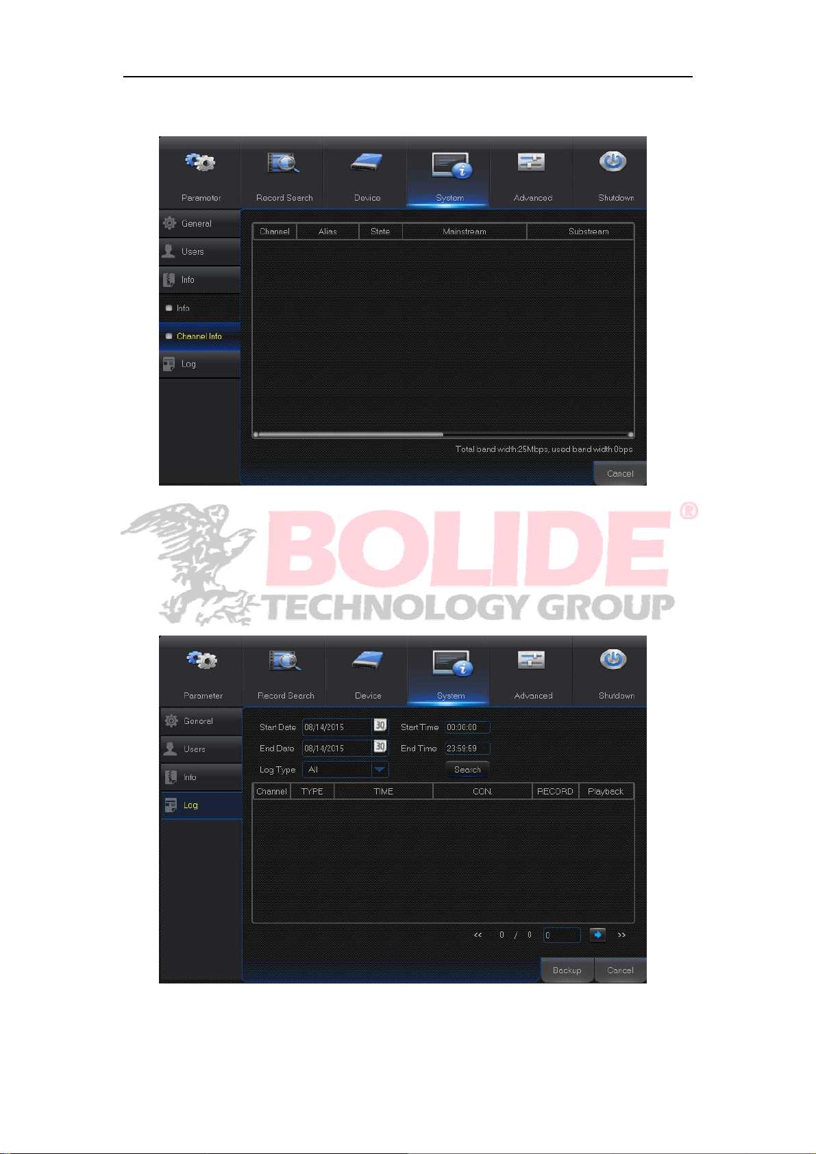
4.2.4.3.2 Channel Info
Go to “Main Menu”→“System”→“Info”→“Channel Info”.
User may view the information of various connected IPC, including state, mainstream,
substream, motion detection, privacy zone, cruise, etc.
4.2.4.4 Log
Go to “Main Menu”→“System”→“Log”.
User may search log information in different period of time. Click “Backup” to save all the log
information.
41
Page 47
4.2.5 Advanced
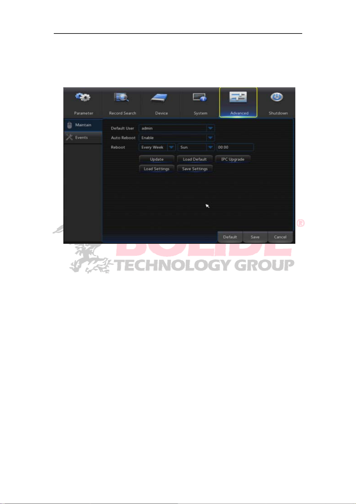
4.2.5.1 Maintain
Go to “Main Menu”→“Advanced”→ “Maintain” to enter into the interface.
Auto Reboot: Enable the auto maintenance function to reboot system regularly at
every day/week/month. When Auto Reboot is enabled, NVR should be in the main
interface and no user operation.
Upgrade: Decompress update file package and copy the upgrade file folder named
“nvrupgrade”(The upgrade program is inside) to root directory of U flash disk; Insert
the U flash disk into USB port of NVR; Click <Upgrade>.
Load Default: If [Load Default] is selected, you can initialize the system to the
ex-factory default. Click “Load Default” and select items to be restored
Load Settings: Load parameters in the removable storage device to NVR.
Save Settings: Save the set parameters of user’s NVR to the removable storage
device.
IPC Upgrade : IPC can be upgraded by the connected NVR. Decompress IPC
upgrading file and copy *.sw file to nvrupgrade directory and copy to the root directory
of U flash disk, Insert the U flash disk into USB port of NVR—>Select the IPC you
want to upgrade—>Click Upgrade to start upgrading IPC.
Note:Do not take out the USB memory or cut off the power during upgrading. When
the update is done, system will be automatically restarted. After about 5 minutes, the
upgrading will be finished. It is recommended to load ex-factory default after upgrading.
The auto maintain function can be effective only when NVR returns back to Preview mode
42
Page 48
with no any operation within the set auto maintain time.
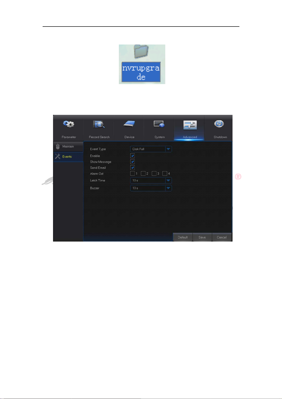
4.2.5.2 Events
Go to “Main Menu”→“Advance”→ “Events” to enter into the interface.
Event Type: Support three abnormal types: Disk Full, Disk Error and Video Loss.
Enable: Active alarms for abnormal situations.
Alarm Out: Enable or disable alarms
Latch Time: How long the buzzer will sound when external sensor alarm is detected
(10s, 20s, 40s, 60s).
Show Message: You can set show message on the screen when sensor alarm is
detected.
Buzzer: How long the buzzer will sound (10s, 20s, 40s, 60s).
Send Email: Select to send Email to specified Email address when abnormal events
appear..
43
Page 49
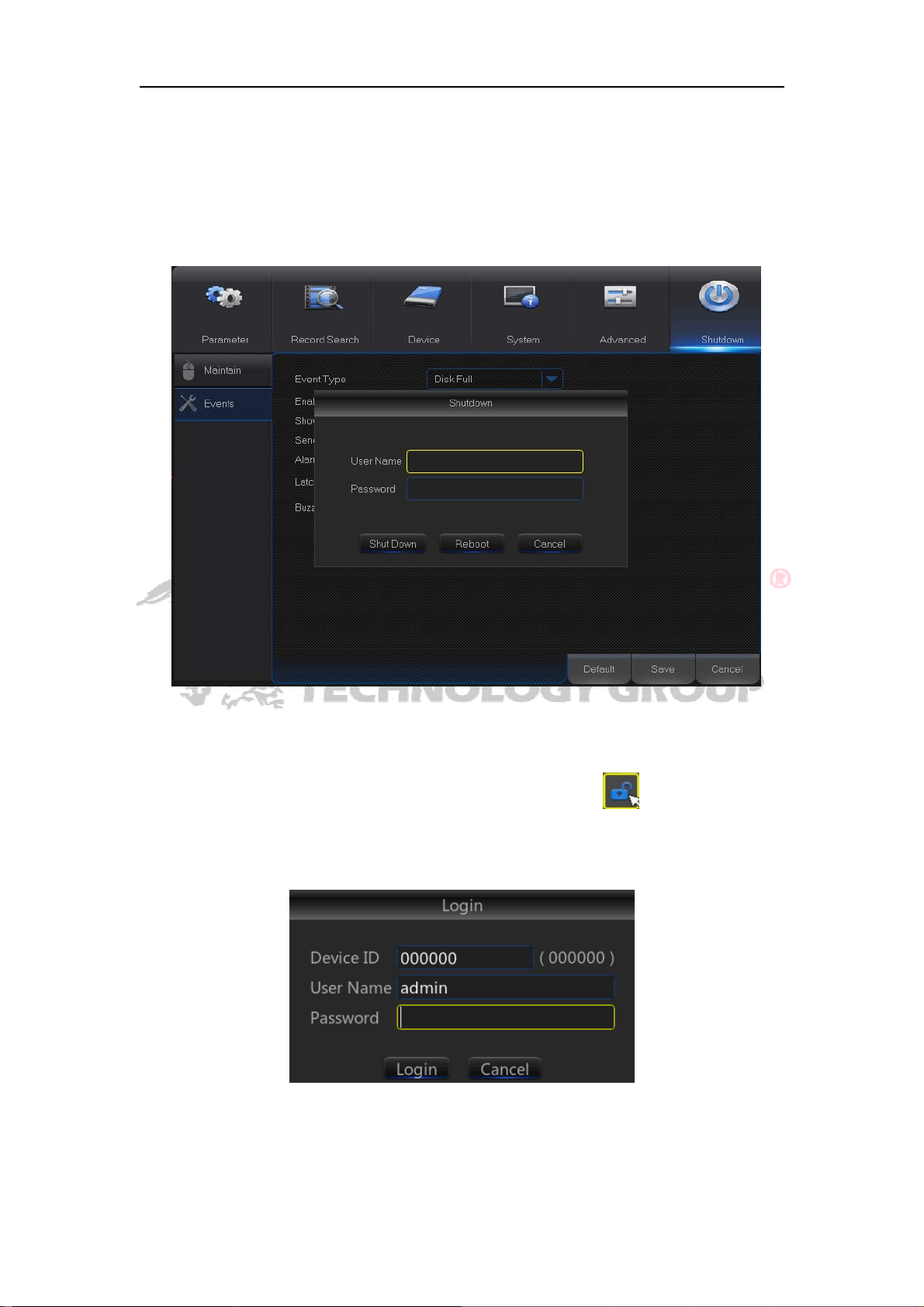
4.2.6 Shutdown
Go to “Main Menu”→“Shutdown” to enter into the menu interface.
Shutdown function requires user to login by inputting User Name and Password so
as to shut down or reboot system.
4.3 Menu Lock
In consideration of system safety, user may click the icon on the toolbar when
he leaves away from NVR and the system interface will be locked. User has to input
Device ID, User Name and Password on the login interface to unlock(Default: User
Name: admin, Password: blank).
Note:Administrator has all authorization of menu operation and users have limitations for
authorization and have to get authorization from administrator.
44
Page 50
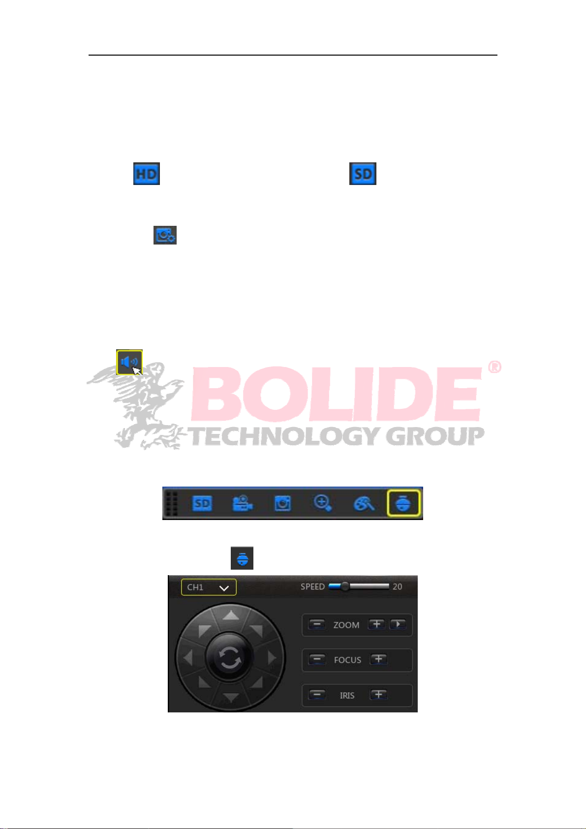
4.4 Split Mode
There are many display modes in video channel, including single channel display, SEQ
display and split mode.
4.5 Stream Switch
Click HD to switch to Main Stream, and click SD to switch to Sub Stream.
4.6 View Image Quality
You can click to switch among Real Time, Balanced and Smooth.
4.7 Start Sequence
After set channel sequence time(Ref er to Chapter 4.2.1.1.3), click Start Sequence icon
on the toolbar to start sequence.
4.8 Mute
Click icon on the toolbar or Mute button on the panel or remote controller to control
the mute of NVR.
4.9 Start Cruise
Set the PTZ preset position for cruising:
In preview interface, click the channel which needs PTZ function, enter the menu of
the channel.
Click the Cradle Control icon ,entering the control platform.
45
Page 51
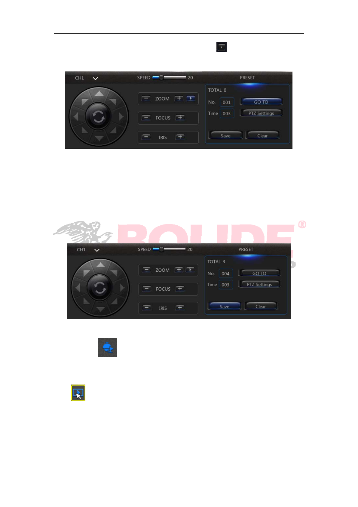
Click the triangle icon menu in Cradle Control platform , enter the interface for the
preset point.
The video screem can be moved to the direction of cruise point as you want by
controlling the eight direction keys in PTZ platform. You can modify the PZT time to
set the duration which PTZ will stay in one point. If there are mulitipe points want to
set, select the preset point according to the same method, then click “PTZ Setting”.
Pls note that the preset point statistic after “Total Preset” is correct, click “Clear” to
clear the current settings, then Save. Other channels can be set in the same way,
then the cruise route of the channel was set done.
Click the icon right below the preview interface, then PTZ will start to cruise
based on the planning route which you set.
4.10 Record Search
Click
playback. Refer to chapter4.2.2 for specific operating method.
icon on the toolbar to enter into the Record Search interface to search and
46
Page 52
Chapter 5 Web Application Manager
5.1 ActiveX control download and installation
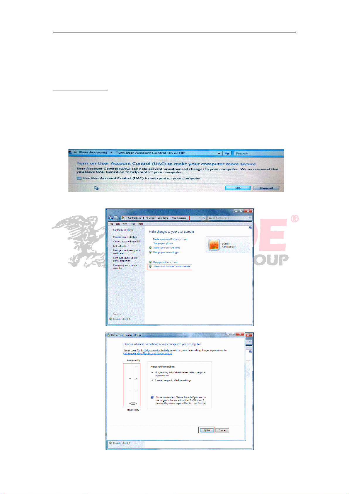
Open your web browser and input the IP address of NVR, such as:
http://192.168.1.168
“ActiveX” plug-in automatically. If your computer sys tem is Windows Vista or Windows 7,
you may need to setup the user authority for remote control, or you may be unable to
backup or record.
Vista System: Start→Setup→Control Panel. Set user authority in control panel (as
shown in picture below). Remove the Tick “√”infrontoftheoption“UseUACtohelp
protect your computer” and confirm OK.
WIN7:
. If your c omputer is connected to internet, it will download and install
Vista
WIN7-1
WIN7-2
47
Page 53
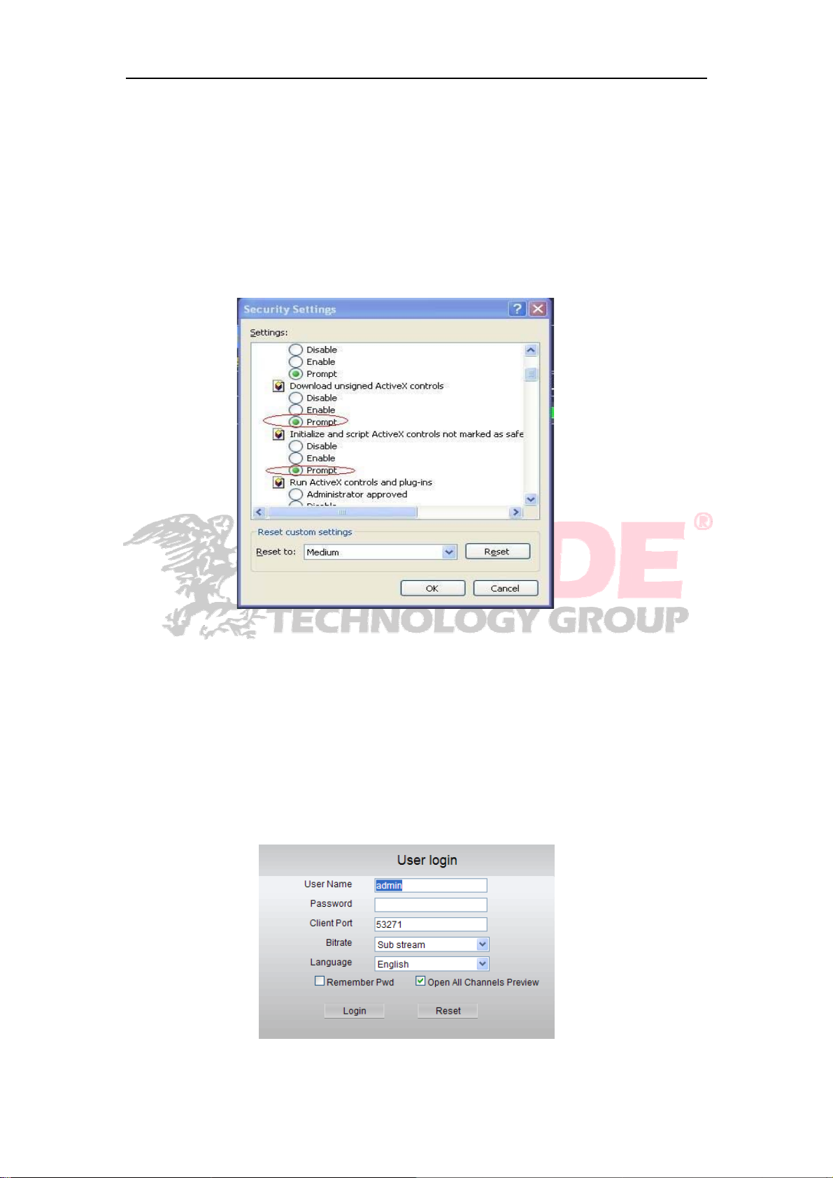
Note: If the ActiveX control is not downloaded successfully, please check if your browser’s
safety level or firewall setting is set too high. Please open IE browser→ [Menu
Bar]Tools→Internet options→ Security → Internet →Custom level→Enable the options.
If the web application runs for the first time, please wait for about one minute to finish
downloading.
If you want to use the undated ActiveX control at a computer which you have already
logged in before, please delete the original control and click [StartRun] and then input
the command characters: “regsvr32/u HiDvrOcx.ocx”. Press OK. When you log in at the
next time, new ActiveX control will be automatically downloaded. Please wait.
5.2 Web Application Manager Login
After ActiveX controls installation, please input user name and password, select
Main Stream or Sub Stream (In general, select main stream for intranet and sub stream
for outer net), and select language in the interface. There is an option for opening all
channel preview, select it to open all live pictures. Press Login to log in client and
remotely visit NVR. The default password is admin and administer is authorized to
modify the password. Set password as per introductions of user management in system
setting.
48
Page 54
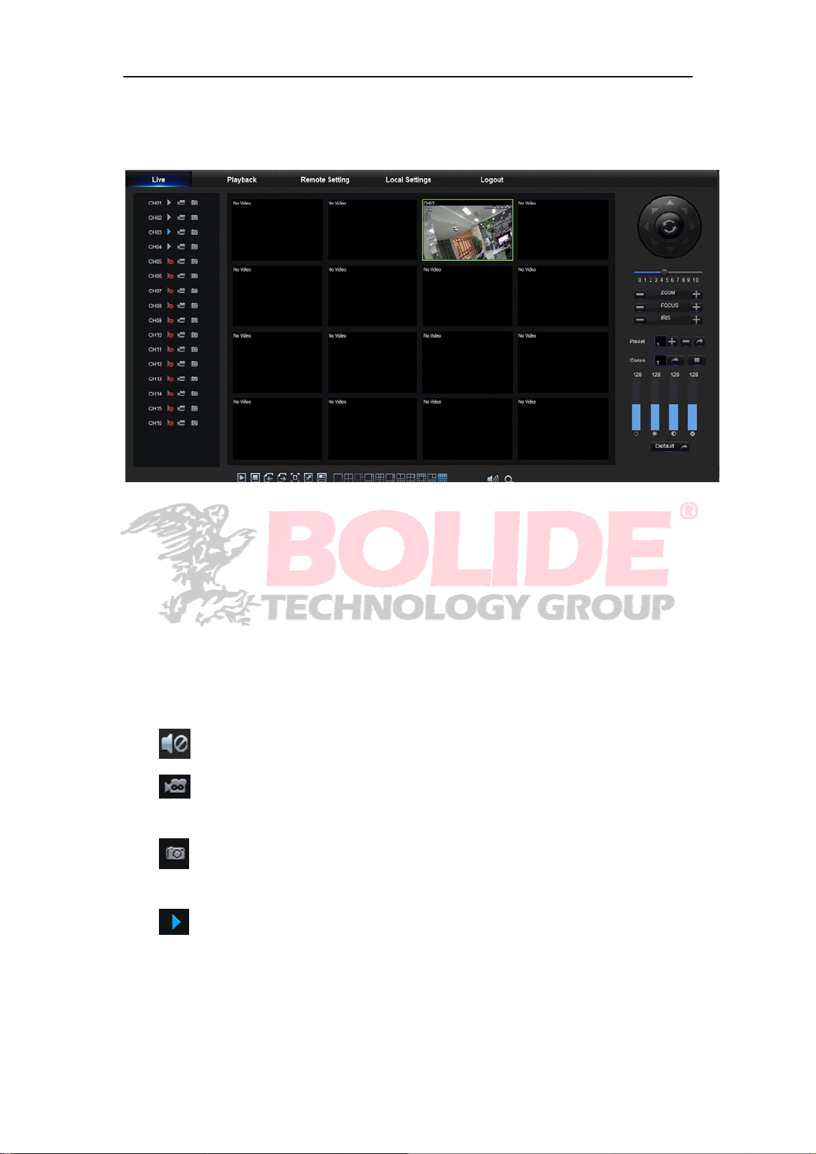
5.3 Live Interface
Log in and enter into the live interface to establish video link.
5.3.1Menu Bar
Menu Bar: Live, Replay, Configuration, Local Setting and Logout
5.3.1.1 Live Display
Log in the Web Application Manager, system will be defaulted to enter into <Live>
interface. You can click [Play] button to Open/close live images, on-spot record, capture,
and many live display modes.
Buttons on a single live interface:
:Volume switch
:Record switch: the remote record switch of client. Record will be automatically
saved to a specified position on PC after the function is enabled.
:Snapshot: Capture the selected live image and save it to a specified position
on PC. The image is saved as *.bmp format.
:OpenorclosetheimagesonLivewindow.
Or click the right key of mouse on each <Live> window to pop up channel operation
menu.
49
Page 55
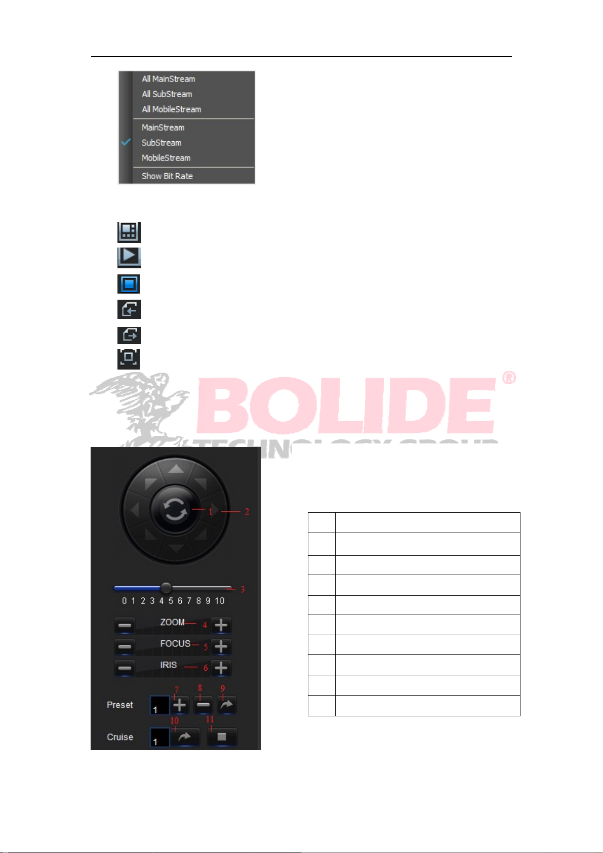
Show bit rate: Tick Show Bit rate to show IPC bit rate in current window.
:Switch display mode in channel window
:Open all the Live channels.
:Close all the Live channels
:Display previous group of channels
:Display next group of channels
:Click to maximize the current window to full screen. Right click to pop up menu
option and select Exit Full Screen.
5.3.1.2 PTZ
PTZ cruise, the specific parameters refers to the
1 turnover
the dome will cruise to the eight
2
direction
3 speed adjustment
4 Zoom in and out
5 Adjust the focus of the lens
6Iris
7\8 Edit the previous (later) preset
9 Jump to the preset point
10 Start to cruise
11 Stop to cruise
50
Page 56
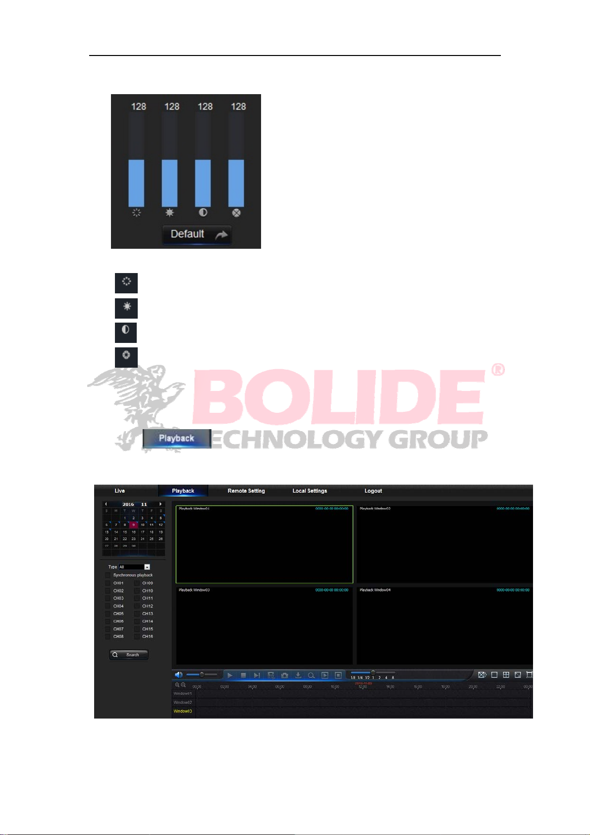
5.3.1.3 Video Control
:Adjust the chromaticity of video
:Adjust the brightness of video
:Adjust the contrast of video
:Adjust the saturation of video
5.3.2 Playback
Click to enter into Playback interface to remotely view the records in
NVR HDD.
It supports 4 channels playback.
51
Page 57
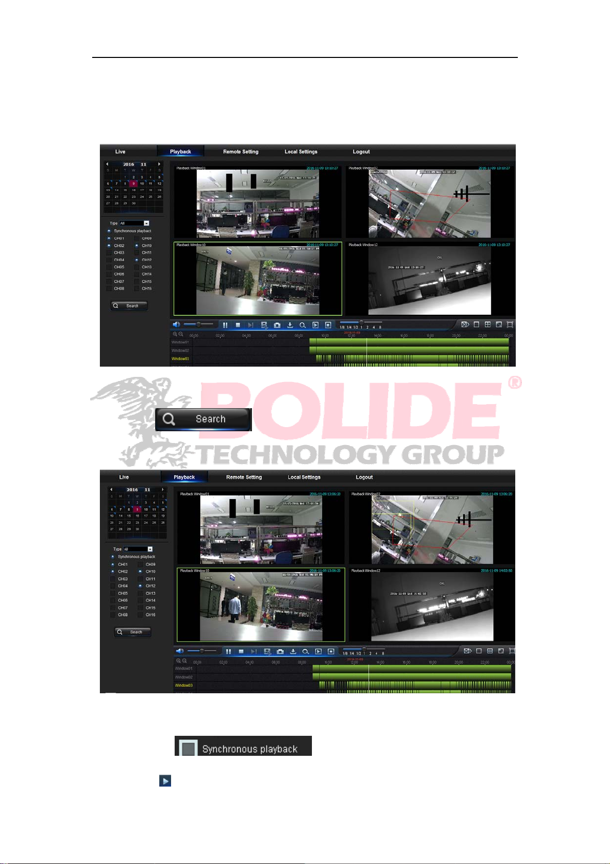
5.3.2.1 Record Search
Record playback procedure
Firstly, select the date you want to check and select 4 channels. Any record files in
current channel at current date will be displayed in the status bar of the interface.
Secondly, select record type (Normal record, Alarm record and All) and channels, and
then click “ ”,and time axis panel wil l display specific time quantum.
On the time axis, red part stands for alarm record, yellow stands for normal record and
original part stands for no record during this period.
Before playback, choose to enable playback 4 channels synchronously. If you
tick-select “ ” , that means the selected channel will
playback synchronously; otherwise, you could separately control the channels playback.
Thirdly, click to start record playback. When mouse curse is moving on the time axis,
52
Page 58
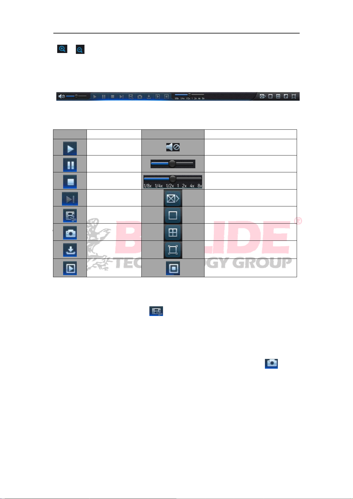
the time point of current position will be displayed on the time axis screen. Click the icon
or to zoom in/out the time bar display ratio.
5.3.2.2 Playback Control
Playback control bar.
Detailed brief description is shown as below list
Key
playback channels
Record file clip
Description
Play
Pause
Stop
By frame Stop playing all the files
Record Clip
Snap
Download Full Screen
Open all the
Key
Table 5- 1
Description
Enable the volume switch
Volume adjustment bar
Slow playing 1/2,1/4.1/8, Fast
playing 1/2/4/8
Single channel mode
Quad mode
Stop playing all the playback
After opening playback, click icon to clip the selected file; and click again to
stop the clip function. Then playback clip is successfully done. Record clip file will be
saved as *.264 format.
Snapshot function
Move the mouse curse to the channel you want to capture, and click [
capture the live images remotely. After capturing the images successfully, a path prompt
box will be popped up.
]iconto
53
Page 59
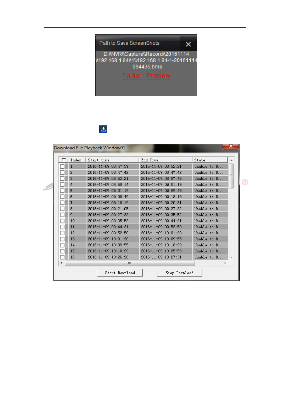
Thecapturedfilewillbesavedas.bmpformat.
Record file download
Click download icon “
according to the search conditions of channels.
” on the control bar to display all the matched record file
Tick-select the record file you want to download and click [Start download] .System will
download the record file in sequence and save to local PC. The downloading file will be
displayed in percentage form. After downloading finishes, “Complete” will be displayed on
the status bar.
5.3.3 Parameter Setting
Click Parameter Setting to enter into the interface , including Display, Record, Network,
Alarm, Devic e, System and Advance.
54
Page 60
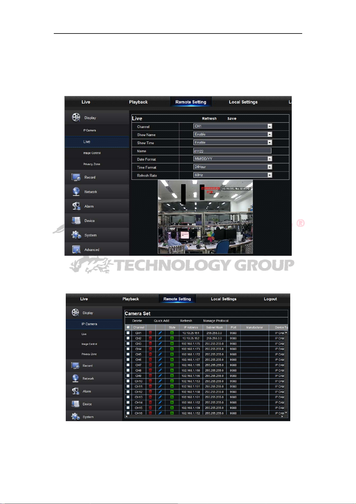
5.3.3.1 Display
Unfold [Display] option to find its sub-options: IP Camera, Live and Privacy zone.
1. Live: You may change channel name, position, channel preview and relevant
parameters. If show time is set as <disable>, current NVR system time will not appear
on the screen on Live mode.
2.IP Camera:Display the information of added IPC. It can quickly add the on-line IPC and
delete the added IPC.
55
Page 61
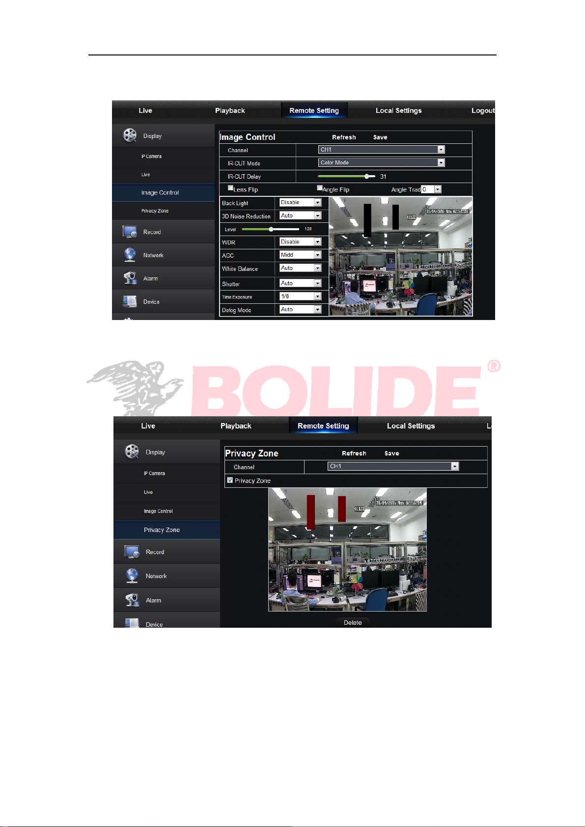
3.Image Control: You can configure some settings of IPC, such as white balance, 3D
noise reduction and image reversal etc.
4. Privacy Zone: Each channel can set 4 privacy zones.The relevant parameters
should be consistent with NVR local setting. Select zones to be deleted and click
“Delete” and click “Save” at up-right corner.
56
Page 62
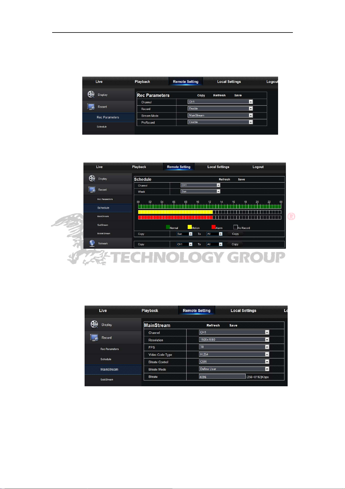
5.3.3.2 Record
Click <Record> option to unfold its sub-options: Record parameter, Schedule and Stream
configuration.
1. Record Parameters. The parameters should be consistent with NVR local setting.
2. Record Schedule. The parameters should be consistent with NVR local setting.
Green stands for Normal record; Yellow stands for Motion detection; Red stands for I/O
trigger record.
3. Stream setting. User may set Mainstream, Substream and Mobilestream. The
relevant parameters should be consistent with NVR local setting.
57
Page 63
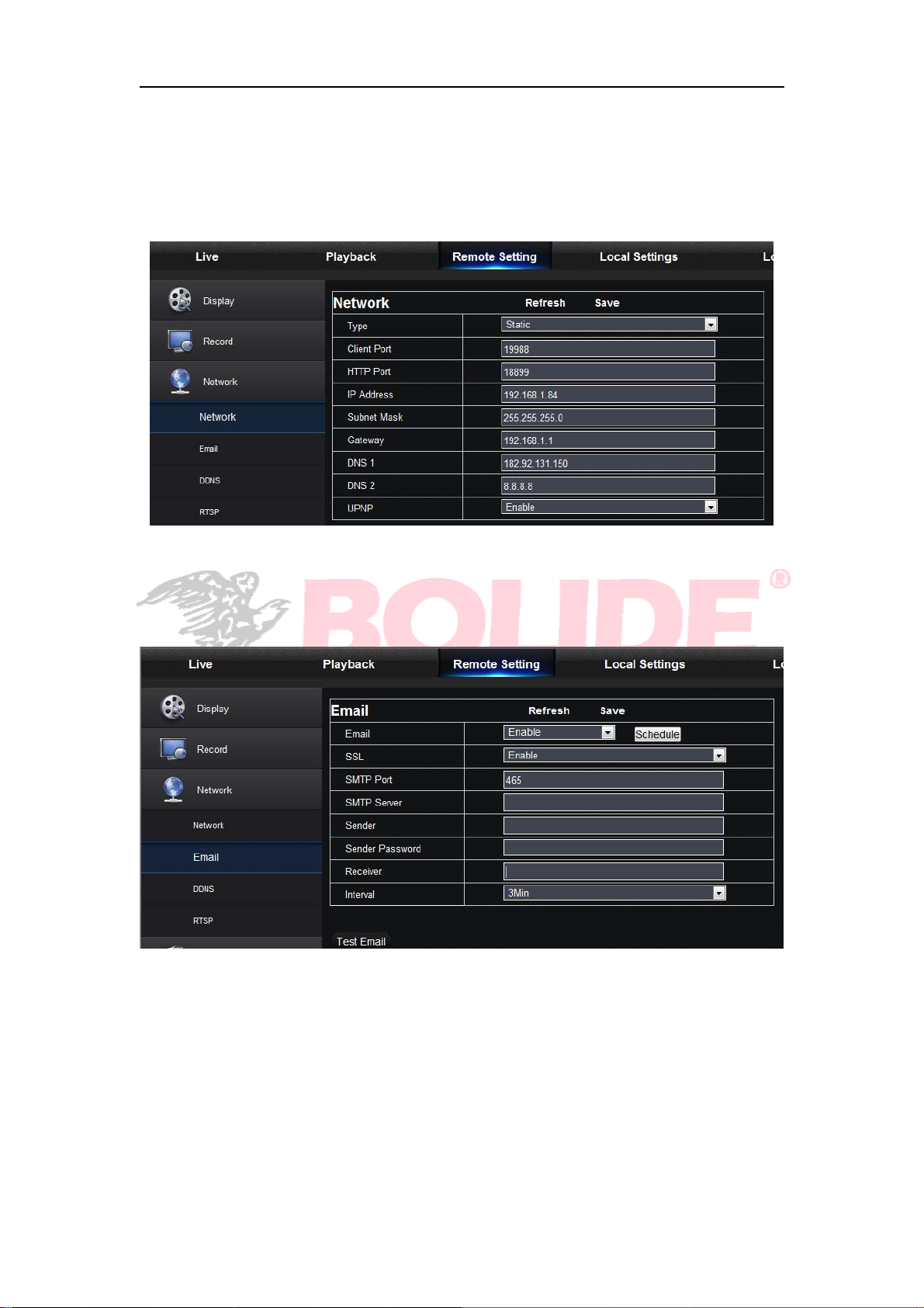
5.3.3.3 Network
Unfold <Network> to show its sub-options: Network, Email, and DDNS configuration.
1. LAN setting: NVR supports Static/DHCP/PPPOE modes. System default network type
is <Static>. User can set parameters as required. After the network parameters are
modified successfully, NVR will automatically restart.
2. Email: Set NVR alarm Email configuration parameters, including Email address, SSL,
Email Enable, Interval and Email Schedule, etc. Detailed parameters should be consistent
with NVR local setting.
58
Page 64
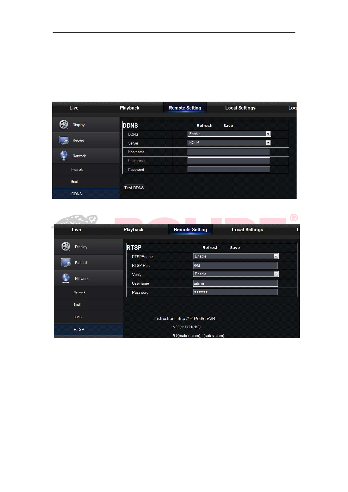
3.DDNS: After user applies for DDNS service, you could enable <DDNS> function under
any one network type mode (Static, DHCP and PPPoE). And you may remotely visit the
NVR through domain name (http://domain name: Web port No.). When visiting NVR by
using DDNS, user should make sure port and current IP can be normally connected in
public network. Details settings, including server address, host, user, and password,
should be consistent with NVR local setting.
4.RTSP: Set user name and password to view video by PC software VLC.
59
Page 65
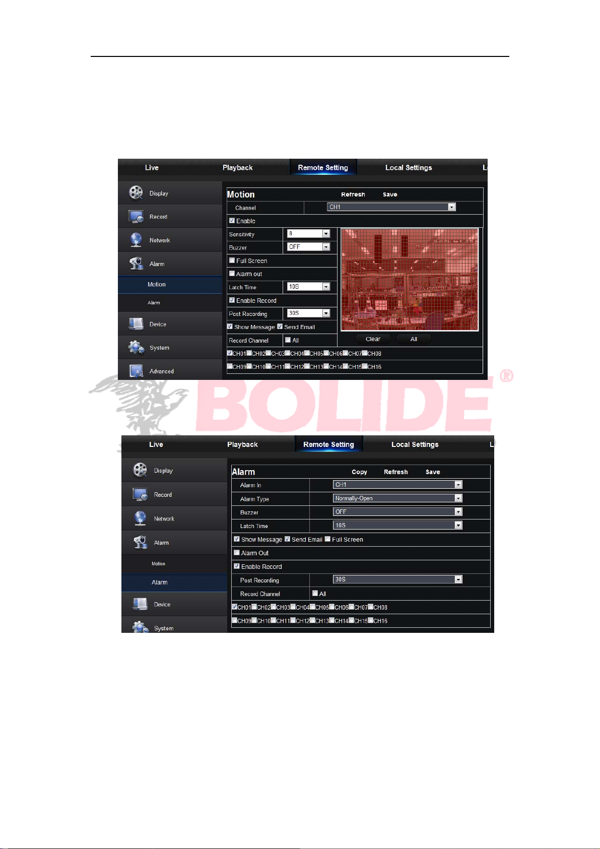
5.3.3.4 Alarm
Alarm setting includes Motion Detection and I/O Alarm Parameters.
1. Motion Detection: Configure Sensitivity, Alarm out, Alarm Record and Alarm Capture,
etc. Detailed setting should be c onsi stent with NVR local setting.
2. I/O alarm setting (If available): Set parameters for I/O Alarm, Alarm Out, Alarm
Record, Send Email, etc. Detailed setting should be consistent with NVR local setting .
60
Page 66
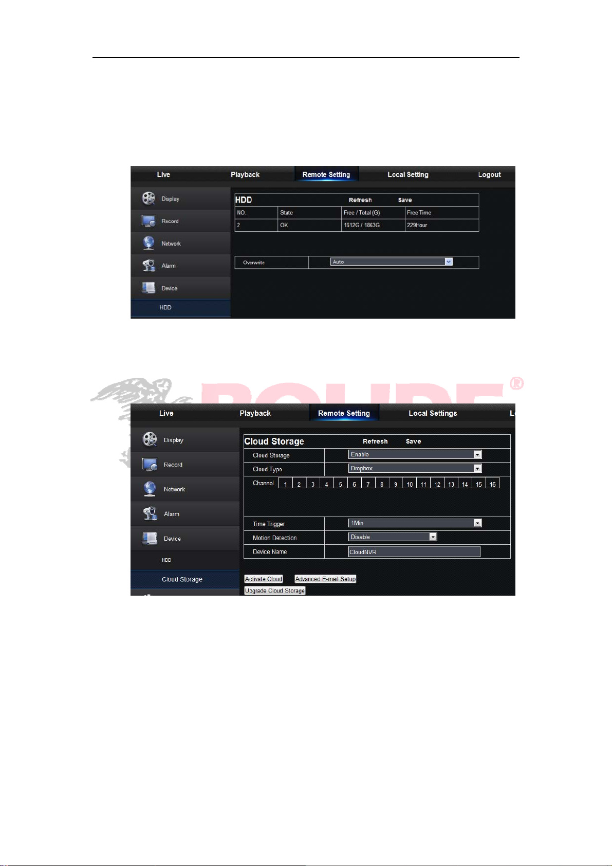
5.3.3.5 Device
Click <Device> to unfold its sub-options: HDD
HDD
User may check HDD status of NVR and overwritten time. Detail setting should be
consistent with NVR local setting.
Cloud storage
Cloud Space (Network HDD). It can upload the NVR periodically captured pictures and
motion detection captured pictures to Dropbox.
61
Page 67
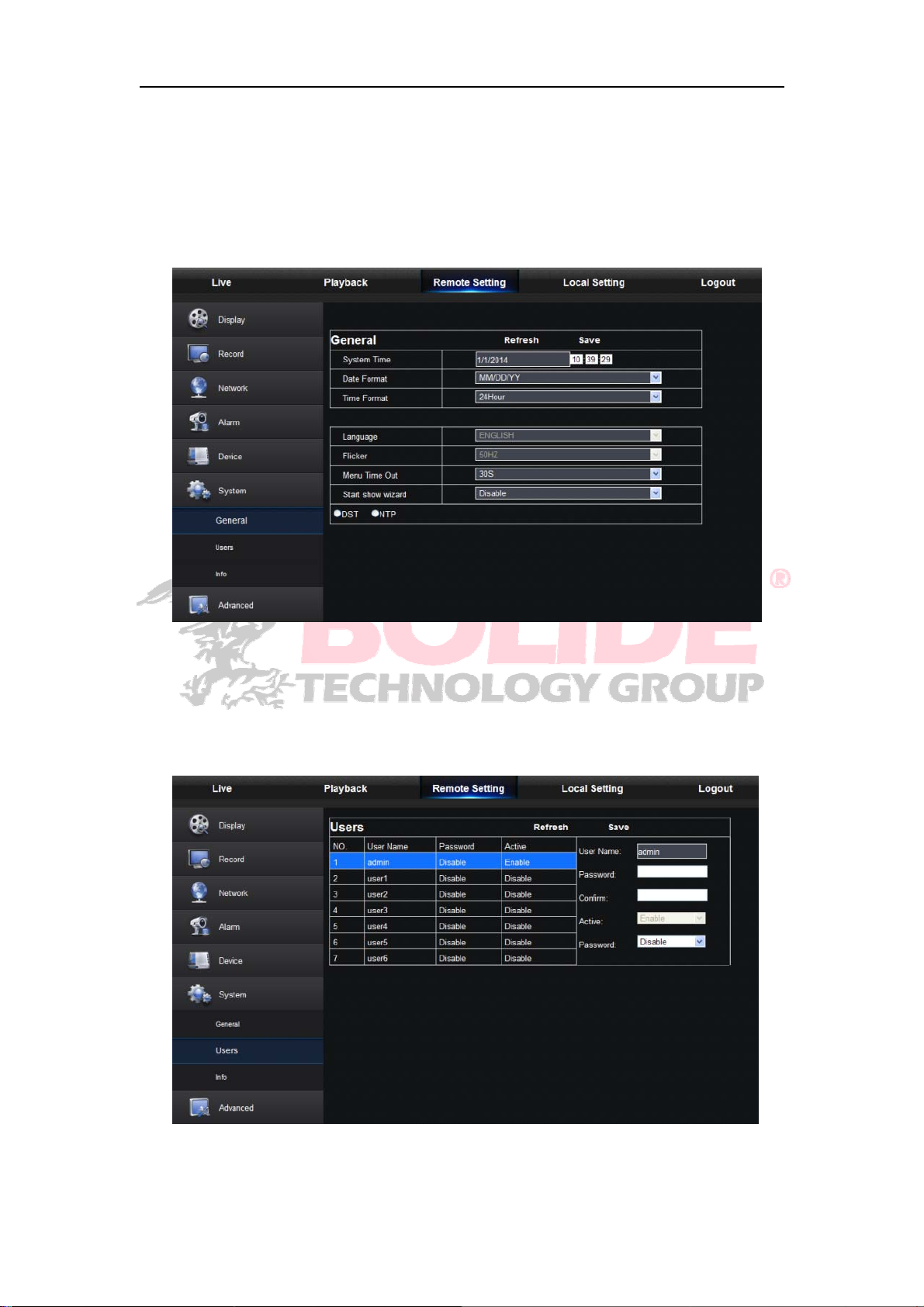
5.3.3.6 System
Click <System> option to unfold its sub-options: General, Users and information.
1. General
User may check NVR language and video system and set system time, date/time
format, menu display time, DST and NTP parameters. Detailed setting should be
consistent with NVR local setting.
2. Users
User may configure user name and password. Detailed setting should be consistent with
NVR local setting.
62
Page 68
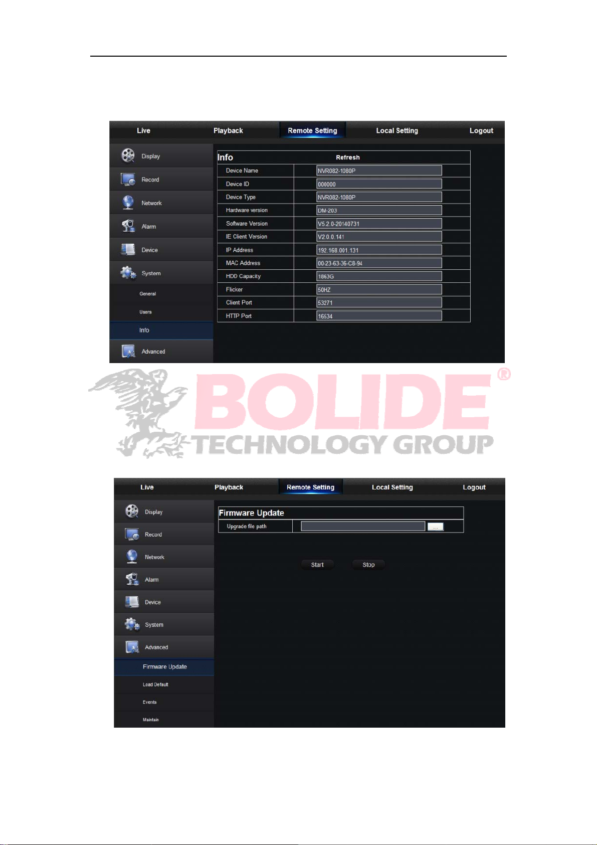
3. Information
User may search device name, device number, device type, MAC address, software
version, IE version and hardware version of NVR.
5.3.3.7 Advanced
Click Advance to unfold its sub-options: Firmware Update, Load default, Events and
Maintain.
1. Firmware Update
User may remotely update NVR system.
63
Page 69
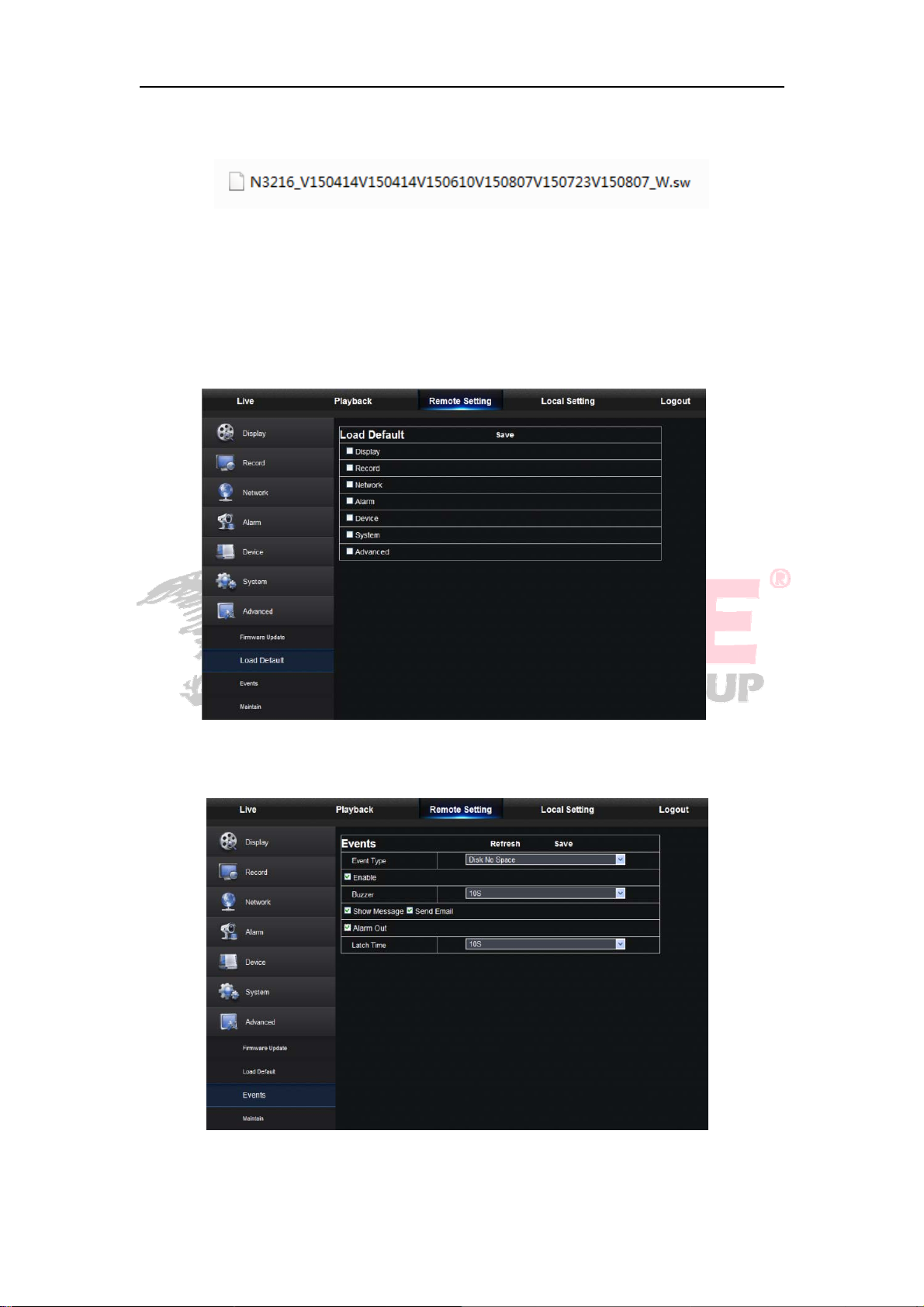
Updating procedure:
r
Firstly, select the update file path. The file format is .sw.
Secondly, click “Start” to start updating. The updating progress can be seen on the screen.
2. Load Default
User may remotely restore default parameters of NVR, with same setting method as that
of NVR.
3. Events
Use
may configure Event Type, Buzzer, Send Email, Show Message and other
parameters. Detailed setting should be consistent with NVR local setting.
64
Page 70
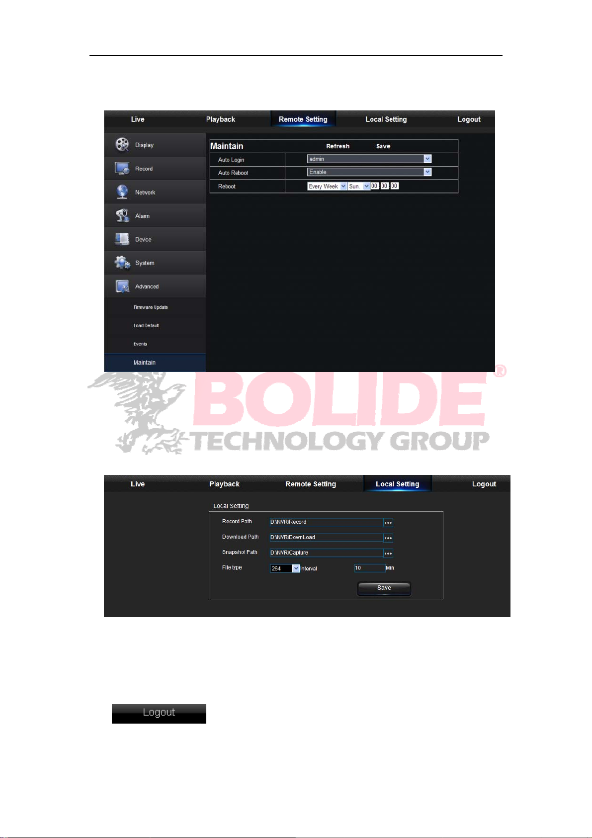
4. Maintain
Allow you remotely set auto maintain time for NVR. Detailed setting should be consistent
with NVR local setting.
5.3.4 Local Setting
User may set Record Path (save Live record and Playback clip file), Download Path for
remote file, Snapshot Path for captured pictures, Interval for switching record files
(Packaging time), and File type (H264 and AVI).
5.3.5 Logout
Click to log out and return to the Login interface.
65
Page 71

Chapter 6 Appendix
6.1 Troubleshooting
1. Q: What can I do if the system does not detect the HDD?
A: Check if the power supply system is properly connected and data cord and power
cables are securely connected, and if something wrong with the HDD interface. Or
you may check if your HDD is supported by referring to the specifications or
descriptions.
2. Q: I have changed the password but forget the new password, how can I access the
system?
A: If you forget system password, please consult with our technical personnel. We
strongly suggest user to set password easy to be remembered and relatively safe. If
you have safety requirement, please do not set very simply password, such as
000000.
3. Q: We see abnormal video signal or even no video signal by connecting the NVR and
camera together. Power supply for both devices is OK. What is wrong?
A: Check network cable at NVR side to see if the cable is firmly connected and if it is
worn out and needs to be replaced.
4. Q: How to prevent NVR from being influenced by heat?
A: The NVR needs to dissipate heat while it is running. Please place the NVR in a
place with good air circulation and away from heat sources to ensure stability and life
of the NVR.
5. Q: The remote controller doesn’t work while the monitor screen is OK and panel keys
are functional. Why?
A: Operate again by aiming the remote controller at the IR receiver on front panel. If it
still doesn’t work, please check if the batteries in the remote controller are dying. If
not, c heck if the remote controller is broken.
6. Q: I want to take out HDD from my PC and install it in NVR. Can it work?
A: All HDDs supported by the system can be used. But remember, once NVR runs,
the data on your HDD will be lost.
7. Q: Can I playback while recording?
A: Yes. The system supports the function of playing while recording.
8. Q: Can I clear some records on HDD of NVR?
A: In consideration of the file security, you may not clear part of records. If you want to
remove all the records, you can format HDD.
9. Q: Why can’t I log in NVR client?
A: Please check if the network connection settings are correct and RJ-45 port is with
good contact. And check if your account and password are correctly input.
10. Q: Why can’t I find any records during playback?
A: Please check if the data line connection for HDD is OK and system time is
properly adjusted. Try a few times and restart. If it still doesn’t work, check if the
HDD is broken.
11. Q: Why doesn’t dynamic detection work?
A: Please check if the motion detection alarm setting at IPC side is correct and if the
sensitivity is set too low.
66
Page 72

12. Q: Why doesn’t alarm work?
A: Please check if the alarm setting, alarm connection and alarm input signals are
correct.
13. Q: Why does buzzer keep alarming?
A: Please check the alarm setting, check if motion detection function is enabled and
object motion is detected all the time and if I/O alarm is set as Always Off. Besides,
refer to corresponding HDD alarm setting.
14. Q: Why can’t I stop recording by pressing “STOP” button or click “Stop Recording” in
context menu?
A: Pressing Stop button can only stop manual record. If you want to stop Scheduled
recording in certain time quantum, please change the setting to No Record. To stop
Startup recording, please change record mode to scheduled recording or manual
recording. Then you may stop recording by the prescribed methods. And another
way of stopping recording is to set channel in record setting as Off.
6.2 Usage Maintenance
1. To shut down NVR, please firstly shut down the system and then turn off the power.
Do not turn off the power directly or HDD data will be lost or damaged.
2. Please keep NVR away from heat sources or places.
3. Clean the internal dust regularly. Make sure the good ventilation of NVR so as to
ensure the good heat dissipation.
4. Please do not hot plugging cables at ports, or the ports may be damaged.
5. Please check the HDD cable and data cable regularly to see if they are ageing.
6. Please prevent the audio and video signals of NVR from being intervened by other
electronic devices, and prevent the HDD from being damaged by static electricity and
induced voltage.
7. If the network cable is frequently plugged, it is suggested to replace connecting line
regularly, or the input signal may be unstable.
8. This is A class product. it maybe bring wireless interference in life. Under this situation,
it need user to make measures.
67
Page 73
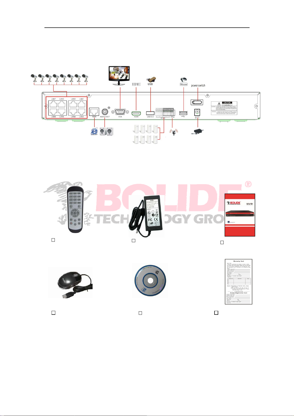
6.3 System Connection Diagram
r
A
r
r
NVR
7.2 Accessories
6.4 Accessories (Goods in kind prevail)
Remote Controlle
USB Mouse CD Warranty Card
Powe
(Goodinkindprevail)
dapte
UserManual
68
Page 74

69707172737475
Page 75

Page 76

Page 77
Page 78

Page 79

Page 80

The material in this document is the intellectual property of our
departmen t .
No part of this manual may be reproduced, copied, translated,
transmitted, or published in any form or by any means without our
department prior written permission.
Our products are under continual improvement and we rese rve the right to
make changes without notice. But no guarante e is given as to the correctne s s
of its contents.
We do not undertake any responsibility for the harms cause by using our
product.
The model of the produc ts in the user's manual on ly for reco gniti on, but
these names also perhaps are belong to other company's registered
tra d emark or the copy ri ght.
The product picture may differ from the actual product, only for your
reference. The accessories will probably be different according to the
differ ent selling areas. For details of accessor ies, p lease refer to your local
distri butor.
Copyright reserved
 Loading...