

Page 1
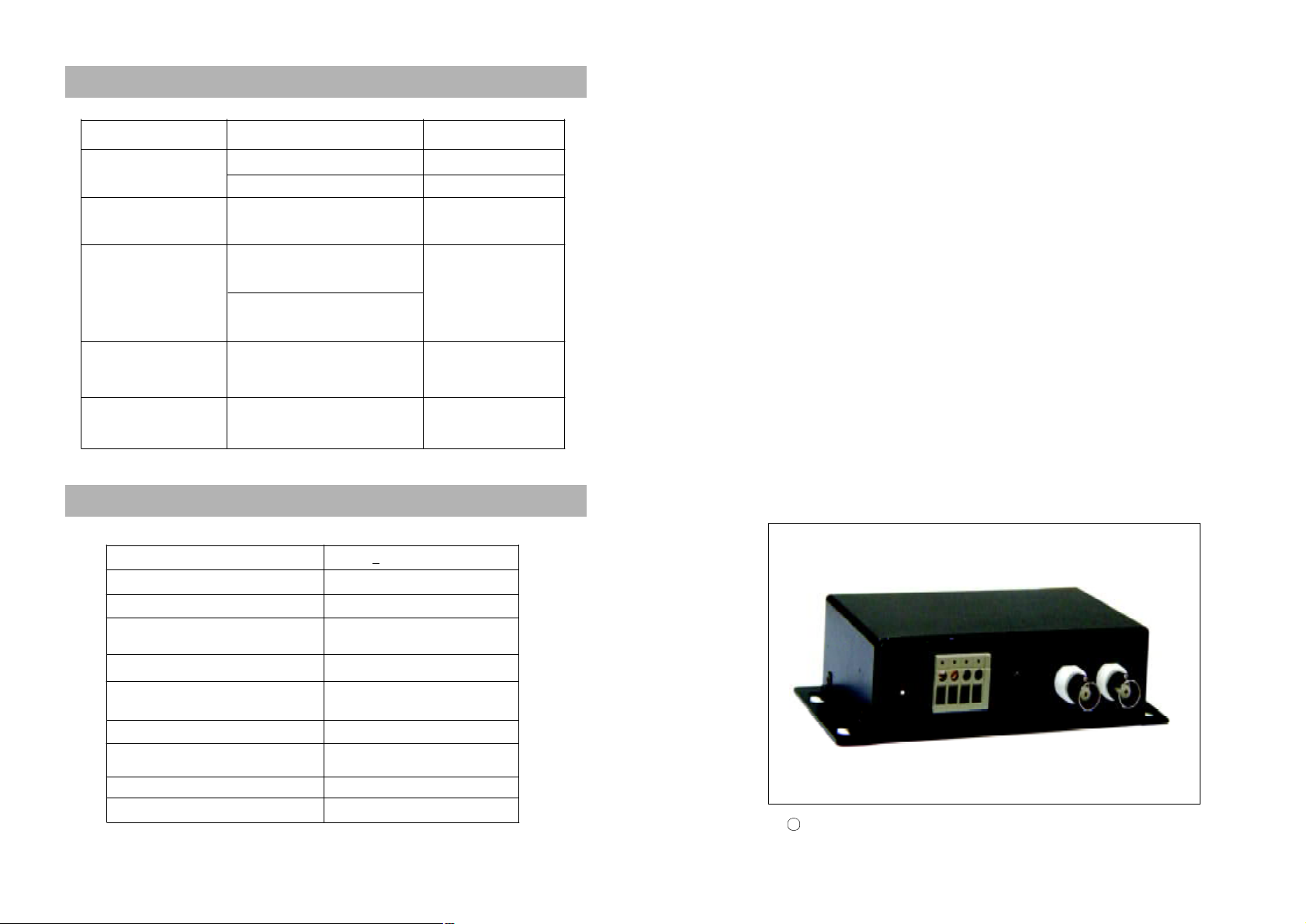
4 Trouble Shooting
Problem Possible Cause Solution
Power ON/ Receiving
Red LED OFF.
Power ON, Red LED ON,
Green LED OFF, Domes
no action.
Red LED flash and
Green LED ON,
Domes no action.
Both Red and green LED
ON, but Domes no
action.
Power ON, both Red /
Green LED flash, and
Domes no action.
Failure of Power supply. Re-connect properly.
Power Supply broke. Replace with good one.
Wrong Controlling Cable
connection.
The Receiving Protocol is not in
accordance with Transmitting
Protocol from Matrix or Keyboard.
Receiving Baud rate is not in
accordance with the transmitting
Baud rate from Coaxial converter.
Wrongly connecting with Video
Cables¡¡or no video on Domes.
( Domes’ problem)
Wrongly address setting or
Dome with problems.
5 Specification
Supply Voltage DC 9V + 20%
Power ≤1W
Weight180 g
Receiving Controlling Mode
Receiving Baud Rate(RS485/ RS232)2400/4800/9600/19200 BPS
Receiving Baud Rate
(MANCHESTER/BI-PHASE)
Transmitting Mode Coaxial Video
Farthest Transmitting Distance
(0.5mm twisted pair cable)
Environmental Temperature -10℃ ~ + 50℃
Dimensions 143 x 67.5 x 34.5(mm)
RS485/RS422/Manchester/
BI-PHASE
32KBPS
300m
Re-connect Correctly.
Reset and power ON
again.
Re-connect cables and
resolve the Dome’s
problems.
Reset and resolve the
Dome’s problems.
User Manual
One-Channel Coaxial Converter
Ⅰ
Before use the product, please read this manual carefully.
-7-
Page 2
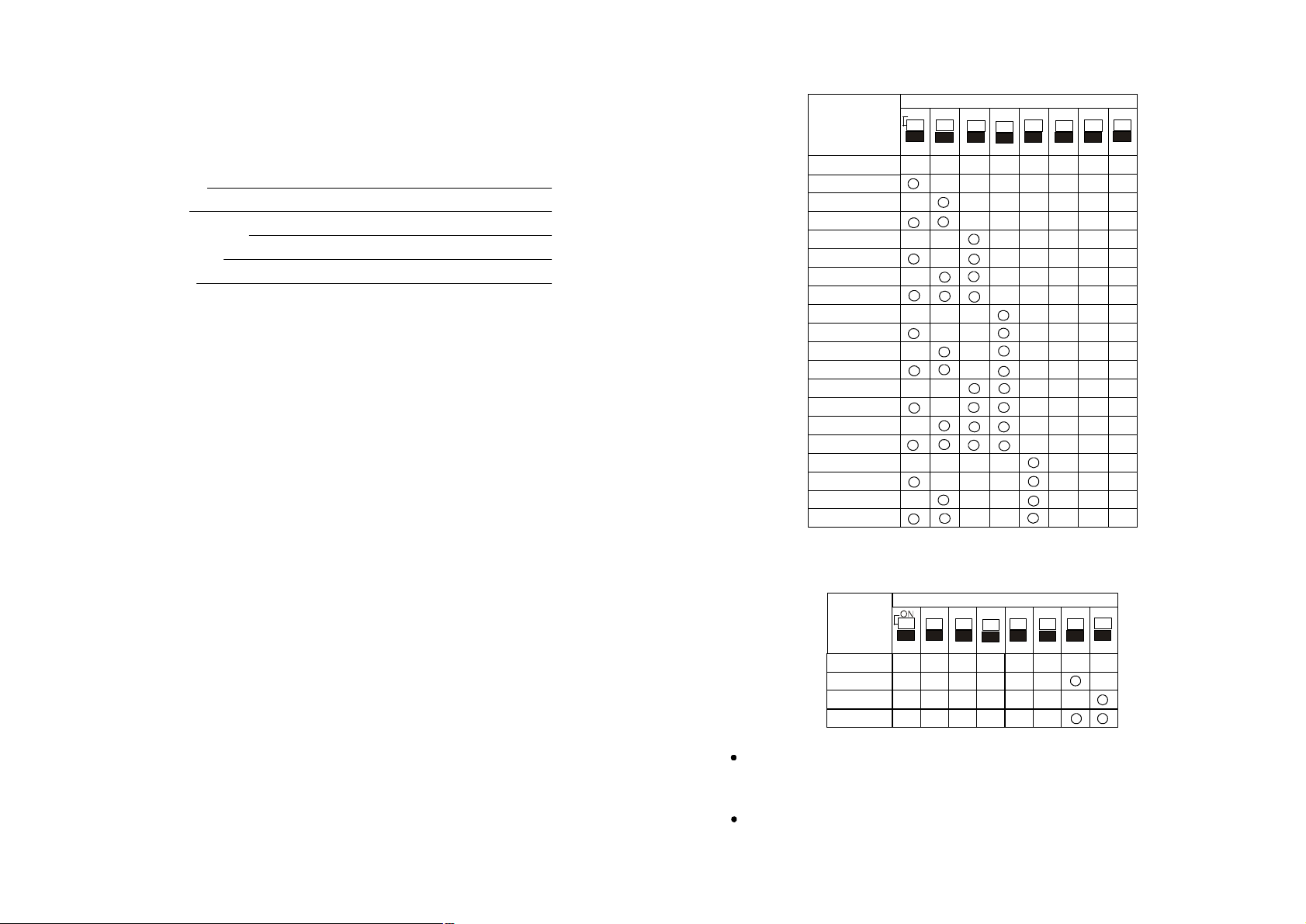
2. Protocol Setting (SW2)
1 23 4 5 6 7 8
1 2 3 4 5 6 7 8
1 2 3 4 5 6 7 8
Baud Rate
Switch number
Contents
1. Main Features
2. Installation
3. DIP Switches Setting
4. Trouble shooting
5. Specification
Protocol
FACTORY
2
2
5
7
7
VCL
PELCO_P
PELCO_D
MONYLX
VICON
DIAMOND
KALATEL_304
HUNDA
LILIN
SANTACHI
RESERVE
UNIVISION_V1
UNIVISION_V2
PHILIPS
AD
ADT
PANASONIC
KDEC300
PHILIPS_1
ONON
Switch number
-1-
3. Baud Rate Setting(SW2)
2400bps
4800bps
9600bps
19200bps
Baud rate setting is only applied to interface RS485/RS422; While Manchester / Bi-Phase
code have been chosen, ignoring any status of Dip Switch No7 or No8, no matter they are
ON or OFF.
Any of re-set by changing the DIP switches setting will not be effective unless power ON
again.
-6-
Page 3
Picture 1
3 DIP Switcher Setting
1 23 4 5 6 7 8
1 23 4 5 6 7 8
1 2 3 4 5 6 7 8
1 2 3 4 5 6 7 8
77
227
228
229
230
231
232
233
234
235
236
237
238
239
240
241
242
243
244
245
246
247
248
249
250
251
252
253
254
255
Switch number
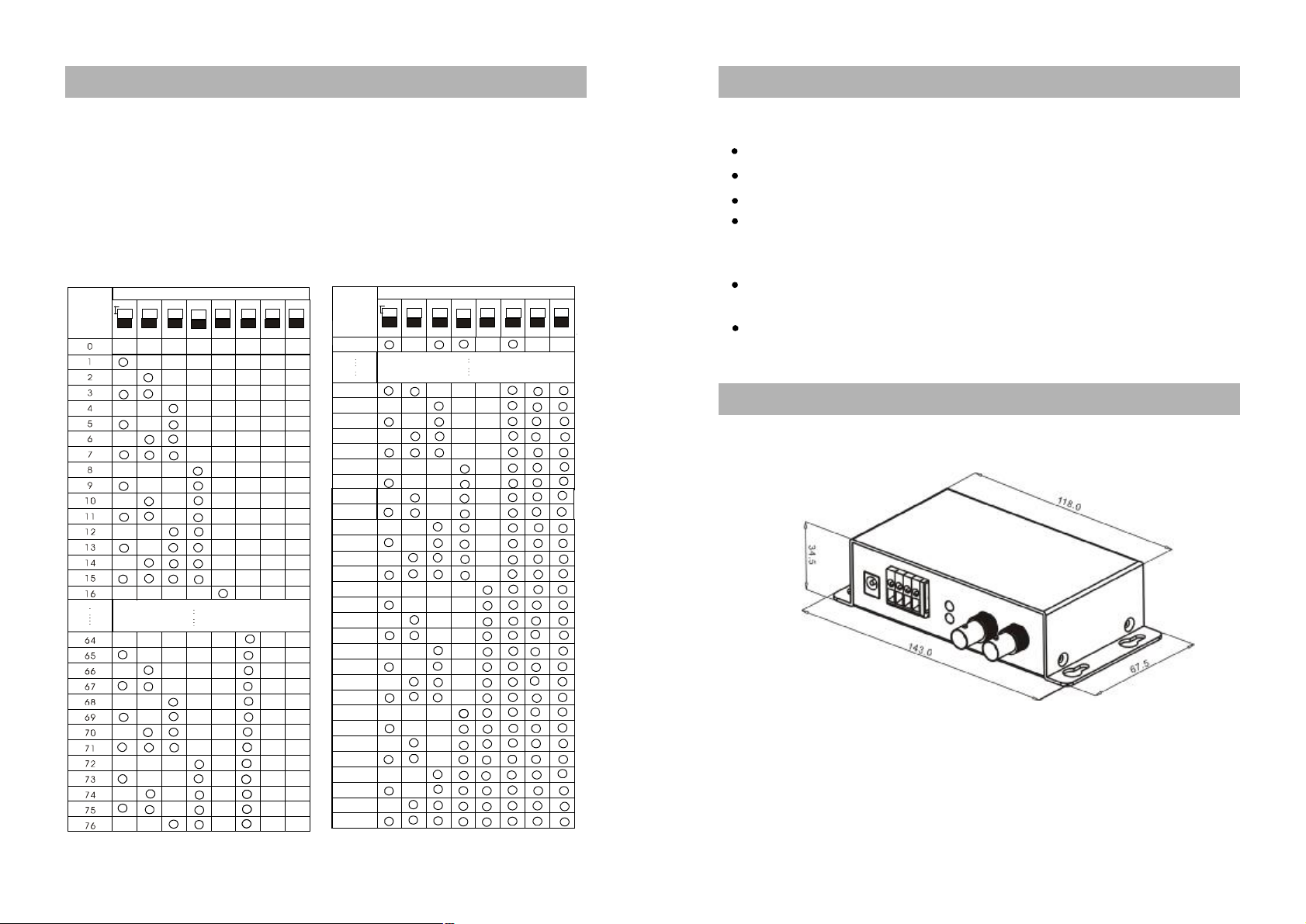
Controlling ID should be set through DIP switcher 1(SW1) (see chart SW1 below, No.1 to No.
254 to be selected as needed; 0: indicates “Testing address”; and No.255 means “Broadcasting
address”);
Protocol and baud rate should be set through DIP switcher 2(SW2), Bit 1 ~Bit 6 for setting
protocol; Bit7~Bit8 for setting baud rate as instruction. (Round mark of below chart indicates the
relative bits of DIP switcher is ON)
1. ID Setting(SW1)
Switch number
ONIDON
ID
ONIDON
ID
1 Main Features
Receiving Interface: built-in RS485/RS422 , Manchester, BI-Phase Code.
Transmitting output. (B N C )
With power supply / receiving red LED and signal transmitting green LED.
Multi-protocol options are available by setting DIP switches such as: Pelco-d, Pelco-p,
Molynx, Vicon, Lilin, Diamond, Kalatel, Hunda, Panasonic, Vcl, Univision, Philips, American
dynamics, Santachi, Kdec300,as well as the one created by manufacturer.
With four options of communication baud rates: 2400bps, 4800bps, 9600bps, 19200bps
when interface is RS485 or RS422.
With 120 Ω jumper in receiving interface.
2 Installation
1. Dimensions (mm)
-2--5-
Page 4
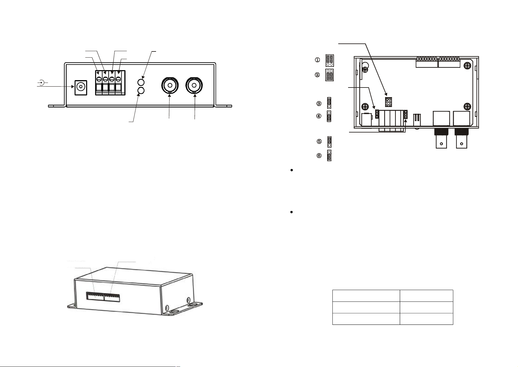
2. Front Panel with Ports
JP8
JP7
JP6
Manchester, BI-Phase
SW2(Protocol/Baud Rate)
Picture 3
Transmitting Signal LED (Green)
Picture 2
4)
4. Jumper Setting ( Inside Box)
B
A
C
D
1)
1) Power: DC+9V
-
+
Power/Receiving Signal LED (Red)
2) Video Input
3) Video Output
1) Power: DC: +9 Voltage:
2) Video Input: Connect to Video output from Speed Dome.
3) Video Output: Connect to Monitor or Matrix .
4) Controlling Cables Input: ( See picture2)
A: W/TX+: Connect to Manchester code, Bi-phase controller output or RS422 Controller RX+;
B: B/TX-: Connect to Manchester code, Bi-phase controller output or RS422 Controller RX-;
C: 485+/RX+: Connect to RS485 controller or RS422 controller TX+;
D: 485-/RX-: Connect to RS485 controller or RS422 controller TX-.
3. Rear Panel
SW1(ID Address)
and RS422 120resistorΩ
TX+/TX-
B/W
120resistor(Manchester,
Ω
Bi-Phase and RS422)
ON
OFF
120resistor(RS485/RS422)Ω
ON
OFF
Picture 4
Controlling cables connect to input A and B when communication signal are MANCHESTER
/ BI-PHASE Code or RS422(TX+,TX-), respectively Jumper 8 should be set as following
(See picture2 and 4):
a. As ① indicating while connecting RS422(TX+, TX-);
b. As② indicating while joining MANCHESTER/BI-PHASE code( B, W)
If controlling bus is located in 50 meters further, the 120 Ω Jumpers of Coaxial converter
should be switching ON. Therefore, if more than one Coaxial converter being linked, the
120Ω Jumper of the farthest one should be switching ON leaving all others OFF, details
indicated as below:
a. While joining RS422 (TX+, TX-) and MANCHESTER/BI-PHASE, 120Ω Jumper JP7
should be set as ③ and ④of Picture 4 indicated. .
b. While joining RS485, RS422(RX+, RX-), 120ΩJumper JP6 should be set as⑤and ⑥
of Picture 4 indicated.
-3-
5. Accessories
DC9V Power Spply 1 pc
User Manual 1 set
Warranty Card 1 pc
-4-
 Loading...