

Page 1
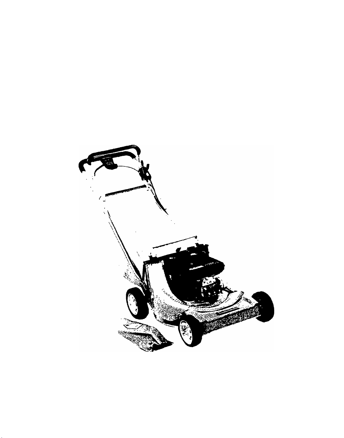
21" Self-Propelled Rotary Mower
Operating Manual
Model No. TMO-37478A
Montgomeiy Ward
Page 2

INDEX
Slope Gauge.................................................................3
Contents of Hardware Pack..........................................4
Rules for Safe Operation..............................................5
Assembly
Controls.......................................................................10
Operation....................................................................11
Adjustments................................................................13
Lubrication..................................................................14
Maintenance...............................................................14
Off-Season Storage....................................................17
Illustrated Parts.....................................................18, 21
Repair Parts Lists
Trouble Shooting Chart
Parts Information
NOTICE: A data plate with the model number and serial numbers of your unit is located on the top rear
of the deck. Record these numbers in the spaces provided on the back cover of this guide.
......................................................................
................................................
.............................................
.........................................
19-21
Back Cover
6
22
Dear Customer,
So often throughout the year we are all in a
rush to meet our daily obligations.
However, we at Montgomery Ward are tak
ing a quick moment out to sa/. , ,
"Thank you for your business."
Sincerely,
MONTGOMERY WARD
INSTRUCTIONS GIVEN WITH THIS SYM
BOL ARE FOR PERSONAL SAFETY. BE
A
SURE TO FOLLOW THEM.
BEFORE YOU CALL SERVICE
Check Spark Plug Wire
• Firmly attached?
• Wire terminal clean?
Check Crankcase Oil Level
• Overfilled/underfilled?
Check Fuel Tank
• Fuel in tank?
• Fuel dirty or stale?
• Fuel shut-off valve closed?
• If tank has been empty for a tong period,
fill tank completely.
Check Air Cleaner
• Clean?
• Choke plate stuck?
• Governor spring free to move?
Check under Blade Housing (Disconnect Spark Plug First)
• Blade obstructed or bent?
Check Starting Instructions
• Read instruction manuals and labels for specific
instructions.
WARNING: This unit is equipped with an internal combustion engine and should not be used on or near any unim
proved forest-covered, brush-covered or grass-covered land unless the engine's exhaust system is equipped with
a spark arrester meeting applicable local or state laws (if any). If a spark arrester is used, it should be maintained
in effective working order by the operator.
In the State of California the above is required by law (Section 4442 of the California Public Resources Code).
Other states may have similar laws. Federal laws apply on federal lands. A spark arrester for the muffler is available
through your nearest engine authorized service center.
Page 3
-------------------------------------------------------------------------------------------Cut Along This Line--------------------------------------------------------------------------------------------------
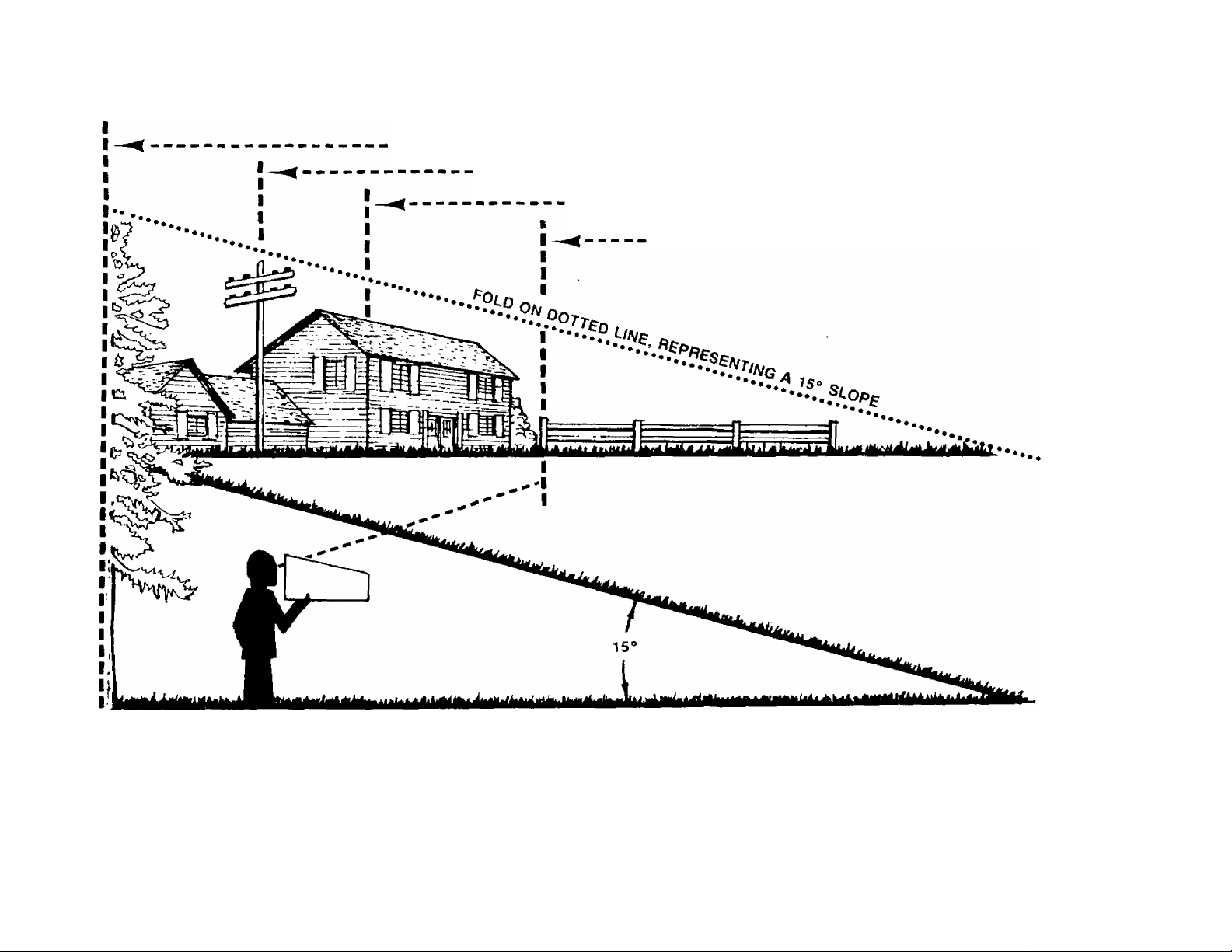
USE THIS SHEET AS A GUIDE TO DETERMINE SLOPES WHERE YOU MAY NOT OPERATE SAFELY.
SIGHT AND HOLD THIS LEVEL WITH A VERTICAL TREE
A POWER POLE
A CORNER OF A BUILDING
7s
*o
5’
tu
c/>
D)
CD
■o
0)
o
(b
(0
d)
CP
ar
<D
CO
n
OR A FENCE POST
AC WARNING ^
Do not mow on inclines with a slope in excess of 15 degrees (a rise of approximately 2Vz feet every 10 feet). A
riding mower could overturn and cause serious in|ury. If operating a walk-behind mower on such a slope, it is
extremely difficult to maintain your footing and you could slip, resulting in serious injury.
Operate RIDING mowers up and down slopes, never across the face of slopes.
Operate WALK-BEHIND mowers across the face of slopes, never up and down slopes.
c
c
(t)
—T
"♦l
o
3
o
(D
o
Page 4
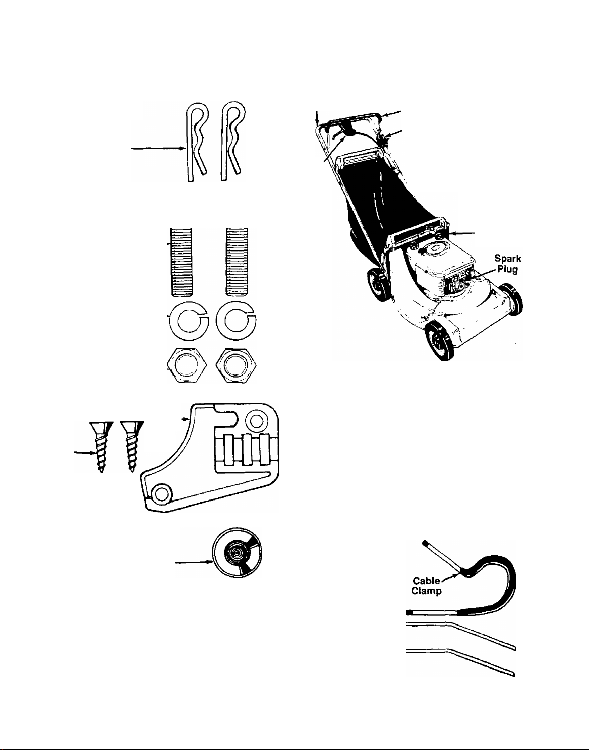
CONTENTS OF HARDWARE PACK
Remove this sheet from your owner’s manual and lay the hardware on the illustration for identification purposes.
After assembly, keep the Slope Gauge which is on the reverse side of this sheet for future use.
(Hardware pack may contain extra items which are not used on your unit.)
ATTACHfNG THE
LOWER HANDLE
Hairpin
Clips
ATTACHING THE
UPPER HANDLE
Curved Head-
Bolts
Split Washers-
5/16" I.D.
Hex Nuts
5/16-18 Thread.
ATTACHING THE DRIVE CLUTCH CONTROL
CABLE
Plastic-
Phillips
Head
Screws
Cap
Upper
Handle
Drive
Clutch
Housing
PARTS INFORMATION
ASSEMBLY OF GRASS CATCHER
(Upper Bag Support
Is Not Shown)
Blade Brake/Clutch
Control Handle
-Throttle Control
^_^Lower Handle
Housing
Catcher
Panel
o
c
>
o
3
(Q
W
ATTACHING THE BLADE
BRAKE/CLUTCH CABLE
SECURING THE CABLES
r
u
M
I I i I I I I
0
INCHES
I I
Push Cap
Truss Machine-
Self-Tapping Screws
Q[ FINAL
ASSEMBLY
Hub Caps are
Not Shown
Cable Ties
I i I I I I I
Page 5

▲
IMPORTANT
RULES FOR SAFE OPERATION
THIS SYMBOL POINTS OUT IMPORTANT SAFETY INSTRUCTIONS WHICH, IF NOT FOLLOWED, COULD ENDANGER THE PERSONAL SAFETY
ANO/OR PROPERTY OF YOURSELF AND OTHERS. READ AND FOLLOW ALL INSTRUCTIONS IN THIS MANUAL BEFORE ATTEMPTING
TO OPERATE YOUR LAWN MOWER, FAILURE TO COMPLY WITH THESE INSTRUCTIONS MAY RESULT IN PERSONAL INJURY, WHEN
YOU SEE THIS SYMBOL-
A HEED ITS WARNING.
A
A
A
Ai
Your lawn mower was built to be operated according to the rules for sate operation in this manual. As
with any type of power equipment, carelessness or error on the part of the operator can result in serious
injury. t( you violate any of these rules, you may cause serious injury Id yourself or others.
TRAINING
1. Read this owner's manual carefully in its entirety before attempt
ing to assemble or operate this machine. Be completely familiar
with the controls and the proper use of this machine before
operatirrg li. Keep this manual in a safe place lor future and regular
reference and for ordering repiacement parts.
2. Your rotary mower is a precision piece of power equipment, nrrt
a plaything. Therefore, exercise extreme caution at ail times.
3. Never allow cnildren to operate a power mower. Only persons well
acquainted with these rules of safe operation should be allowed
to use your mower,
4. Keep the area of operation clear of all persons, particularly small
children and pets. Stop engine when they are in the vicinity of
your mower to help prevent blade contact or thrown object in
jury. Although the area of operation should be completely cleared
of loreign objects, an object may have been overlooked and could
be accidently thrown by the mower in any direction and cause
serious personal injury to the operator or any others allowed in
the area.
PREPARATION
1. Thoroughly inspect the area where the equipment is to be used.
Remove all stones, sticks, wire, bones and other foreign obiects
which could be picked up and thrown by the mower in any direc
tion and cause serious personal injury to the operator or any others
allowed in ihc-area.
2. Always wear safety glasses or eye shields during operation or while
performing an adjustment or repair, to protect eyes from foreign
objects that may be thrown from the machine m any direction.
3. Wear sturdy, rough-soled work shoes and close-fitting slacks and
shirts to avoid entanglement in the moving pans. Never operate
a unit in bare feet, sandals, or sneakers.
4. Check the fuel before starting the engine. Gasoline is an extreme
ly flammable fuel. Do not fill the gasoline tank indoors, while the
engine is running, or until engine has been allowed to cool for
two minutes after running. Replace gasoline cap securely and wipe
ofi any spilled gasoline before starting the engine as it may cause
a fire or explosion.
5. Disengage the self-propelled mechanism or drive clutch on units
so equipped before starting the engine.
6. The blade control handle is a safety device. Never attempt to bypass
its operation. Doing so makes the safety device inoperative and
may result in personal injury through contact with the rotating
blade. The blade control handle must operate easily in both
directions.
7. Never attempt to make a wheel or cutting height adjustment while
the engine is running.
8. Never operate the equipment in wet grass. Always be sure of your
footing, A slip and fall can cause serious personal injury. Keep
a firm hold on the handle and walk, never run. Mow only in daylight
or in good artificia! light.
DANGER
9. For your safety, use the slope gauge included as part of this manual
to measure sfopes before operating this unit on a sloped or hilly
area. If the slope is greater than IS*’ as shown on the slope gauge,
do not operate this unit on that area or serious injury could result.
OPERATION
1. Do not change the engine governor settings or overspeed the
A
A
engine. Excessive engine speeds are dangerous.
2. Do not put hands or leet near or under rotating parts. Keep clear
of the discharge opening at all times as the rotating blade can
cause injury.
3. Stop the blade when crossing gravel drives, walks or roads.
4. After striking a foreign object, stop the engine, remove the wire
from the spark plug, and thoroughly inspect the mower for any
damage. Repair the damage before restarting and operating the
mower.
5. It the equipment should start to vibrate abnormally, stop the engine
and check immediately for the cause. Vibration is generally a warn
ing of trouble.
Shut the engine off and wait until the blade comes to a complete
6.
stop before removing the grass catcher or unctogging the chute.
I he cutting blade continues to rotate for a few seconds after the
engine is shut off. Never place any part of the body in the blade
area until you are sure the blade has stopped rotating.
Before cleaning, repairing or inspecting, таке certain the blade
and all moving parts have stopped. Disconnect the spark plug wire,
and keep the wire away from the spark plug to prevent accidental
starting.
Do not run the engine indoors.
Mow across the face of slopes, never up-and-down. Exercise ex
treme caution when changing direction on slopes. Do not mow
excessively steep slopes. Always be sure of your footing. A slip
and fall can cause serious personal injury.
Never operate mower without proper guards, plates or other safety
10
protective devices in place
11. Do not operate this mower with the chute door open, unless the
complete grass catcher is properly mounted on the mower.
MAINTENANCE AND STORAGE
1. Check the blade and engine mounting bolts at frequent intervals
for proper tightness
2. Keep all nuts, bolts, and screws tight to be sure the equipment
is in safe working condition.
3. Never store the equipment with gasoline in the tank inside of a
building where fumes may reach an open flame or spark. Allow
the engine to cool before storing in any enclosure.
4. To reduce fire hazard, keep the engine free of grass, leaves, or
excessive grease,
5 Check the grass catcher bag frequently for wear or deterioration.
For safety protection, replace only with new bag meeting original
equipment specifications.
Page 6
Rules for Safe Operation (Continued)
BLADE BRAKE/CLUTCH MAINTENANCE
NOTE:
Any required repair work on the blade brake/clutch should be
performed by an authorized service dealer. If you cannot locate an
authorized service dealer, contact the manufacturer.
1. The blade brake/clutch hand control is a safety device. Never
attempt to bypass its operation.
inoperative and may result in personal injury through contact with
the rotating blade. This hand control must operate freely in both
directions.
2.
Striking a solid object can cause damage to the blade brake/clutch
or to the engine crankshaft. Extensive vibration of the mower during
operation is an indication of damage and the unit should be
promptly inspected and repaired.
IMPORTANT: This unit is shipped WITHOUT GASOLINE or OIL. After assembly, service engine with
NOTE: Reference to right or left hand side of the mower is observed from the operating posi
Doing so makes the safety device
gasoline and oil as instructed in the separate engine manual packed with your unit.
tion. Refer to parts identification illustration on page 4 for location of parts when assem
bling the mower.
ASSEMBLY INSTRUCTIONS
3. A leak in the lower engine crankshaft oil seal could expose the
blade brake/clutch friction pads to excess oil resulting in blade
or brake slippage, which could increase the stopping time of the
blade. Oil collection on the floor beneath the mower dunng storage
may be an indication of an oil seal leak. The unit should be checked
by an authorized service dealer.
4, Periodically inspect the inner control cable in the area where it
attaches to the hand control. If the cable becomes frayed, it could
cause the blade brake/clutch to operate improperly. Also, be careful
to avoid pinching the blade brake/clutch control cable when stor
ing the handle.
Tools Required for Assembly
(1) Pair of Pliers
(1) Phillips Head Screwdriver
(1) 1/2" Wrench*
(1) 5/16" Wrench or Nutdriver*
(1) 7/16" Wrench*
*Or one 6" Adjustable Wrench.
UNPACKING
1. Remove the lawn mower from the carton by open
ing the top flaps and lifting the unit out. Be careful
of the staples. Make certain all parts and literature
have been removed from the carton before the car
ton is discarded.
2. Disconnect and ground the spark plug wire against
the engine. Check beneath the deck for any card
board packaging. Remove if present.
3. Stretch out all control cables and place on the floor.
Be careful not to bend or kink the cables at any
time during assembly.
4. Remove page four from this manual and lay the
contents of the hardware pack on the illustration
for identification.
ATTACHING THE LOWER HANDLE (Hardware A)
1. For shipping purposes your mower is set with the
wheels in the lowest cutting height position. Raise
the mower to the highest setting for assembly of
lower handle.
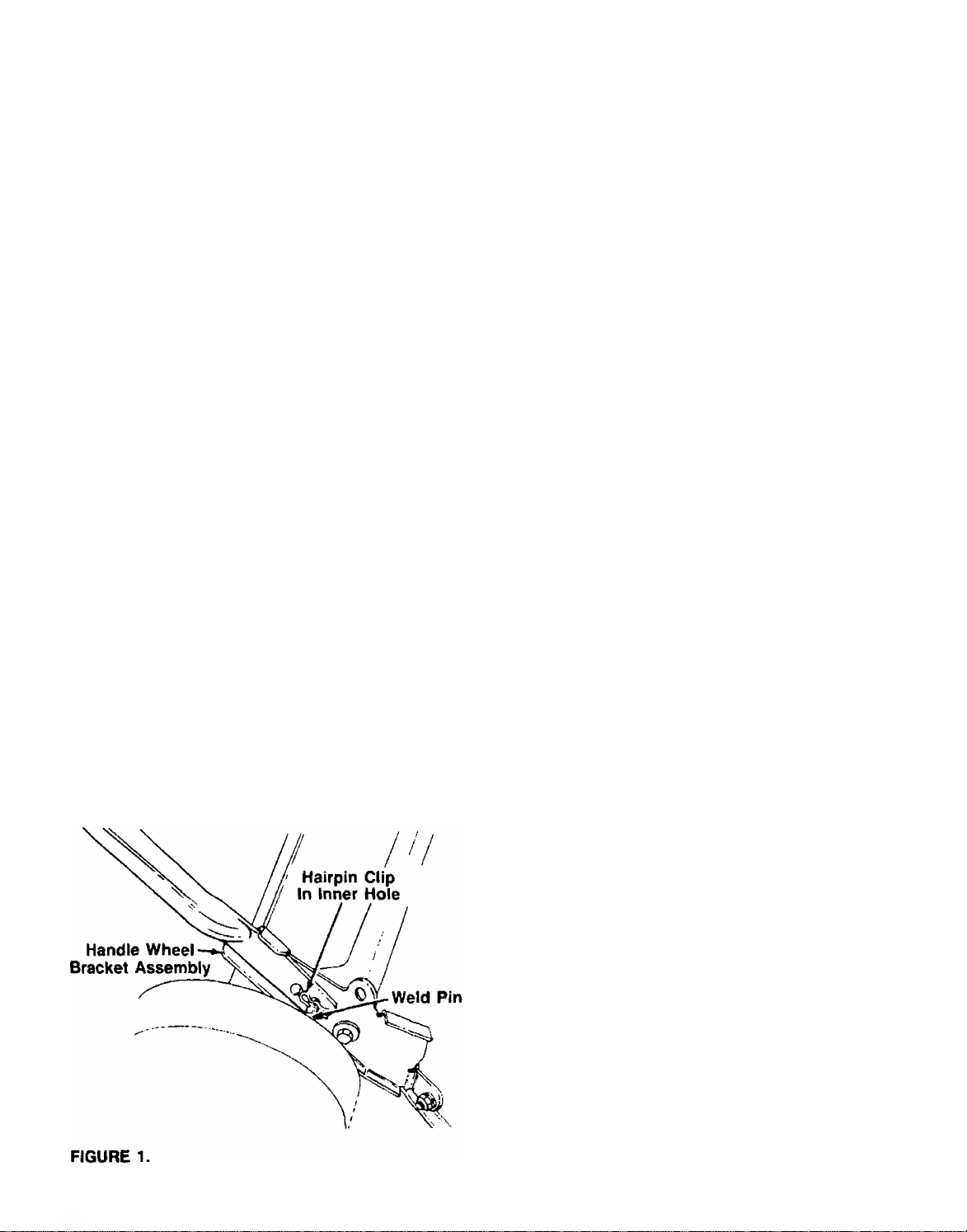
2. Attach the lower handle by placing the bottom
holes in the lower handle over the weld pins on the
handle wheel bracket assemblies on the rear of the
deck. Make certain the instruction label on the
lower handle can be read from the operating
position.
—3. Using a pair of pliers, squeeze one leg of the lower
handle against the handle wheel bracket assembly.
Insert the hairpin clip into the inner hole on the
weld pin. See figure 1. Repeat on other side.
Page 7
split Washer
Hex Nut
FIGURE 2.
FIGURE 3.
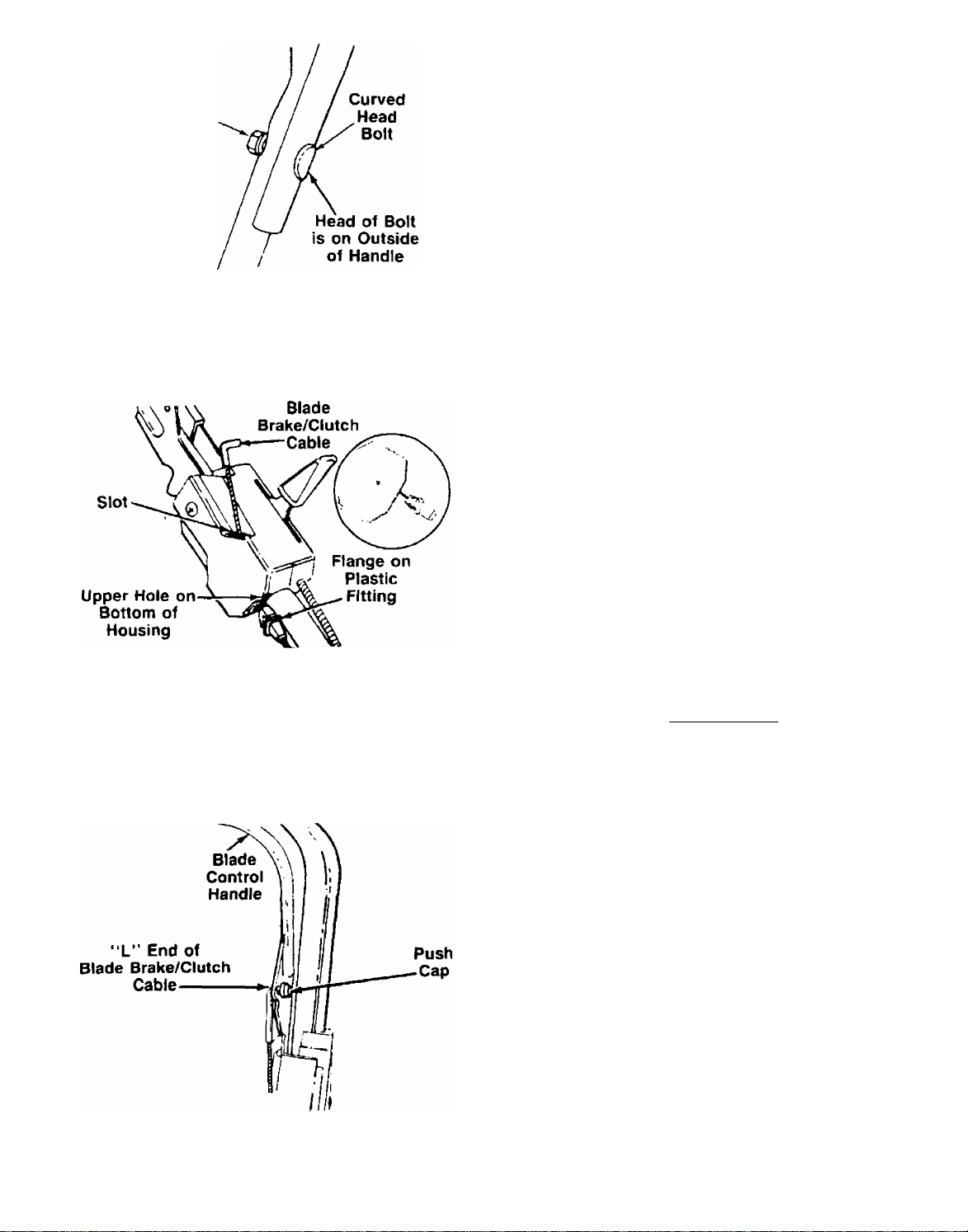
ATTACHING THE UPPER HANDLE (Hardware B)
Place upper handle in position over lower handle. The
label on the throttle control housing and the control
lever must be facing up. Secure upper handle with two
curved head bolts, split washers and hex nuts. See
■figure 2.
ATTACHING THE BLADE BRAKE/CLUTCH CABLE
(Hardware O)
The blade brake/clutch cable is the cable which has
an “L” fitting on the loose end. and is attached to the
blade brake/clutch underneath the deck.
1. Route the blade brake/clutch cable to the outside
of the catcher panel and height adjustment lever,
and under the lower handle. Place end of cable into
the upper hole on the bottom of the control hous
ing, and through the slot on the side of the hous
ing as shown. The angle of the plastic flange must
------
be positioned downward as shown in figure 3. Be
careful not to bend or kink the cable at any time,
2. Push the plastic flange until it locks into the con
trol housing.
i WARNjNG ^
A
The cable must be assembled as
shown for proper blade brake/clutch
operation.
FIGURE 4.
3. Insert the “L” end of the blade brake/clutch cable
into the hole in the blade brake/clutch control han
dle, from the inside to the outside as shown in
—figure 4. Hold the end of the cable, and press push
cap on by hand.
Page 8
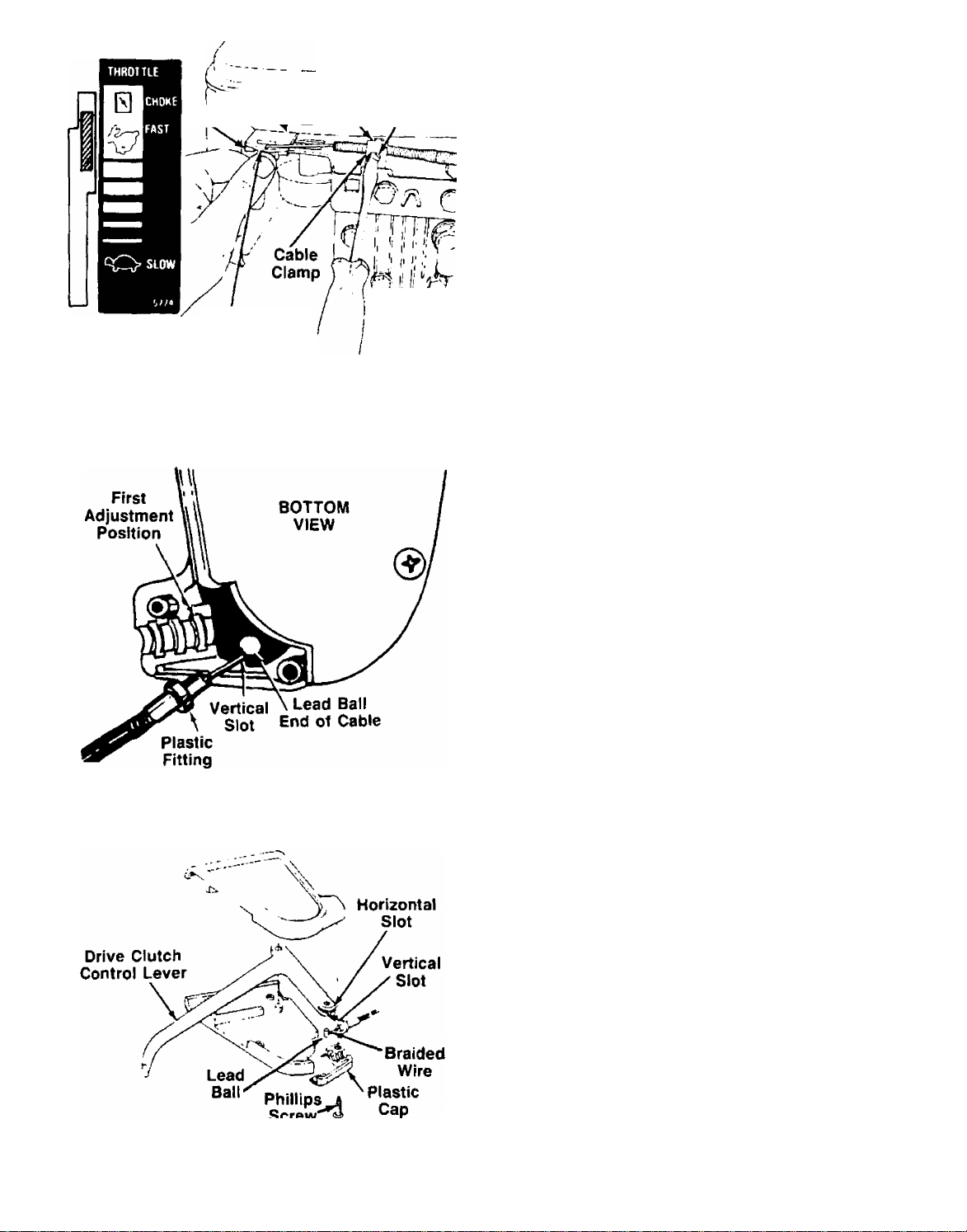
FIGURE 5.
Rush^^^r Slotv Screw
Control Lever
on Engine
U J I r IJ1
l-i'i, P
ATTACHING THE THROTTLE CABLE
1. Push the throttle control lever on the handle all the
way forward to CHOKE, then back it off two
------
“clicks” (approximately 5/16"). See figure 5.
2. The throttle control cable is attached to the upper
handle. Route the throttle control cable to the out
side of the height adjustment lever and catcher
panel. Hook the ”2” end of the throttle control
cable into the hole in the control lever on the
engine. See figure 5.
3. Using a 5/16" wrench or nutdriver, remove the
screw on the cable clamp shown in figure 5. Slip
the control cable under the clamp. Replace the
screw (cable should be above the screw), but do
not tighten screw (cable must still move freely
beneath the clamp). Make certain the tab on the
cable clamp is seated into the slot on the engine.
4. Push the control lever on the engine as far toward
the outside of the engine as it will go. The edge
of the control lever should be flush with the bracket
on the engine. See figure 5. Hold the control lever
in this position as you tighten the screw on the
cable clamp to secure the throttle cable.
5. Loosen the screw on the clamp on the side of the
engine. Slip the cable casing under the clannp to
secure the cable away from the muffler Be
careful not to bend or kink the cable. Tighten the
screw.
FIGURE 6.
figure 7.
ATTACHING THE DRIVE CLUTCH CONTROL
CABLE (Hardware C)
■The drive clutch control cable is attached to the deck.
Attach the cable to the lever in the clutch control hous
ing, located in the middle of the upper handle, as
follows.
1. Place the lead ball end of the cable into the fitting
provided in the end of the clutch control lever. Slip
the braided wire into the vertical slot as shown in
figure 6.
2. Slide the braided wire around in the horizontal slot.
See figure 7.
3. Place the plastic fitting on the control cable Into
the first adjustment position in the clutch control
housing. See figure 6.
4. Secure the plastic cap to the clutch control hous
ing using the two Phillips head screws. See figure
------
7.
i WARNING 1
A
Drive clutch adjustment must be
checked before the unit is operated,
as described in the operation sec
tion.
Page 9

FIGURE 8.
Grass Catcher
Handle—
Truss Machine
Self-Tapping ,
Screw (
FIGURE 9.
}\
/
Plastic
Channels
■ Upper Bag
Support
Brackets
SECURING THE CABLES (Hardware E)
Secure all cables to the grass catcher panel and lower
handle as toltows.
A. Open the cable clamp provided in your hardware
pack, and slip the cables inside. Remove the up
per hex nut and lock washer from the side of the
catcher panel. Attach cable clamp as shown in
-----
figure 9A. Secure with lock washer and hex nut.
B. Place the height adjustment lever in the lowest posi
tion. Insert posts on cable ties into holes provided
on the left side of lower handle, one near the top
and one near the bottom of the handle. The holes
may be on either the inside or outside of the han
dle. See figure 9B.
C. Secure the cables with the cable ties, making cer
tain to take the slack out of the cables so they do
not contact the wheel. See figure 9C.
D. Trim excess ends of cable ties.
ASSEMBLY OF GRASS CATCHER (Hardware F)
1. Place bag over frame (black plastic side is the bot
tom of bag). Handle on frame goes to the top of
bag. Brackets hook toward the front. See figure 9.
2. Secure bag to frame by slipping plastic channels
-------on bag over frame. See figure 9.
3. Insert the upper bag support into the pocket on the
rear of the bag. Place grass catcher handle on top
of grass catcher support as shown in figure 9. The
handle should hook toward the rear of the bag as
shown in figure 9. Secure with two truss machine
self-tapping screws.
TO ATTACH BAG TO MOWER
FIGURE 10.
A
WARNING
DO NOT operate the mower unless the
complete grass catcher or side chute
deflector is properly mounted on the
mower.
1. Hook the handle on the rear of the grass catcher
over the lower handle of the mower. See figure
—10A.
2. Hold the chute door on the catcher panel open as
shown in figure 10B.
3. Slide the frame of the grass catcher down into the
channels on the catcher panel. The top portion of
the frame goes over the catcher panel.
4. Secure the grass catcher by turning the locking
lever to the locked position as shown in figure IOC.
To remove the grass catcher, turn the locking lever to
the unlocked position, unhook the rear handle and lift
the grass catcher straight up.
Page 10

TO CONVERT MOWER TO SIDE DISCHARGE
To convert your mower to a side discharge unit, remove
only the grass bag and top discharge chute, and
assemble the side chute deflector. It is not necessary
to remove the catcher panel and brackets.
To remove the top discharge chute, proceed as follows.
•See figures 11 and 12.
1. Remove the wing nuts on the side of the deck.
2. Lift up on the front edge of the discharge chute,
then slide it toward the side, removing it from the
bolts in the side ot the deck.
3. Attach the side chute deflector by first placing it
over the rear bolt in the side of the deck, then over
the front bolt and sliding it into position, with
shoulder bolt on deck in notch on deflector. Secure
with wing nuts.
•FINAL ASSEMBLY OF MOWER (Hardware G)
1. Attach hub caps to the wheels by lining up the hub
caps with the wheels. Push to lock in position.
2. Make certain all nuts and bolts are tightened
securely.
CONTROLS
THROTTLE CONTROL
The throttle is located on the left side of handle. It con
trols engine speed. See figure 13.
DRIVE CLUTCH CONTROL
Squeezing the drive clutch control engages the drive
mechanism to the rear wheels. Releasing the clutch
control stops the rear wheels from driving. Release the
drive clutch control to slow down when negotiating an
obstacle, making a turn or stopping. See figure 13.
BLADE BRAKE/CLUTCH CONTROL
WARNING
THIS CONTRCX MECHANISM IS A
SAFETY DEVICE NEVER ATTEMPT
TO BYPASS ITS OPERATIONS
The blade brake/clutch control is located on the upper
handle of the mower. The blade brake/clutch handle
engages and disengages the blade.
To engage the blade, pul! the side release lever away
from the unit. See figure 13. Pull the blade brake/clutch
control handle against the upper handle. Release side
lever.
Release the blade brake/clutch control handle to stop
the blade from turning.
10
Page 11

OPERATION
DO NOT OPERATE MOWER UNLESS
THIS GUARD OR ENTIRE GRASS-
CATCHER IS IN ITS PROPER PLACE.
FIGURE 14.
Keep hands and feet away from the chute area on cut
ting deck. See figure 14.
NOTE
For shipping purposes your mower
is set with the wheels in a low cut
ting height position. For best re
sults raise the cutting position un
til it is determined which height is
best for your lawn. See cutting
height adjustment section.
BEFORE STARTING
Before each use, check for proper drive clutch opera
tion by performing the following before starting the
engine;
With the drive clutch control released, push mower for
ward. tt should move freely. Pull mower backward. It
should move freely.
If it does not and the rear wheels tend to lock up, the
clutch may not be releasing completely. Do not start
the engine until corrections have been made. Check
the control cable for severe bend, kinks and binding,
or grass build-up in the pulley grove. Correct and ad
just as required.
TO START ENGINE
WARNING
A i
When starting the unit for the first
time, face the mower against a solid
object such as a wall, fence, etc.
Start the unit, and if it shows any
signs of motion with the drive clutch
control disengaged, shut the engine
off immediately. Check the position
of the drive clutch control cable.
The plastic fitting must be assem
bled in the first adjustment position
inside the housing, all the way to the
right, as shown in figure 6.
GAS AND OIL FILL-UP
Service the engine with gasoline and oil as instructed
in the separate engine manual packed with your
mower. Read instructions carefully.
NOTE
Your unit has been shipped without oil;
however, a small amount of oil may be
present from the factory. Do not overfill.
A
Never fill fuel tank indoors, with en
gine running or until the engine has
been allowed to cool for at least two
minutes after running.
1. Attach spark plug wire to spark plug. Make certain
the metal loop on the end of the spark plug wire
{inside the rubber boot) is fastened securely over
the metal lip on the spark plug. See figure 15.
Metal Loop
on Spark
Plug Wire
Rubber Boot
FIGURE 15.
2. The fuel shut-off valve is located beneath the fuel
tank. The fuel shut-off valve should be in the open
position. See figure 16. Open fuel shut-off valve
if it is closed. It may be necessary to remove the
discharge chute.
11
Page 12

FIGURE 16.
3. Move throttle control lever to CHOKE position.
NOTE
A warm engine may not require choking.
4. With the blade brake/clutch handle released,
crank engine by pulling recoil starter with a quick
firm pull. Do not pull out so far that rope stops with
a jerk as this will cause rope failure. Do not allow
rope and handle to snap back into place.
5. After engine starts, move throttle control to desired
engine speed.
TO STOP ENGINE
1. Move throttle control lever to STOP position.
2. Disconnect spark plug wire from spark plug and
ground against the engine to prevent accidental
starting while equipment is unattended.
NOTE
If a warm engine falters or stalls when
attempting to engage the blade, refer
to Carburetor Adjustment Section of
this owner’s manual.
3. Release the blade brake/clutch control handle to
stop the blade from turning.
NOTE
Always release the blade brake/clutch control han
dle before stopping the engine. If the engine begins
to stall, release the blade brake/clutch control handle
immediately.
Should the engine stall with the blade brake/clutch con
trol in the operating position (control handle not re
leased), difficulty may be encountered in pulling the
starter rope to restart the engine. Proceed as follows.
1. Disconnect the spark plug wire from the spark
plug.
2. Move the throttle lever to STOP position.
3. Hold the blade brake/clutch control in the engaged
position.
4. While holding the blade brake/clutch control han
dle in this position, pull the starter rope.
5. As the starter rope is being pulled, release the
blade brake/clutch control handle.
The starter rope should now operate correctly. Recon
nect the spark plug wire for normal operation.
NOTE
If any problems are encountered, refer
to the Trouble Shooting Chart on page
22.
i WARNING 1
A
Never operate your unit without
either the side chute deflector or entire
top discharge chute and catcher panel
assembly in place.
TO ENGAGE THE BLADE
1. Start engine as instructed previously. Allow the
engine to warm up for one minute before at
tempting to engage the blade.
2. To engage the blade, pull the side release lever
away from the unit. Pull the blade brake/clutch con
trol handle down against the upper handle.
Release the side lever. See figure 13.
USING YOUR ROTARY MOWER
WARNING
A
DO NOT operate the mower with the
chute door open unless the com
plete grass catcher is properly
mounted on the mower.
Be sure that lawn is clear of stones, sticks, wire, or other
objects which could damage lawn mower or engine.
Such objects could be accidently thrown by the mower
in any direction and cause serious personal injury to
the operator and others.
Operate a new engine at intermediate speeds and light
load for the first few hours as you would a new
automotive engine.
For the best results, do not cut wet grass because it
tends to stick to the underside of the mower, prevent
ing proper discharge of grass clippings, and could
cause you to slip and fall. New grass, thick grass or
wet grass may require a narrower cut. Blade speed
should be adjusted to the condition of the lawn.
12
Page 13

When using the side discharge mower, the best mow
ing pattern is one that allows the clippings to discharge
towards the uncut part of the lawn. This permits recut
ting of the clippings to further pulverize them. When
cutting high weeds, discharge towards cut portion, then
recut at right angles to first direction.
For best results, cut off one-third or less of the total
length of the grass. Lawn should be cut in the fall as
long as there is growth.
This mower is designed to be operated at full throttle
to give you the best cut and do the most effective job
of bagging the cut grass.
CUTTING HEIGHT ADJUSTMENT
The height adjustment handle is located on the left side
of the deck. The handle may be placed in one of nine
cutting height positions. Push the handle to the left and
then either forward to lower the cutting height or
backward to raise the cutting height. See figure 18.
For rough or uneven lawns, move the height adjustment
handle to a position which will give a higher cutting
height.
IMPORTANT
If you strike a foreign object, stop
the engine. Remove wire from spark
plug, thoroughly inspect the mower
for any damage, and repair the
damage before restarting and
operating the mower.
Striking a solid object can cause
damage to the blade brake/clutch or
to the engine crankshaft. Extensive
vibration of the mower during opera
tion is an indication of damage. The
unit should be promptly inspected
and repaired.
ADJUSTMENTS
Ac WARNING \
Do not at any time make any adjust
ment to lawn mower without first
stopping engine and disconnecting
spark plug wire,
Height
Adjustment
Handle
FIGURE 18.
THROTTLE
The throttle control wire assembly can be adjusted if
necessary. Loosen the screw on the cable clamp shown
in figure 5. Adjust as instructed in steps 1 and 4 of “At
taching the Throttle Control Cable’’ in Assembly In
structions.
CARBURETOR ADJUSTMENTS
DRIVE CLUTCH CONTROL ADJUSTMENT
If the unit does not self-propel with the drive clutch con
trol engaged, remove the plastic cap from beneath the
drive clutch control housing. Move the plastic fitting on
the control cable to the next adjustment position on the
left. Reassemble the plastic cap and retest. See figure
17.
II warning \
A
If any adjustments are made to the
engine white the engine is running
{e.g. carburetor), disengage all
clutches and blades. Keep clear of
alt moving parts. Be careful of
heated surfaces and muffler.
Minor carburetor adjustments may be required to
compensate for differences in fuel, temperature,
altitude and load. Refer to the separate engine manual
packed with your mower.
NOTE
If a warm engine falters or stalls
when attempting to engage the blade,
the carburetor mixture should be adjusted
1/8 turn richer (counterclockwise). See
figure 19.
13
Page 14

The carburetor should be adjusted with the air cleaner
in place and the blade control handle in the blade
disengaged position.
NOTE
A dirty air cleaner will cause an engine
to run rough. Be certain air cleaner is
clean before adjusting carburetor. Refer
to the separate engine manual.
Idle Speed
Adjusting Screw
Idle Mixture
Valve
FIGURE 19.
Discharge Chute Door Mechanism—The torsion
spring and pivot point should be lubricated periodical
ly with light oil to prevent any rust or binding. Door must
work freely.
Wheels—Lubricate the wheel bearings at least once
a season with light oil. Also, if the wheels are removed
for any reason, lubricate the surface of the axle bolt
and the inner surface of the wheel with light oil. A 4
oz. plastic bottle of light oil lubricant is available. Order
part number 737-0170. Engine oil may also be used.
Engine—Follow engine manual for lubrication in
structions.
Throttle—Periodically lubricate throttle control lever
and throttle wire assembly with a few drops of light oil
for ease of operation.
Transmission—The transmission is pre-lubricated and
sealed at the factory. It does not require checking. If
disassembled for any reason, fill with 2 ounces of
Alvania grease, part number 737-0168.
LUBRICATION
Always stop engine and disconnect
spark plug wire before cleaning,
lubricating or doing any kind of
work on lawn mower.
Blade Brake/Clutch—Lubricate the pivot points on the
blade brake/clutch handle and the cable at least once
a season with light oil. The control must operate freely
in both directions. See figure 20.
FIGURE 20.
MAINTENANCE
Ac warnÌn?
Be sure to disconnect and ground the
spark plug wire before performing any
repairs or maintenance.
NOTE
When tipping the unit, empty the fuel
tank and keep engine spark plug side
up.
TROUBLE SHOOTING
Refer to page 22 of this manual for trouble shooting
information.
CUTTING BLADE
To remove the cutting blade for sharpening or replace
ment, remove the two hex nuts and lock washers which
hold the blade to the blade brake/clutch. Protect hands
by using heavy gloves or a rag to grasp the cutting
blade. See figure 21.
14
Page 15

FIGURE 21.
When sharpening the blade, follow the original angle
of grind as a guide. It is extremely important that each
cutting edge receives an equal amount of grinding to
prevent an unbalanced blade. An unbalanced blade will
cause excessive vibration when rotating at high speeds,
may cause damage to the mower and could break,
causing personal injury.
The blade can be tested for balance by balancing it on
a round shaft screwdriver. Remove metal from the
heavy side until it balances evenly.
When replacing the blade, be sure to install the blade
with the side of the blade marked “Bottom" {or with
part number) facing the ground when the mower is in
the operating position.
Blade Mounting Torque
Make certain that the center bolt which secures the
blade brake/clutch and the two hex nuts which secure
the blade are tightened to between 350 inch pounds
(minimum) and 600 inch pounds (maximum).
To insure safe operation of your unit, all nuts and bolts
must be checked periodically for correct tightness.
DECK
The underside of mower deck should be cleaned after
each period of use as grass clippings, leaves, dirt and
other matter will accumulate. This accumulation of
grass clippings, etc., is undesirable as it will invite rust
and corrosion and may cause an uneven discharge of
grass clippings at the next cutting.
The deck may be cleaned by tilting the mower and
scraping clean with a suitable tool or by washing with
a stream of water from a garden hose.
NOTE
Do not direct the stream of water at a
hot engine as damage to the engine
may result.
ENGINE
Refer to the separate engine manual for all engine
maintenance instructions.
Maintain engine oil as instructed in the separate
engine manual packed with your unit. Read and follow
instructions carefully.
Service air cleaner every 25 hours under norma! con
ditions. Clean every few hours under extremely dusty
conditions. Poor engine performance and flooding
usually indicates that the air cleaner should be ser
viced. To service the air cleaner, refer to the separate
engine manual packed with your unit.
The spark plug should be cleaned and the gap reset
once a season. Spark plug replacement is recom
mended at the start of each mowing season; check
engine manual for correct plug type and gap specifi
cations.
Clean the engine regularly with a cloth or brush. Keep
the cooling system (blower housing area) clean to per
mit proper air circulation which is essential to engine
performance and life. Be certain to remove all grass,
dirt and combustible debris from muffler area.
BLADE BRAKE/CLUTCH
This unit is equipped with a blade brake/clutch. If for
some reason the blade brake/clutch becomes in
operative, it is suggested that all repair work on the
blade brake/clutch should be performed by an author
ized service dealer. The unit should be inspected by
an authorized service dealer if any of the following con
ditions are noticed.
1. Frayed clutch control cable.
2. Leaking oil seal (oil collection on the floor during
mower storage).
3. Extensive vibration of the unit.
BELT REMOVAL AND REPLACEMENT
1. Disconnect the spark plug wire and ground it
against the engine.
2. Drain the fuel tank or place a piece of plastic
beneath the cap to prevent gasoline leakage.
3. First remove the grass bag, discharge chute and
catcher panel.
4. Remove the transmission belt cover by removing
three bolts. Loosen the transmission belt auard
See figure 22.
15
Page 16

Screwdriver
in Slot
FIGURE 22.
5. Tip the mower on its side, and block securely.
6. Remove the blade by removing two hex nuts and
lock washers. Refer to figure 21.
NOTE
When reassembling, tighten hex nuts to
between 350 and 600 in. lbs.
7.
Remove the inside belt guard by removing two self
tapping screws. A 3/8" wrench is required. See
figure 23.
8. Remove the center bolt as follows.
a. Insert a screwdriver into the slot provided in the
blade brake/clutch housing where the control
cable enters the housing. See figure 23.
b. Place a 5/8" wrench on the center bolt. Turn
the wrench slowly until the screwdriver catches
in a groove provided inside the clutch. The
screwdriver will now keep the clutch from turn
ing, and the center bolt and cupped washer
may be removed. Lift off lower housing.
FIGURE 23.
9. Remove belt from the engine pulley half. Remove
the belt from between the idler pulley and the belt
guard on the idler pulley bracket. See figure 24.
FIGURE 24.
IMPORTANT
Upon reassembly, be certain to tighten
center bolt to between 350 and 600 in.
lbs.
10. Push the idler to the left and remove the belt from
the transmission pulley. See figure 25.
16
Page 17

FIGURE 25.
11. Reassemble the new belt, following instructions in
reverse order.
NOTE
When reassembling the ..transmission
belt cover, be certain the transmission
belt guard is approximately 1/8" away
from the belt. Make certain to tighten
all nuts and bolts securely. If plastic
was placed under the gas cap, be
certain to remove it.
OFF-SEASON STORAGE
The following steps should be taken to prepare lawn
mower for storage.
1. Clean and lubricate mower thoroughly as de
scribed in the lubrication instructions.
2. Refer to engine manual for correct engine storage
instructions.
3. Coat mower’s cutting blade with chassis grease
to prevent rusting.
4. Store mower in a dry, clean area.
__
^ NOTE
When storing any type of power
equipment in an unventilated or
metal storage shed, care should be
taken to rustproof the equipment.
Using a light oil or silicone, coat the
equipment, especially cables and all
moving parts.
NOTE
The use of any accessory on this Rotary Mower other
than those manufactured by the mower manufacturer
is not recommended.
WARNING 1
DO NOT operate the mower with the chute door open unless the complete
A
grass catcher is properly mounted on the mower.
DO NOT operate the mower without the protective shield on the rear of
2.
the deck in place.
Under norma! usage bag material is subject to wear and should be checked
periodically. Be sure any replacement bag complies with the mower manufac
turer’s recommendations.
For replacement bags, use only factory authorized replacement bag No.
764-0216.
I
NOTE
17
Page 18

TMO-37478A
18
Page 19

TMO-37478A
PARTS LIST FOR MODEL TMO-37478A
REF.
NO.
I
1
! 54
L!i.
PART NEW nPF 1
NO.
1
720-0225 Grip (2 Req’d.) N
2 16739
3
731-0734
4
710-0796 Truss Mach. Scr. #12 x
Control Handle Ass’y,—L.H. N
Top Discharge Chute Ass’y-
DESCRIPTION
1.50" Lg.
5
732-0401
6
720-0190
7
731-0817
8 731-0524
9
731-0816 Clutch Panel Half
10
731-0528 Throttle Control Lever
11
731-0975 Hub Cap N
12
731-0607
13 714-0507
14
749-0437
15
16129 Panel Support Brkt.
16 17196
17
17095
18
710-0429
19
732-0483
Lockout Spring
Spring Lever Knob
Control Panel Half
Control Disc Pin
Lock Pin .314" Dia X 1.75"
Cotter Pin 3/32" Dia. x .75" * 66
Upper Handle—Chrome
Top Catcher Panel Ass'y.
Top Discharge Door
Hex B-Tap Scr. #10 x ,38"
Torsion Spring 70
20 747-0514 Pivot Pin
21
710-0134 Carriage Bolt ’/4-20 x .62"* 72 732-0481
22
710-0286
Truss Mach. Scr. ’/4-20 x
.5" Lg.
23
24
710-0289
738-0704
Hex Bolt ’/4-20 X .50" Lg.*
Shoulder Bolt .312" Dia. x
.18" Lg. Special
25 710-0258
Hex Bolt ’/4-20 X .62" Lg.*
26 712-0287 Hex Nut ’/4-20 Thd.*
27
736-0270
28 736-0329
29 16702
731-0802
30
31
731-0619
32
735-0639
33
712-0388
34
746-0672
35
749-0505
36 4 H.P.
764-0216 21" Top Discharge Grass Bag
38
39
14835
41 736-0204
42
17055
43 710-0352
Bell-Wash. ’/4" I.D. 78 777-5815
L-Wash. ’/4" I.D.* 79 777-5811
Front Grass Catcher Frame [
Grass Catcher Handle 1
S.P. Control Cover
Spark Plug Insulator
Wing Nut N 83
Throttle Control Wire 58" Lg.
Lower Handle—Chrome
Engine B&S 110702-0212-03
Retaining Strip 88
FI-Wash. .344" I.D. X .62"
Chain—Axle Ass’y.
Hex B-Tap Scr. ’/4" x .38" 91
Lg.
44
741-0180
Flange Ball Bearing ’/2" I.D, 93
45 710-0776 Hex AB-Tap Scr. ’A x .62"
46 747-0526
47
712-0296
48
713-0353
Upper Bag Support 1
Hex Patch L-Nut 3/8-24 Thd.
#48 Chain .500" Pitch x 30
Links
49
712-0346
50 731-0564
51 731-0672
52
726-0240 Cable Tie
53
712-0328
710-0969
Hex L-Nut ’/2-20 Thd.
Plug
Rear Flap 3.75" x 17.30" Lg. 100
Hex Nut 3/8-24 Thd. (Gr. 8)
Hex AB-Tap Scr. #12 x 1.0"
Lg.
742-0306
21" Blade
4 H.P. 21" ROTARY MOWER
part! no. 1
PART
NO.
58 1 736-0412
j
59
747-0510
60 1
710-1002
61
748-0190
62
736-0169
63
736-0119
64
16136
65
16137
710-0260 Carriage Bolt 5/16-18 x .62"*
67
710-0603
N 68 710-1007 Hex Wash. Hd. TT-Tap Scr.
N
69 712-0267 Hex Nut 5/16-18 Thd.*
720-0223
71
732-0473
1
73 736-0242 Bell-Wash. 5/16" I.D.
74 750-0526
750-0624
75
77 726-0233 Bolt Retainer Va x .50" O.D.
738-0137
80
81 748-0188
82 734-1510
712-0189
N 84 741-0486 Sleeve Bearing ’/2" I.D.
728-0171
85
14924
86
87 720-0224
722-0134
731-0883
89
N 90
736-0271
710-0875
14300
92
741-0124
94 732-0396
746-0650
95
754-0343
96
97 14304
12894
98
99 731-0520 Ball Block
710-0436
101
751-0463 Casing Clamp
102
17075CC621
103 741-0326
104 14305
N
105 10662
19
DESCRIPTtON
Beli-Wash. .46" I.D. x .88"
O.D.
Height Adj. Rod 19.42" Lg.
Hex Bolt 7/16-20 X 2.0" Lg,
(Grade 5)
Spacer .513" I.D. x .703" i
O.D. X .69" Lg.
L-Wash. 3/8" I.D.*
L-Wash. 5/16" I.D,*
R.H. Handle Wheel Brkt.
Ass’y.
L.H. Handle Wheel Brkt.
Ass’y.
Hex Wash. Hd. B-Tap Scr.
5/16-18 X .5" Lg.
3/8-16 x 1.5" Lg.
Grip
Height Adj. Lever
Extension Spring .50" O.D.
x 3.80" Lg,
Spacer .385" I.D. x .502"
O.D. x .270" Lg.
Shid. Spacer .500" Dia. x
.100"
Instruction Label
Control Label
ShId. Scr. .342" Dia. x .268"
Pawl
Wheel Ass’y. Comp.—Rear
8 x 2.0"
Flat Weld Nut ’/4-20 Thd.
Pop Rivet .156" Dia. x .379"
Cable Bracket
Grass Catcher Locking Knob
Foam Strip 1" Lg.
Panel Clip
Spring Wash. .32" I.D.
Hex Tap Scr. ’/a-20 x .75" Lg.
Clutch Blade Housing Ass'y.
Ball Brg. .669" I.D. x 1.574"
Comp. Spring .35" O.D. x
2.0" Lg.
S.P. Cable x 50" Lg.
”V”-Belt
Clutch Cone
Casing Clamp
Hex B-Tap Scr. #10 x .62"
21" Deck Ass’y.
Steel Ball .50" Dia.
Brake Cup Cone
Front Axle Ass’y.
NEW
PART
N
N
N
N
Page 20

TMO-37478A
4 H.P. 21" ROTARY MOWER
PARTS LIST FOR MODEL TMO-37478A (CONTINUED)
REF.
NO.
106
107
108
109
110
111
112
113
114
115
116
117
118
121
122
123
124
125
126
127
128
129
130
131
PART
NO.
DESCRIPTION
711-0313 Sleeve .526" I.D. x .690" 133
O.D, X .880" Lg. 135
732-0397 Ext. Spring 1.75" Lg. 136
714-0104 Intern. Cotter Pin 5/16" Dia. 137
732-0482 Extension Spring .50" O.D, 138
X 3.20" Lg.
14309
736-0221
738-0705
734-1511
Clutch Housing
Intern. L-Wash. 3/8 I.D.'
Shid. Bolt .623" Dia. x .425
Front-Wheel Ass’y. Comp.
7 x 2,0" N
731-0617
731-0618
731-0620
720-0190
710-0841
Self-Propelled Control Cover
Self-Propelled Control Cover
Control Lever
Door Grip
FI-“C’’-Sunk Hd. Tap Scr.
#10 X .75" Lg.
710-0671
Curved Carr. Bolt 5/16-18 x
1.38" Lg.
756-0504
736-0409
756-0503
736-0408
710-0618
Fixed Pulley Adapter
Serrated Washer 1.0" t.D.
Serrated Pulley Half
Wave Washer 1.005" t.D.
Flat HD Tap Scr. V4-20 x
.625" Lg.
748-0319
748-0320
746-0406
748-0318
714-0115
Flywheel
Flywheel Adapter
Control Cable—49" Lg.
Ratchet Wheel 1.62" O.D.
Cotter Pin 1/8" Dia. x 1.00"
f-g.’
NEW
PART
—
REF.
NO.
140
142
PART
NO.
16559CC621
753-0431
10622
17176
17053
710-0599
736-0326
Side Chute Deflector Ass'y.
Kit—Control Housing Comp.
Spring—Nylon
Engine Mounting Plate Cover
Chain Cover
Hex Wash. S-Tap Scr. V4-20
X .50" Lg.
FI-Wash. .510" I.D. x 1.0"
O.D.
741-0522
143
144
736-0300
Hex Flange Brg. .506" t.D.
FI-Wash. .385" I.D. x .87"
O.D.
147
148
738-0719
741-0324
Rear Shaft Ass’y, 21.94" Lg.
Hex Flange Bearing .506"
I.D. Plastic
149
736-0160 FI-Wash. .531" I.D. x .930"
O.D.
150
736-0179
FI-Wash. .531" I.D. x 1.25"
O.D,
151
741-0491 Flanged Nyliner Brg.
152
710-0751
Hex Bolt 1/4-20 x .62" Lg.
(Grade 5)
153
717-0417
Transmission Comp.
(See Breakdown)
154
16500 Hex Bearing Cup
726-0245
155
156
157
726-0135
717-0845
Push Cap
Push Cap
Blade Brake Clutch Ass’y.
Comp.
DESCRIPTION
--------
NEW
PART
N
i
'Common Hardware—May be purchased locally.
IMPORTANT; DO NOT order parts by reference
number (Ref. No.).
Part No.
8176B088-8
788-0621
777-7002
770-6474C
NOTE; Specifications subject to change without notice
or obligation.
Description
Hardware Pack
Brilliant Fire Mist Spray Paint
Montgomery Ward Plastic Logo
Operating Manual
20
Page 21

TNIO-37478A
94-
—«.M
53-
s_- ^
3Q^
29 5.
"V \ ¿,-8 ’
\,rv j ;-‘-< ,:i> . 4i-
26.
y
i"^'
6—■.>
il'rV.’""
--------
V^.5'
J \
9
« iS> \,(,
"11
'"12
25. ^
\
I
H 35
-.-.4k
23-
22-
21
20
-F ' i'"
\
19
Id V"
4 H.P. 21" ROTARY MOWER
PARTS LIST FOR MODEL TMO-37478A
REF.
NO.
PART
NO.
1
710-0106
736-0329 L-Wash. 1/4" I.D.* 23 736-0270
2
717-0418 Upper Hsg. Half 24 17052
3
713-0400
4
Hex Bolt 1/4-20 X 1.25" Lg.’ i
#48 Sprocket 7 Tooth x '/2
DESCRIPTION
NEW
PART
REF.
NO.
22
PART
NO.
741-0482
25 712-0138
Needle Brg. .375" x .31|
Bell-Wash. .265" I.D. x .75"!
Idler Brk't. Ass'y !
Hex Patch L-Nut V4-28 Thd.!
Pitch ' 26 732-0357 Extension Spring 1.12" Lg.!
736-0336
5
741-0413
6
16500 Hex Bearing Cup
7
736-0314
8
741-0479 Thrust Bearing .375" I.D. x 32 738-0607 Gear Sprocket Shaft
9
715-0152
10
717-0420
11
748-0208 Flange Bearing
12
721-0212
13
738-0708
14
15
756-0330
736-0270
16
712-0351
17
738-0440 iShId. Spacer .375" Dia. x i 42 736-0270
18
736-0344
19
738-0691
20
756-0447
Li'
Ft-Wash. 5/8" I.D. x .030
Hex Flange Brg. .631" I.D.
Thrust Wash. .382" I.D. x 1
.70" O.D.
.812" O.D.
Spring Pin Spir. 1/8" x .62"
Heavy 1 35
11 Tooth Helical Gear
Oil Seal 38
Pulley-Transmission Shaft
27 717-0419 Lower Hsg. Half
28 741-0415 Flange Bearing .566 Dia.
29
717-0422 33 Tooth Helical Gear
30 741-0414
31
721-0213
Flange Bearing .629 Dia.
Oil Seal .625 Dia.
33 736-0722 ' L-Wash. #10 I.D.
34
710-0436
736-0410
36
17058
37
17065
710-0352
39 710-0599
Hex B-Tap Scr. #10 x .62"
' Hex Washer .26" x .88"t
1 Transmission Belt Guard!
Belt Covert
, Hex B-Tap Scr. V4 x .38" Lg.f
! Hex AB-Tap Scr. Va x .50"
Fl-Pulley 5.06" O.D.t Lg.t
Bell-Wash. .265" I.D. x ,75"t
Hex L-Nut 1/4-28 Thd.f 41
40 710-0896
712-0287
Hex B-Tap Scr. V4 x .62" Lg.
Hex Nut V4-20 Thd.’!
Bell-Wash. .265" I.D. x .75"!
! -170t
! FI-Wash. .390" I.D. x 1.0"t
Shid. Bolt .375" Dia. x ,40"t
Fl-ldler Plastic 1.50" Dia.t
! 43 736-0329 i L-Wash. 1/4" I.D.*!
1 44
746-06501 S.P. Cable—50" Lg.!
; 45
! —
747-0549 :
717-04171
S.P. Belt Guard!
Transmission Comp.
----
——
tNot Part of Transmission Complete
DESCRIPTION
-------------------
— _
NEW
PART
______________
21
Page 22

Trouble Shooting Chart
Problem
1 Engine fails to start A Check fuel tank for gas
2 Hard starting or
loss of power
3 Operation erratic
Cause Remedy
B Fuel shut-off valve closed
C Spark plug lead wire discon
nected
D Throttle control lever not in
the starting position
E Faulty spark plug
F Carburetor improperly ad
justed, engine flooded
G Old stale gasoline
A Spark plug wire loose
B Carburetor improperly
adjusted
C Dirty air cleaner
A Dirt in gas tank
B Dirty air cleaner
C Water in fuel supply
D Vent in gas cap plugged
E Carburetor improperly
adjusted
A Fill tank if empty.
B Open fuel shut-off valve.
C Connect lead wire.
D Move throttle lever to start
position.
E Clean, adjust gap or replace.
F Remove spark plug, dry the
plug, crank engine with plug
removed, and throttle in off po
sition. Replace spark plug and
lead wire and resume starting
procedures.
G Drain and refill with fresh
gasoline.
A Connect and tighten spark
plug wire.
B Adjust carburetor. See separate
engine manual.
C Clean air cleaner as described
in separate engine manual.
A Remove the dirt and fill tank
with fresh gas.
B Clean air cleaner as described
in separate engine manual.
C Drain contaminated fuel and
fill tank with fresh gas.
D Clear vent or replace gas cap.
E Adjust carburetor. See
separate engine manual.
4 Occasional skip
(hesitates) at high
speed
5 Idles poorly
6 Engine overheats
7 Excessive vibration
Note: For repairs beyond the minor adjustments listed above, contact your local service dealer.
A Carburetor idle speed too
slow
B Spark plug gap too close
C Carburetor idle mixture ad
justment improperly set
A Spark plug fouled, faulty, or
gap too wide
B Carburetor improperly
adjusted
C Dirty air cleaner
A Carburetor not adjusted
properly
B Air flow restricted
C Engine oil level low
A Cutting blade loose or
unbalanced
B Bent blade
A Adjust carburetor. See
separate engine manual.
B Adjust to .030".
C Adjust carburetor. See
separate engine manual.
A Reset gap to .030" or replace
spark plug.
B Adjust carburetor. See
separate engine manual.
C Clean air cleaner as described
in separate engine manual.
A Adjust carburetor. See
separate engine manual.
B Remove blower housing and
clean as described in separate
engine manual.
C Fill crankcase with the proper oil.
A Tighten blade. Balance blade.
B Replace blade.
22
Page 23

Page 24

SERVICE NATIONWIDE
Montgomeiy Ward
HOW TO OBTAIN
REPLACEMENT PARTS AND SERVICE
The morchandise you have purchased from us has been carefully
engineered and manufactured under Montgomery Ward’s rigid quali
ty standards and should give you satisfactory and dependable opera
tion. However, like all mechanical merchandise, it may occasionally
require adjustment, replacement parts or maintenance.
Toll Free Parts Sales Center
When you need a replacement part or accessory for a major ap
pliance, home electronic item or lawn and garden product that is
not under warranty or covered by a service contract or if you need
the location of the nearest service facility, call our Parts Sales Center
toll free 1-800-323-1965.
Provide the following;
1. Model, serial number and all of the other data shown on the model
plate.
2. Also give the part number or numbers as shown in the parts list
that came with the product.
Replacement Parts wilt be made available at current prices. If re
quested, prices will be quoted in advance when not listed.
If you order parts by mail, you will pay the transportation charges
from the shipping point.
UNIT MODEL NO.
UNIT SERIAL NO.
ENGINE MODEL NO.
TYPE NO
CODE NO.
PART NO. 770-6474C (R880322)
128-176B088
___________________________________
_________
_______
PRINTED IN U.S.A.
 Loading...