

Page 1
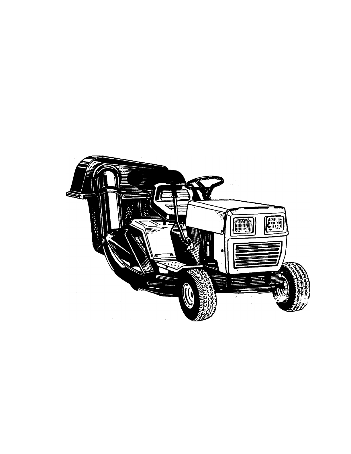
38" Lawn Tractor
Operating Manual
Model No. TMO-3394704
ll/fontgomeiy Ward
Page 2

INDEX
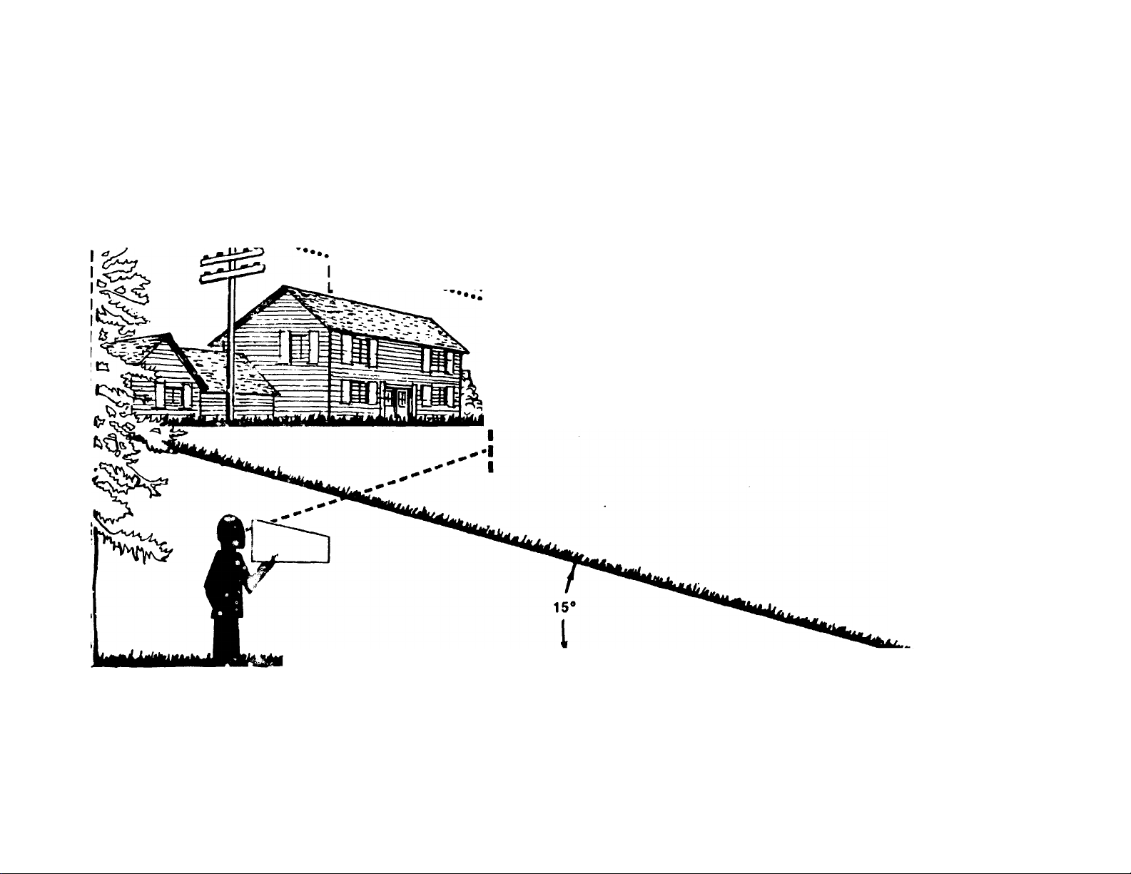
Slope Gauge
Contents of Hardware Pack
Safe Operation Practices.........................................5
Assembly Instructions
Controls
Operation
Adjustments
Lubrication............................................................14
Maintenance..........................................................14
Off-Season Storage
Trouble Shooting Guide........................
Electrical System
Illustrated Parts for Lawn Tractor
Parts Information
NOTICE: A data plate with the model numbers and serial numbers of your unit is located on the frame, under the seat. Record these numbers in the spaces provided on the back cover of this guide.
...........................................................
.....................................
........
....................................6
.................................................................
..............................................................
.........................................................
..............................................
............
..................................................
......................
......................................
19, 20
22-33
Back Cover
3
4
9
10
11
18
21
Dear Customer,
So often throughout the year we are all in a
rush to meet our daily obligations.
However, we at Montgomery Ward are taking
a quick moment out to say...
“Thank you for your business.”
Sincerely,
MONTGOMERY WARD
INSTRUCTIONS GIVEN WITH THIS SYM
BOL ARE FOR PERSONAL SAFETY. BE
SURE TO FOLLOW THEM.
BEFORE YOU CALL SERVICE
Check Spark Plug Wire
• Firmly attached?
• Wire terminal clean?
Check Crankcase Oil Level
• Overfilled/underfilled?
Check Fuel Tank
• Fuel in tank?
• Fuel dirty or stale?
• If tank has been empty for a long period,
fill tank completely.
Check Air Cleaner
• Clean?
• Choke plate stuck?
• Governor spring free to move?
Check under Blade Housing (Disconnect Spark Plug First)
• Blade obstructed or bent?
Check Starting Instructions
• Read instruction manuals and labels for specific
instructions.
VVA ;NING. Tliis unit is equipped /vith an internal cori'.L jst.on engine and should not be used on or near d:,y unim
proved forest-covered, brush-covered or grass-covered land unless the engine’s exhaust system is equipped with a
spark arrester meeting applicable local or state laws (if any). If a spark arrester is used, it should be maintained in
effective working order by the operator.
In the State of California the above is required by law (Section 4442 of the California Public Resources Code).
Other states may have similar laws. Federal laws apply on federal lands. A spark arrester for the muffler is avail
able. Contact the parts sales center of Montgomery Ward.
Page 3
-----------------------------------------------------------------------------------
------------------
Cut Along This Line---------------------------------------------------------------------------------------------------------------
USE THIS SHEET AS A GUIDE TO DETERMINE SLOPES WHERE YOU MAY NOT OPERATE SAFELY.
SIGHT AND HOLD THIS LEVEL WITH A VERTICAL TREE
-------------------
-----------------------------------
..
......................................
w
..
n 1 •••
..........................
A POWER POLE
I ----------------------OR A FENCE POST
I
I
I
..
I ••••. '5® e.
! ..................................................................................
MA iilit liiilJ iili ki n II ¿til 111 li uni i iLiii
A CORNER OF A BUILDING
..
..........................
7s
o
(D
■o
or
W
0)
3*
(D
(D
S’
fi)
(A
0)
(D
CO
o
O
<D
I o
AC WARNING*^{
Do not mow on inclines with a slope in excess of 15 degrees (a rise of approximately 2-1/2 feet every 10 feet). A
riding mower could overturn and cause -erious Injury. If operating a walk-behind mower on such a slope, it is
extremely difficult to maintain your footing and you could slip, resulting in serious injury.
Operate HIDING mowers up and down slopes, never a< ross the face of slopes.
Operate WALK-BEHIND mowers across the face of slopes, never up and down slopes.
5 m
t
o
(D
3
o
(D
Page 4
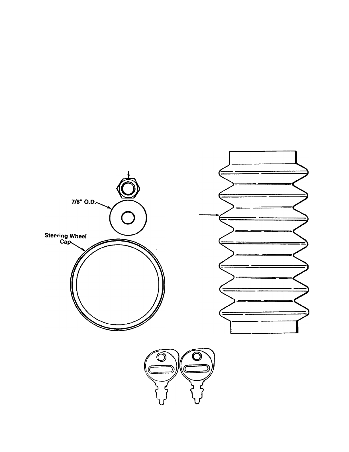
CONTENTS OF HARDWARE PACK
Remove this sheet from your owner’s manual and lay the hardware on the illustration for identification purposes.
After assembly, keep the Slope Gauge which is on the reverse side of this sheet for future use.
(Hardware pack may contain extra items which are not used on your unit.)
INSTALLING THE BATTERY
Cable
Tie
ATTACHiNG THE
B
STEERING WHEEL
_1_
Hex Nut
5/16-24 Thread
Cupped Washer
5/16“ I.D. X
ac>
IGNITION KEYS
cT
(May Be
Attached to
Tractor)
Steering
Beiiow
r
c
>
c
(C
w
r
I I I I I I I I I
0 1
WCMES
I ! I I I I I I I I I I I I I
2 3
Page 5

IMPORTANT
THIS SYMBOL POINTS OUT IMPORTANT SAFETY INSTRUCTIONS WHICH. IF NOT FOLLOWED, CO! 'LD ENDANGER THE PERSON
AL SAFETY AND/OR PROPERTY OF YOURSELF AND OTHERS. READ AND FOLLOW ALL INSTRUCTIONS IN THIS MANUAL
A
BEFORE ATTEMPTING TO OPERATE YOUR UNIT. WHEN YOU SEE THIS SYMBOL— A HEED ITS WARNING.
SAFE OPERATION PRACTICES
DANGER:
This cutting machine Is capable of amputating hands and feet and throwing ob|ects. Failure to observe
the following safety instructions could result in serious injury or death.
A
I. GENERAL OPERATION
1. Read, understand, and follow all instructions in the manual and
on the machine before starting. Keep this manual in a safe
place for future reference and for ordering repiacement parts.
2. Only allow responsible adults familiar with the instructions to
operate the machine. Know controls and how to stop the
machine quickiy.
3. Do not put hands or feet under cutting deck or near rotating
parts.
4. Ciear the area of objects such as rocks, toys, wire, etc. which
could be picked up and thrown by the blade. A small object
may have been overlooked and could be accidentally thrown by
the mower in any direction and cause injury to you or a
bystander. Aiways wear safety glasses or eye shields during
operation or whiie performing an adjustment or repair, to pro
tect eyes from foreign objects. Stop the blade(s) when cross
ing gravel drives, walks or roads.
5. Be sure the area is clear of other people before mowing. Stop
machine if anyone enters the area.
6. Never carry passengers.
7. Disengage blade(s) before shifting into reverse and backing up.
Always look down and behind before and while backing.
8. Be aware of the mower and attachment discharge direction and
do not point it at anyone. Do not operate the mower without
either the entire grass catcher or the chute guard in piace.
9. Slow down before turning. Operate the tractor smoothly. Avoid
erratic operation and excessive speed.
10. Never leave a running machine unattended. Always turn off
blade(s), place transmission in neutral, set park brake, stop
engine and remove key before dismounting.
II. Turn off blade(s) when not mowing.
12. Stop engine and wait until blade(s) comes to a complete stop
before (a) removing grass catcher or unclogging chute, or (b)
making any repairs, adjusting or removing any grass or debris.
13. Mow only in daylight or good artificial light.
14. Do not operate the machine while under the influence of alco
hol or drugs.
15. Watch for traffic when operating near or crossing roadways.
16. Use extra care when loading or unloading the machine into a
trailer or truck. This unit should not be driven up or down a
ramp onto a trailer or truck under power, because the unit
could tip over, causing serious personal injury. The unit must
be pushed manually to load or unload properly.
17. Never make a cutting height adjustment while engine is run
ning if operator must dismount to do so.
18. Wear sturdy, rough-soled work shoes and close-fitting slacks
and shirts. Do not wear loose fitting clothes or jewelry. They
can be caught in moving parts. Never operate a unit in bare
feet, sandals, or sneakers.
19. Check overhead clearance carefully before driving under power
lines, wires, bridges or low hanging tree branches, before
entering or leaving buildings, or in any other situation where
the operator may be struck or pulled from the unit, which,
could result in serious injury.
20. Disengage all attachment clutches, thoroughly depress the
brake prdal, and shift into neutral before attempting to start
engine.
II. SLOPE OPERATION
Slopes are a major factor related to loss of control and tip-over
accidents which can result in severe injury or death. All slopes
require extra caution. If you cannot back up the slope or if you feel
uneasy on it, do not mow it.
DO:
Mow up and down slopes, not across.
Remove obstacles such as rocks, limbs, etc.
Watch for holes, ruts or bumps. Uneven terrain could overturn ih-;
machine. Tall grass can hide obstacles.
Use slow speed. Choose a low enough gear so that you will not
have to stop or shift while on the slope. Always keep tractor in gear
when going down slopes to take advantage of engine braking
action.
Follow the manufacturer’s recommendations for wheel v/eights or
counterweights to improve stability.
Use extra care with grass catchers or other attachments. These can
change the stability of the machine.
Keep all movement on the slopes slow and gradual. Do not make
sudden changes in speed or direction. Rapid engagement or brak
ing could cause the front of the machine to lift and rapidly flip over
backwards which could cause serious injury.
Avoid starting or stopping on a slope. If tires lose traction, disen
gage the blade(s) and proceed slowly straight down the slope.
For your safety, use the slope gauge included as part of this manual
to measure slopes before operating this unit on a sloped or hilly
area. If the slope is greater than 15° as shown on the slope gauge,
do not operate this unit on that area or serious injury could result.
DO NOT:
Do not turn on slopes unless necessary; then, turn slowly and
gradually downhill, if possible.
Do not mow near drop-offs, ditches or embankments. A wheel over
the edge or an edge caving in could cause sudden overturn.
Do not mow on wet grass. Reduced traction could cause sliding.
Do not try to stabilize the machine by putting your foot on the
ground.
Do not use grass catcher on steep slopes.
III. CHILDREN
Tragic accidents can occur if the operator is not alert to the pres
ence of children. Children are often attracted to the machine and
the mowing activity. Never assume that children v;ill remain where
you last saw them.
1. Keep children out of the mowing area and in watchful care of
an arfult other than the operator.
2. Be alert and turn machine off if children enter the area.
3. Before and when backing, look behind and down for small chil
dren,
4. Never carry children. They may fall off and be seriously injured
or interfere with the safe machine operation.
5. Never allow children under 14 years old to operate the
machine. Children 14 years and over should only operate
machine under close parental supervision and proper instruc
tion.
6. Use extra care when approaching blind corners, shrubs, trees
or other objects that may obscui e vision.
Page 6
IV. SERVICE
1. Use extra care in handling gasoline and other fuels. They are
flammable and vapors are explosive.
a. Use only an approved container.
b. Never remove gas cap or add fuel \with the engine running.
Allow engine to cool at least two minutes before refueling.
Do not smoke.
c. Never refuel the machine indoors.
d. Never store the machine or fuel container inside where
there is an open flame, or spark, such as a water heater,
space heater, clothes dryer and the like.
2. Never run a machine inside a closed area.
3. Check ^ equently and keep nuts and bolts, especially blade
attachment bolts, tight and keep equipment in safe working
condition.
4. Never tamper with safety devices. Check their proper operation
regularly. Use all guards as instructed in this manual.
5. To reduce fire hazard, keep machine free of grass, leaves or
Your unit was built to be operated according to the rules for safe ope tion in this manual. As with any type
DANGER: of power equipment, carelessness or error on the part of the operator can result in serious injury. If you vio
late any of these rules, you may cause serious injury to yourself or n'hers.
ASSEMBLY INSTRUCTIONS
other debris build-up. Clean up oil or fuel spillage. Allow
machine to cool before storing.
6.
Stop and inspect the equipment for damage if you strike an
object. Repair, if necessary, before re-starting and operating
the machine.
Never make adjustments or repairs with the engine running.
Grass catcher components are subject to wear, damage and
deteriorate, which could expose moving parts or allow objects
to be thrown. Frequently, check components and replace with
manufacturer’s recommended parts when necessary.
9.
Mower blades are sharp and can cut. Wrap the blade(s) or
wear gloves and use extra caution when servicing blade(s).
Check brake operation frequently. Adjust and service as
10.
required.
11.
Muffier, engine, and belt guards become hot during operation
and can cause a burn. Allow to cool down before touching.
12.
Do not change the engine governor settings or overspeed the
engine.
IMPORTANT: After assembly, service engine with
gasoline, and check oil level as instructed in the
engine section of this manual.
NOTE: Reference to right or left hand side of the
unit is observed from the driver’s seat, facing for
ward.
UNPACKING
1. Remove the lawn tractor from the carton as follovi/s. Open the top flaps. Remove all loose parts
and carton inserts. Cut the front corners.of the
carton. Make certain brake is released, and push
the unit out of the carton.
2. Remove page four from this manual and lay the
contents of the hardware pack on the illustration
for identification.
Screwdriver
BAHERY INF0Rr'" ATI0N
WARNING
A
A. Battery acid must be handled with great care as
contact with it can burn and blister the skin. It is
also advisable to wear protective clothing (goggles,
rubber gloves and apron) when working with it.*
B. Should battery acid accidentally splatter into the
eyes or onto the face, rinse the affected area
immediately with clean cold water. If there is any
further discomfort, seek prompt medical attention.
C. If acid spills on clothing, first dilute it with clean
water, then neutralize with a solution of ammonia/
water or baking soda/water.
D. Since battery acid is corrosive, do not pour it into
any sink or drain. Before discarding empty elec
trolyte containers, rinse them with a neutralizing
solution.
E. NEVER connect or disconnect charger clips to bat
tery while charger is turned on as it can cause
sparks.
F. Keep all lighted materials (cigarettes, matches,
lighters) away from the battery as the hydrogen gas
generated during charging can be combustible.
G. As a further precaution, only charge the battery in
d well-ventiiated area.
*Always shield eyes, protect skin and clothing
when working near batteries.
ACTIVATING THE BAHERT
Do not activate battery (fill with battery acid) until
battery is actually placed in service. Be certain to
read previous warnings before activating ifie h-Ltery.
1. Open the battery box (located under the seat) by
pressing in on the end (right hand side) and lifting
up. Remove the batteiV. The clear plastic drain
lube should be attached to the battery.
Open the battery pack. Be careful riot to puncture
2.
the box. It contains the battery fluid (acid) in a
plastic container and one short plastic tube.
Page 7
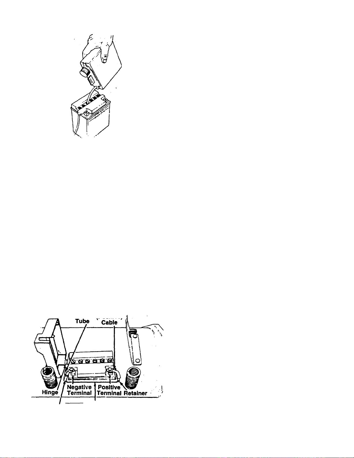
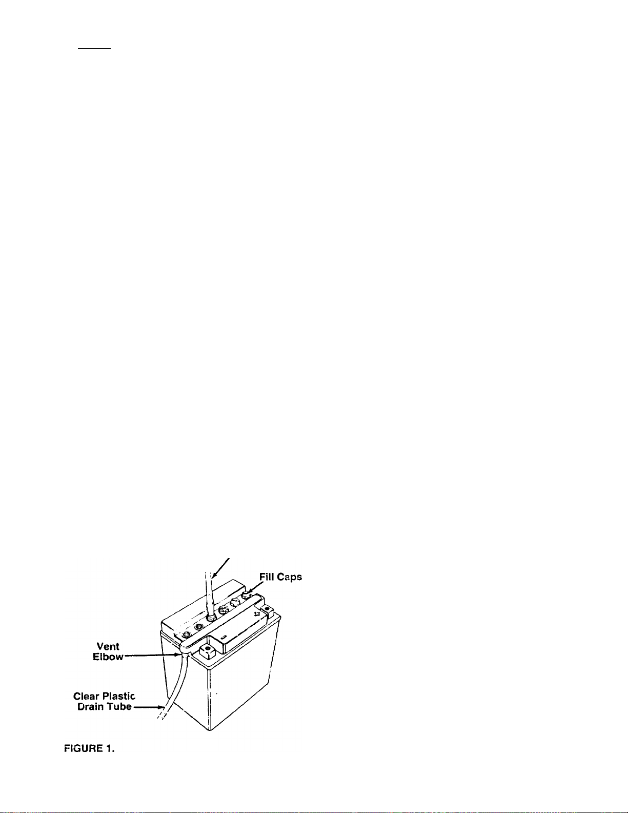
FIGURE 2.
DANGER
▲
Battery contains sulfuric acid. Refer to warning
on page 6. Antidote: EXTERNAL—Flush with
water. INTERNAL—Drink large quantities of water
or milk. Follow with milk of magnesia, beaten eggs
or vegetable oil. Call physician immediately. EYES;
Flush with cool water for at least 15 minutes, then
get prompt medical attention.
Since batteries produce explosive gases, keep
all lighted materials (cigarettes, lighters, match
es, etc.) away. Be sure to charge battery only in
well-ventilated areas. Make certain venting path of
battery (drain tube) is always open.
KEEP BATTERIES
OUT OF THE REACH OF CHILDREN!
Battery Red
Drain rpositivel
Black
(Negative)
Cable
FIGURE 3.
Battery
Box
3. Place the battery on a table or workbench. Make
certain the long plastic drain tube is in place on
the vent elbow.
4. Remove the six fill caps from the top of the bat
tery with a screwdriver. Be careful not to damage
the fill caps. See figure 1.
‘ 5. Place the battery fluid container on the table or
workbench. Carefully cut off tip of the spout and
attach the short plastic tube provided. Do not
squeeze the container when cutting tip.
6. Fill each battery cell slowly and carefully to the
UPPER LEVEL line marked on battery. See fig
ure 2. Use caution as the acid level will rise rapid
ly after the bottom of the cell is filled.
7. Allow battery to stand for 30 minutes with the fill
caps removed, while the plates absorb acid.
8. If acid level has fallen after the 30 minute stand
ing period, refill each cell with battery acid to the
UPPER LEVEL line on battery. Replace the fill
caps.
9. Before discarding the empty container, neutralize
any residue with baking soda and rinse container
with water. Puncture container several times
before discarding.
10. Charge the battery after the 30 minute standing
period. SLOW CHARGE THE BATTERY (DO
NOT FAST CHARGE) at a meiximum bench rate
of 1.4 amperes until the specific gravity reading is
1.260-1.280. Charge for a minimum of 2 hours
and a maximum of 8 hours.
NOTE: This engine is equipped with an alternator.
The current for the battery charger alternator is unreg
ulated. During normal operation, it is only necessary
to charge the battery:
1. When it is activated for the first time.
2. Before winter storage.
3. Before using the lawn tractor after winter storage.
NOTE: Charging rate after battery has been put into
operation—the battery is to be charged for a period of
14-16 hours. NO LONGER THAN 30 HOURS.
After battery has been charged, add only distilled
water. Do not add acid.
INSTALLING THE BAHERY (Hardware A)
1. Lift the seat.
2.
Make certain the positive cable (heavy red wire)
extends through the retainer on the right side of
the battery box. The negative cable (heavy black
wire) should be routed up along the left side of
the battery box.
Place the battery inside the battery box so that
the positive terminal is toward the right side of the
unit. See figure 3. Route the battery drain tube
down beside the battery box.
4.
Remove the bolt on the positive terminal of the
battery. Place the positive (+) red cable on the
terminal. Secure with the bolt. Be careful not to
lose the nut which is inside the terminal.
5.
Attach the negative (-) black cable in the same
manner.
Page 8
Steering
Wheel Cap
Steering etaari««
Wheel Steering
Bellow
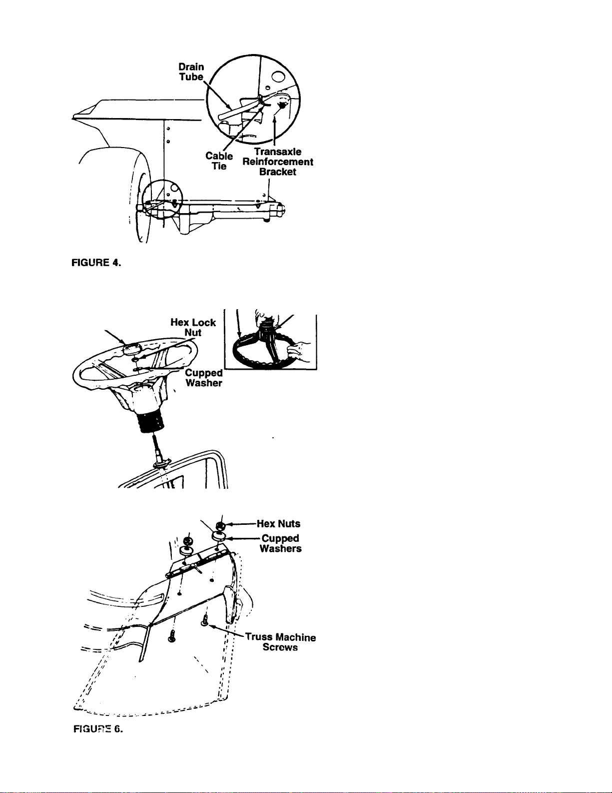
6. Route the drain tube through the opening
between the transaxle reinforcement bracket and
the frame on the left rear of the unit. Insert the
drain tube to the transaxle reinforcement bracket
through the cable tie which is attached as shown
in figure 4. Be certain drain tube is routed away
from the wheel rim. Trim excess end of cable tie
and drain tube (leave approximately 1” below
lawn tractor frame).
Close the top of the battery box.
AHACHING THE STEERING WHEEL (Hardware B)
1. Attach one end of steering bellow to the steering
------
wheel as shown in figure 5, inset.
With the wheels of the tractor pointing
2.
straight forward, place the steering wheel and
steering bellow over the steering shaft, position
ing steering wheel as desired.
Place the washer with the cupped side down over
3.
the steering shaft. Secure with 5/16" hex lock nut.
See figure 5.
Place the steering wheel cap over the center of
the steering wheel and seat it with your hand.
FIGURE 5.
AHACHING THE CHUTE DEFLECTOR
1. Remove the truss machine screws, cupped wash
ers and hex jam nuts which are attached to the
deck next to the chute opening.
2. Place the chute deflector in position as shown in
-fioure 6 Secure with hardware rjst removed
WARNING: Do not operate your unit
unless the chute deflector has been
▲
properly installed.
Page 9
CONTROLS
Throttle
Control
Choke
Clutch-Brake
Pedal
Ammeter
Ignition
witch
Light Switch
Speed
Control
Lever
FIGURE 7.
THROnLE CONTROL
The throttle control is used to regulate the engine
speed. To get maximum efficiency from cutting, the
throttle should be in the FAST position when operat
ing the mower. See figure 7.
CHOKE CONTROL
The choke control is located on the dashboard and is
operated manually. Details for the choke operation are
covered in the separate engine manual. See figure 7.
SPEED CONTROL LEVER
The speed control lever allows you to regulate the
ground speed of the lawn tractor. See figure 7. To
select the ground speed, depress clutch pedal. Push
speed control lever inward and move downward to
slow lawn tractor, move upward to increase speed.
When desired speed has been obtained, release lever
in that position. Whenever clutch is engaged, unit will
automatically go to the pre-set speed.
IGNITION SWITCH
Turn the key to the START position to start the
engine. When the engine is running, let the key return
to the ON position. To stop the engine, turn the key to
the left to the OFF position and remove it to prevent
accidental starting. See figure 7
LIGHT SWITCH
Push ligh* cwitf'h to turn cn the lights. The 'ights will
only operate when the engine is running. See figure 7.
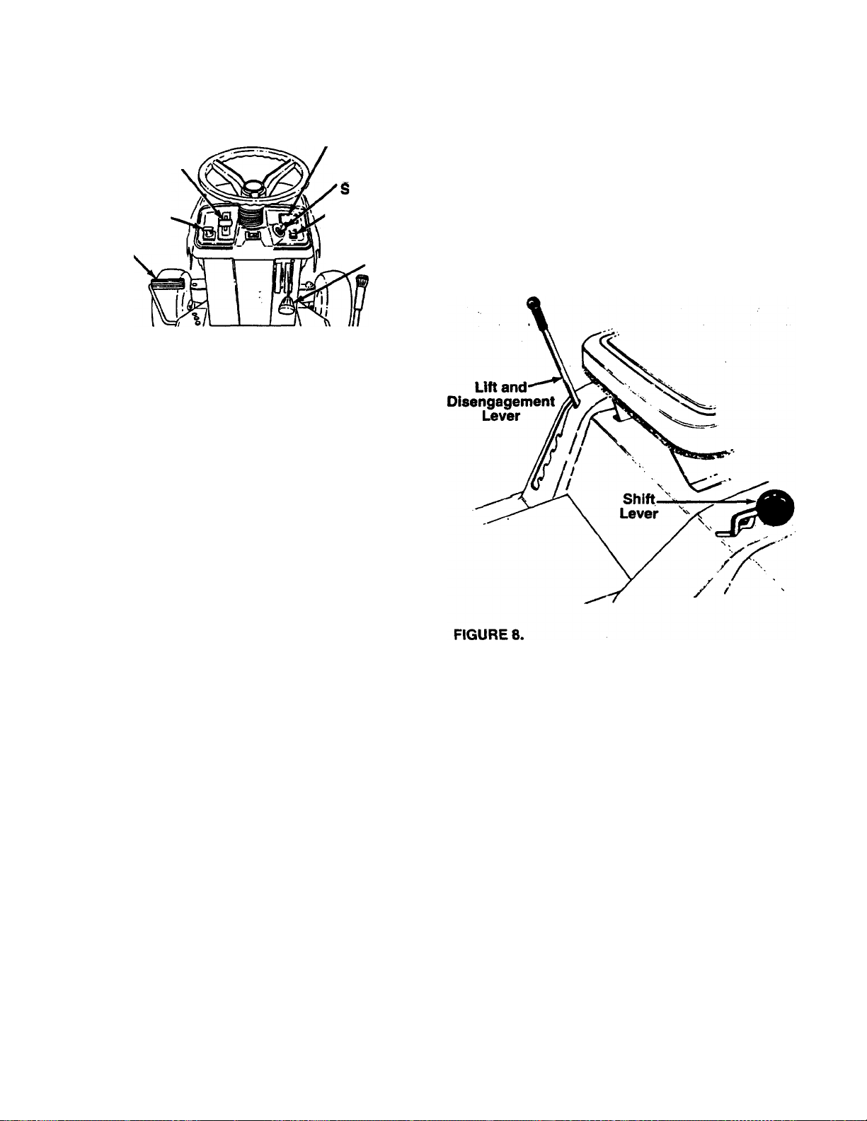
SHIFT LEVER
T.ha shift lever is located on the left fender and has
three positions, FORWARD, NEUTRAL and
REVERSE. See figure 8. The clutch-brake pedal must
be depressed and the lawn tractor must not be mov
ing when shifting gears. Do not force the shift lever.
Release the clutch-brake pedal slightly to line up tho
shifting collar in the transmission. Then try to shift
gears.
CLUTCH-BRAKE PEDAL
The clutch-brake pedal is located on the left side of
the lawn tractor. Depressing the clutch-brake pedal
part way disengages the clutch. Pressing the pedal all
the way down disengages the clutch and engages the
disc brake. See figure 7.
NOTE: The clutch-brake pedal must be depressed to
start the engine.
PARKING BRAKE
The speed control lever is used to set the parking
brake. To set the parking brake, depress the clutchbrake pedal. Press the speed control lever inward and
all the way down. Release the speed control lever and
the clutch-brake pedal.
To release the parking brake, depress the clutchbrake pedal, press the speed control lever inward and
move to desired position. Release the speed control
lever and the clutch-brake pedal.
\
NOTE: The parking brake must be set if the operator
leaves the seat with ihe engine running.
FIFT AND niSENGAGEMENT LEVER
The lift and disengagement lever is used to raise and
lower the cutting deck which determines the cutting
height. Pulling it all the way back and locking it disen
gages the blades. The lift and disengagement lever
must be in the disengaged position when starting the
engine, when shifting into reverse or if the operator
leaves the seat. See figure 8.
9
Page 10

AMMETER
The ammeter registers the rate of battery charge or
discharge. The ammeter will register on the discharg
ing side when starting the engine. It should register on
the opposite side (charging) when the engine is run
ning in the fast position until the battery is completely
charged. With a fully charged battery or with the
engine idling, the ammeter will not show a charge.
INTERLOCKS (Not Shown)
Interlock safety switches are located by the clutchbrake pedal, the lift and disengagement lever, the
shift lever and under the seat.
Before the engine will start, the clutch-brake pedal
must be depressed all the way and the lift and disen
gagement lever must be in the disengaged position.
Before the unit can be shifted into reverse or if the
operator leaves the seat, the lift and disengagement
lever must be in the disengaged position.
OPERATION
A
AVOID SERIOUS INJURY OR DEATH
60 UP AND DOWN SLOPES. NOT ACROSS. • AVOID SUDDEN TURNS.
DO NOT OPERATE THE UNIT WHERE IT COULD SLIP OR TIP.
IF MACHINE STOPS GOING UPHILL, STOP BLADE(S) AND BACK
DOWNHILL SLOWLY.
DO NGT MOW WHEN CHILDREN OR OTHERS ARE AROUND.
NEVER CARRY CHILDREN.
LOOI'v DOWN AND BEHIND BEFORE AND WHILE BACKING.
KEEP SAFETY DEVICES (GUARDS, SHIELDS, AND SWITCHES) IN
PLACE AND WORKING.
REMOVE OBJECTS THAT COULD BE THROWN BY THE BLADE(S).
KNOW LOCATION AND FUNCTION OF ALL CONTROLS.
BE SURE BLADE(S) AND ENGINE ARE STOPPED BEFORE PLACING
HANDS OR FEET NEAR BLADE(S).
BEFORE LEAVING OPERATOR'S POSITION, DISENGAGE BLADE(S),
PLACE THE SHIFT LEVER IN NEUTRAL, ENGAGE BRAKE LOCK, SHUT
ENGINE OFF AND REMOVE KEY.
READ OPERATOR’S MANUAL
TIRE PRESSURE
Tne tires on your unit may be over-inflated for ship
ping purposes. Reduce the tire pressure before oper
ating the unit. Recommended operating tire pressure
is approximately 12 p.s.i. (check sidewall of tire for tire
manufacturer’s recommended pressure).
WARNING: Maximum tire pressure under
ik
any circumstances is 30 p.s.i. Equal tire
pressure should be maintained on all
tires.
GAS AND OIL FILL-UP
NOTE: To open the hood, simply lift up on both sides
of the hood.
WARNING
Service the engine with gasoline, and check oil
level as Instructed In the separate engine manual
packed with your unit. Read instructions carefully.
IMPORTANT: Your tractor is shipped with oil; how
ever, you must check the oil level before operating
and add if necessary. Be careful not to overfill.
WARNING: Never fill fuel tank indoors,
with engine running or while engine is
A
STARTING THE ENGINE
1. Depress the clutch-brake pedal and set the park
2. Place the lift and disengagement lever in the DIS
NOTE: This unit is equipped with a safety interlock
system for your protection. The purpose of the safety
interlock system is to prevent the engine from crank
ing or starting unless the clutch-brake pedal is
depressed and the lift and disengagement lever is in
the disengaged position. In addition, the lift and disen
gagement lever must be in the disengaged position
when the unit is put into reverse or the engine will
shut off. If the operator leaves the seat with the lift
and disengagement lever engaged and/or without set
ting the parking brake, the engine will shut off.
A
3.
4.
6,
hot.
ing brake.
ENGAGED position. See figure 8.
WARNING: Do not operate the lawn trac
tor if the interlock system is malfunction
ing because it is a safety device,
designed for protection.
Set the throttle control in the FAST position. See
figure 7.
Pull out choke knob to choke engine. (A warm
engine may not require choking.)
Turn the ignition key to the START position.
When the engine is running, let the key return to
the ON position. See figure 7.
Push choke knob in gradually. Move ♦he throttle
control to desired engine speed.
STOPPING THE ENGINE
Turn the ignition key to the left to the OFF position.
Remove the key to prevent accidental starting.
IMPORTANT: If you strike a foreign object, stop the
engine. Remove wire from spark plug, thoroughly
inspect the unit for any damage, and repair the dam
age before restarting and operating the mower.
NOTE: If any problems are encountered, refer to ths
Trouble Shooting Guide on page 19.
10
Page 11
OPERATING THE LAWN TRACTOR
1. start the engine as instructed previously.
2. Move throttle control to 3/4 or full throttle to pre
vent strain on the engine and to operate the cut
ting blades.
3. Place the shift lever in either the FORWARD or
REVERSE position.
WARNING: Look to the rear before back
A.
4. Release the parking brake by depressing the
5. Release clutch-brake pedal slowly to put unit into
6. The lawn tractor is brought to a stop by depress
NOTE: When operating the unit initially, there will be
little difference between the highest two speeds untii
after the belts have seated themselves into the pul-
leys during the break-in period. Be certain to change
oil in the crankcase after the first 5 hours of operation.
Be sure that the lawn is clear of stones, sticks, wire,
or other objects which could damage lawn tractor, or
the debris could be thrown by the blade in any direc
tion and cause an injury. For best results and to
insure more even grass distribution, do not mow when
lawn is excessively wet.
A
When stopping the unit to empty a grass bag, etc., fol
low the instructions above. This procedure will also
eliminate “browning" the grass, which is caused by
hot exhaust gases from a running engine.
If unit stalls with speed control in high speed, or if
unit will not operate with speed control lever in a low
speed position, proceed as follows.
1. Place sliiiE lever in NEUTRAL.
2. Restart engine.
3. Place speed control lever in high speed position.
4. Release clutch-brake pedal fully.
5. Depress clutch-brake pedal.
6. Place speed control lever in desired position.
7. Place shift lever in either FORWARD or
ing up.
clutch-brake pedal, pressing outward on the
speed control lever and moving to desired posi
tion. Use first speed position when operating the
lawn tractor for the first time.
motion.
ing the clutch-brake pedal.
WARNING: Before leaving the operator’s
position for any reason, disengage the
blades, place the shift lever in neutral,
engage the parking brake, shut engine
off and remove the key.
REVERSE, and follow normal operating proce
dures.
OPERATING THE CUHING BLADES
The cutting blades may be engaged while the lawn
tractor is moving or standing still. DO NOT engage
the cutting blades abruptly as the sudden belt tension
on the pulley may cause the engine to stall.
WARNING: When the blade drive is
engaged, keep feet and hands away from
A
Move the lift and disengagement lever into the DIS
ENGAGED position to raise the deck and disengage
the blades.
the discharge opening, the blades or any
part of the deck. When the unit is used
for other than mowing, the blade drive
should be disengaged.
ADJUSTMENTS
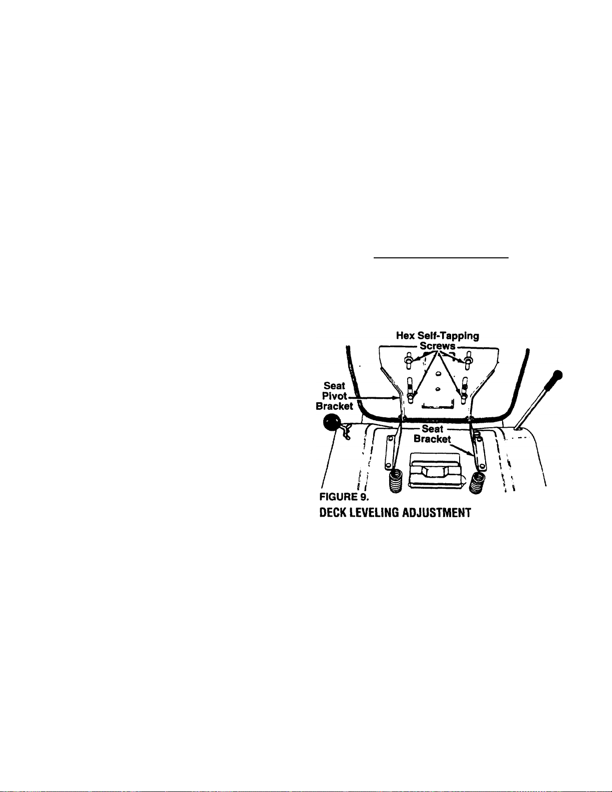
SEAT ADJUSTMENT
To adjust the position of the seat, loosen the four self
tapping screws on the bottom of the seat. See figure
9. Slide the seat forward or backward as desired.
Retighten the self-tapping screws.
If an uneven cut is obtained, the deck may be leveled
as follows.
1. Move the lift and disengagement iever forward
(lower the cutting deck).
2. With unit on hard, level surface, measure the dis
tance from the bottom edge of the center of the
left side of deck to the ground. Measure the same
diotance just behind the chute area on ihe right
side of the deck. Or, place me blades in a straight
line, and measure the distance from the outside
edge of the blade tips to the ground.
3. Disconnect the adjustable deck links from the
deck lift pivot brackets on the left side of the unit
by removing the hairpin clips and flat washers.
See figure 10.
4. Thread the adjustable links in or out as neces
sary. Reassemble the links. Check the adjust
ment, and readjust as necessary.
11
Page 12

SPEED CONTROL ADJUSTMENT (See Figure 11)
NOTE: When operating the unit initially or after
replacing the belts, there will be little difference
between the highest two speeds until after the belts
have gone through a break-in period and have seated
themselves into the pulleys.
First, adjust the speed control lever as follows:
1. Place the shift lever in Neutral position.
2. Start the engine.
3. Place the speed control lever in high speed posi
tion.
4. Release the clutch-brake pedal completely, then
slowly depress the pedal all the way (to disen
gaged position). Hold the pedal in this position.
5. Turn the engine off.
6. After engine stops completely, release the clutch-
brake pedal.
7. Disconnect the speed control link from the vari
able speed bracket by removing the hairpin clip
and flat washer from the stud located on the bot
tom side of the variable speed bracket.
8. Depress the clutch-brake pedal forward until the
stop on the clutch-brake pedal assembly hits
solidly against the underside of the frame.
9. Remove the hairpin clip and flat washer from the
rod attached to the back of the speed control
lever.
10. Place the speed control lever in parking brake
position.
11. Thread the ferrule on the rod until the ferrule slips
into the bottom end of the slot in the speed con
trol lever, then thread the ferrule do^vn on the rod
one full turn (to shorten).
12. Place speed control lever in first position.
13. Place ferrule into speed control lever slot, and
secure with fiat washer and hairpin clip. Release
the clutch-brake pedal.
FIGURE 11.
Next, adjust the speed control link as follows to obtain
the correct neutral adjustment.
1. Push the clutch-brake pedal backward by hand
as far as it will go using light pressure. Hold it in
this position as you make the following adjust
ment.
2. Thread the speed control link into or out of the
ferrule until the eyelet on the opposite end of the
link slips onto the stud on the bottom side of the
variable speed bracket.
3. Secure the speed control link to the variable
speed bracket with flat washer and hairpin clip.
NEUTRAL .ADJUSTMENT (Wheel Drive)
1. Place the transmission in neutral. (The unit will
move freely when pushed forward and backward
with the parking brake released.)
2. Loosen the bolt which secures the shift lever
assembly to the shift lever adjusting link. See fig
ure 12.
3. Place the shift lever in the neutral slot. See figure
12.
4. Tighten the belt to 13 foot pounds.
12
Page 13

CUTTING DECK ENGAGEMENT ADJUSTMENT
The cutting deck engagement may be adjusted to
make certain deck is disengaged when lift and disen
gagement lever is in the disengaged position, or to
obtain more drive in the cutting positions. Correct
adjustment as follows.
Place the lift and disengagement lever in the highest
cutting position (first notch down from disengaged
position). The approximate adjustment is to have the
lock nut on the threaded rod (above the rear of the
deck) touching the end of the tubing. See figure 13.
Threaded
Rod
Move the lock nut toward the tubing to start to disen
gage the deck earlier. Move the lock nut away from
the tubing to obtain more drive in the cutting positions.
WARNING: Make certain the unit is
ad]usted so that the cutting blades are
A
WHEEL ADJUSTMENT
The caster (forward slant of the king pin) and the
camber (tilt of the wheels out at the top) require no
adjustment. Automotive steering principles have been
used to determine the caster and camber on the trac
tor. The front wheels should toe-in 1/8 inch.
To adjust the toe-in, follow these steps.
1. Remove the hex nut and lock washer, and drop
2. Loosen the hex jam nut on tie rod.
3. Adjust the tie rod assembly for correct toe-in.
disengaged when the lift and disengage
ment iever is in the disengaged position.
the tie rod end from the wheel bracket. See figure
14.
(See figure 14.) Retighten hex jam nut.
Tie
Rod
Hex
:Jam
Nut
Hex Nut
Lock Washer
Tie Rod'
End
FIGURE 14.
Dimension "B” should be approximately 1/8" less than
Dimension “A.” See figure 15.
A. ) To increase Dimension “B,” thread the rod into
tie rod end.
B. ) To decrease Dimension "B,” unscrew the tie rod
from the tie rod end.
C. ) Reassemble tie rod. Check dimensions. Readjust
if necessary.
13
Page 14

(1/8" less than A)
FIGURE 15.
CARBURETOR ADJUSTMENT
WARNING: If any adjustments are made
to the engine while the engine is running
A
Minor carburetor adjustment may be required to
compensate for differences in fuel, temperature,
altitude and load. To adjust the carburetor, refer to
the separate engine manual packed with your unit.
NOTE: A dirty air cleaner will cause an engine to run
rough. Be certain air cleaner is clean and attached to
the carburetor before adjusting carburetor.
BRAKE ADJUSTMENT (See figure 16)
The brake is located by the left rear wheel inside the
frame. During normal operation of this machine, the
brake is subject to wear and will require periodic
examination and adjustment.
A
NOTE: Yo'r b'ake may be eq pped with a !gJ< nut
instead nf the castle nut and cotter pin shown in *igure
1C.
(e.g. carburetor), disengage all clutches
and blades. Keep clear of all moving
parts. Be careful of heated surfaces and
muffler.
WARNING: Do not have the engine run
ning when you adjurt the brake.
Brake
Lever
Cotter Pin
Axle'i
Housing
FIGURE 16.
LUBRICATION
WARNING: Always stop engine and dis
connect spark plug wire before cleaning,
A
STEERING GEARS
Lubricate teeth of steering gears with automotive
multi-purpose grease after every 25 hours of opera
tion or once a season.
STEERING SHAFT
Lubricate steering shaft at least once a season with
light oil.
TRANSAXLE
The transaxle is lubricated and sealed at the factory
and does not require checking. If disassembled for
any reason, lubricate with 10 oz. of grease, part num
ber 737-0148.
WHEELS
The front wheels are provided with grease fittings.
The rear wheels must be removed from the axle for
lubrication. Lubricate both front and rear wheels at
least once a season with automotive multi-purpose
grease.
PIVOT PDINTS
Lubricate all pivot poiri.i. with iigfit oil at least once a
season.
lubricating or doing any kind of work on
lawn tractor.
To aojust the brake, remove the cotter pin from the
castle nut (if so equipped). Adjust the nut so the brake
starts to engage when the brake lever is 1/4" to 5/16"
av/ay from the axle housing.
NOTE: Figure 1C is shown with the unit tipped up on
rear wheels for clarity only.
MAINTENANCE
WARNING: Disconnect the spark plug
wire and ground against the engine
before performing any ivpairs or mainte
nance.
14
Page 15

TROUBLESHOOTING
Refer to page 19 of this manual for trouble shooting
information.
ENGINE
Refer to the separate engine manual for all engine
maintenance instructions.
Maintain engine oil as instructed in the separate
engine manual packed with your unit. Read and follow
instructions carefully.
Service air cleaner every 10 hours under normal con
ditions. Clean every few hours under extremely dusty
conditions. Poor engine performance and flooding
usually indicates that the air cleaner should be ser
viced. To service the air cleaner, refer to the separate
engine manual packed with your unit.
The spark plug should be cleaned and the gap reset
once a season. Spark plug replacement is recom
mended at the start of each mowing season; check
engine manual for correct plug type and gap specifi
cations.
CUniNG BLADE
A. Removal for Sharpening or Replacement
C. Reaissembly
Before reassembling the blade and the blade adapter
to the unit, lubricate the spindle and the inner surface
of the blade adapter with light oil. Lubricating the bolt
holes, bolts and inner surface of the nuts with light oil
is also recommended. A 4 oz. plastic bottle of light oil
lubricant is available. Order part number 737-0170.
Engine oil may also be used.
When replacing the blade, be certain the wide blade
is assembled on the right side of the deck. Be sure to
install the blades with the side of the blades marked
"Bottom” (or with part number) facing the ground
when the mower is in the operating position.
Blade Mounting Torque
Center Bolt; 450 in. lbs. min., 600 in. lbs. max.
Blade Adapter Bolts: 200 in. lbs. min., 350 in. lbs. max.
To insure safe operation of your unit, ALL nuts and
bolts must be checked periodically for correct tightness.
FUEL FILTER
Your unit is equipped with a replaceable in-line fuel fil
ter. Replace filter whenever contamination or discol
oration is noticed. Order replacement filter through
your engine authorized servicer.
WARNING: Be sure to disconnect and
ground the spark plug wire and remove
A
ignition key before working on the cut
ting blade to prevent accidental engine
starting. Protect hands by using heavy
gloves or a rag to grasp the cutting
blades.
1. Remove the large bolt and lock washer which
holds the blade and adapter to the blade spindle.
2. Remove the blade and adapter from the spindle.
3. If the blade or blade adapter needs replacing,
remove the two small bolts, lock washers and
nuts which hold the blade to the adapter.
B. Sharpening
Remove the cutting blade by following the directions
of the preceding section.
When sharpening the blade, follow the original angle
of grind as a guide. It is extremely important that
each cutting edge receives an equal amount of gr'nding to prevent an unbalanced blade. An unbalariced
blade will cause excessive vibration when rotating at
high speeds, may cause damage to the mower and
could break, causing persona! injury.
The blade can be tested for balance by balancing it
on a round shaft screwdriver. Remove metal from the
heavy side until it balances evenly.
DRIVE BELT REMOVAL AND REPLACEMENT
WARNING: Disconnect the spark plug
▲
NOTE: When changing the belts, a spring puller or
other suitable tool is required to remove some of
the springs. A spring pulier (part number 732-
0571) is available to assist in removal of springs.
Removing the Deck Beit
NOTE: Figures 17, 20 and 21 are shown with the unit
wire and ground it against the engine.
Block the wheels of the unit.
tipped up for clarity. It is not necessary to tip the unit
to remove the belts.
1. Place the lift lever in the disengaged position.
2. Remove the two hex bolts (belt keepers) from the
engine pulley belt guard. See figure 17.
NOTE: It is recommended tnat the blade always be
removed from the adapter for the best test of balance.
15
Page 16

NOTE: Make certain hex bolts are reassembled as
shown in figure 17.
3. Unhook the deck belt from the engine pulley.
4. Place the lift lever in the engaged (all the way for
ward) position.
5. Disconnect the spring from the left rear transmis
sion support bracket. See figure 18.
6. Disconnect the two front deck links by removing
the hairpin clips and flat washers.
2. Disconnect the large spring from the transmission
support bracket, using a spring puller or other
suitable tool.
Variable
Loosen
7. Remove the belt guards at each deck pulley by
removing the hex bolts, lock washers and hex
nuts. See figure 19.
8. Remove and replace the belt, following the
instructions in reverse order.
Hex Bolts
Lock
Removing the Rear Drive Belt (Refer to figure 20)
1. Start the engine. Place shift lever in neutral.
Place speed control lever in high speed position
and turn engine off. Engage lift lever (move all the
way forward). Do not set parking brake.
Hex Bolts
Lock Washers
3. Disconnect the idler spring from the bolt on the
right side of the frame and transmission support
braoket.
4. Loos-; n (do not remove) the hex nut which
secures the variable speed pulley bracket to allow
clearance in order to remove the belts. A 9/16"
socket wrench is required.
5. Remove belt from transmission pulley and idler
pulley. Remove the rear drive belt from around
the top of the variable speed pulley.
6. Reassemble new belt, following instructions in
reverse order.
Removing the Forward Drive Belt (See figure 21)
1. To remove the forward drive belt, first remove the
rear drive belt (steps 1 through 5 of the preceding
instructions).
2. Remove the deck belt from the engine pullev
(steps 1 through 3 or “Removing the Deck Belt”).
3. Remove the engine pulley belt guard by removing
two self-tapping screws from eech side of the
frame. Remove the engine pulley belt guard by
moving it back and to the left.
4. Remove the forward drive belt from the engine
pulley and from the variable speed pulley.
5 Reassemble new belt, following instructions in
reverse order.
16
Page 17

Engine
BAHERY REMOVAL OR INSTALLATION
WARNING; When removing the battery,
follow this order of disassembly to pre
▲
1. Remove the Negative cable.
2. Remove the Positive cable.
To install a battery:
1. Attach the Positive cable.
2. Attach the Negative cable.
vent the screwdriver from shorting
against the frame.
BAHERY MAINTENANCE
1. Check periodically (every two weeks or before
and after charging) to be sure electrolyte level is
above the lowest line on battery. Add only dis
tilled water or a good quality drinking water.
NEVER add additional acid or other chemicals to
battery after initial activation.
2. The battery should be checked with a hydrometer
after every 25 hours of operation. If the specific
gravity is less than 1.225, remove battery and
recharge.
3. Coat the terminals and exposed wiring with a thin
coat of grease or petroleum jelly for longer ser
vice and protection against electrolyte corrosion.
4. The attery should be kept clean. Any deposits of
acid should be neutralized with soda and water.
Be careful not to get this solution in the cells.
BAHERY STORAGE
1. Charge battery using normal methods. NEVER
store discharged battery as it will not recover.
2. When storing battery for extended periods, dis
connect battery cables. Removing battery from
unit is recommended.
3. Store in cold, dry place.
4. Recharge battery whenever the specific gravity is
less than 1.225, before returning to service, or
every two months, whichever occurs first.
COMMON CAUSES FOR BAHERY FAILURE ARE:
1. Overcharging
2. Undercharging
3. Lack of water
4. Loose hold downs and/or corroded connections
5. Excessive loads
6. Battery electrolyte substitutes
7. Freezing of electrolyte
NOTE: THESE FAILURES DO NOT CONSTITUTE
WARRANTY.
JUMP STARTING
1. Attach the first jumper rab^e from the Positive ter
minal of the good battery to the Positive terminal
of the dead battery.
2. Attach the second jumper cable from the
Negative terminal of the good battery to the
FRAME OF THE UNIT WITH THE DEAD BAT
TERY.
WARNING: Failure to use this starting
procedure cou'd cause sparking, and the
gas in either battery could explode.
TIRES
Recommended operating tire pressure is approxi
mately 12 p.s4. (check sidewall of lire for tire manu
facturer’s recommended pressure). Maximum tire
pres'.ure under any circumstances is 39 p.s.i. Equal
tire pressure should be maintained on all tires.
When installing a tire to the rim, be certain rim is
clean and free of rust. I ubricate both the tiie and rim
generously. Never inflate to over 30 p.s.i. to seat
beads.
WARNING: Excessive pressure (over 30
p.s.i.) when seating beads may cause
A
17
tire/rim assembly to burst with force suf
ficient to cause serious injury.
Page 18

OFF-SEASON STORAGE
If the machine is to be inoperative for a period longer
than 30 days, prepare for storage as follows.
1. Clean the engine and the entire unit thoroughly.
2. Lubricate all lubrication points. Wipe the entire
machine with an oiled rag to protect the surfaces.
3. Refer to the separate engine manual for correct
engine storage instructions.
4. Refer to battery storage instructions on page 17.
5. Store unit in a clean, dry area. Do not store next
to corrosive materials, such as fertilizer.
NOTE: When storing any type of power equipment in
an unventiiated or metal storage shed, care should be
taken to rustproof the equipment. Using a light oil or
silicone, coat the equipment, especially any chains,
springs, bearings and cables.
GRASS COLLECTOR AVAILABLE
Grass collector stock no. 80-35106, factory no. 190-064, is available as optional equipment for the lawn tractor
shown in this manual.
WARNING: The mower should not be operated without the entire grass catcher or chute deflec
A
NOTE: Under normal usage bag material is subject to wear, and should be checked periodically. Be sure any
replacement bag complies with the mower manufacturer’s recommendations. For replacement bags, use only fac
tory authorized replacement bag.
tor in place.
18
Page 19

TROUBLE SHOOTING GUIDE
TROUBLE
Engine will not
crank
LOOK FOR
Battery Installed Incor
rectly
Blown fuse or circuit
breaker
Battery is dead or weak Use a hyaromete' to check the condition nf the bat'eny. The Specific Gravity (s.g.) should be 1.265 at
The battery must be installed with the negative terminal, identified at the terminal post by iNeg, N or
-), grounded. The positive terminal (Pos, P or +) att=<ch6S to the large cable from the solenoid. The
sme'i red wire from the fuse holder or circuit breaker is also attached to the positive terminal.
Replace fuse with 7-1/2 amp. automotive type fuse. Fuses seldom fail without a reason. The problem
must oe corrected. Check for loose connections in the fuse holder. Replace fuse holder if necessary. A
det-d short may be in the cranking or charging circuit where the Insulation may have rubbed through
and exposed the bare wire. Replace the wire or reoair with electrician's tape if the wire strands have
not been vlamaged.
Note; Look for a wire pinched between body panels, burned by the exhaust pipe or muffler or rubbed
against a moving part.
80“F. (1.215 i g. minimum needed for cranking engine). The reason for the battery failing must be
determined. (1) Defective battery. Battery will not accept or hold a full charge. (2) Short cir.cuit. Check
for grounded wire. (3) Charging system not working.
The charging system is an alternator loca cd under the flywheel. It is unregulated and rated 3 amp. at
3600 r.p.m. A diode (rectifier) is located in the output lead just before the wire harness plug on the
engine side.
REMEDY
To Alternator
Engine crariks
but will not start
Mechanical failure
(Wires and switches)
Throttle or choke not in
starting position
No spark to spark plug
The ciede changes A.C. to D.C. to charge the battery. A bad diode can either fail to charge the battery
or discharge the battery if the alternator is shorted as well as the diode. To test: (1) Disconnect charger
lead from the battery (small red wire). (2) Connect 12 V small test lamp between the 3 amp. D.C.
ctierge lead ana the positive terminal of the battery. (3) With tt.e engine off, the lamp should not light. If
it ooes, the diode and possibly the alternator should be replaceo. (4) Start the engine. The lamp should
light. If it does not, the alternator (stator) or load wire is bad ar.d should be replaced.
The interlock system includes two mechanical activated switches which are wired in series in the
circuit used to energize the starter solenoid. While testing the interlock system, you will make the
mcv;er temporarily unsafe by permitting the engine to be started with the blade and clutch engaged.
WARNING: Wtiile testing, disengage the clutch, shut off the blade control, set the parking brake and
place the gear shift lever in neutral. Attach a wire (minimum 13 gauge) to the positive terminal of the
battery and touch the other ond to the small terminal on the solenoid. If the engine does not crank:
(1) There's e loose connection or poor ground. (2) The solenoid may be bad. The solenoid can be
chucked by ur ng a heavy wire (#8 gauge minimum) and jumping be'ween the two large terminals. If
ttic engine cranks, the solenoid is bad. IT| If the engine does nor crank when you jump the solenoid,
ha.'e the starter motor tested by an .cuthonzed engine dealer. If the engine ooes crank, the pi'oblem is
with one ot the safety switches, ignition sv'itch or the wire between th; fuse holder (or circuit breaker)
-ng ih? smail tP'mlnal on the sr'eroid. Nole- bcc '■ <o's, poor t oil t-c'io.n a* 'he switcher or a Jefcc'.iva
switcit. Replace ,1 necessary.
Chock owner’s guide for correct position for throttle control and choke for starting.
Spark plug lead disconnected. Connect lead Hold spark plug lead away from engine block about 1/8".
Crank engine. There should be a spark, if not, have engine repaired at authorized engine service
dealer.
Fa:il*y spark plug. To test, remove spark plug. Attach spark plug lead to spark plug. Ground the spark
plug body against the engine block. Crarik the engine. The spark p'ug should fire at the electrode.
Rpolace if it does not.
19
Page 20

TROUBLE SHOOTtNG GUIDE (Continued)
TROUBLE LOOK FOR REMEDY
No fuel to the carburetor Gasoline tank empty. Fill.
Fuel line or in-line fuel filter plugged. Remove and clean fuel line. Replace filter if necessary.
Air filter dirty If the air cleaner is dirty, the engine may not stait. Clean or replace as recommended by the engine
manufacturer.
Engine smokes Engine loses crankcase
Excessive
vibration
Mower will not
discharge
grass or leaves
uncut strips
vacuum
Bent or damaged blade
spindle
Bent bla fe
Engine speed low
Transmission selection
Blades short or dull
Dipstick not seated or broken. Replace defecliv- part.
Engine breather defective. Replace.
Stop engine immediately. Check all pulleys, blade adapters, keys and bolts for tightness and
damage. Tighten or replace any dam.aged parts.
Stop engine Immediately. Replace damaged blade. Only use original equipment blades.
Throttle must be set at full throttle.
Use lower transmission speed. The slower your ground speed, the better the quality of cut.
Sharpen or replace blades (uncut strip problem only).
20
Page 21

TMO-3394704
PARTS UST FOR ELECTRICAL SYSTEM
REF.
NO.
1
PART
NO.
725-0976A
2 725-0514A
725-0926 Electric Wire
3
4 725-1426
5 725-0459
Ground Wire
Battery
Solenoid
Circuit Breaker
DESCB.PIION
6 732-0758 Spring Switch (Reverse)
7 725-0819A
8 725-0267
725-0634
9
10
725-3169A
Safety Switch (Deck)
Ignition Switch
Light Switch
Safety Switch (Clutch)
REF.
NO.
11 629-0031
12 725-1651
13 725-0963
14
15 629-0086
16 725-0222
17
18 725-1439
PAR"
NO.
725-0916A
725-1303
Harness
Socket
Bulb
Ground Wire
Headlight Harness
Headlight (Round—Not Shown)
Safety Switch (Seat)
Safety Switch (Seat)
19 725-0925 Ainmeter
DESCRIPTION
21
Page 22

ТМО-3394704
22
Page 23

TMO-3394704
11.5 H.P. 38" LAWN TRACTOR
FARTS LIST FOR MODEL TMO-3394704
REF.
NO.
10
11 726-0209
12 736-0119
13
14 725-0201
15
16
17 761-0194
18
19
20
21 17590
22
23
24 17553
25
26
27
28 710-0726
29
30
31 712-0287
32 736-0607
33
34 732-0588
36
37 736-0329
40 736-0270
41 710-3009 Pan Hd. Scr. 10-24 X .75" Lg.
42 736-0400
45
46 17595
47
48
PART
NO.
17932
1
2 17933
710-0118
3
4 725-0963
710-0258
5
725-1651
6
712-0267
7
725-0634 Light Switch
8
751-3071
9
726-0205
Gas Tank Support Brkt.
Pedestal
Hex Bolt 5/15 18x.75"Lg.*
Bulb
Hex Bolt 1/4 X .62“ Lg.
Socket
Hex Nut 5/16-18 Thd.*
Gas Cap
Hose Clamp
DESCRIPTION
Cable Tie
L-Wash. 5/16" I.D.* 66
725-0267
Ignition Switch
Ignition Key 68
751-0553
751-0535-15
Fuel Tank
Gas Line 15” Long
Blade Brake Ass’y.
710-0134
710-0793
15607D
Carriage Bolt 1/4-2i) x .62" 75
Ribbed Neck Bolt 3/8-24 x .8"
Seat Pivot Brkt. 78
Rear Fender 79
17704
17703
Seat Hinge Supoort Brkt.—R.H. 83
Seat Hinge Support Brkt.—L.H.
Deck Lift Index Brkt. 85
725-0514A
Battery 86
710-0817 Hex Self-Tap Screw 5/6-18 x
1.25“ Lg.
710-0255
Truss Mach. Cor. 1/4-20 x .75" 89 738-0296 ShId. Bolt .437" Dia. x .268" Lg.
Lg.
Hex AB-Tap Scr. 5/16 x .75" Lg.
710-1017
Torx Mach. AB-Tap Scr. 1/4 x 91
.62" Lg.
710-0623
Hex Self-Tap Scr. 3/8-16 x 92 726-0279 Insulator Plate
.75" Lg.
Hex Nut 1/4-20 Thd * 95 725-1303 Safety Switch (Seat)
External L-W;.sh. 5/16" I.D. 96 731-1228
731-0871A
Battery Box w^Cover 97
Compression .Spring 98 710-0351 Truss Mach. B-Tap Scr. #10 x
736-0242
Bell-Wash. 5/18" I.D.
L-Wash. 1/4" i.D.* 99 726-0130 Speed Nut
Bell-Wash. .205" I.D. x .75"
FI-Wash. .218" I.D. x .62" 102
17931A Grille 103
Grille Mtg. Brkt.—L H. 104 710-0599 Hex Wash. Hd. Tap Scr.
17596
Grills Mtg. Brkt.—R.H.
17941 Hood
REF.
NO.
49
50
52
PART
NO.
DESCRIPTION
736-0217 L-Wash. 3/8“ I.D.—H.D.
712-0241
710-0473
Hex L Nut 3/8-24 Thd.
Truss Mach. Scr. #10-24 x
.5" Lg.
723-0308B Foot Pad—R.H.
53
54 723-0309B
57 712-0380
723-0302 Hood Stop
59
62 732-0699
712-0272 Hex Sems Nut #10-24 Thd.
64
736-0413 Spr. Wash. .39" I.D. x .62" O.D.
65
Foot Pad—L.H.
Lock Nut 1/4-28 Thd.
Hood Spring
738-0724 Shid. Bolt
67 749-0722B Grille Support
731-0511-81 Trim Strip 81" Lg.
72 746-0616A Choke Control
831-C823A Throttle Control Box
73
710-0779A Truss AB-Tap Scr. #10 x .5"
74
746-0501 Throttle Wire
76 757-0345 Seat Assembly
736-0159 FI-Wash. .344" I.D. x .88“ O.D.
722-0160
710-0227
Bushing
Hex Tap Scr. #8 x .5" Lg.
84 725-1439 Safety Switch (Seat)
732-0581B Ext. Spring 5.31" Lg.
17239A Seat Lift Brkt.
87 726-0278 Insulator Boss Plate
738-0155
88
90
736-0141
ShId. Bolt A37“ Dia. x .162" Lg.
Spr. Wash. .445" I.D. x .75"
O.D.
710 0604
Hex Wash. Hd. Scr. 5/16-18 x
.62" Lg.
94 723-0423 Cente' Foot Pad
Dash °anel
17782
Retainer Clip
.5" Lg.
100 714-0104
Internal Cotier Pin 5/16" Dia.
101 731-1099A Lens
725-0925
712-3007
Ammeter
Hex Jam Nut 5/16-18 Thd.
1/4-20 X .5“ Lg.
'Common Hardware—May be purchased locally.
IMPORTANT: DO NOT order parts by reference
numbar (Pof. Me
NOTE: Specifications subject to change with out
notice or oblioarion.
23
Page 24

ТМО-3394704
24
Page 25

TMO-3394704
11.5 H.P. 38" LAWN TRACTOR
PARTS LIST FOR MODEL TMO-3394704
1
PART
NO.
17584
Front Axle Ass'y-—R-H.
DESCRIPTION
2 17585 Front Axle Ass'y.—L.H.
16481
3
710-0152
4
710-0538
5
Steering Arm
Hex Bolt 3/8-24 X 1” Lg.* 32
Hex Bolt 5/16 18x .62"
(Spec.)
710-0772
6
7
723-3018
8 711-0838
712-0237
9
712-0241
Hex Bolt 5/16-24x2“ Lg.* 734-0864 Tire Only**
Ball Joint 3/8-24 Thd. 734-C997A Rim Only
Steering Drag Link
Hex L-Nut 5/16-24 Thd. 37 734-0255 Air Valve
Hex Nut 3/8-24 Thd.
REF.
NO.
29
30 750-0535 Spacer .380" I.D.
31
33
35 734-0863 Front Wheel Ass'y. Comp.**
38
Hex Nut 5/16-18 Thd.* 42 712-0237
Hex Jam Nut, 3/8-24 Thd. 43 741-0501 Steering Column Brg.
714-0470
Cotter Pin 1/8 Dia. 44 710-0837
Steering Gear Segment 45 731-0805 Steering Wheel
Drag Link Bali joint 3/8-24 46 731-0220
Thd. 47 731-0484A
726-0214
Push Cap 48 731-0559
L-Wash. 5/16" I.D.* 49 736-0242
L-Wash. 3/8" I.D.* 50 712-0798
736-0187
FI-Wash. .64" I.D. X 1.24"
51 738-0527
FI-Wash. .340" I.D. x 1.125" 52 736-0356
736-0271 Spr. Wash. .32" I.D. x .62" 54 731-1134
736-0285
738-0141
738-0730
FI-Wash. .635" I D. x 1.585“
Retainer Plate
Shid. Bolt .437" Dia. x .350"
Steering Shaft
Hex Flange Erg. .632" I.D.
Tie Rod 20" Lg.
55 17545
56 17546 Pivot Bar Side Plate—R.H.
58
59
61 741-0225 Hex Flange Brg. .634" Dia.
REF.
NO.
10
11 712-0267
12 712-0446
13
14 717-0622A
15 723-3018
16
17 736-0119
18 736-0169
19
20 736-0343
22
23
24 17198
25
26
27 741-0487A
28 747-0753
PART
NO.
DESCRIPTION
750-0532 Spacer .985" I.D.
17548 Front Pivot Bar Support Brkt.
17547
683-0002
Rear Pivot Bar Support Brkt.
Pivot Bar Ass’y.
737-0280 Grease Fitting
741-0487A
Bearing
Hex L-Nut 5/16-24 Thd.
Cr-Sunk Scr. #10 X 5/8 " Lg.
Steering Wheel Cap
Hub Cap
Bellov; Steering Column
Bell-Wash. .345" I.D. x .88"
Hex Nut 3/8-16 Thd.*
ShId. Bolt 1/2" Dia. X 2.04“
Bell-Wash. .39" x 1.38“ O.D.
Plastic Tube
Pivot Bar Side Plate—L.H.
710-0604
Hex Wash. Tap Scr. 5/16-18 x
.62“ Lg.
736-0217
L-Wash. 3/8" I.D. (H.D.)
•Common Hardware—May be purchased locally.
IMPORTANT: DO NOT order parts by reference
number (Ref. No.).
Part No. Description
788-0638 Red Spray Paint
777-5268
Steering Cap Label
777-"'190 Labels—Side of Hoed
777-0491
770-8085G
“Montgomery V^/ard’’ Logo—
Operating Manual
••Note: If brand cf tire is in-portant, order by part number and
description (description is printed on the sidewall of tire) [i.e.
Armstrong Super Turf, Goodyear Softrac, Carlisle Turf Saver, etc.].
Rear Fender
25
Page 26

TMO-3394704
MUFFLER CHART
Muffler
751-0304 Conduit L-Nut 712-0250
Mounting Hardware
Page 27

11.5 H.P. 38" LAWN TRACTOR
PARTS LIST FOR MODEL TMO-3394704
REF.
NO.
1 16670
10
11
12
15
16
17 16676A
18
19
20 710-0151
22
24 711-0768
25
27 712-0287 Hex Nut 1/4-20 Thd.*
29
30
31
32
34
35
36
37
38
39
40
41 736-0169 L-Wash. 3/8" l.D.*
42 736-0171
43 736-0322 FI-Wash. .450" l.D. x 1.25"
44 736-0329
45 736-0331 Bell-Wash. .39" l.D. x 1.13" 114 17178A
46 736-0355 FI-Wash. .5r 1.0. x 1.0" O.D.
47
48 736-0427 Bell-Wash. 9/16" l.D x 1.125" 117
49
50
51
52 741-0495
53
54
55 754-0280 V-Belt
56
57 656-0003 V-Pu!ley 3" Dip.
58 756-0437 Idler Pulloy 3- i/8" Dia.
59 756-0551 Dbl. Pulley 6.0' Dia. x 3.36"
60 7^"l-0303
61 732-0413 Extension Spring 7.03" Lg.
62 748-0234
63
64
65 17589 Rear Frame
66 16654
67
68
69
70 725-1426
71
PART
NO.
DESCRIPTION
REF.
NO.
PART
NO.
DESCRIPTION
Engine Pulley Belt Guard Ass’y. 72 736-0222 External L-Wash. 1/4" l.D.
710-0776A
2
710-0833
3
712-0267 Hex Nut 5/16-18 Tlid.* X .50" Lg.
4
736-0242 Bell-Wash. .345" l.D. x .88 75
5
710-0286
6
710-1223
7
736-0270
8
749-0836 Speed Selector Brace 81
712-0138
17128A
15891C
Hex AB-Tap Ccr. 1/4 x .62" 73 710-0176 Hex Bolt 5/16-18 X 2.75" Lg.*
Hex Bolt 5/16-18 X 5-1/4" Lg.
74
710-0351 Truss Mach. B-Tap Scr. #10
17644A
Foot Pedal Rod Ass’y.
Truss-Mach. Sor. 1/4-20 x .50“* 76 735-0239 Foot Pad
Hex Bolt 1/4-20 X 3.5" Lg.
Bell-Wash. .265" l.D. x .75 80
Hex Nut 1/4-2'’. Thd.* 82 714-0470
Spring Retainer 3rkt.
Idler Bracket
77
710-1012
Ribbed Neck Bolt 5/16-24 x .84"
711-0198 Ferrule
712-0271
Hex Sems Nut 1/4-20 Thd.
Cot-Pin 1/8" Dia. X 1.25" Lg.
714-0507
83
Cot Pin 3/32" Dia. x .75" Lg.
85 714-0114 Sq. Key 1/4 x 2.0" Lg.
16554A Var. Speed Torque Brkt. Ass’y. 86 736-0256 FI-Wash. .635" l.D. X 1.0"
17962
710-0118
710-0757
Variable Speed Brkt. Ass’y. 88
Switch Plate
Hex Bolt 5/16-18 x.75" lg.*
Hex Bolt 3/8-24 x 2.0" Lg. Gr. 5
Hex Bolt 7/16-20 X 1.5" Lg.* 92 16693A
Belt Guard Pin
747-0593
89 750-0800 Spacer 5/8" l.D. x 1.2"Lg.
725-0976A
90
91 17457A
93 738-0138
712-0241 Hex Nut 3/8-2-; Thd * 94 711-0677
95 710-0428
712-3035 Hex Jam Nut 9/16-18 I hd.
710-0902 Hex Bolt 3/8-24 x 3.75" Lg. 97
716-0114
Snap Ring
717-0800 Variable Speed Pulley Ass’y.
736-0607 Ext. L-Wash. 5/16" l.D.
736-0258 FI-Wash. 3/8" l.D. x 1.0" O.D. 102
732-0384
Extension Spring 6.12" Lg.
732-0556 Extension Spring 7.53" La.
732-0568 Extension Spring 2.59" Lg.
736-0117 FI-Wash. .305" l.D. x .620"
714-0104
96
750-0703
736-0264
99
100 736-0463
101 747-0675A
736-0133
103 714-0115
104 736-0275
105
736-0278
106 710-0627
736-0119 L-Wash. 5/16“ l.D.* 107 734-0817
734-0418
L-Wash. 7/16" l.D.*
L-Wash. 1/4" l.D.*
108
734-0603A
109
736-0242
110
113 712-0298
Brake Rod
Ground Wire 7.25" Lg.
Speed Selector Lever
5-Speed Selector Brkt.
Shld. Bolt .437" Dia. x .47“ Lg.
Ferrule
Hex Bolt 1/4-28 X 1.25" Lg.
Intern. Cot-Pin 5/16" Dia.
Spacer .375" l.D. x .625"
FI-Wash. .344“ l.D. x .62"
FI-Wash. .25" l.D. x .62" O.D.
Speed Control Rod
FI-Wash. 3/8" l.D. X 1.25“ O.D.
Cot-Pin 1/8" Dia. X 1.0" Lg.
n-Wash. .34" l.D. X .68"
Fl-V7ash. .34" l.D.
HexL-Bolt 5/16-24 X.75" Lg.
Rear Wheel Ass’y. Comp.
Tire Only
Rear Wheel Rim Ass’y. Only
Bell-Wash. 345" l.D. x .88"
Hex Jam Nut 1/4-20 Thd.
Shift Lever Adjusting Link
736-0414
738-0569
741-0405
741-0419
Washer “Teflon ' .565 l.D.
Shaft .56" Dia.;; 3.875" Lg.
Thrust Brg. 1.25 O.D.
Flanged Nyliner Brg.
Nyliner Flanged Brg.
747-0599A
750-0703
754-0281
Speed Control Rod 121
Spacer
V-Belt 124 710-0604
E.''*9’~ion Sprini. 3.18" ' g.
Shid. Spacer .500" Dia.
734-0255 Air Valve
17588A
Front Frame
Transaxle Support Brkt.
16659
Transaxle Brkt. Reinforcement
710-0726 Hex Wash. AB-Tap Scr. 5/16 x
.75" Lg.
710-0258 Hex Bolt 1/4-20 X .62' Lg.*
Solenoid
115
116 17507
710-0289
118
710-0599
119 714-0149B
120
725-3169A
720-0232
122
726-0231 Retaining Ring
123 732-0499
125
736-C226
126 747-0694.3
127
747-0665
130 17179
710-0227
131
132 726-0222
133 725-0758
134
710 05C2A
135
710-0672
137
712-0123
11..5 H.P.
138
141
736-C141
143 741-0404
144
777-0404
145
732-0691
Shift Lever Spring Brkt.
Brake Rod Guide Brkt.
Hex Bolt 1/4-20 X .50 Lg.*
Hex Wash. Hd. Tap Scr.
1/4-20 x .5" Lg.
Intern. Cotter Pin
Safety Switch (Clutch)
Knob
Compression Spring 1.5" Lg.
Hex Tap Scr. 5/16-18 X .62"
FI-Wash. .469" l.D. x .88"
Shift Pod Ai-s’y
Shift Rod
SNF i ever Support
Hex Wash. Hd. #8 x .50" Lg.
Insulator Nut Plate
Spring Switch
Hex Tap Scr 3/8-16 x 1.25"
Hex Bolt 5/16-24 x 1.25" (Gr. 5)
Hex Nut 5/16-24 Thd.*
Engine. B&S 259707-0146-01
Wave Wash. .445" l.D.
Needle Brg. (2 Req’d.)
5-Speed Indicator Strip
Ext. Spring 2 04" Lg.
13482
725-0459 Circuit Breaker
27
Page 28

TMO-3394704
53
IMPORTANT: A model label appears on
the transaxle housing. If 618-0C 24
appears on your transaxle, use this illus
trated parts list. Fot model 618-0077
refer to pages 30 and 31.
56
oINGLE SPEED TRANSAXLE—L.H.
MODEL G18-0024
28
Page 29

ТМО-3394704
PARTS LIST FOR
SINGLF. SPEED TRANSAXLE LEFT HAND 618-0024
REF.
NO.
10
11
12 716-0171
13
14 741-0336
15 736-0335
16
17
18
19
20 741-0589
21
22 717-1023
23
24 721-0179 Oil Seal 3/4" I.D. 57 717-0767
25
26
27
28
29
32
33
PART
NO.
732-0614 Wire Ring
1
2 716-0108
710-0854 Hex Bolt 1/4-20 \ 1.75" Lg."
3
4 710-0809
717-0764A
5
710-0642 Hex TT-Tap Scr. 1/4-20 x .75" 41 761-0198
6
Retaining—Rir’g
Hex Tap Scr. 1/4-20 x 1.25" Lg.
Upper Housing
DESCRIPTION
REF.
NO.
34 719-0303
35
38
39
40
Lg. 42
8
9
711-0861
721-0178
736-0335
717-0633
717-0768
717-0757
Input Shaft
Square Seal S/'O" I.D.
Thrust Washer 5/8" I.D. x
1.25" O.D.
Pinion Input 14 T
Retaining Ring
Drive Shaft
Flange Brg. 5/8" I.D. x 3/4" Lg.*
Fl-Wash. 5/8" I.D. x 1.25“
Bevel Gear 42T
43
44
45
43
47
48
49
50 732-0863
51 714-0169
717-0667 Clutch Collar
717-1020
Miter Gear 15T(H.D.)
52
716-0184 Snap Ring
Thrust Bearing
710-0862A Pan Head Scr. i./4-''0 x .50"
53
54 736-0349
Lg. w/Patch
Axle R.H. Ass’y. 55
741-0340 Sleeve Bearing 3/4" I.D. x
56 710-1206
1.0" Lg.
750-0827
736-0445 Fl-Wash. 760'I.D. X 1.5"
Axle Spacer
58 736-0349
O.D.
711-0918 Cross Shaft
717-1252 Differential Can Ass y.
—
«*
Part of Ref. 28
Washer (See Below)
60
—
736-0445 Fl-Wash. .760" I.D. x 1.5" O.D.
PART
NO.
718-0150
712-0273
736-0371
717-0772A
717-0682
717-0678
717-1022
717-0677
741-0337
714-0161
717-0754
741-0862
741-0335
710-0855
741-0343
736-0495
**
737-0148
DESCRIPTION
Lower Housing
Anti-Rotation Brkt.
Hex Nut 5/16-24 Thd.
Fl-Wash. .344" I.D. x .875" O.D.
Actuating Arm
Brake Yoke
Puck Plate
Brake Puck
Axle L.H. Ass’yBrake Disc
Flange Bearing 5/8" I.D. x
15/16" Lg.
Woodruff Key 3/16 X 5/8 HT
Shift Fork Ass’y.
Ball Detent .250" Dia.
Spring Detent
#9 Hi-Pro Key 3/16* X 3/4"
Dia. HT
Needle Brg. 5/8" I.D. x 1/2"
Lg-
Hex Bolt 1/4-20 X 1.00" Lg.
Fl-Wash. 5/8" I.D. x1" O.D.
X .020 Thk.
Actuating Pin 5/16" Dia.
Hex Wash Hd. Self-Tap Scr.
1/4-20 Thd.
Differential Gear 72T Ass’y.
w/Bearing
Fl-Wash. 5/3" I.D. x1" O.D. X
.020 Thk.
Thrust Wash. 5/8" I.D. x 1"
O.D. X .025" Thk.
Washer (See Below)
Grease—Shell (10 oz.)
*Ref. No. 32 736-0495 Thrust Wash. 5/8" I.D. x 1" O.D. x .025" Thk.
736-0336 Fl-Wash. 5/8" I.D. x 1" O.D. x .030* Thk.
736-0494 Thrust Wash. 5/8" I.D. x 1" O.D. x .035" Thk.
736-0337 Fl-Wash. 5/3" I.D. x 1" O.D. x .040" Thk.
*Ref. No. 60 736-0492 Fl-Wash.
736-0493 Fl-Wash.
736-0351 Fl-Wash.
736-0445 Fl-Wash. ./6" I.D. x
.76" I.D. x
.76" I.D. X
.76" I.D. X
1.5" O.D. X.010“ Thk.
1.5" O.D. X .020" Thk.
1.5" O.D. X .030" Thk.
1.5" O.D. X.050" Thk.
29
Page 30

ТМО-3394704
Page 31

ТМО-3394704
SINGLE SPEED TRANSAXLE LEFT HAND 6^3-0077
REF.
NO.
10 736-0335
11 717-0633
12
13 717-0942
14
15 717-1362
16 717-1363
17 718-0228
18
19
20 741-0589
21 710-0862A
22 717-1023 Axle R.H. Ass’y.
23 741-0340
24
25
26 736-0445
27
28 717-1252 Differential Can Ass'y.
29
32
PART
NO.
1 732-0614 Wire Ring
716-0171
2
710-0854
3
4
710-0809
5 717-0764A
8 711-0861
Retaining—Ring
Hex Bolt 1/4-2C X 1.75" Lg.*
Hex Tap Scr. 1/1-20 x 1.25“ Lg. 39
Upper Housing
Input Shaft
Thrust Washer 5/8" I.D. x 42 717-0682
1.25" O.D.
Pinion input 14T
716-0171 Retaining Ring
Drive Shaft—L.H. Brake
741-0336
Flange Brg. 5/8" I.D. x 3/4" Lg.*
Bevel Gear 42T Small ,.D.
Bevel Gear 42T Large I.D.
Clutch Collar
717-1020
716-0184
Miter Gear 15T (H.D.)
Retaining Ring
Thrust Bearing
Pan Head Scr. 1/4-20 x .50"
Lg. w/Patch
Sleeve Bearing 3/4" I.D. x 1.0"
Lg-
721-0179
750-0767
Oil Seal 3/4" I.D.
Axle Spacer
Fl-Wash. .760" I.D. x 1.5" O.D.
711-0918 Cross Shaft
—
**
Part of Ref. 28
Washer (See Below)
DESCRIPTION
PARTS LIST FOR
REF.
NO.
34
719-0313 Lower Housing
718-0150
35
712-0273 Hex Nut 5/16-24 Thd.
38
736-0271
717-0772A
40
41
761-0198 Brake Yoke
43 717-0578
44
717-1022 Axle L.H. Ass y.
751-0202 Brake Disc
45
741-0337
46
48 611-0011
741-0862
49
732-0863
50
52
741-0335
54
736-0319
55 741-0343
710-1206
56
717-1364
57
58
736-0349
736-04&5
60
—
737-0148
PART
NO.
**
DESCRIPTION
Anti-Rotation Brkt.
Fl-Wash. .344" I.D. x .875" O.D.
Actuating Arm
Puck Pl.ite
Brake Puck
Flange Bearing 5/8" I.D. x
15/16" Lg.
Shift Fork Ass'y.
Ball Detnnt .250" Dia.
Spring Detent
Needle Brg. 5/8" I.D. x 1/2“
Lg.
Fl-Wash. 5/8" I.D. X 1" O.D.
X .020 Thk.
Actuating Pin 5/16" Dia.
Hex Wash. Hd. Self-Tap Scr.
1/4-20 Thd.
Differential Gear 58T
Fl-Wash. 5/8" I.D. x 1" O.D. x
.020 Thk.
Thrust Wash. 5/8" I.D. x 1"
O.D. X .025" Thk.
Washer (See Below)
Grease—Shell (15 oz.)
**Ref. No. 32 736-0495 Thrust Wash. 5/8" I.D. k 1 “ O.D. x .025 ' Thk.
736-0336 FI-Wash. 5/8" I.D. x 1" O.D. x .030" Thk.
736-0494 Thrust Wash. 5/8" I D. x 1" 0.0. x .035" Thk.
736-0337 FI-Wash. 5/8" I.D. x 1" O.D. x .040" Thk.
**
**Ref. No. 60 736-0492 Fl-Wash. .76“ !.D. x 1.5" O.D. x .010" Thk.
736-0493 Fl-Wash. .76" I.D. x 1.5" O.D. x .020" Thk.
736-0351 Fl-Wash. .76" I.D. x 1.5" O.D. x .030" Thk.
736-0445 Fl-Wash. .76" I.D. x 1.5" O.D. x .060“ Thk.
31
Page 32

TMO-3394704
REF.
NO.
PART
NO.
1 738-0143
2
17580
736-0169
3
4 712-0798
710-0428
5
6 710-0599
BESCRIPTiON
Shid. Bolt .5" Dia. x .34" Lg. 25 17615
Lift Handle Support Strap 26
L-Wash. 3/8" I.D.*
Hex Nut 3/8-16 Thd.*
Hex Bolt 1/4-28 x 1.25" Lg.
Hex Wash. Hd. TT-Tap Scr.
1/4-20 x .5" Lg.
7 732-0640
720-0223
8
17591A Deck Lift Handle Ass’y-
9
710-06U4
10
Ext. Spring
Grip
Hex Wash. TT-Tap Scr.
5/16-18 X.62" Lg. 34
736-0119
I"'
712-0267
12
750-0379
13
714-0507
14
15 733-01R5
714-0104
16
747-0746
18
16682
19
712-0130
20
736-0314
21
736-0116
22
714-0470
23
712-0123
24
1 -Wash. 5/15" I.D.*
nex Nut 5/16-18 T lid.*
Spacer 5/8" 1 D. x .78"
Cot-Pin 3/3?" Dia. X .75" Lg.
FI-Wash. .406" l.D. x .75" O.D.
Intcrnai Cot-Pin 5/16" Dia.
Deck Engagement Rod
Pivot Sleeve Ass’yHex L-Nut3/d-16Thd.
Thrust Washer .382" l.D.
FI-Wash. .655" l.D. x .93“ O.D.
Col-Pin 1/8 Dia. X 1.15" Lg
Hex Nut 5/16-24 Thd.
11.5 H.P. 38" LAWN TRACTOR
PARTS LIST FOR MODEL TMO-3394704
REF.
NO.
PART
NO.
712-0237 Hex Cent. L-Nut 5/16-24 Thd.
27
17555 Deck Pivot Brkt. Ass’y•—R.H.
28 738-0281
29 17574 Deck Link Shaft Ass’y.
30 738-0667 Sbatti 1.2" Lg.
31
747 0745
32
17573
33 17554 Deck Pivot Brkt. Ass’y.-^R.H.
17563
35
^36-0336
36 17582
37 710-1012
38
1/'568
39 17557
40 17555
41 17581
42 17562
747-0584 Lift Link 3/8-24 x 1.25" Lg.
43
44 17709
17598
45
732-0564 Deck Spring 10.33" Lg.
46
47
736-01S2
DESCRIPTION
Harness Retainer
Rear
ShId. Bolt .625" Dia. x .170" Lg.
Deck Lift Rod
Deck Stabilizer Brkt.
Front
Connecting Link—R.H.
FI-Wash. .5/8" l.D. X 1.0" C.D.
Pivot Support Brkt.—R.H.
Rib Neck Bolt 5/16-24 x .84" Lg.
Cross Shaft Ass’y.
Dock Pivot Brkt. Ass’y.—L.H.
Deck Pivot Brkt. Ass’y.—L.H.
Pivot Support Brkt.—L.H.
Connecting Link—L.H.
Adj. Lift Link Ass’y.
Deck Lift Link Ass’y.
FI-Wash. .531“ l.D. X .94"
32
Page 33

17717A
3
813-04119
PART
NO.
DESCRIPTION
38" Deck Ass’y.
38" Deck Ass’y. Comp. (For
REF.
NO.
Service Onlyl
4 17665
710-0152
6
7 710-0599
Belt Guard Deck
Hex Bolt 3/8-24 x 1.0" Lg. 39
Hex Wash. Hd. TT-Tap Scr.
1/4-20 Thd.
710-0258
8
710-0888
9
711-0792
10
11 712-0123
14 712-0257
19 736-0119
736-0217 L-Wash. 3/8" I.D—H D. 58
20
742-0473A
23
748-0300
25
754-0329A V-Belt
26
27
736-0270
28 09322
710-0157 Hex Bolt 5/16-24 X .75" Lg.
33
Hex Bolt 1/4-20 x .62" Lg.
Hex Bolt Special 5/16-24 x 1.0"
Hinge Pin
Hex Nut 5/16-24 Thd.*
Hex Nut 1/4-20 Thd.* 56
L-Wash. 5/16" I.D.’
High-Lift Blade 61
Blade Adapter
Bell-Wash. 1/4" I.D.
Brake Disc 65
’Common Hardware—May be purchased locally.
IMPORTANT: DO NOT order parts by rafererice
number (Ref. No.).
REF.
NO.
35 712-0318
37 736-0158
PART
NO.
DESCRIPTION
Hex Jam Nut 5/8-18 Thd.
L-Wash 5/8“ I.D.*
38 736-0242 Bell-Wash. .345" I.D. x .88"
O.D.
717-0906 Blade Spindle Ass'y. Comp.
(Incl. Ref. 33)
42 756-0486 5" Dia. Pulley
52 703-1693 Hinge Mtg. Brkt.
53 732-0602 Torsion Spring
54 726-0106
Push Nut
55 731-1032 Chute Ass’y. Comp.
710-0157
Hex Bolt 5/16-24 X .75" Lg.
57 17572 DecK Hunger Channel—R.H.
17.-'71
710-0167
62 712-0271
Deck Hanger Channel—L.H.
Carr. B'>lt 1/4-20 x .5" Lg.
Hex Sems Nut 1/4-20 Thd.
63 17563 Deck Skirt Ext.
64
736-0185
FI-Wash. .406“ 1 D. x .73" O.D.
714-0104 Hairpin Clip 3/8" Dia.
33
Page 34

Page 35

Page 36

SERVICE NATIONWIDE
Montgomeiy V№zd
HOW TO OBTAIN
REPLACEMENT PARTS AND SERVICE
The mercharuJise you have purchased from us has been carefully
engineered and manufactured under Montgomery Ward's rigid
quality standards and should give you satisfactory ano dependable
ope'-ation. However, like all mechanical merchandise, 'i may occa
sionally require adjustment, replacement parts or maintenance.
Toll Free Parts Sales Center
When you need a replacement part or accessory for a major appli
ance, home electronic item or lawn and garden product that is not
under warranty or covered by a service coiuract or if you need the
location of the nearest service facility, call our Parts Sales Center
toll free 1-800-323-1965.
Provide the following;
1. Model, serial number and all of the other data snnwn on the
model p'aie.
2. Also give the part number or numbers as shown in the parts list
mat came with the product.
Replacement Parts will be made available at curient prices. If
requested, pi ices will be quoted in advance when not listed.
If you order pans by mail, you will pay the transponation charges
from the shipping point.
FART NO. 770-8085G
132-431F088
UNIT MODEL NO.________________________________________
UNIT SERIAL NO.
ENGINE MODEL NO.
TYPE NO
CODE NO.
__________
_________
PRINTED IN U.S.A.
 Loading...