

Bolens nolens 1250, Husky 1250 Operator And Maintenance Manual
1250 Large Frame
Operator’s and
Maintenance
Manual
197-01

Husky 1250, Operator's and Maintenance Manual
SAFE OPERATING PRACTICES
Serious accidents can be prevented. Every
operator should approach the following safety
practices with serious intentions of conforming
to them. An accident prevention program can be
successful only with wholehearted co-operation.
1. Always place transmission lever in PARK
prior to starting tractor.
2. Always place transmission lever in PARK
whenever vehicle is to be left unattended.
Ground all attachments.
3. Attachments must be GROUNDED when
storing tractor.
4. Do not tow vehicle over eight miles per hour.
5. When towing or moving the vehicle, place
transmission lever in NEUTRAL.
6. Keep hands clear of transmission cooling fan.
7. Do not mount or leave vehicle while it is in
motion or in actual operation, nor leave vehicle
unattended while engine is running.
8. Do not carry passengers.
9. Do not start or operate vehicle in an enclosed
area unless steps have been taken for sufficient
ventilation.
10. Keep tractor and attachments free of excess
grease and oil.
11. Engine must be stopped, and P.T.O.
disengaged when cleaning, servicing, adjusting,
repairing, or installing attachments on tractor.
12. Always disconnect ground (-) battery cable
from battery before doing any work on the
electrical system.
13. Study your manual. Know your tractor
before operating it. Take time to operate the unit
in the safest manner.
14. Always follow manufacturer's operational
suggestions.
15. Do not allow minors to operate vehicle
without proper instruction and adult supervision.
16. Do not allow adults to operate vehicle
without proper instruction.
17. Do not fill gasoline tank when engine is
running or hot.
18. When adding weight to rear wheels to
improve traction, do not use more than 3 wheel
weights per wheel. Wheel weights are 40 lbs.
each, 120 lbs. total for each wheel.

Back
INTRODUCTION
In 1919, Bolens engineered, manufactured, and introduced the first garden tractor . . . your new HUSKY
tractor represents years of research, engineering, and manufacturing skills. For this reason, we have
dedicated this manual to assist you in obtaining trouble free performance and to know the advantages
and features of your HUSKY tractor.
Your Bolens dealer has been carefully chosen to service your equipment for top performance through all
the years you use it. Take your HUSKY to him at regular intervals for inspection and servicing. Feel free
to contact him for answers to questions which you can not find in this manual.
Table of Contents
Safe Operating Practices Inside Front
Serial Number 2
Specifications 2
Break-In Period 3
Controls 3
Pre-Operational Checks 4
Starting the Engine 4
Run-In Period 5
Operation 5
Stopping the Engine 7
Preventative Maintenance
Page
Cover
7
Maintenance Guide 10
Lubrication 10
Lubrication Chart 10
Power Take-Off (P.T.O.) 12
Minor Trouble Shooting
Guide
Wiring Diagram 13
Optional Equipment 14
Storing Your Husky
Tractor
Warranty
Adjustments 9
Page
13
15
Cover
This is an operational and general maintenance manual only and does not cover major repair. All major
repair work must be performed by an authorized BOLENS DEALER or the factory warranty is . void.
Bolens equipment is carefully engineered to give trouble-free performance if properly operated and
maintained. Keep your equipment clean and lubricate it as prescribed in this manual. Periodically inspect
your unit and perform any upkeep maintenance necessary.
Your dealer is obligated by the factory to completely assemble and service new equipment prior to
delivery, and thoroughly explain and demonstrate its operation. He will repair or replace any parts which
fail due to defective material and/or workmanship during the warranty period, and also provide future
repair service and supply genuine factory repair parts.
TO THE OWNER
PAGE 1
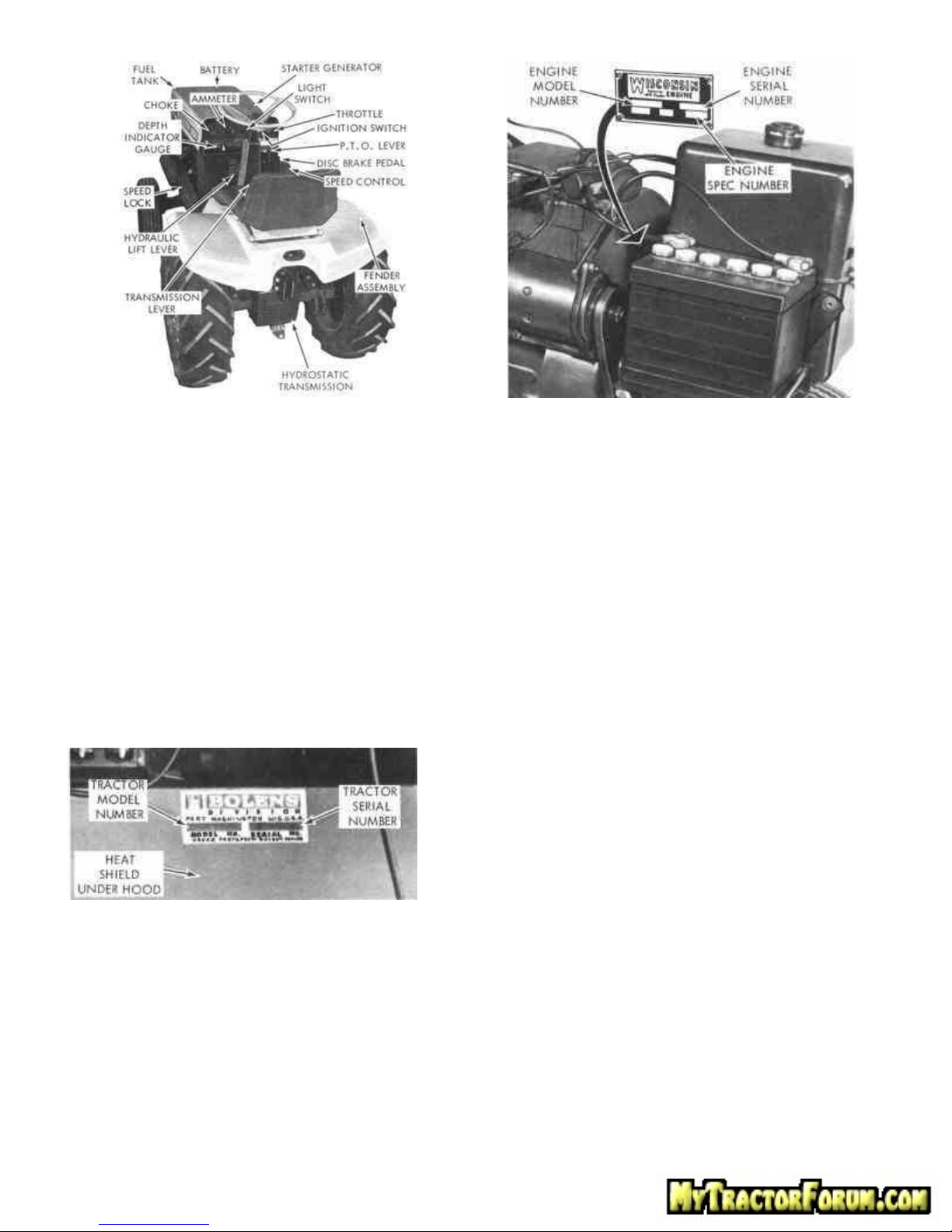
Figure 1 Figure 3
SERIAL NUMBER
To ensure prompt service when repairs or adjustments are
required, your Bolens Dealer must have the following
information:
1. Model number of unit.
2. Serial number of unit.
3. Model number of engine.
4. Serial and Spec. number of engine.
Your Bolens dealer has available a master Parts List for
your unit. He can identify any parts you may require and
furnish genuine factory replacements.
When ordering engine component parts, consult the
Engine Manufacturer's Manual.
For your own personal reference, fill in the spaces
provided below.
Model Number of Unit _______________________
Serial Number of Unit _______________________
Engine Model Number _______________________
Engine Serial Number _______________________
Engine Spec. Number _______________________
PAGE 2
SPECIFICATIONS
(Specifications subject to change without notice)
NOTE
Bolens reserves the right to make changes or
improvements to its products without obligation to install
same on products previously manufactured.
Engine 28.86 cu. inch Wisconsin
Type
Fuel capacity 5.3 gallons
Engine oil capacity 2 quarts
Transmission oil capacity
Air cleaner Dry type
Drive Hydrostatic transmission
Speed. Infinitely variable.
Power to attachments
Tires
Height 45 inches
Width 38 inches
Length 72 inches
Wheelbase 49 inches
Turning radius 54 inches
Ground clearance 8-1/2 inches
Shipping weight 975 lbs.
4 cycle, single cylinder, air
cooled
10 quarts
Forward: approx. 0-8 mph
Reverse: approx. 0-4 mph
Triple belt drive (P.T.O.), with
universal joints and splined
shaft.
Front: 5.70/5.00-8
Rear: See optional equipment
section, page 14.
Standard equipment. . P.T.O., splined shaft to drive
front, center or rear attachments, hydraulic lift system
with visual depth gauging, electric starting, head lights
and tail lights, full fenders, adjustable all angle seatspring suspension with foam-padded adjustable seat
(easily removable for weather protection), 45 amp
battery, selector level for drive-neutral-park, tapered
roller bearing front wheels and replaceable spindle
bushings, automotive type muffler, compression
release for easy starting, coil ignition, three-unit
regulator (automotive type), ammeter, extra heavy
channel frame, tilting hood for access to engine.
Location of tractor model and serial number . . . . . . .
Top left side of heat shield
Location of engine model and serial number . . . . . . . . .
Front of engine cowling
BREAK-IN PERIOD Figure 3
As with a new car, your new HUSKY Tractor should
receive special attention. During the first few hours of
operation, it is best to vary the engine speed (see
inside front cover of engine manual) . . . . . . avoid full-
throttle driving . . . . and avoid quick starts and stops
until you have become well acquainted with your
tractor. IMPORTANT: THE TRACTOR IS SHIPPED
FROM THE FACTORY WITH OIL IN THE ENGINE
CRANKCASE. CHECK THE CRANKCASE AND THE
HYDROSTATIC TRANSMISSION OIL RESERVOIR
FOR PROPER OIL LEVEL BEFORE ATTEMPTING TO
START YOUR UNIT. BECOME FAMILIAR WITH THE
LOCATION OF EACH CONTROL. BE SURE
TRANSMISSION LEVER IS IN "PARK" POSITION.
Both the tractor and engine have been fully tested by
the factory and your dealer to assure your complete
satisfaction. Keep this manual available at all times,
read it carefully, if you have any questions that are not
answered in the manual, consult your Bolens dealer.
CONTROLS
Before operating the tractor, the operator should
become familiar with the function and location of each
control to ensure proper and efficient operation.
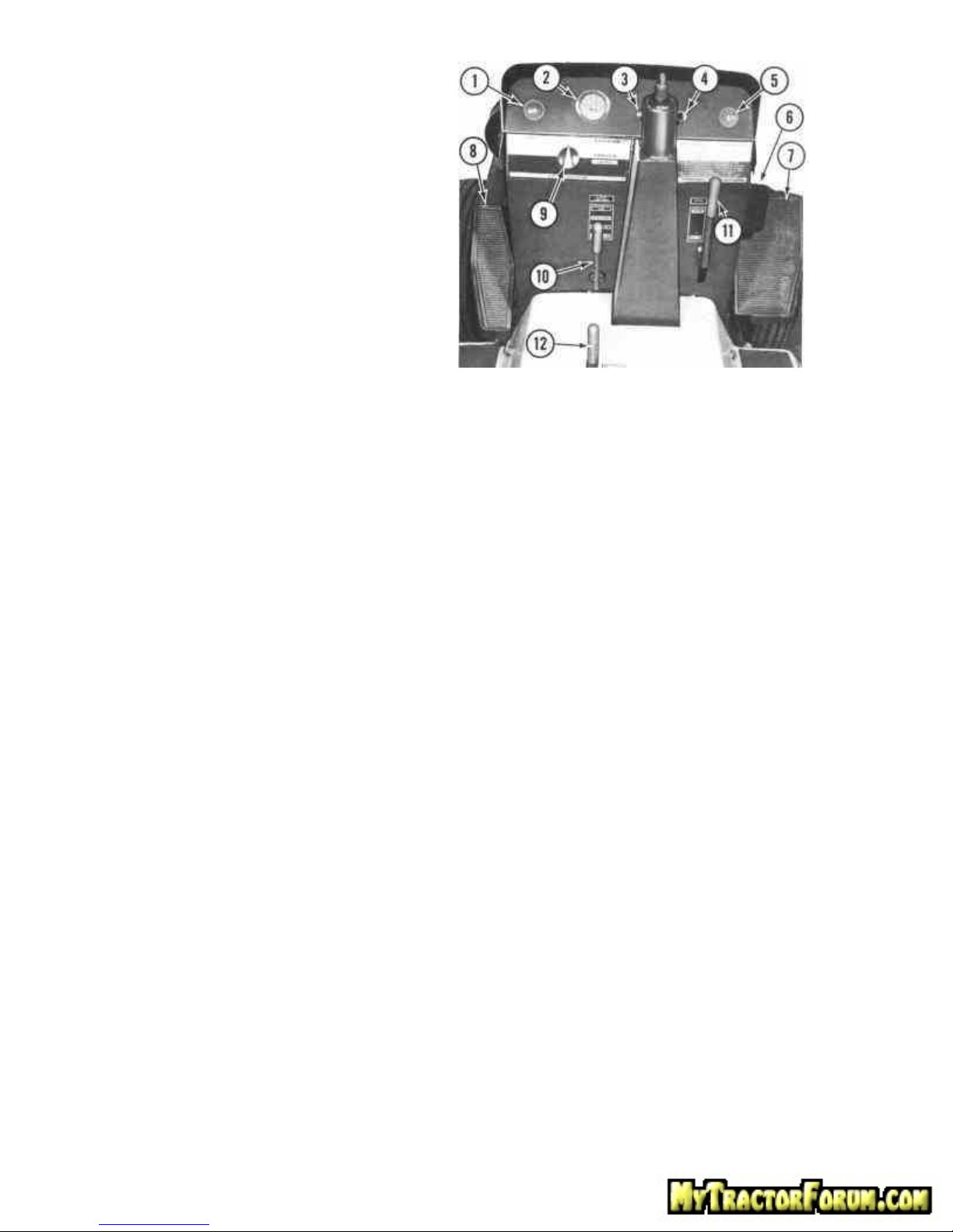
The following listed numbers and accompanying
information correspond to those numbers assigned to
the controls indicated in Figure 4.
1. Choke. Pull choke knob out to operate choke.
2. Ammeter. Indicates level of charge or discharge to or
from battery.
3. Light Switch. Pull light switch knob out to turn on
lights . . . . push in to turn lights off.
NOTE
Ignition-starter switch (4) must be ON to turn on head
and tail lights.
4. Ignition-Starter switch. Turn ignition switch against spring
tension to actuate starter. Release when engine starts.
5. Throttle. Pull throttle knob out one-half way for starting.
More or less throttle may be required due to grade of fuel and
temperature variations. Allow engine to warm up, then adjust
throttle to full engine R.P.M. while operating under load.
6. Foot Brake. Use when vehicle is being towed or freewheeling; when moving transmission lever (12) from
NEUTRAL or PARK position to DRIVE position.
7. Speed Control. Depress with toe of foot for forward motion.
Depress with heel of foot for reverse motion. Provides instant
braking and speed regulation. (See Figure 7.)
8. Speed Hold. Can be used to hold speed control (7) at a
desired speed setting. Depress with toe of left foot to hold,
and depress with heel of left foot to unlock. See Figure 6 for
operation of speed hold on page 5.
9. Depth Indicator Gauge. Allows operator to locate original
height or depth of attached implement.
10. Hydraulic Lift Lever. Push lever forward to raise and pull
lever back to lower attachments. Pull lift lever all the way back
for FLOAT position.
11. Power Take-Off (P.T.O.) Lever. Engages and disengages
power to attached implements. Lever positions indicated on
etched plate.
12. Transmission Lever. Place transmission lever in :
- NEUTRAL for towing .
- DRIVE for infinitely variable speeds from 0-8 mph forward
to 0-4 mph in reverse .
- PARK for starting and when tractor is At Rest.
CAUTION
Do not place transmission lever into PARK position while
tractor is in motion. Premature shifting into PARK may result
in serious damage to the hydrostatic transmission.
PAGE 3
PRE-OPERATIONAL CHECKS
EMERGENCY STARTING
The operator should become familiar with the following
pre-operational check list prior to starting or operating
the HUSKY.
1. Thoroughly clean area around crankcase oil dipstick,
and check for proper level of engine oil. See Engine
Manufacturer's Manual.
2. Thoroughly clean area around hydrostatic
transmission fill plug area, and check for proper level of
transmission fluid. See Lubrication Chart.
3. Check battery for proper water level.
4. Check gasoline tank for sufficient gas supply.
5. Check that air cleaner screen is free of debris. Check
and clean regularly. Replace if necessary.
6. Clean flywheel screen. Check and clean regularly.
7. Visually check for loose nuts and screws.
8. Check for 6-8 Ibs. tire inflation. TIRE INFLATION
SHOULD NOT BE LESS THAN 6 LBS.
In case of an electrical failure, proceed as follows:
1. Recharge or replace battery.
2. Jumper cables may be used. NOTE: If jumper cables are
used, cables must be connected, Positive (+) to Positive (+)
and Negative (-) to Negative (-).
3. After engine has started, allow it to warm up. Move choke
knob slowly forward, pull out throttle and lock at full speed.
4. Remove battery and have it fully charged as soon as
possible.
5. After the battery is fully charged, reinstall it in the tractor,
being careful to connect ground cable last.
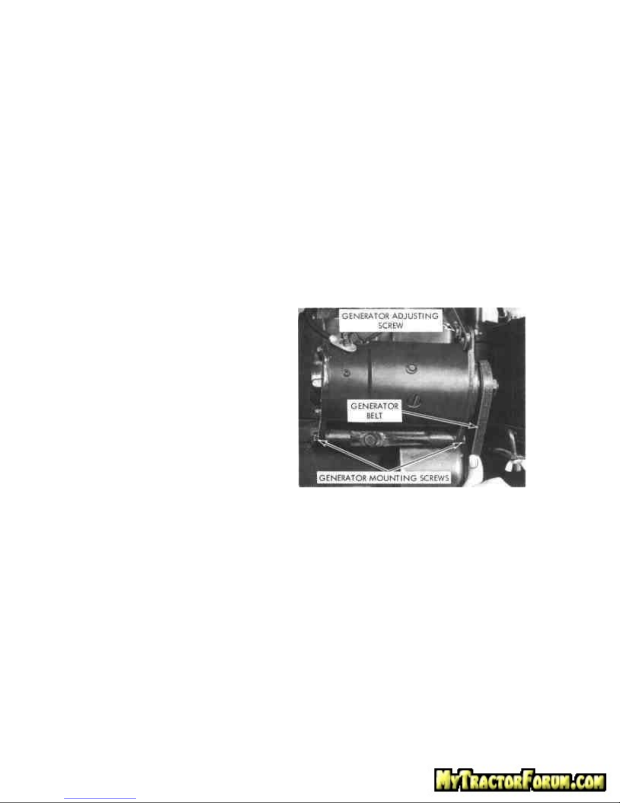
6. Check generator belt for proper tension. Belt should
depress 1/4 inch between pulleys as shown in Figure 5.
Should adjustment be required, loosen generator mounting
screws and generator adjusting screw. Pivot generator
outward from engine until proper tension is obtained.
9. Do not allow ignition switch to remain in the on
position when engine is not running.
STARTING THE ENGINE
ELECTRIC STARTING
1. Be sure power take-off (P.T.O.) safety clutch is in the
OFF position, and the transmission lever is in PARK
position.
2. Pull out choke. Experience will indicate need for
more or less choking due to temperature variations,
grade of fuel, engine heat, etc.
3. Pull out throttle one-half way. More or less throttle
may be required due to grade of fuel and temperature
variations.
4. Turn ignition key against spring tension to actuate
starter. Release key when engine starts.
5. Allow engine to warm up. Move choke slowly
forward; pull out throttle and lock at full speed while
operating.
6. To stop the engine, bring engine back to idle, place
transmission lever in PARK and turn ignition switch off.
Remove the ignition key when the tractor is not in use,
or left unattended.
Figure 5
NOTE
Never pry out generator with a long heavy bar or tool as this
could result in premature bearing failure.
7. Tighten the generator mounting screws and generator
adjusting screw. Make sure all bolts are torqued securely.
PAGE 4
 Loading...