

Page 1
STOCK NUMBER
93-7122.0
MODEl. NUMBER
MTO1122B09
FACTORY NUMBER
130..61OF098
Thank you tol' purchasing an Amel'lcan-built product.
Page 2

Slope Gauge Safe Operation Practices
Assembly Instructions. .
Controls.. "
Operation. Adjustments lubrication Maintenance Off-Season Storage.
Western Auto Supply Company warrants to the original retail purchaser that this Wizard product
is free from defects in material and workmanship and agrees to repair any product free of charge
within these time periods from date of purchase:
One year, if the product is used for personal, family, or household use;
90 days, if the product is used for any other purpose such as commercial or rental use.
A battery which proves defective within ninety (90) days will be replaced without charge. After
90 days but within one year from the date of purchase. Western Auto will replace the defective
battery for a charge of 1/12 of the current retail price of the battery for each full 30 day period
between the date of purchase and the date of return.
The company manufacturing the engine furnishes their own two year warranty and provides service through their authorized field service facilities. For additional information, see the warranty
covering the engine. Repair service arrangements may be handfed through any participating
Western Auto Store.
Excluded from this warranty are: normal wear and maintenance, and mechanical adjustments which
are not due to defects in material or workmanship. For assistance in making such adjustments,
consult your owner's manual. Any unit which has been altered, misused, abused, or repaired by
other than a Western Auto authorized service facility is also excluded.
For repair service return unit with proof of purchase date to any participating Western Auto Store.
If difficulty is encountered in having this warranty honored, contact: Western Auto Supply Company, Consumer Affairs Section, General Service Department, 2107 Grand Avenue, Kansas City,
Missouri 64108. This warranty gives you specific legal rights, and you may also have other rights
which vary from state to state.
.3
.5
.6
Engine Operating and Maintenance
Instructions. Trouble Shooting Chart. Illustrated Parts for Lawn Tractor. .
10
Electrical System. Illustrated Parts for Transaxle Illustrated Parts for Engine. Partslnformation
12
14
15
18
MTD7122BO9
LIMITED WARRANTY
19-23
,.. .24.25
26-33
..., ...29
34,35
36-39
Back Cover
WARNING: This unit is equipped with an internal combustion engine and should not be used on or near any unim-
proved forest-covered, brush-covered or grass-covered land unless the engine's exhaust system is equipped with
a spark arrester meeting applicable local or state laws (if any). If a spark arrester is used, it should be maintained
in effective working order by the operator.
In the State of California the above is required by law (Section 4442 of the California Public Resources Code).
Other states may have similar laws. Federal laws apply on federal lands. A spark arrester for the muffler is available
through participating Western Auto Stores.
2
Page 3
E~ 't: .-
0;o.~-u <
a.-C
~c: -c
>~
cE.
.
> u
41 ~
41 c:
...
4I.c
-I/)
.
.
-I/)
.
.
.
.
.
.
.
.
41 -
41 41
-Q.
-:. .-=
-
< .~
.
.
.
.
.
.
.
.
~N ...>
.! 0 .
"".
Q.:
-~ GI ...
o.
('II ~ .:. .
.../'
>OC: ~
Cf):
m"iOl ~"U
GlE~ Q.
E c: .2 ~
00)1/) ~~
Q.-9c: 00
-'- 0)
';-c:J ~
a. oX'- _"a
"x .c 0) ~ C
0>:;: Om
0)~3 GlQ.
~OII/) ~:J
c", "~.: ~ --GI
Z ~GI=-O)
Z -~.GI>
a: GlQ.1/) ~c:
< ~°"U ~rh
In
0
0 .
>- OI=:- eGi
-
-c .0 ~ 0
~ GI ~uQ.
>1.) -
0 GI-
o,S>~O
Ln~~"'~
~"U CO)
~~c C~
~ ~
"'- --J
EO) 0)0)
~ GI'-
Eo~a::~
001 ~~
- E --
cc~ "-:; GI 0)
o~x a.Q.
0 .~ GI 0 0
~
r7
c81.) ~..:.,
0 ~ ZoA.
~:Jc :J
.~ a. 0
.c c:"jU ~ ~
c3--= EUJ
~O) E ... 00» 41
,
.-:J m
u-c- O~
.: 0 0 ~ ~
,
,
,
,
-~
I/)~c: -I.)
I/)o~ ~~
GI .-GI -
CO)O ~
O):J- ~O
~~OI Q.GI
GI ~.S ~ £
\
.
0 I.) ~ I.)
a.~... 0"-
"- ~ 0 C ~
~c>-U1/)
--uo"am
II ..
~I ..i I
I
.~
i >
I ..J
I W
, u.
c:(
U')
I W
I ..-
I c:(
I a:
j
, ,
, '
I'",
, I ~ j
I~
..
.
.
.
.
.
1 , .
I ..-
I ..
I .
I ..
I.. ,
I W
I W
I: b Y)
I U')
I -
I :I:
I U')
+ i~~!ff ;~)1 ~
W
U')
I
I :J
I
I :I:
I ..-
I
I
I
I
.
---
I .,
:
I «
I
W tn.
W -.'
w '" .
ct ct Q.:
ct ~ a.. ~:
[I: ~ -.
(.) 0 UJ J ~ ::! (.) $.:
~ C/) '..
-J ~ 0 c.
[I: => Z
UJ ID ",,'
> ~ cr'
< ~ ",,'
I 0 ~ tt::
z I -.
~ a: .'
3 UJ I ~:
-J a:, .../.
~ LIJ 0 I fi1:
T J (/) Cl. I 0:
T . C/) .
I .
I I .
I :--
-J <:> ct
-CI: c.
w .OJ U I J... :
~ w I ~: "> I c;..
0 :> I o.
Z I I :
-J 0 I C:
0 Cl. .../.
::I: .~ I 0:
Q I L4.:.
<-' I I :
< I I :
I- I I .
:I: I I :
I I .
-I
r': ~'; '
I I :
I I .
cn
10
I ..-
: Z
I >
I «
I ~
I
I =>
10
I >
I UJ
I a:
I UJ
~ :s:
41
I :I:
.S U')
-J W
.~ Q.
oC 0
~-.. ..J
c:t W
I a:
:J -
-Z
Y ~
I C
10
I ..-
I
I W
I C
I -
I w
I t-
I UJ
I =>
I cn
I "
I «
I w
I Q.
10
Page 4
I
I
I
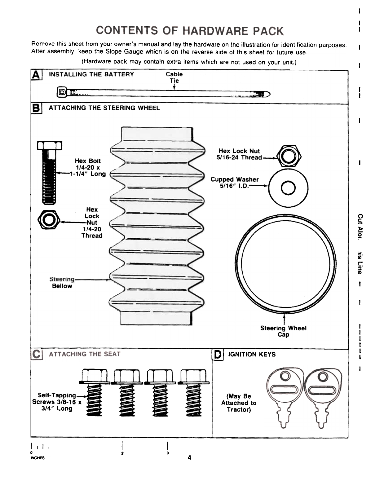
Remove this sheet from your owner's manual and lay the hardware on the illustration for identification purposes.
After assembly, keep the Slope Gauge which is on the reverse side of this sheet for future use.
(Hardware pack may contain extra items which are not used on your unit.)
INST ALLING THE SA TTERY Cable
Tie
rf§:!;~--- + ~~
A TT ACHING THE STEERING WHEEL
Hex Lock Nut
5/16-24 c
Hex Bolt
1/4-20 x
.Long
Hex
@ ~ Lock
Nut
1/4-20
Thread
I
I
I
I
I
I
CO)
c
-
:!:
2
Bellow
Screws 3/8-16 x
3/4" Long
Steering Wheel
1m IGNITION KEYS
(May Be
Attached to
Tractor)
Cap
~
in"
!::
~
CD
I
I
I
I
I
I
I
I
I
I I I I
0
I«;tES
I
2
I
3
4
Page 5
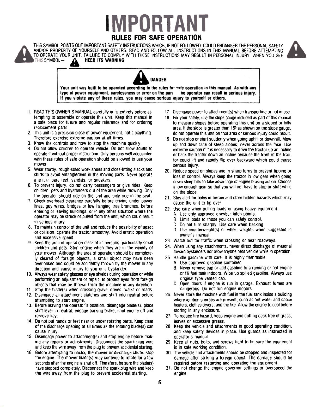
RULES FOR SAFE OPERA liON
THIS SYMBOL POINTS OUT IMPORTANT SAFETY INSTRUCTIONS WHICH, IF NOT FOLLOWEO COULD ENDANGER THE PERSONAL SAFETY
AND/OR PROPERlY OF YOURSELF AND OTHERS READ AND FOLLOW ALL INSTRUCTIONS IN THIS MANUAL BEFORE ATTEMPTING
TO OPERATE YOUR UNIT FAILURE TO COMPl Y WITH THESE INSTRUCTIONS MAY RESULT IN PERSONAL INJURY WHEN YOU SEE
SYMBOl- A HEED ITS WARNING.
1 READ THIS OWNER'S MANUAL carefully in Its entirety before at-
temptIng to assemble or operate this unit. Keep this manual In
a safe place for future and regular reference and for ordering
replacement par1s.
2. This unit is a precision piece of power equipment. not a plaything.
Therefore exercise extreme caution at all times
3 Know the ccntrols and how to stop the machine QuIckly
4 Do not allow children to operate vehicle. Do not allow adults to
operate it without proper Instruction. Only persons well acquainted
with these rules of safe operation should be allowed to use your
mower
5. Wear sturdy, rough-soled work shoes and close-fitting slacks and
shirts to avoid entanglement in the moving pans. Never operate
a unit in bar~ feet, sandals, or sneakers.
6. To prevent inJury, do not carry passengers or give rides. Keep
children, pet~i and bystanders out of the area while mowing. Only
the operator should ride on the unit and only ride in the seat
7 Check overhead clearanc~ c-arefully before driving under power
lines. guy wires, brIdges or low hanging tree branches, before
entering or leaving buildings. or in any other situation where the
operator may be struck or pulled from the unit, which could result
in serious injury
8. To maintain control of the unit and reduce the possibility of upset
or collision. cperate the tractor smoothly Avoid erratic operation
and excessive speed.
9. Keep the area of operation clear of all persons, particularly sl:1all
children and pets Stop engine when they are in the vicinity of
your mower Although the area of operation should be completely cleared of foreign objects, a small obJect may have been
overlooked and could be accidently thrown by the mower in any
direction and cause inJury to you or a bystander.
10. Always wear ~~afety glasses or eye shields during operation or while
performing art adlustment or repair. to protect eyes from foreign
objects that rnay be thrown from the machine in any direction
11. Stop the blaOe(s) when crossing gravel drives, walks or roads
12. Disengage all attachment clutches and shift into neutral before
attempting to start engine.
13. Before leaving the operator's position. disengage blade(sj, place
shift lever in leutral, engage parking brake. shut engine off and
remove key.
14 Do not put hands or feet near or under rotating parts. Keep clear
of (he discharge opening at all times as the rotating blade(s) can
calise Inlury.
15. Disengage poller to attachment(s) and stop engine before making any repairs or adjustments Disconnect the spark plug wire
and keep the wire away from the plug to prevent accidental starting.
16. Before atteml:,ting to unclog the mower or discharge chute, stop
the engine. The mower blade(s) may continue to rotate for a few
seconds after ~he engine is shut off. Therefore, be sure the blade(s)
ha~e stopped I~ompletely. [)sconnect the spark plug wire and keep
the wire away from the plug to prevent accidental starting
17 Disengage power to attachment(s) when transporting or not In use
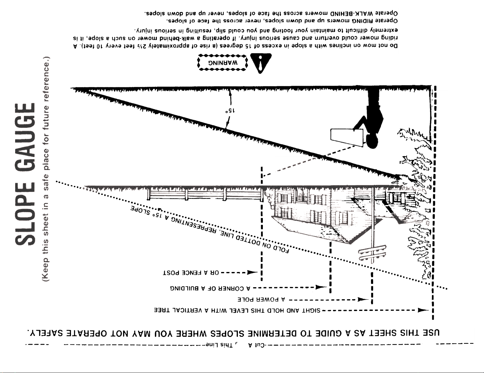
18. For your safety, use the slope gau~ Included as part of thiS manual
to measure slopes before operating this unit on a sloped or hilly
area. If the slope is greater than 150 as shown on the slope gauge.
do not operate this unit on that area or serious injury could result.
19. Do not stop or start suddenly when going uphill or downhill. Mow
up and down face of steep slopes; never across the face Use
extreme caution if it IS necessary to drive the tractor up an incline
or back the tractor down an Incline because ttle front of the trac-
tor could lift and rapidly flip over backward which could cause
serious injury
20. Reduce speed on slopes and in sharp turns 10 prevent tipping or
loss of control. Always keep the tractor in low gear when gOing
down steep hills to take advantage of engine braking action Choose
a low enough gear so that you will not have to stop or shift while
on the slope
21. Stay aler1 for roles in terrain and other hidden hazards which may
cause the unit to tip over
22 Use care when pulling loads or uSing heavy equipment.
A Use only approved drawbar hitch points.
B Limit loads to those you can safely control.
C. Do not turn sharply. Use care when backing.
0 Use counterweight(s) or wheel weights when suggested in
owner's manual.
23. Watch out for traffic when crossing or near roadways.
24. When using any attachments, never direct discharge of material
toward bystanders nor allow anyone near vehlc~ while In operation.
25 Handle gasoline with care It is highly flammable
A Use approved gasoline container
B. Never remove cap or add gasoline to a running or hot engine
or fill fuel tank indoors Wipe up spilled gasoline Always use
original type vented cap.
C Open doors if engine is run in garage. Exhaust fumes are
dangerous Do not run engine indoors
26. Never store the machine with fuel in the fuel tank inside a building
where ignition sources are present. such as hot water and space
heaters. clothes dryers, and the like. Allow the engine to cool before
storing in any enclosure.
27 To reduce fire hazard, keep engine and cutting deck free of grass,
leaves or excessive grease
28 Keep the vehicle and atlCM:hments in good ~erating condition.
and keep safety devices in place. Use guards as instructed In
operator's manual.
29 Keep all nuts, bolts. and screws tight to be sure the eQuipment
is in safe working condition.
30. The vehicle and attachments should be stopped and inspected for
damage after striking a foreign object. The damage should be
repaired before restarting and operating the eQuipment
31. Do not change the engine governor settings or overspeed the
engine.
5
,
~
Page 6
32. When using the vehicle with roower, proceed as follows: 34. Look behind to make sure the area IS clear before placing the
(1) Mow only in daylight or in good artificial light transmission in reverse and continue lookIng behInd while back-
(2) Never make a cutting heIght a~ustment while engine IS running ing up Disengage blades before shifting into reverse and backing
if operator must dismount to do so up.
(3) Shut the engine off and walt until the blade comes to a complete 35. This unit should not be driven up a ramp onto a trailer or truck
stop before removing the grass catcher. under power. because the unit could tip over, causIng serious per-
(4) Check blade roounting bolts for proper tightness at frequent in- sonal injury. The unit must be pushed manually to load properly
tervals. 36. Check brake operation frequently. Adjust and service according
33. Check grass catcher bags frequently for wear or deterioration. For to brake adjustment "structions in this manual
safety protection. replace ooly with new bag m~ting original equipment specifications.
ASSEMBLY
IMPORTANT: This unit is shipped WITHOUT
GASOLINE or OIL; however, a small amount of oil
may be present from the factory. Do not overfill.
After assembly, service engine with gasoline and
oil as instructed in the engine section of this
manual.
NOTE: Reference to right or left hand side of the
unit is observed from the driver's seat, facing
forward.
UNPACKING
1. Remove the lawn tractor from the carton as follows.
Open the top flaps. Remove all loose parts and carton inserts. Cut the front corners of the carton.
Make certain brake is released. and push the unit
out of the carton.
2. Remove page four from this manual and lay the
contents of the hardware pack on the illustration
for identification.
BATTERY INFORMATION
A WARNING
A. Battery acid must be handled with great care as
contact with it can burn and blister the skin. It is also
advisable to wear protective clothing (goggles, rub-
ber gloves and apron) when working with it..
B. Should battery acid accidentally splatter into the
eyes or onto the face, rinse the affected area im-
mediately with clean cold water. If there is any
further discomfort, seek prompt medical attention.
C. If acid spills on clothing, first dilute it with clean
water, then neutralize with a solution of ammonia}
water or baking soda/water.
D. Since battery acid is corrosive, do not pour it into
any sink or drain. Before discarding empty elec-
trolyte containers. rinse them with a neutralizing
solution.
E. NEVER connect or disconnect charger clips to bat-
tery while charger is turned on as it can cause
sparks.
F. Keep all lighted materials (cigarettes, matches,
lighters) away from the battery as the hydrogen gas
generated during charging can be combustible.
G. As a further precaution, only charge the battery in
a well-ventilated area.
.Always shield eyes, protect skin and clothing
when working near batteries.
6
Page 7
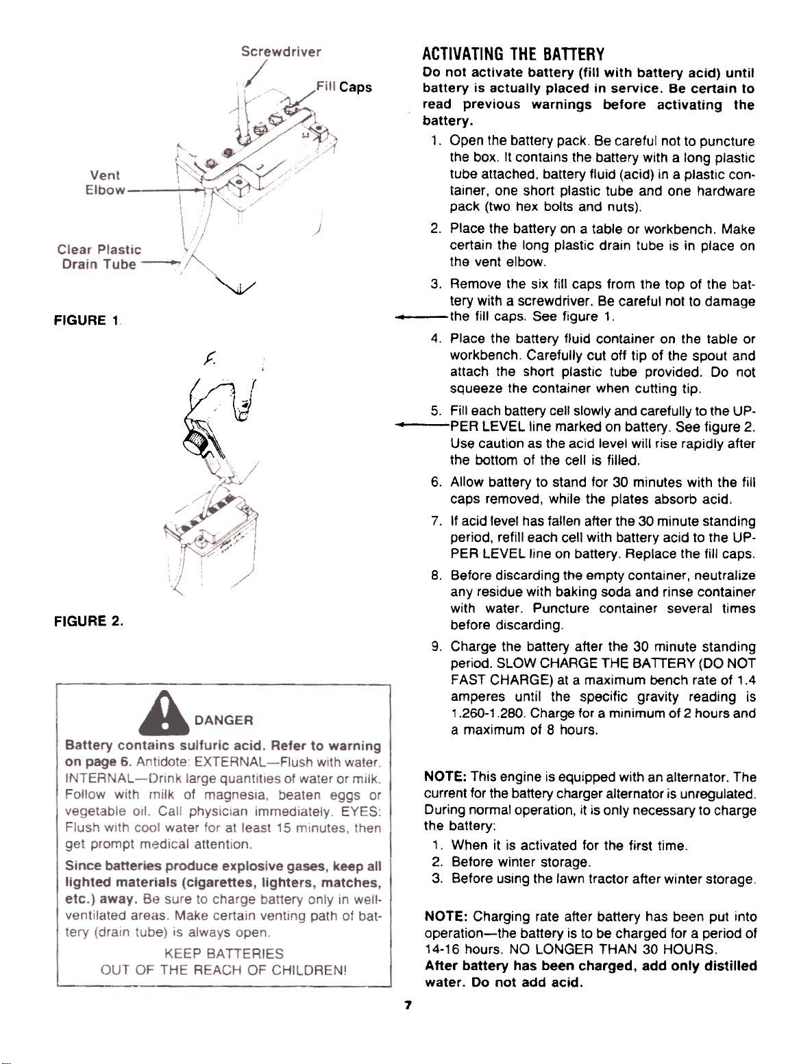
FIGURE 1,
FIGURE 2.
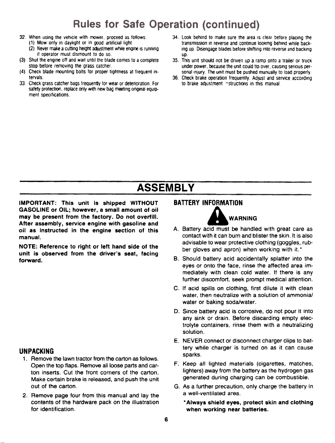
ACTIVATING THE BATTERY
Do not activate battery (fill with battery acid) until
Caps
"
~
battery is actually placed in service. Be certain to
read previous warnings before activating the
battery.
1. Open the battery pack. Be careful not to puncture
the box. It contains the battery with a long plastic
tube attached, battery fluid (acid) in a plastic container, one short plastic tube and one hardware
pack (two hex bolts and nuts).
2. Place the battery on a table or workbench. Make
certain the long plastic drain tube is in place on
the vent elbow.
3. Remove the six fill caps from the top of the battery with a screwdriver. Be careful not to damage
4 the fill caps. See figure 1.
4. Place the battery fluid container on the table or
workbench. Carefully cut off tip of the spout and
attach the short plastic tube provided. Do not
squeeze the container when cutting tip.
5. Fill each battery cell slowly and carefully to the UP.
.PER LEVEL line marked on battery. See figure 2.
Use caution as the acid level will rise rapidly after
the bottom of the cell is filled.
6. Allow battery to stand for 30 minutes with the fill
caps removed, while the plates absorb acid.
7. If acid level has fallen after the 30 minute standing
period, refill each cell with battery acid to the UP-
PER LEVEL line on battery. Replace the fill caps.
8. Before discarding the empty container, neutralize
any residue with baking soda and rinse container
with water. Puncture container several times
before discarding.
9. Charge the battery after the 30 minute standing
period. SLOW CHARGE THE BATTERY (DO NOT
FAST CHARGE) at a maximum bench rate of 1.4
amperes until the specific gravity reading is
1.260-1.280. Charge for a minimum of 2 hours and
a maximum of 8 hours.
,f.
~
NOTE: This engine is equipped with an alternator. The
current for the battery charger alternator is unregulated.
During normal operation, it is only necessary to charge
the battery:
1. When it is activated for the first time.
2. Before winter storage.
3. Before using the lawn tractor after winter storage.
NOTE: Charging rate after battery has been put into
operation-the battery is to be charged for a period of
14-16 hours. NO LONGER THAN 30 HOURS.
After battery has been charged, add only distilled
water. Do not add acid.
7
Page 8
Battery
~Drain
Tube
FIGURE 3.
,I
I~
=~~~
..! r- --.,,-
\y Terminal
~
-'- --
Black Box Red
(Negative) (Positive)
Cable Cable
Battery -\
Negative
/ Positive
\'9
INSTALLING THE BATTERY (Hardware A)
1. Raise the seat bracket (on top of the fenders).
2. Make certain the positive cable (heavy red wire)
extends through the retainer on the front of the battery box. The negative cable (heavy black wire)
should be routed up along the back of the battery
box.
3. Place the battery inside the battery box so that the
positive terminal is toward the front of the unit. See
figure 3. Route the battery drain tube down beside
the battery box.
4". Slide the hex nut (provided with battery hardware)
into the positive (+) terminal. Place the positive
cable on the positive terminal. Secure with bolt pro--'vided.
See figure 3.
5. Slide the hex nut (provided with battery hardware)
into the negative (-) terminal. Place the negative
cable on the negative terminal. Secure with bolt
provided.
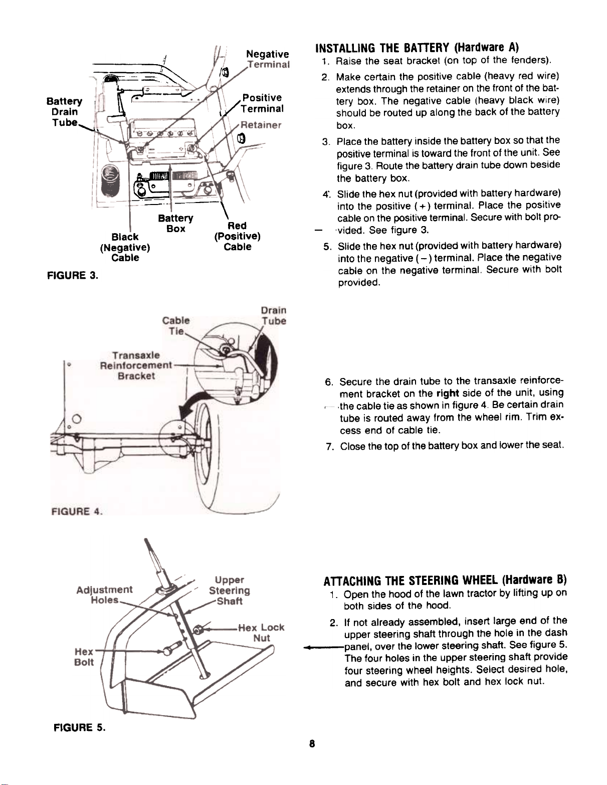
6. Secure the drain tube to the transaxle reinforcement bracket on the right side of the unit, using
~ .the cable tie as shown in figure 4. Be certain drain
tube is routed away from the wheel rim. Trim excess end of cable tie.
7. Close the top of the battery box and lower the seat.
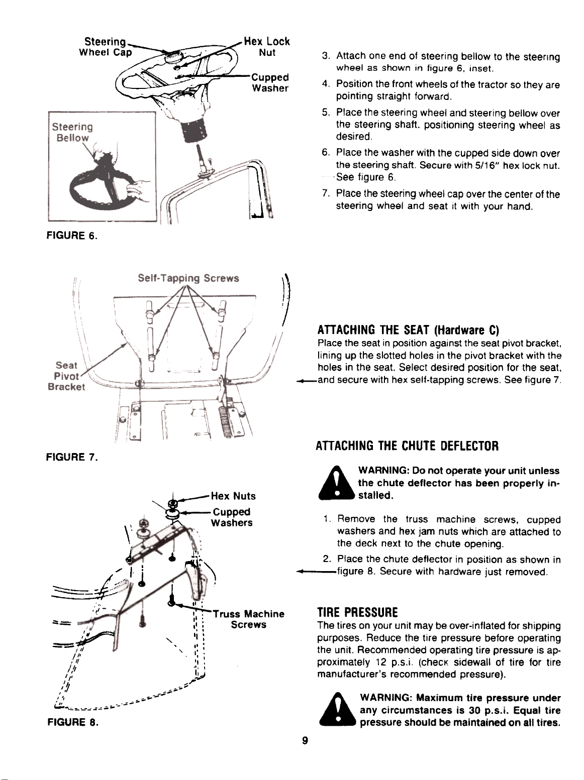
ATTACHING THE STEERING WHEEL (Hardware B)
1. Open the hood of the lawn tractor by lifting up on
both sides of the hood.
2. If not already assembled, insert large end of the
upper steering shaft through the hole in the dash
.panel, over the lower steering shaft. See figure 5.
The four holes in the upper steering shaft provide
four steering wheel heights. Select desired hole,
and secure with hex bolt and hex lock nut.
FIGURE 5.
8
Page 9
Steeri
FIGURE 6.
~~~HeX Lock Wheel ,~ Nut
,
..,r"
:--- Cupped
Washer
-"'l\
.J\
3. Attach one end of steering bellow to the steering
wheel as shown in figure 6, inset.
4. Position the front wheels of the tractor so they are
pointing straight forward.
5. Place the steering wheel and steering bellow over
the steering shaft. positioning steering wheel as
desired.
6. Place the washer with the cupped side down over
the steering shaft. Secure with 5/16" hex lock nut.
~ See figure 6.
7. Place the steering wheel cap over the center of the
steering wheel and seat it with your hand.
ATTACHING THE SEAT (Hardware C)
Place the seat in position against the seat pivot bracket,
lining up the slotted holes in the pivot bracket with the
holes in the seat. Select desired position for the seat,
_and secure with hex self-tapping screws. See figure 7.
FIGURE 7.
\"
J
/, i
/- .:.-
k .. II '
----
--= ' ,.'
-III " ,':
/. ~ '
, --
, " -..~
c:.::.~:,,-," =-, ;';"
FIGURE 8.
:~I .:-~
~,=.. ~ I
, "I
1/1 I ,
, /1 'I ,
1/1 do ,
/, II -1
/" ,..,
7 -,,--
, --
-..;--
Hex Nuts
Cupped
.Washers
r\l~)
:1; Truss Machine
,I : Screws
I':
AnACHING THE CHUTE DEFLECTOR
A WARNING: Do not operate your unit unless
the chute deflector has been properly installed.
1. Remove the truss machine screws. cupped
washers and hex jam nuts which are attached to
the deck next to the chute opening.
2. Place the chute deflector in position as shown in
~ figure 8. Secure with hardware just removed.
TIRE PRESSURE
The tires on your unit may be over-inflated for shipping
purposes. Reduce the tire pressure before operating
the unit. Recommended operating tire pressure is ap-
proximately 12 p.s.i. (checK sidewall of tire for tire
manufacturer's recommended pressure).
A WARNING: Maximum tire pressure under
any circumstances is 30 p.s.i. Equal tire
pressure should be maintained on all tires.
~
~
.
~~
9
Page 10
CONTROLS
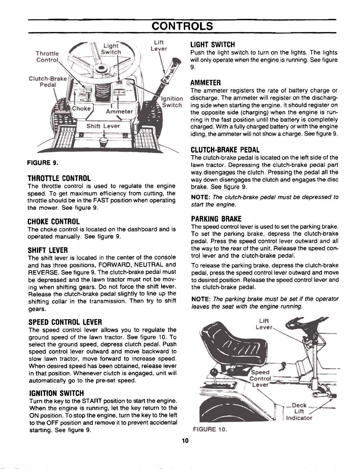
FIGURE 9.
THROTTLE CONTROL
The throttle control is used to regulate the engine
speed. To get maximum efficiency from cutting, the
throttle should be in the FAST position when operating
the mower. See figure 9.
LIGHT SWITCH
Push the light switch to turn on the lights. The lights
will only operate when the engine is running. See figure
9.
AMMETER
The ammeter registers the rate of battery charge or
discharge. The ammeter will register on the discharg-
ing side when starting the engine. It should register on
the opposite side (charging) when the engine is run-
ning in the fast position until the battery is completely
charged. With a fully charged battery or with the engine
idling, the ammeter will not show a charge. See figure 9.
CLUTCH-BRAKE PEDAL
The clutch-brake pedal is located on the left side of the
lawn tractor. Depressing the clutch-brake pedal part
way disengages the clutch. Pressing the pedal all the
way down disengages the clutch and engages the disc
brake. See figure 9.
NOTE: The clutch-brake pedal must be depressed to
start the engine.
CHOKE CONTROL
The choke control is located on the dashboard and is
operated manually. See figure 9.
SHIFT LEVER
The shift lever is located in the center of the console
and has three positions, FORWARD, NEUTRAL and
REVERSE. See figure 9. The clutch-brake pedal must
be depressed and the lawn tractor must not be mov-
ing when shifting gears. Do not force the shift lever.
Release the clutch-brake pedal slightly to line up the
shifting collar in the transmission. Then try to shift
gears.
SPEED CONTROL LEVER
The speed control lever allows you to regulate the
ground speed of the lawn tractor. See figure 10. To
select the ground speed, depress clutch pedal. Push
speed control lever outward and move backward to
slow lawn tractor, move forward to increase speed.
When desired speed has been obtained, release lever
in that position. Whenever clutch is engaged, unit will
automatically go to the pre-set speed.
IGNITION SWITCH
Turn the key to the START position to start the engine.
When the engine is running, let the key return to the
ON position. To stop the engine, turn the key to the left
to the OFF position and remove it to prevent accidental
starting. See figure 9.
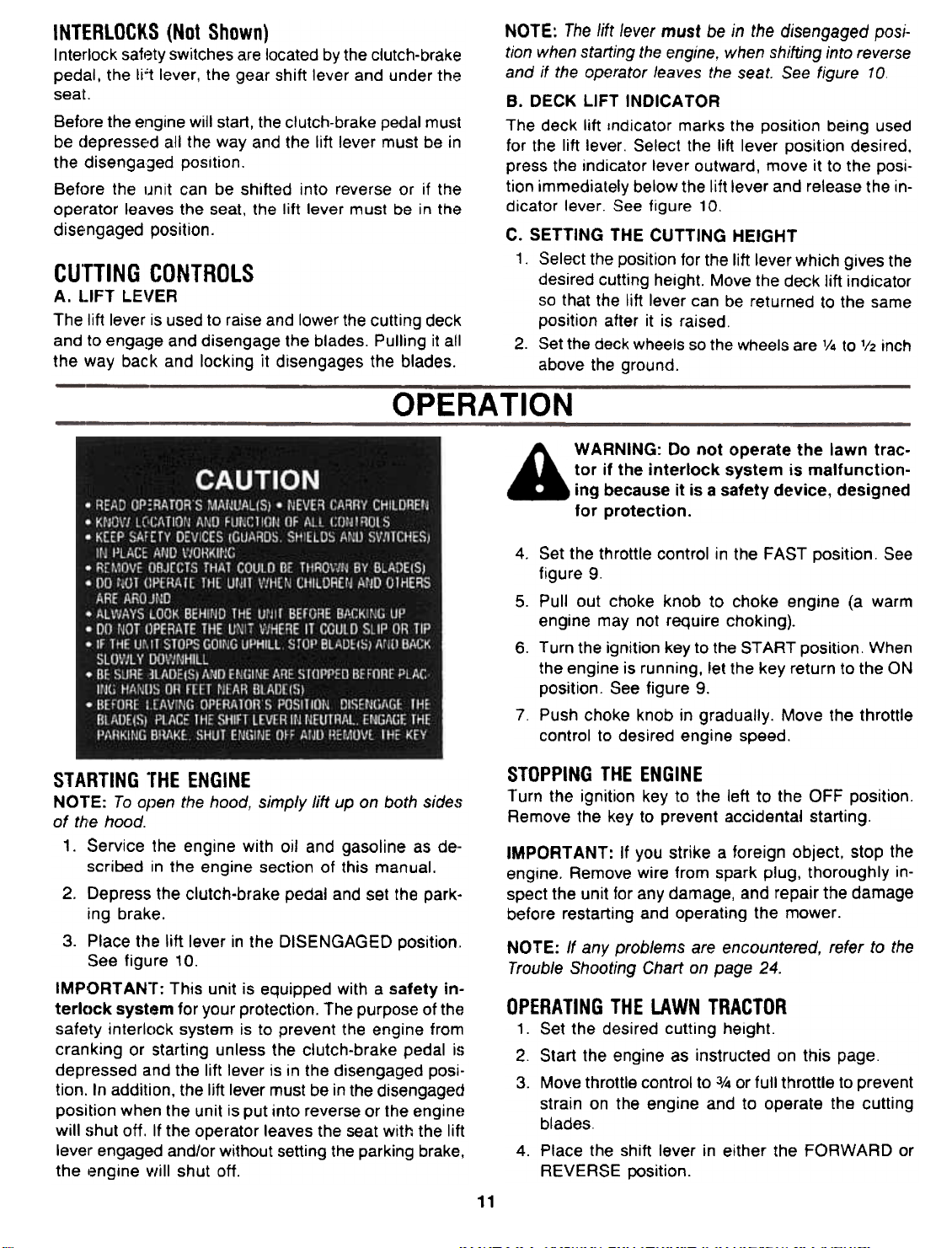
PARKING BRAKE
The speed control lever is used to set the parking brake.
To set the parking brake, depress the clutch-brake
pedal. Press the speed control lever outward and all
the way to the rear of the unit. Release the speed control lever and the clutch-brake pedal.
To release the parking brake, depress the clutch-brake
pedal. press the speed control lever outward and move
to desired position. Release the speed control lever and
the clutch-brake pedal.
NOTE: The parking brake must be set if the operator
leaves the seat with the engine running.
10
Page 11
INTERLOCKS (Not Shown)
Interlock safety switches are located by the clutch-brake
pedal. the li"t lever, the gear shift lever and under the
seat.
Before the engine will start, the clutch-brake pedal must
be (jepressed all the way and the lift lever must be in
the disengaged position.
Before the IJnit can be shifted into reverse or if the
operator leaves the seat, the lift lever must be in the
disengaged position.
CUTTING CONTROLS
A. LIFT LE"ER
The lift lever is used to raise and lower the cutting deck
and to engage and disengage the blades. Pulling it all
the way back and locking it disengages the blades.
OPERA TION
NOTE: The lift lever must be in the disengaged posi-
tion when starting the engine, when shifting into reverse
and if the operator leaves the seat. See figure 10
B. DECK LIFT INDICA TOR
The deck lift ,ndicator marks the position being used
for the lift lever. Select the lift lever position desired.
press the indicator lever outward, move it to the position immediately below the lift lever and release the in-
dicator lever. See figure 10.
C. SETTING THE CUTTING HEIGHT
1. Select the position for the lift lever which gives the
desired cutting height. Move the deck lift indicator
so that the lift lever can be returned to the same
position after it is raised.
2. Set the deck wheels so the wheels are '/4 to '/2 inch
above the ground.
WARNING: Do not operate the lawn tractor if the interlock system is malfunctioning because it is a safety device, designed
for protection.
STARTING "rHE ENGINE
NOTE: To open the hood, simply lift up on both s;de~;
of th'e hood.
1. Service the engine with oil and gasoline as de..
scribed in the engine section of this manual.
2. Depress the clutch-brake pedal and set the parking brake.
3. Place the lift lever in the DISENGAGED position..
See figure 10.
IMPORTANT: This unit is equipped with a safety in-
terlock system for your protection. The purpose of the
safety interlock system is to prevent the engine from
cranking or starting unless the clutch-brake pedal is
depressed and the lift lever is in the disengaged position. In addition, the lift lever must be in the disengaged
position when the unit is put into reverse or the engine
will ~)hut off. If the operator leaves the seat with the lift
lever engaged and/or without setting the parking brake.
the engine viii I shut off.
Set the throttle control in the FAST position. See
figure 9.
5. Pullout choke knob to choke engine (a warm
engine may not require choking).6.
Turn the ignition key to the START position. When
the engine is running, let the key return to the ON
position. See figure 9.
7 Push choke knob in gradually. Move the throttle
control to desired engine speed.
STOPPING THE ENGINE
Turn the ignition key to the left to the OFF position.
Remove the key to prevent accidental starting.
IMPORT ANT: If you strike a foreign object, stop theengine.
Remove wire from spark plug, thoroughly in-
spect the unit for any damage, and repair the damage
before restarting and operating the mower.
NOTE: If any problems are encountered, refer to the
Trouble Shooting Chart on page 24.
OPERATING THE LAWN TRACTOR
1. Set the desired cutting height.
2. Start the engine as instructed on this page.
3. Move throttle control to 3/4 or full throttle to prevent
strain on the engine and to operate the cutting
blades.
4. Place the shift lever in either the FORWARD or
REVERSE position.
4.
11
Page 12
WARNING: Look to the rear before back-
ing up.
5. Release the parking brake by depressing the
clutch-brake pedal, pressing outward on the speed
control lever and moving to desired position. Use
first speed position when operating the lawn trac-
tor for the first time.
6. Release clutch-brake pedal slowly to put unit into
motion.
7. The lawn tractor is brought to a stop by depressing the clutch-brake pedal.
NOTE: When operating the unit initially, there will be little
difference between the highest two speeds until after
the belts have seated themselves i~to the pulleys during the break.in period.
Move the lift lever into the DISENGAGED position to
raise the deck and disengage the blades.
GRASS CATCHER Stock Number 95-1136-1 (Factory
No. 190-064) is available as optional equipment.
A WARNING: The mower should not be
operated without the entire grass catcher
or chute deflector in place.
NOTE: Under normal usage bag material is subject to
wear, and should be checked periodically. Be sure any
replacement bag complies with the mower manufacturer's recommendations.
For replacement bags, use only factory authorized
replacement bag.
Be sure that the lawn is clear of stones, sticks, wire,
or other objects which could damage lawn mower or
engine. For best results and to insure more even grass
distribution, do not mow when lawn is excessively wet.
A WARNING: Before leaving the operator's
position for any reason, disengage the
blades, place the shift lever in neutral,
engage the parking brake, shut engine off
and remove the key.
When stopping the unit to empty a grass bag, etc.,
follow the instructions above. This procedure will also
eliminate "browning" the grass, which is caused by hot
exhaust gases from a running engine.
If unit stalls with speed control in high speed, or if unitwill
not operate with speed control lever in a low speedposition,
proceed as follows.
1. Place shift lever in NEUTRAL.
2. Restart engine.
3. Place speed control lever in high speed position.
4. Release clutch-brake pedal fully.
5. Depress clutch-brake pedal.
6. Place speed control lever in desired position.
7. Place shift lever in either FORWARD or
REVERSE, and follow normal operating pro-
cedures.
SEAT ADJUSTMENT
The seat may be adjusted to different positions. Refer
to seat installation section of assembly instructions.
STEERING WHEEL ADJUSTMENT
There are four height positions for the steering wheel.
To adjust the height of the steering wheel, remove the
hex bolt and hex lock nut on the steering shaft. Place
the steering wheel in the position desired and secure
with hex bolt and hex lock nut. Refer to figure 5.
NOTE: When raising the height of the steering wheel,stretch
the steering bellow to cover the steering shaft.
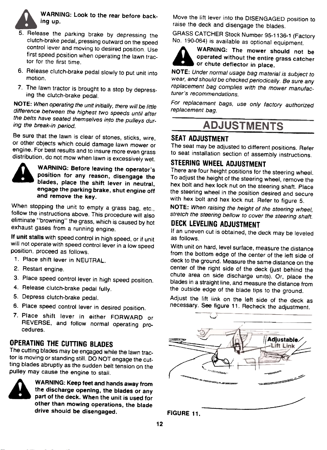
DECK LEVELING ADJUSTMENT
If an uneven cut is obtained, the deck may be leveled
as follows.
With unit on hard, level surface, measure the distance
from the bottom edge of the center of the left side of
deck to the ground. Measure the same distance on the
center of the right side of the deck (just behind the
chute area on side discharge units). Or, place the
blades in a straight line, and measure the distance fromthe
outside edge of the blade tips to the ground.
Adjust the lift link on the left side of the deck asnecessary.
See figure 11. Recheck the adjustment.
OPERATING THE CUTTING BLADES
The cutting blades may be engaged while the fawn tractor is moving or standing still. DO NOT engage the cutting blades abruptly as the sudden belt tension on the
pulley may cause the engine to stall.
WARNING: Keep feet and hands away from
the discharge opening, the blades or any
part of the deck. When the unit is used for
other than mowing operations, the blade
drive should be disengaged.
'-'II~dJU.t.b::::::~:::::~-~
~~-==:~-===="==""~
~/~
FIGURE 11.
12
c~~
-'"-=""
,//
Page 13

SPEED CONTROL ADJUSTMENT (See figure 12)
NOTE: When operating the unit initially or after replac-
ing the belt5. there will be little difference between the
highest two speeds until after the belts have gone
through a break-in period and have seated themselves
into the pull~ys.
First. adjust the speed control lever by pushing the
clutch-brake pedal forwaroj until the stop on the brake
rod is against the frame ..e figure 12. Have another
person hold the pedal in this position as you make the
following adjustment. Place the speed control lever in
parking brake position. Remove the hairpin clip and flat
washer. and adjust the ferrule on the rod so it is against
the back end of the slot. See figure 12. Replace the
flat washer and hairpin clip.
Next. adjust the speed control link as follows to obtain
the correct neutral adjustment.
1. Start the engine.
2. Place the shift lever in Neutral position.
3. Place the speed control lever in high speed
position.
4. Release ~h~ clutch-brake pedal completely, then
slowly depress the pedal all the way (to park posi-
tion). Hold the pedal in this position.
5. Turn the engine off.
6. After engine stops completely, release the clutchbrake pedal.
7. Place speed control lever in first position.
8. Remove the cotter pin and flat washer which
secures the speed control link to the variable speed
torque bracket assembly.
9. Push the clutch-brake pedal backward by hand as
far as it will go using light pressure. Hold it in this
position as you thread the speed control link in or
out of the ferrule until it lines up with the pin on
the variable speed torque bracket assembly.
10. Secure speed control link to variable speed torque
bracket assembly with flat washer and cotter pin.
NEUTRAL ADJUSTMENT
1 Place the transmission in neutral. (The unit will
move freely when pushed forward and backward
with the parking brake released.)
2. Loosen the bolt which secures the shift lever
assembly to the shift lever link. See figure 13.
3. Place the shift lever in the netural slot. See figure
13.
4. Tighten the bolt to 13 foot pounds.
Variable Speed
Torque Bracket
Assembly
",'
.,.,~ -
~
.."""
,~
of Slot
Clip and
Flat Washer
.'.':-. -
i~~- ~.. :;:-
.:r~",- ~ -o i:.:--:-- ~~~"
1 "(~---'- ~~:'-.! ,/ -'~': ,,' ':.;::.. --:-::'. '
,. ,-
/;
"""
.-.,-
~ '~'~ --I '.
-'-- '... -
",
.,., -..~ ;~..
..'.. -
,.' .
~ --.+- ,
"" .~.;.::~ ';,\
Brake
Rod
Speed
Control
Lever
...'-~~~
~
,\
'~
Cotter Pin
and Flat Washer
~-~
~ ,,-",,-~ -'~-::.;:-~~
~- -~+... -
~",,- ,~- 'F".",--
-~:- Speed Control "~"'" "--~_::~ -.~ ~ Rod ""O."--:;""'"' :---~ "-
~Ferrul;"~.~. .-' --,.~(
-~
-'., ~-~ --'~ -.,)
'"'-
J ~
~~
~ --.f;
,- -
---
--'-.
'+..~
",
~ :':"
~
Q~ -~
"", --
-"""""""~
--
,
" -
" r
,; !
...\
' ""
::;;::::--
~
Speed Contro!
/::
)l': ,I "
-::
/
,
Ferrule
'
FIGURE 12.
13
.~~_.~
Page 14

FIGURE 13.
FIGURE 15.
BRAKE ADJUSTMENT (See figure 16)
The brake is located by the right rear whee! inside the
frame. During normal operation of this machine, the
brake is subject to wear and will require periodic
examination and adjustment.
WHEEL ADJUSTMENT
The caster (forward slant of the king pin) and the
camber (tilt of the wheels out at the top) require no ad-
justment. Automotive steering principles have been
used to determine the caster and camber on the trac-
tor. The front wheels should toe-in 1/8 inch.
To adjust the toe-in, follow these steps.
1. Remove the hex nut and lock washer, and drop
the tie rod end from the wheel bracket. See figure
14.
2. Loosen the hex jam nut on tie rod.
3. Adjust the tie rod assembly for correct toe-in.
Tie"
Rod
FIGURE 14.
Dimension "B" should be approximately 1/8" less than
Dimension "A." See figure 15.
A.) To increase Dimension "B," screw tie rod into tie
B.) To decrease Dimension "B," unscrew tie rod from
C.) Reassemble tie rod. Check dimensions. Readjust
Hex,
Nut
Hex Nut
Lock Washer Tie Rod
End
rod end.
tie rod end.
if necessary.
WARNING: Do not have the engine running
when you adjust the brake.To
adjust the brake, remove the cotter pin. Adjust the
castle nut so the brake starts to engage when the brake
lever is V4 II to 5/16" away from the axle housing.
NOTE: Figure 16 is shown with the unit tipped up onrear
wheels for clarity only.
A WARNING: Always stop engine and
disconnect spark plug wire before clean-
ing, lubricating or doing any kind of work
on lawn tractor.
STEERING GEARS
Lubricate teeth of steering gears with automotive multipurpose grease after every 25 hours of operation or
once a season. See figure 17.
14
Page 15

STEERING SHAFT
Lubricate steering shaft at least once a season with light
oil.
ENGINE
Refer to the engine section of Iris manual for all engine
maintenance instructions.
CLEANING ENGINE AND BLADE HOUSING
Any fuel or 011 spilled on the machine should be wiped
off promptly. Grass, leaves, and other dirt must not be
left to accumulate around the cooling fins of the engine
or on any part of the machine
Clean the underside of the blade housing after each
mowing.
CUTTING BLADES
A. Removal for Sharpening or Replacement
-
FIGURE 17.
Steering Gears
VARIABLE SPEED PULLEY
Lubricate needle bearings inside the variable speed
pulley with light oil once a season. Also lubricate the
bearings inside the pulley by putting a small amount
of light oil ort the shaft. Then start the tractor, and with
the shift lever in neutral, move the speed selector forward and backward which will move the center sheave
and distribute the oil on the shaft. Be careful not to get
oil on the sheaves of the pulleys or on the belts. which
could cause the belts to slip.
TRANSAXLE
The transaxle is lubricated at the factory and does not
require che(:king. If disassembled for any reason,
lubricate with 10 oz. of Shell grease, part number
737-0148 (16 oz. package).
The rear axles may be lubricated once a season, us-
ing the access hole on each side of the transaxle housing. See figure 16. A push-type hand grease gun.
equipped with a special flush coupler is required. Use
Shell grease, part number 737-0148 (16 oz. package).
WHEELS
The f, Jnt wheels are provided with grease fittings. The
rear wheels must be removed from the axle for lubrication. Lubricate both front and rear wheels at least once
a season with automotive multi-purpose grease.
PIVOT POINTS
Lubricate all pivot points with light oil at least once a
season.
MAINTENANCE
A WARNING: Disconnect the spark plug wire
and ground against the engine before performing any repairs or maintenance.
TROUBLE SHOOTING
Refer to page 24 of this manual for trouble shooting
information.
A WARNING: Be sure to disconnect and
ground the spark plug wire and remove
ignition key before working on the cutting
blade to prevent accidental engine starting. Protect hands by using heavy gloves
or a rag to grasp the cutting blades.
1. Remove the large bolt and lock washer which holds
the blade and adapter to the blade spindle.
2. Remove the blade and adapter from the spindle.
3. If the blade or blade adapter needs replacing.
remove the two small bolts, lock washers and nuts
which hold the blade to the adapter.
B. Sharpening
Remove the cutting blades by following the directions
of the preceding section.
When sharpening the blades. follow the original angle
of grind as a guide. It is extremely important that each
cutting edge receives an equal amount of grinding to
prevent an unbalanced blade. An unbalanced blade will
cause excessive vibration when rotating at high speeds.
may cause damage to the mower and could break,
causing personal injury.
The blade can be tested for balance by balancing it on
a round shaft screwdriver. Remove metal from the
heavy side until it balances evenly
NOTE: It is recommended that the blade always be
r'emoved from the adapter for the best test of balance.
C. Reassembly
Before reassembling the blade and the blade adapter
to the unit. lubricate the spindle and the inner surface
of the blade adapter with light oil. Lubricating the bolt
holes, bolts and inner surface of the nuts with light oil
is also recommended. A 4 oz. plastic bottle of light oil
lubricant is available. Order part number 737-0170.
Engine oil may also be used.
When replacing blades, be sure to install the blade with
the side of the blade marked "Bottom" (or with part
number) facing the ground when the mower is in the
operating position.
15
Page 16

Blade Mounting Torque
3/8" Dia. Bolt 375 in. Ib, min.. 450 in. Ib, max.
5/16" Dia. Bolt 150 in. Ib, min., 250 in, Ib, max,
To insure safe operation of your unit, ALL nuts and bolts
must be checked periodically for correct tightness.
FUEL FILTER
Your unit is equipped with a replaceable in-line fuel
filter. Replace filter whenever contamination or
discoloration is noticed. Order replacement- filter
through participating Western Auto Stores.
BELT REMOVAL AND REPLACEMENT
WARNING: Disconnect the spark plug wire
and ground it against the engine. Block the
wheels of the unit.
NOTE: Figures 18 and 22 through 24 are shown with
the unit tipped up for clarity. It is not necessary to tip
the unit to remove the belts.
However, if tipping the unit is desired, remove the bat.
tery from the unit. To prevent gasoline leakage, drain
the gasoline, or remove the fuel tank cap, place a thin
piece of plastic over the neck of the fuel tank and screw
on the cap. Be certain to remove the plastic when
finished changing the belts. Block unit securely.
Deck Belt Removal and Replacement
1. Place the lift lever in the disengaged position.
2. Remove the hex bolts (belt keepers) from the
engine pulley belt guard. See figure 18.
NOTE: When reassembling, make certain hex bolts are
assembled in the same locations from which they were
removed. See figure 1 B.
5. Disconnect the spring which is attached to a
bracket on the transaxle. inside the left rear wheel.
Use a spring puller or other suitable tool.
6. Disconnect the six deck links by removing the hairpin clips and flat washers.
7. Disconnect the stabilizer plate from the stabilizer
shaft assembly by removing the hairpin clips and
flat washers and sliding out the rod.
8. Place the lift lever in the disengaged position.
9. Slide the deck from beneath the lawn tractor.
10. Remove the belt guards at each deck pulley by
removing the hex bolts, lock washers and hex nuts.
See figure 19.
Belt Guard
FIGURE 19.
11. Remove and replace the belt, reassemble following the instructions in reverse order.
Rear Drive Belt
1. Place shift lever in neutral position. Unscrew the
shift knob. Remove the two truss head screws
which secure the transmission cover. See figure
20A.
2. Lift the transmission cover. Unplug the safety wire
from beneath the transmission cover. See figure
208. Remove transmission cover.
{/~
3.
Unhook the deck belt from the engine pulley.4.
Place the lift lever in the engaged (all the way forward) position.
rAI/ ,-j IBI [
'7 /;/ .~ I
\\
\\
FIGURE 20.
16
Page 17

3 Push the idler pulley toward the right side of the
unit. Lift the belt over the idler pulley. See figure 21 .
4 Remo\'e the belt from the variable speed pulley.
5. Remo'v.e the two bolts which hold the shift lever
bracket to the frame on the left side of the unit.
Swing ~he bracket toward the right so the belt can
be removed from the transmIssion pulley. See
figure ;~1.
6. Replace belt, and reassemble in reverse order
FIGURE 21.
Front Drive Belt
1. To remol/e the front drive belt. first remove the rear
drive belt from the idler pulley and variable speed
pulley.
2. Place the lift lever in the disengaged position.
3. Remove the three hex bolts (belt keepers) from the
engine pulley belt guard. Refer to figure 18.
NOTE: MakE~ certain hex bolts are reassembled as
shown in figure 18.
4. Unhook the deck belt from the engine pulley.
5. Remove the two bolts. lock washers and nuts on
each side of the frame which hold the engine pulley
belt guard to the frame. See figure 22.
6. Remove the engine pulley belt guard by slipping
it back and to the right. See figure 23.
FIGURE 23.
7. Place the clutch-brake pedal in park position.
8. Push forward on the variable speed pulley I and lift
the belt off the engine and remove the belt from
the engine pulley
9. Release the clutch-brake pedal. Using the pedal
to move the variable speed pulley as necessary,
lift the belt up and off the variable speed pulley.
NOTE: When reassembling, make certain belt is inside
the pins. See figure 24.
FIGURE 22.
FIGURE 24.
10. Reassemble with a new belt. following instructions
in reverse order.
17
Page 18

BATTERY REMOVAL OR INSTALlATION
A WARNING: When removing the battery,
follow this order of disassembly to prevent
the screwdriver from shorting against the
frame.
1. Remove the Negative cable.
2. Remove the Positive cable.
To install a battery:
1. Attach the Positive cable.
2. Attach the Negative cable.
JUMP STARTING
1. Attach the first jumper cable from the Positive terminal of the good battery to the Positive terminal
of the dead battery.
2. Attach the second jumper cable from the Negative
terminal of the good battery to the FRAME OF THE
UNIT WITH THE DEAD BATTERY.
COMMON CAUSES FOR BATTERY FAILURE ARE:
1. Overcharging
2. Undercharging
3. Lack of water
4. Loose holds downs and/or corroded connections
5. Excessiv~ loads
6. Battery :':trolyte substitutes
7. Freezing of electrolyte
NOTE: THESE FAILURES DO NOT CONSTITUTE
WARRANTY.
TIRES
Recommended operating tire pressure is approximately
12 p.s.i. (check sidewall of tire for tire manufacturer's
recommended pressure). Maximum tire pressure under
any circumstances is 30 p.s.i. Equat tire pressure
should be maintained on all tires.
When installing a tire to the rim, be certain rim is clean
and free of rust. Lubricate both the tire and rim
generously. Never inflate to over 30 p.s.i. to seat beads.
A WARNING: Failure to use this starting pro-
cedure could cause sparking, and the gas
in either battery could explode.
BATTERY MAINTENANCE
1. Check periodically (every two weeks or before and
after charging) to be sure electrolyte level is above
the lowest line on battery. Add only distilled water
or a good quality drinking water. NEVER add additional acid or other chemicals to battery after in-
itial activation.
2. The battery should be checked with a hydrometer
after every 25 hours of operation. If the specific
gravity is less than 1.225. remove battery and
recharge.
3. Coat the terminals and exposed wiring with a thin
coat of grease or petroleum jelly for longer service
and protection against electrolyte corrosion,
4. The battery should be kept clean. Any deposits of
acid should be neutralized with soda and water.
Be careful not to get this solution in the cells.
BATTERY STORAGE
1. Charge battery using normal methods. NEVER
store discharged battery as it will not recover.
2. When storing battery for extended periods, disconnect battery cables. Removing battery from unit is
recommended.
3. Store in cold, dry place.
4. Recharge battery whenever the specific gravity is
less than 1.225, before returning to service, or
every two months, whichever occurs first.
A WARNING: Excessive pressure (over 30
p.s.i.) when seating beads may cause
tire/rim assembly to burst with force suffi-
cient to cause serious injury.
STORAGE
If the machine is to be inoperative for a period longer
than 30 days, prepare for storage as follows.
1. Clean the engine and the entire unit thoroughly.
2. Lubricate all lubrication points. Wipe the entire
machine with an oiled rag to protect the surfaces.
3. Refer to the engine section of this manual for correct engine storage instructions. The engine must
be completely drained of fuel to prevent gum
deposits from forming on essential carburetor
parts, fuel lines and fuel tanks.
4. Refer to battery storage instructions on this page.
5. Store unit in a clean, dry area.
NOTE: When storing any type of power equipment in
an unventilated or metal storage shed, care should be
taken to rustproof the equipment. Using a light oil or
silicone, coat the equipment, especially any chains,
springs, bearings and cables.
OFF-SEASON
18
Page 19

FOR ENGINE MODEL 281707-0411-01
IMPORT ANT: Do not start the engine before reading
the following section of this manual.
A WARNING: Do not operate engine in an
enclosed area. Exhaust gases contain carbon monoxide, an odorless and deadly
poison.
AI'Nays remove ignition key and disconnect
spark plug wire from spark plug before performing any repairs or maintenance.
SECTION "1
BEFORE STARTING
Fill Sump With Oil-Use a high quality detergent oil
classified "~or Service SF, SE. SD or SC." Nothing
should be added to the recommended oil.
Place engirle level. Clean area around oil fill before
removing oil dipstick.
Remove oil dipstick. Fill to full mark on dipstick. Pnur
slowly. Capacity approximately 3 pints; however, a
small amou'1t of oil may be present from the factory.
When checking oil level, screw dipstick assembly firmly
but slowly until cap bottoms on tube. Do not overfill
or excessive smoking may occur when engine is run-
ning. Dipstick assembly must be securely assembled
to tube at all times when engine is operating.
NOTE: Be ,:ertain to fill only to the full mark on the
dipstick. Do not overfill.
Fill Fuel Tank-The engine will operate satisiactorily
on any gasoline intended for automotive use. DO NOT
MIX OIL WITH GASOLINE.
The use of clean, fresh, lead.free gasoline IS recom-
mended. Leaded gasoline may be used if lead-free is
not available. A minimum of 77 octane i.c reCOrTtmended. The use of lead-free gasoline results in fewer
combustion deposits and longer valve life.
Do not fill fuel tank to point of overflowing. Allow tank
space for fuel expansion
Recommended SAE Viscosity Grades
19
Page 20

SECTION 2
STARTING
A WARNING: ALWAYS KEEP HANDS AND
FEET CLEAR OF MOWER BLADE OR
OTHER ROTATING PARTS.
~ "'\
'. ~~ \~ -.,'~~:-
~", -, --
,~- .~':(~::~l~~~'~~':
))
Lift
To Start Engine
1. Depress the clutch-brake pedal and set the parking brake.
2. Place the lift lever in the DISENGAGED position.
3. Set the throttle control in the FAST position.
4. Pull choke knob out to choke engine.
NOTE: A warm engine requires less choking than a
cold engine.
5. Turn the ignition key to the START position. When
the engine is running, let the key return to the ON
position.
NOTE: The best starter life is provided by using short
starting cycles of several seconds. Prolonged cranking can damage the starter motor if cranked more than
15 seconds per minute.
6. Push choke knob in gradually. Move the throttle
control to desired engine speed.
To Stop Engine-Turn ignition key to OFF position.
CAUTION: Always remove key from switch when leav-
ing equipment unattended or when equipment is not
in use.
SECTION 3
REGULAR MAINTENANCE
A WARNING: TO PREVENT ACCIDENTAL
STARTING when performing any /' .
maintenance or repairs, always disconnect
spark plug wire from spark plug and ground
against the engine.
SURE PROPER OIL LEVEL IS MAINTAINED.
Change Oil after first five hours of operation. Thereafter
change engine oil every 50 hours, under normal
operating conditions. Change engine oil every 25 hours
of operation if the engine is operated under heavy load,
or in high ambient temperatures. Change oil while
engine is warm. Oil may be drained through oil drain
plug on side of engine.
Air Cleaner
Service air cleaner at three month intervals or every
25 hours, whichever occurs first.
NOTE: Service air cleaner more often under dusty con-
ditions.
To Service Air Cleaner:
1. Remove two cover knobs and remove air cleaner
cover.
-'--
Throttle
Clutch-
Brake
Pedal'
/"
Cold Weather Starting Tips
1. Be sure to use the proper oil for the temperature
expected.
2. Declutch all possible external loads.
3. Set throttle control at part-throttle position.
4. A slightly richer fuel mixture, obtained by turning
carburetor needle valve 1/8 turn counterclockwise,
will usually improve cold starting.
5. A warm battery has much more starting capacity
than a cold battery.
6. Use fresh winter grade fuel. (Winter grade gasoline
has higher volatility to improve starting. Do not use
gasoline left over from summer.)
I\UJ
~"
'-1
\Check Oil Level after each five hours of operation. BE
Q:9 "-'
Oil Drain Plug
~
11"'0
I
-.d-- Cover~
.~~ Knobs "'~#' .
To Remove
, Cover
~
~/ ../ Cartridge
~ Nuts
.Fiber
~~:~~ Washer
-~ .Foam
'r::::;--- Pre-Cleaner
Air Cleaner
Base
~~
J'
20
Page 21

2 Remove foam pre-cleaner. Spark Plug-Clean and reset gap at .030" every 1 00
a. Wash pre-cleaner in liquid detergent and warm hours of operation.
water to remove dirt. NOTE: Do not blast clean spark plug. Spack plug
b. WrElp pre-cleaner in cloth and squeeze dry. should be cleaned by scraping or wire brushing and
c. Saturate foam in engine 011. Squeeze to
remove excess oil. Caution: Sparking can occur if wire terminal does not
3. Remove two nuts rom top 0 cartrl ge.
4. Remove cartridge and clean air cleaner body is equipped with spark arrester screen assembly,
carefully to prevent dirt from entering carburetor. remove every 50 hours for cleaning and inspection.
Brush ,jirt from lower air cleaner body Into duct. Replace if damaged.
5. Clean cartridge by tapping ~ently on flat ~urface Fuel Filter-Replace in-line fuel filter every season.
a. If very dirty, replace cartridge or wash In a low
or non-sudsing detergent and warm water
solution.
b. Rinse thoroughly from inside out until water is
clear.
c. Cartridge must be allowed to stand and air ry
thoroughly before using.
6. Reassemble air cleaner. f
Caution: Petroleum solvents, such as kerosene, are
not to be used to clean cartridge. They may cause
deterioration of the cartridge. Do not oil cartridge. Do
not use pressurized air to clean or dry cartridge. (
f f .d fit firmly on spark plug. Reform terminal if necessary.
.Spark Arrester Equipped Muffler-If engine muffler
.washing with a commercial solvent.
~ \
I IIn-Line
.
d I
Filter
~~~::::~~~ ~
; :-- -,~
1/_-
Clean Engine-Remove dirt and debris with a cloth or
\brush. Clea,1ing with a forceful spray of water is not
recommended as water could contaminate the fuel I
system.
Clean Cooling System-Grass. chaff or dirt may clog ---~-
the rotating s,creen and the air cooling system, especial- Remove Combustion Deposits every 100-300 hours
Iy after prolonged service in cutting tall dry grasses. of operation. Remove cylinder head and cylinder head
Yearly or e'/ery 100 hours, whichever occurs first, shield. Scrape ar,d wire brush the combustion deposits
remove the blower housing and clean the areas shown from cylinder, cylinder head, top of piston and around
to avoid ol/erspeeding, overheating and engine valves. Use a soft brush to remove deposits. Re-
damage. Clean more often if necessary. assemble gasket, cylinder head and cylinder head
WARNING: Periodically clean muffler area to shield. Torque cylinder head screws in a staggered seremove all grass, dirt and combustible debris. quence to 140 inch pounds (15.82 Nm).
SECTION 4
~ADJUSTMENTS.
CARBURETOR ADJUSTMENT
A WARNING: If any adjustments are made to
the engine while the engine is running
(e.g. carburetor), disengage clutches and
bla,des. Keep clear of all moving parts. Be
careful of heated surfaces and muffler.
Minor carburetor adjustment may be required to com-
pensate for differences in fuel. temperature, altitude or
load.
NOTE: The air cleaner must be assembled to carburetor wherl running engine.
To Adjust C;~rburetor-Gently turn valves clockwise
Mixture r ~
i I / =.. \ \ \.
Idle Speed I
Adjusting
Screw I
Throttle
Stop
until they just close. Valves may be damaged by turn-
ing them -roo far.
-
."
Throttle
\..I.J (High Speed)
Out Chaff
and Dirt
y
-'
Needle Valve
:;.?
~
~
Idle
Ijo~
21
Page 22

Now open needle valve 1-1/2 turns counterclockwise
and idle valve one turn. This initial adjustment will per-
mit the engine to be started and warmed up approx-
imately 5 minutes prior to final adjustment.
Final Adjustment-Place speed control lever in FAST
position. Turn needle valve in until engine slows (clockwise-lean mixture). Then turn it out past smooth
operating point (rich mixture). Now turn needle valve
to midpoint between rich and lean. Next, adjust idle
RPM. Rotate throttle counterclockwise and hold against
stop while adjusting idle speed adjusting screw to ob-
tain 1750 RPM. Holding throttle against idle stop, turn
idle valve in (lean) and out (rich). Set at midpoint between rich and lean. Recheck idle RPM. Release throttle. If engine w111 not accelerate properly, the carburetor
should be re-adjusted, usually to a slightly richer
mixture.
CONTROL ADJUSTMENTS
Proper choke and speed control operation is dependent upon proper adjustment of controls on the powered
equipment.
To Check Operation
Move control lever to CHOKE position. The carburetor
choke should be closed.
To Adjust Choke:
Place control lever on equipment in CHOKE position.
Loosen casing clamp screw. Move casing and wire until
choke is completely closed. Tighten casing clampscrew.
- ~~~:;qll~~~
~- ~ ~
J
~ °!8-C~'ok~ .
Casing
Clamp
Screw
Fast Position
~' E
I '
\~' ,,\
F
Throttle Control Adjustment
Place speed control lever on equipment in FAST (high
speed) position. Loosen casing clamp screw "C," Move
casing "A" and wire until lever "E" touches link at "F,"
Tighten casing clamp screw "C." Move control to
STOP position. Lever must make good contact with
stop switch.
SECTION 5
GENERAL INFORMATION
ENGINE DESIGN
This engine is single cylinder L-head. air-cooled type.
MODEL SERIES 281707
Bore 3-7/16"(87.31 mm)
Stroke 3-1/16" (77.78mm)
Displacement. 28.42 cu. in. (465.7 cc)
Horsepower Max. '."'..' ' .12 @ 3600 APM
Torque (Ft.-Lbs.) Max. 20.5 @ 2400 APM
The horsepower ratings listed are established in
accordance with the Society of Automotive Engineers
Test Code-J607. For practical operation, the
horsepower loading should not exceed 85% of these
ratings. Engine power will decrease 31/2% for each
1,000 feet above sea level and 1 % for each 100 above
600 F.
In some areas, local law requires the use of a resistor
spark plug so as to suppress ignition signals. If an
engine was originally equipped with a resistor spark
plug, be sure to use the same type of spark plug for
replacement.
Major engine repairs should not be attempted unless
you have the proper tools and a thorough knowledge
of internal combustion engines.
TUNE-UP SPECIFICATIONS
Spark Plug Type Champion Autolite
~. Short Plug CJ-8 235
Long Plug J-8 295
Resistor Short Plug RCJ-8 245
Resistor Long Plug RJ-8 306
Spark Plug Gap 030"
Intake Valve Clearance. 005"-.007"
Exhaust Valve Clearance. 009"-.011"
22
"---T~
Page 23

STORAGE INSTRUCTIONS
Engines to be stored over 30 days should be completely
drained of fuel to prevent gum deposits forming on
essential carburetor parts, fuel filter and tank.
NOTE: The use of a fuel additive. such as STABIL, or
an equivalent. will mil'limize the formation of fuel gum
deposits during storage. Such an additive may be
added to the gasoline in the fuel tank of the engine.
or to the gasoline in a storage container8.
All fuel should be removed from the tank. Run the
engine until it stops from lack of fuel.
b. While engine is s1ill warm, drain oil from crankcase
Refill with fresh oil,
c. Remove spark plug, pour approximately '/2 ounce
(15 cc) of engine oil into cylinder and crank slowly
to distribute oil. Replace spark plug.
d. Clean dirt and chaff from cylinder, cylinder head
fins, blower housing, static guard and muffler areas.
e. Store in a clean, dry area.f.
Charge battery and store as recommended on page
18.
23
Page 24

TROUBLE SHOOTING CHART FOR ELECTRIC START MODELS
TROUBLE
Engine will not
crank
LOOK FOR
Battery installed Incor.
rectly
Blown fuse or CirCUli
breaker
Battery is dead or weak
-REMEDY- ---:J
The battery must be instatled with the negative terminal, identified at t'le terminal post by (Neg. N
or -). grounded The positive terminal (Pos, P or ..) attaches to the large cable from the solenOid
The small red wire from the fuse holder or cirCUit breaker IS also attached to the positive termInal
Replace fuse with 7'/2 amp fuse 'I. x 1 '1." Ig CircUit breaker WIll reset Itself when it cools off Fuses
or circuit breakers seldom open or fail without a reason The problem must be corrected Check for
loose connections In the fuse holder Replace fuse holder if necessary A dead shon may be In the
cranking or charging Circuit where the Insulation may have rubbed through and exposed the bare
wire Replace the wIre or repair with electrician's tape if the wire strancs have not been damaged
Note: Look for a wire pinched between body panels. burned by the exhaust pipe or muffler or rubbed
Use a hydrometer to check the condition of 1he battery The SpecIfic GravIty (sg) should be 1 265
at 80°F (1.215 sg minimum needed for cranking engine) 'he reason for the batter,. failing must
be determined (1) Defective battery Battery will not accept or hold a full charge (2) Short circuIt.
Check for grounded wire (3) Charging system not working
The charging system IS an alternator located under the flywheel It IS unregulated and rated 3 amp
at 3600 r.pm A diode (rectifier) IS located In the output lead just befort! the wIre harness plug on
the engine side
Red
Wire
To Alternator <) ~ ~ ~
Diode
--.'
--~
t,:.;';';;;;"D._~
I--'
s
Black
Wire
Polarized
Plug
Iagainst a movIng pan
The diode changes AC to DC to charge the battery A bad diode can either fall to charge the bat.
tery or discharge the battery If the alternator IS shorted as well as the diode To test: (1) Disconnect
charger lead from the battery (small red wire) (2) Connect 12 V small test lamp between the 3 amp
DC charge lead and the positive terminal of the battery. (3) With the engine off, the lamp should
not lIght If It does. the diode and possibly the alternator should be replaced (4) Stan the engine
The lamp should light. If it does not, the alternator (stator) or lead wIre IS bad and should be replaced
Mechanical failure
(Wires and swItches)
Engine cranks
but will nol star1
., I Replace il it does not J
Throttle or choke not in
starting poSition
No spark to spark plug Spark plug lead disconnected Connect lead Hold spark plug lead away from engine block about
The interlock system Includes two mechanical activated switches which are wired in series in the
circuit used to energize the starter solenoid While testing the InterlocK system, you will make the
mower temporarily unsafe by permit1ing the engine to be started wIth the blade and clutch engaged
WARNING While testing, disengage the clutch, shut off the blade control, set the parking brake and
place the gear shift lever in neutral. Attach a wire (minimum 18 gauge) to the positive terminal of the
battery and touch the other end to the small terminal on the solenoid If the engine does not crank: (1)
There is a loose connection or poor ground (2) The solenoid may be bad The solenoid can be checked
by using a heavy wire (*8 gauge minimum) and Jumping between the two large terminals If the engine
cranks, the solenoid is bad. (3) If the engine does not crank when you jump the solenoid, have the
starter motor tested by an authorized engine dealer If the engine does crank. the problem is with
one of the safety switches. Ignition switch or the wire between the fuse holder (or circuit breaker) and
the small terminal on the solenoid. Note: Look for a poor connection at the switches or a defective
swItch Replace if necessary
Check owner's guide for correct position for throttle control and choke for starting
1/8" Crank engine. There should be a spark II not. have engine repaired at local Western Auto Ser-
vice Center.
Faulty spark plug To test. remove spark plug. Attach spark plug lead to sparl\ plug. Ground the spark
plug body against the engine block. Crank the engine. The spark plug should fire at the electrode.
24
Page 25

ILLUSTRATED PARTS FOR MODEL
MT[)7122BO9 LAWN TRACTOR
PARTS LIST FOR MODEL MTD7122BO9 LAWN TRACTOR
~~j NO.
1
710-0924
2
1 16195 3 720-0218
4 16192
5 ' 736-0192
6 711-0198
7 738-0155
I ~! ~~~~~~~~J~
I 9 i 714-0507
Truss Mach. Scr. '/4-20 x j
.75" Lg. i
5-Speed Selector Plate !
Shift Knob
Speed Selector Cam Ass'y.
Flat Washer .53" 1.0. x .93"
Ferrule 3/8-24 x .37" Dia.
Shoulder Bolt
Speed Control Link
Cotter Pin 3/32" Dia. x .75".
DESCRIPTION
,
I REF.-+-~PART
NO.
10 736-0226
11 736-0119
12 712-0267
13 714-0507
14 732-0303
17 736-0140
18 726-0235
19 736-0329
20 1712-0287
""-
l-Wash. 5/16" I.D.*
Hex Nut 5/16-18 Thd.*
Cotter Pin 3/32" Dia. x .75" *
Spring .38" C.D. x 3.18" Lg.
FI-Wash. .385" I.D. x .62"
Speed ClipL-Wash.
Hex Nut 1/4-20 Thd.*
DESCRIPTION
.469" I.D. x .88"
1/4" 1.0. *
~T-Pm-
FI-Wash.
25
Page 26

~
~~8
~
'"
21. '.
41
17
~
11-;-\((
15-i \ \
~'
1.Q .
5 ..
6
1.2./
.
..r
L;,
1
"
I.
6
\ ~'5
w/
17
3
~
"
6$
,
36,~
'~'..~' -~'- ~.. .
~~:;~ .,'
-.~
~\.~.
35
21
31
z: .
r'--
":)
,~
~
/1"~\
I
10
Page 27

Il.LUSTRATED PARTS FOR MODEL
MTD7122BO9 LAWN TRACTOR
""':~
""""
~ ~ ~ 1
---QI 55 '
:.-~-:-~ ~ 58,' ,'26 t
~;;--o:;;;~~~>... ',.f ! I 51
~
~<...y 16 a.1.8
~
-.', ~ rZ ~ I
i
6
To Battery ~
.-""",- 32 ! \'.. ,. ,~~\\ ~..,~""',.,~- i 51' .~ ,~- 52
5'
:5 m '
i
2 z .
;;
,26":
33
/
I :'
--I
-;..;,.;.
60~ oiI.,~ ~ .,.~-"'-;:;:~'c-. !' ,.~.. .:--.
51~ ...~""= .
-'---~i=~ ,~."" ..2fI ~p:'833 C~-
~~y--- 52" ' fl
IJ-.'\:':-:~:'::'--:- ---:--- 117 ~I_/...~~
'4--:: <~;~-"--:-'-'
-'-, A ~ ---'~ c --2
!~~ '.' .A~ 51-- / '---c-., -~~~
T
33 U-~~~~~ 29 --, ~2 59 13/ 30 57
17
N--,"'" ~ =?~;;~- II ~
7-- 61
~-'y--w
"'~i
~
44
/
I
1-'3
'5
~"':~~. ;--8
-..r ~ 9
j ,
~-
or
SP
I
/
~~""'zz-4:- -"';
""-'
~
1.6, t .~
,...~~~::~
~- "II 3' '47
~:~:~~~:-::~- 21.
: ,!
..?""" --.
/1" -., -,-,;' w
~
"
.-:::::--
61
4
4,15 I
£.-:\ I ~
1. .y
t :.~--
-~.-;;;./..
29
NO. NO.
I 1 736-0159-'
I 2 1710-0817
I 3 738-0155
i 4 738-0145
I 5 736-0141
I 6,156070
I 7 i 723-3071
I 8 i 751-0553
I 9 i 726-0209
10 .751-0535-15
11 726-0205
13 712-0287
14 736-0329
16 732-0588
171 723-0360
21 738-0526
22 1710-0227
23 726-0139
24 17621
25 710-0623
26 I 710-0726
1 28 1 710-0134
29 17770
30 1 761-0168
133 710-0323
-. t1EF. PART
PARTS LIST FOR MODEL MTD7122BO9 LAWN TRACTOR
I DESC~IPTIO~ 'REF.
\ FI-Wash. .344" 1.0. x .875"
Hex Wash. Hd. Tap Scr.
\ 5/16-18 x 1.25" Lg.
Shld. Bolt .437" Dia. x .162"
Shld. Bolt .50" Dia. x .84"
I Spr-Wash. .445" 1.0. x .75
I Seat Pivot Bracket
\ Fuel Cap w/o Gasket
Fuel Tank
Tie Strap
Fuel Line
I Hose Clamp
Hex Nut '/4-20 Thd.-
\ L-Wash. V4" 1.0.
Compression Spring
t-
! 34 17620 Lower Frame
1 35 736-0169 I L-Wash. 3/8" 1.0.*
I 38 710-0118 Hex Bolt 5/16-18 x .75" Lg.*
! 39 17622 Upper Frame-A.H. ,
I 41 712-0798 Hex Nut 3/8-16 Thd.' i
1 42 732-0581 Extension Spring 5.31 " Lg. I
Foot Pad-.
IRunning Board Rod
Hex Wash. Hd. AB-Tap Scr.
#8 x .50" Lg.
I Speed Nut #10Z
I Front Pivot Brkt
Hex Tap Scr. 3/8-16 x .75"
I Hex Wash. Hd. AB-Tap Scr.
\ 5/16 x .75" Lg.
II Carriage Bolt '/4-20 x .62" .
Running Board (R.H. & L.H.)
, Blade Brake Ass'y.
I ;:;~ss Mach. Scr. 5/16-18 x
J .75" Lg.-
-
: 54 757-0345 Seat
I 55 17702 Seat Pivot Brkt. Support-A.H.
I 56 738-0296 Shld. Bolt .437" Dia. x .268" I
i 57 725-1303 Spring Switch I
I 58 722-0160 Bushing i
I. 59 710-0971 , Truss Hd. Scr. 5/16-18 x 1.0" Lg. .
I
' 60 736-0607 i External L-Wash. 5/16" 1.0.
I ~726-0222 Insulator Nut Plate
I 63 725-1439 Safety Switch (Seat)
: I
I
27
: iT -I. "'.'0' c:.,,~~CRIPTION- --!RT I DESCRIPTION J I DESCR NO. NO.
36 726-0278 i Insulator Center Plate
43 731-0871 A Battery Box w/Cover
44 725-0514A 12- V Battery
45 17623 Upper Frame-L.H.
46 17286 Shift Cover
47 725-0759 Reverse Safety Switch ;
48 726-0279 Insulator End Plate
50 17225A Hitch Plate
52 736-0119 L-Wash. 5/16" 1.0. *
53 17239A Seat Lift Brkt.
61 723-3003
I! 49 17701 Seat Pivot Brkt. Support-L.H.
I1 51 712-0267 Hex Nut 5/16-18 Thd.*
I Fuel Cap Gasket
~t
"
,10
.;-.
~
~
Page 28

Page 29

rAEFT- PART---
~-:-i !!:.O-.:.-- ---
: 1 i 731-0220
2 \ 712-0237
3 736-0242
I 4 i 731-0805
I 51731-0954
, 6'16512
I 71741-0356
I 8 1712-0324
9117198
I 10 1738-0141
11 ;710-0152
1516
-4
Seat
IREF1
[NO-.:J
1 I 725-0514A
2 ,725-1426
3 ' 725-0459
4 725-0634
5 725-,0925
6 725-0267
7 \ 725-3169 8 725.1351
9 725-1494
---r
BI.C~" ~~
~ 10 (q; I
e'
-:::- 8!
:: -1 I
e 8'~-~
I i
~Red~1
PART!
NO. I---
,
Yellow
i
i
!
PARTS LIST FOR ELECTRICAL SYSTEM
DESCRIPTION
--~
Battery
Solenoid
Circuit Breaker
Light Switch
Ammeter
Ignition Switch
Safety Switch (Clutch)
Electric Wire-B" Lg.
Wire Harness
--
--IREF'" I PART -
--
--
---
:..-:-
ClutC~VeIIOW-
-.-Red--o.:c:---
Alt.-,' ,@. 1
-'DIfTi ,.JJ;t::+-- Mag ~ .,:-,
6 --Jf:J /~~.II~~-:?:==~~ '-LI ,
Gm -' 8 ~~. J
4- ~" ... " "
s-[[!iT
Yellow---
-0_-- .
I N~ NO.
10 T 725-0977
: 11 1725-08038
! 12 I 725-0759
i 13 725-1058A
14 725-0963
I 15 725- 1 303
i 16 725-1439
; 17 725-0980
-
S r='"-- tart: -==-..,
:
.-; aU ~ \;:' c
,!: ! II .1
~i! i i!!
.I ! -Red-
~Whlte
iT
-:t=- ==-
'- .,
:'--Green Blue 0
Ground Wire 11.5" Lg.
Safety Switch (Deck)
Safety Switch (Reverse)
Socket
Bulb
Safety-Switch (Seat)
Safety Switch (Seat)
Ground Wire 7.5" Lg.
I -.~-~ ~
13~T
14
~,~fO
~
Page 30

ILLUSTRATED PARTS FOR MODEL
MTD7122BO9 LAWN TRACTOR
1 ~"--'.~: 97
i 'I;' '389.: '85"'~;!J~-
18 B8 ~__~~b~/"A
~ -~
< : ..oJ ~
~ , ~_-\" c'
-~ "'- ., -"""~ rr -~~ .::
!of , ...j' '1
91 .
\
29 ,E;I ~. 8-
~
114
, 86
~5- ' " I
18/ .
IMPORTANT: Use only Original
Equipment Manufacturer (O.E.M.)
V-belts when replacing belts.
They are of special construction
(type of cord, cord location,
length, etc.). Use of V-belts other
than O.E.M. belts generally will
provide only temporary service.
For best results, use only factory
approved parts.
~~'"
II/~
! fr'~
~~\\ .,\~ )
:
..\ .
\\. ~' "'- ,I
~ '
I ,\ , ' ~:-. .\
I
5~ "
58
\
57
Description
Wheel Ass'y. Compo
Tire Only
Rim Only
.! 46-'~
' ' -J ~:;..
-'-'=
~
---80
,-
75
76'
-"'" ',t, 10-A
' 72~~
74
,
: """""' ~~~f
: .,-~
:r- ~
,~-, ..,
I :
,< "_of".
~IL!. , IJI' 'Y.9 i 1/-
I
"~~ I 29 I I 27
2~' , I ~ '
10 '. 1 "" ~~679' 11-~~~~-
32~~ ~
33.,
6'- ~ 31./
39 : ---
" ..
6°, ~~
~~~'-
~~ .,/,,1
ss
56
* *REAR WHEEL CHART
, ---1"
!;
iS2 .-h",'
18" x 6.50"1
734-0592
734-0294
734-0594
y~ /"'=~~ .
¥l--I .0
9 3-~ -:..::..'.
9 C ~~)-
~~. ,/77 .
,_I;' ,-"",.~
7-$ "'., 18:on.tt , 1\
1 .:~t::~~=- .
~! 28 (
--/ ~ ~ -~- -"-'-'6
1,' 8-' '-
-F , /':--
18
~
--63~9
,,-
51
'35--"3
A
'7
t
'O7~
~
101 '
, po,~ '.
18,
Note: If brand of tire is impor-
tant, order by part number and
description (description is
printed on the sidewall of tire)
{i.e. Armstrong Super Turf,
Goodyear Softrac, Carlisle
Turf Saver, etc.].
I
: / ,/
3<
( --17
--'8
~-
~1~'
-~---~2J
2~
: ~~1'
I
/ "S I,DB
A.
\
26
\
"
109
.J7
~, -fV>--
11
'8" """'; \
~
-
~
/8
20~:g
...~---"
'"
./1
~
5'
'~~
'5
~
30
Page 31

I RE"FT-pART~~_t:l~-
1
1 12 H.P.
2,710-0726
I
31725-0977
4
\ 712-0123
5 736-0119
7i 736-0247
9
! 750-0777
10 710-1077
1111 7620
12 1 726-0235 13 712-0287
14 736-0329
15 710-1012
16 15898
17 736-0242
18 712-0267
I 19 710-0190
20 714-0114
I 21 756-0488
I 22 736-0322
, 23 736-0171
24 710-0757
25 754-0280
26 710-0118
27 16553
I
281741-0295
,
29 712-0241
30 17643
31 736-0169
32 712-0241
33 1 7.629
34 732-0556
35 714-01498
361750-0802
37
1 714-0507 39 712-0138
43 710-0599
44'
1 17715 45 736-0117
46 710-0351
I 47 17686
48 735-0196
51 17705
52 710-0559
53 732-0264
54 732-0413
55 710-3056
56 **
57 *.
58
1 734-0255
59 710-0627
, ~I :!:-0542
~~~0454
PARTS LIST FOR MODEL MTD7122BO9 LAWN TRACTOR
c--- ~-r ' , Engine (See Breakdown)! 621 711-0768
~ , DESCRIPTION I REF" PART !
NO. NO. ,
, Hex Wash, AB-Tap Scr, 5/16" x I 63i 736-0275 .I
: 75" 64[710-0428:
: Electric Ground Wire 65
\ 732-0568 '
I L-Wash. 5/16"" I.D.' " I 671 16554A I
FI-Wash, ,406 I.D. x 1.25 ~ I
spacer
Hex L-Wash Tap Scr. 3/8-16 x 69
r 68741-0419 I
1 714-0507
1,5" Lg. 70 748-0234
Lower Frame Ass'y. I 71\ 747-0530
Speed Clip i 721741-0405
Hex Nut V4-20 Thd. * i
I L-Wash, 1/4" I.D.*
I Rib Neck Bolt 5/16-24 x .84" Lg.1
I Belt Guard Brkt. Ass'y. !
I Bell-Wash. .345" 1.0. x .88" j
Hex Nut 5/16-18 Thd,*
Sq. ,Key 1/4" x '/4" X 2,00"
FI-Wash. 7/16" 1.0. x 1.25" ,
L-Wash. 7/16" I.D.* I
731 720-0232
741756-0437
751 756-0563
76: 736-0921
771712-0922
IHex Bolt 5/16-18 x 4,0'"
781 710-0539
79 1 754-0370
80 716-0114
IEngine Pulley
811736-0355
821717-0800
Hex Bolt 7/16-20 x 1.50" Lg,
Variable-Speed Belt
Hex Bolt 5/16-18 x .75" Lg,
Bearing Shaft Bracket
Ass'y.
I Flanged Nyliner Brg. 5/8"
1.0. x .88" Lg.
'
I Hex Nut 3/8-24 Thd. *
Idler Bracket
Hex Nut 3/8-24 Thd.' I
Transaxl.e Sup~,ort Brkt. " I
Ext. Spring .94 0.0. x 7.58
Inter. Cott-Pin
Spacer .63" 1.0. I
Cotter Pin 3/32" Oia. x .75" * i
Hex Nut 1/4-28 Thd.
Hex Wash. Hd, S- Tap Scr. I
'/4-20 x .50" Lg. I
Clutch/Brake Pedal Ass'y.
841163546
851 732-0525
86117668
117669
881 725-1426
89 17630
90
1 736-0414:
,I L-Wash. 3/8" I.D.'
91 725-0459
93 725-3169
94 738-0755
I'
96 748-0334
I 97 736-0105
98 738-0569
99 736-0331
100 736-02561101
714-0111
102 710-0604
105 16067
IFI-Wash.
1106 710-0323
Truss Mach. Scr. B-Tap Scr.
I#10 x .5" Lg.
Brake Rod Ass'y.
Foot Pad
Shift Lever Ass'y.
'10715835A.108
714-0507
\ 109 711-0198
110 710-03761111
Hex Bolt '/4-28 x 1.75" Lg.*
Ext. Spring .38" 0.0. x 2.5"
I Ext. Spring .59" O.D. x 7.08"
Hex Bolt 5/16-18 x 31/4 " Lg.
Wheel Ass'y. Camp.
Wheel Rim Only
Air Valve (Service Only) I
Hex Bolt 5/16-24 x ,75" Lg.* :
Transaxle Complete I
710-01951
112 736-0270
113 17707
114 751-0302!
-712-0250
115 736-01401116
741-0404
118 736-0607
Brake Return Spring Anchor I
DESCRIPTION
Belt Guard Pin 1/4-20 Thd.
FI-Wash- .34" 1.0. x .68" 0.0.
Hex Bolt 1/4-28 x 1.25" Lg..
Ext. Spring
II Hex Nut 5/16-24 Thd.* , 66 732-0384
Ext. Spring .62" 0.0- x 6.12"
Variable Speed Torque
Brkt. Ass'y.
, Flanged Bearing
I Cotter Pin 3/32" Dia..
! Shoulder Spacer .27" Lg.
I Speed Control Link
Truss Bearing .56 Dia. x
1.25"
i Shift Knob
FI-ldler Pulley 3.25" x .75"
, 1/2" "V"-Pulley
L-Wash. 1/2" 1.0.*
Hex Jam Nut 1/2-20 Thd .
i Hex Bolt 3/8-24 x 1.75" Lg.
i Variable Speed Belt
Ii Snap Ring .56" Dia.
FI-Wash.
I Variable Speed Pulley
! Ass'y. 5" 0.0.
I Variable Speed Brkt. Ass'y.
Compo SprIng-Clip
I Axle Support Brkt.-R.H
Axle Support Brkt.-L.H.
! (Not Shown)
I Solenoid
, Shift Lever Bracket
Teflon Washer .565" I.D.
Circuit Breaker
Safety Switch (Clutch)
Shld. Bolt 3/8-24 x 3.12" Lg.
Transaxle Spacer
Bell-Wash. .38" t.D. x .88"
Shaft .56" Dia. x 3.875" Lg.
Bell-Wash. .39" 1.0. x 1.12"
FI-Wash. .64" 1.0. x .94"
Cotter Pin 3/32" Dia. x 1.0" *
Hex Tap Scr. 5/16-18 x .62"
Belt Guard
Truss Mach. Scr. 5/16-18 x
.75" Lg..
Pedal Bracket
Cotter Pin 3/32" Dia. x .7': .
Ferrule
Hex Bolt 5/16-18 x 1.0" Lg.-
(Gr. 5)
Hex Bolt 1/4-28 x .50" Lg.
Bell-Wash. .265" 1.0. x .75"
Shift Lever Link Ass'y.
Muffler
Conduit L-Nut (Not Shown)
FI-Wash. .385" 1.0. x .62"
Needle Brgs. (2 Req'd.)
I External L-Wash. 5/16" 1.0.
I ; i
31
Page 32

REF I
NO.'r
10 712-0267
11 736-0192
12 714-0144
13 736-0256
14 732-0412A
15
16
17
18
19
20
21
22
23
PART
NO.
1 I 09735A
2 17640
3 17641
4 17710
5 14800
6 14804
7 748-0331
8 736-0231
9 736-0119
08540
710-0604
748-0176
710-0650
710-0118
17730
17622
714-0101
736-0267
1--""'"
PARTS LIST FOR MODEL MTD7122BO9 LAWN TRACTOR
DESCRIPTION
Connecting Aod
Pivot Link Ass'y.-L.H.
Pivot Link Ass'y.-A.H.
Deck Hanger Link Ass'y.
Deck Hanger Link Ass'y.
Deck Hanger Link Ass'y.Shld.
Spacer .318" 1.0.
FI-Wash. .344" 1.0. x 1.125"
L-Wash. 5/16" 1.0.*
Hex Nut 5/16-18 Thd.*
FI-Wash. .531" 1.0. x .94" 0.0.
Cotter Pin 1/8" Dia.
FI-Wash. .635" 1.0. x 1.0" 0.0.
Deck Lift-Down Stop (Incl.
Ref. 15)
Knob
Hex Wash. TT -Tap Scr.
5/16-18 x .75" Lg.
Flange Brg. .63" 1.0.
Hex Wash. TT-Tap Scr. 5/16-18
x .875" Lg.
Hex Bolt 5/16-18 x .75" Lg.
Index Brkt.
Upper Frame-A.H.
Inter. Cotter Pin 1/2" Dia.
FI-Wash. .385" I.D. x .87" 0.0.
REF.
133 17637
PART
INO.
NO.
24 736-0160
25 726-0272
26 738-0526
27 710-0351
28 14802A
29 711-0723A
30 17712
31 712-3029
32 711-0841
34 725-08038
35 714-0145
]6 732-0637
37,17636
38
1 738-0670
39 732-0638
40 720-0233
41 17675
42 738-0669
43 747-0598
44 17624
45 732-0530
46 17623
47 741-0313
48 17128
DE~CRIPTION.I
FI-Wash. .531" 1.0. x .93" 0.0.
Clamp
Running Board Rod
Truss Mach. Scr. #10 x .5" 19.
link Deck lift Ass'y.Adj.
Ferrule 3/8-24 Thd.
Adj. Deck Lift Link
Hex Jam Nut '/2-20 Thd. (Gr. 5)
Lift Link Adjuster
lift Shaft Ass'y.
Safety Switch (Deck)
Inter. Cotter Pin 3/8" Dia.
Extension Spring
Stabilizer Bracket
Shaft '/2" Dia. x 10.28" 19.
Extension Spring
Grip (Lift Handle)
Deck Lift Handle Ass'y.
Shaft 3/8" Dia. x 9.34" Lg.
Disengagement Rod
Stabilizer Shaft Ass'y.
Extension Spring 13.25" Lg.
Upper Frame-L.H.
Flange erg. .632" 1.0.
Spring Retainer Brkt.
~
32
Page 33

Ill.USTRATED PARTS FOR MODEL
MTD7122B,O9 LAWN TRACTOR
PARTS LIST FOR MODEL MTD7122BAO9 LAWN TRACTOR
REF. PART -DESCRIPTION ~EF. PART -;;;;;;~I~~
NO. NO. .NO. NO.
2 710-0672 Hex Bolt 5/16-24 x 1.25" Lg. 21 736-0329 L-Wash. 1/4" 1.0.*
3 17503 38" Deck Ass'y. 22 738-0373 Shld. Bolt .498" Dia. x 1.:-
801-7503 38" Deck Ass'y. Camp. , 23 742-0473A High-Lift Blade
4 16607 Belt Guard Deck-L.H. 26 754-0329 V-Belt
5 16608A Belt Guard Deck-A.H. 27 736-0270 Bell-Wash. 1/4" I.D.
B 710-0152 Hex Bolt 3/8-24 x 1.0" Lg. 28 09322 Brake Disc
7 710-0195
8 710-0255 Truss Mach. Scr. 1/4-20 x .75" 35 712-0318 Hex Jam Nut 5/8-18 Thd.
9 710-0888 Hex Bolt Special 5/16-24 x 1.0" 37 736-0158 L-Wash. 5/8" I.D.*
10711-0792 Hinge Pin 38736-0119 L-Wash.5/16" 1.0.*
11 712-0123 I Hex Nut 5/16-24 Thd.* 39 717-0906 Blade Spindle Ass'y. Camp.
12 712-0138 I Hex Nut V4-28 Thd. 42 756-0486 5" Dia. Pulley
13 712-0181 Hex Top L-Nut 3/8-16 Thd. 52 703-1693 Hinge Mtg. Brkt.
14 712-0287 Hex Nut V4-20 Thd.* 53 732-0602 Torsion Spring
17 734-0973 Deck Wheel-5" 54 726-0106 Push Nut
18 736-0105
19 736-0119 L-Wash. 5/16" 1.0.* 57 17493A Deck Hanger Channel
1 Hex Bolt 1/4-28 x .62" Lg. 33 710-0157 Hex Bolt 5/16-24 x .75" Lg.
:-~~~~.v'~~1'~: I.~~~ n ."u IBell-wash. .40" 1.0. x .88" 55 731-1032 Chute Ass'y. Camp.
-
(For Service Only)
0.0. 56 710-0157 Hex Bolt 5/16-24 x .75" Lg.
~ - 1 750-0776 Spacer .33" 1.0. x .88" 20 736-0217 I L-Wash. 3/8" I.D.-H.D.
I 25 748-0300 Blade Adapter
_.
33
53"
Page 34

ILLUSTRA TED P ARTS FOR MODEL
MTD7122BO9 LAWN TRACTOR
IS
""'~
52d
,~
~,
'0
23
LJ
I
rI-.
/?'O "~~
CI
8
/" I
45,
e
I
-"'1"
232'
22 \ \ ~
,yV
2'- --
~ -,_.'
-f
22
"2S"26
"15.
~ ~~;'6 ...,,/
...
17 ,~
" f
I
33
{
...(-
..."'- ..[
tcI-18
37
I
\ '
30
'/
28
20
I
! 1
21 "
--
'.
""
'6
~
~
34
)5
56
.16
\~3'
58
SINGLE SPEED TRANSAXLE-R.H.
MODEL 717-0542
Page 35

!REFT
~REF .-
I No.1
---
I 4,710-0809
PART
NO.
1 ; 714-0129
2 '
1 716-0115 i 3 71 0-0854
I 5: 717-0540
i 6 1710-0642!
7 1712-0287
I
8 1717-0634
9/721-0178
10 1736-0335
11 I 717-0633
12 ! 716-0108
13 i 717-0758
14 i 741-0336
15
116
17 I
18
19
20
710-0862
i 22
1i 23I
1 721-0179
124
25 741-0339
26 I
127
717-0673
! 28
717-0777717-1019
! 29
i ~~c
712-0200A
---, ---m ' -,
PARTS LIST FOR MODEL MTD7122BO9 LAWN TRACTOR
~~,,"",-~~~~ON- ---i ~J P:~.T
.
I #4 Hi-Pro Key 3/32 x 5/8" Dia,
! Snap Ring .625" Shaft
: Hex Bolt 1/4-20 x 1.75" Lg.'
Hex Bolt '/4-20 x 1.25" Lg.'
Upper Housing
.--r~~--
,
1 33 736-0351
1 34 ! 717-0541
.35 750-0555
36 ! 736-0329
I 37 I 710-0886
Hex FI-Bolt 1/4-20 x .75" Lg.
Hex Nut '/4-20 Thd.'
Input Shaft
Square Seal 5/8" 1.0.
Thrust Washer 5/8" J.D. x
1.25" 0.0.
Pinion Input 14T
Retaining Ring 7/16" Ext.
Drive Shaft-A.H.
Flange Brg.. 5/8" 1.0. x 3/4/1
Lg.*
FI-Wash. (See Below)
Bevel Gear 42T
Clutch Collar
Miter Gear 15T
Snap Ring
:38
I
42
: 43
I
, 44
145
146
47
49
50
712-0335736-0371
39
40
717-0700
41
717-0679
717-0682
717-0678
717-0536
7:17-0677
741-0337
48
717-0754
741-0862
732-0863
714-0169
Thrust Bearing 1/2" I.D. x
1.0" 0.0.
Pan Head Scr. V4 -20 x .50"
Lg. w/Patch
Axle R.H.
Sleeve Bearing 3/4" I.D. X
1.0" Lg.
Oil Seal 3/4" I.D.
Flange Bearing 3/4" I.D. X
151
152
741-0335
53 '710-0855
54 736-0336
54A 736-0337
548 736-0349
55 741-0343
56 710-0886
15/16" Lg.
FI-Wash. .760" 1.0. x 1.49"
57
717-0767
0.0.
Cross Shaft
Differential Housing Ass'y.
Comes with Aef. 28
Miter Gear
Hex Ins. L-Nut '/2-20 Thd.
58
59
717-0796
1544-013
DESCRIPTION
FI-Wash. .75" 1.0. x , .5" 0.0.
lower Housing
Spacer .53" 0.0. x 3/8" Lg.
l-Wash. '/4" 1.0..
Hex Bolt '/4-20 x 1.50" Lg.
(Grade 5)
Castle Nut 5/16-24 Thd..
FI-Wash. .34" 1.0. x .875" 0.0.
Actuating Arm-A.H.
Brake Yoke
Puck Plate
Brake Puck
Axle L.H.
j Brake Disc
I Flange Bearing 5/8" I.D. x
15/16" Lg.
Woodruff Key 3116 x 5/8 HT
Shift Fork Ass'y.
Ball Detent .250" Dia.
Spring Detent
#9 Hi-Pro Key 3/16" x 3/4"
Dia. HT
Needle 8rg. 5/8" 1.0. x 1/2"
Lg.
Hex Bolt '/4-20 x 1.00" Lg.
FI-Wash. 5/8" 1.0. x .030
FI-Wash. 5/8" 1.0. x .040
FI-Wash. 5/8" 1.0. x .020
Actuating Pin 5/16" Oia.
Hex Bolt '/4-20 x 1.50" Lg.
(Grade 5)
Differential Gear 72T Ass'y.
w/Bearing
Sq. Hd. Bolt 5/16-24 Thd.
Cotter Pin 3/32" Dia. x .50"
Lg.
Grease-Shell (16 oz. pkg.-
10 oz. Req'd.)
No.1:; 736-0349 FI-Wash. 5/8" 1.0. x 1.0" 0.0. x .020 Thk.
736-0336 FI-Wash. 5/8" 1.0. x 1.0" 0.0. x .030 Thk.
736-0337 FI-Wash. 5/8" 1.0. x 1.0" 0.0. x .040 Thk.
At the time of manufacturere of lawn tractor. the following optional equipment isavailable.
35
714-0161
21
737-0148
-Ref.
Page 36

Page 37

ILLUSTRATED PARTS FOR 281707-0411-01 ENGINE
FOR MODEL MTD7122B09 LAWN TRACTOR
;l4K::::-: --!f
~,-- --"
224
J09
<»~L- I -~ j
310
~
'\~~~I
NOTE:
To identily Briggs & Stratton manulactured
~
~)
t8332
~S
~ousin9 l~nglh-f
0 \~
803
801
starter rnotors. measure the housing length
544
~
I
)E,
1-
,
37
Page 38

PARTS LIST FOR 281707-0411-01 ENGINE
FOR MODEL MTD7122BO9 LAWN TRACTOR
1011
12
13
15
16
18
20
22
23
24
25
26
27
28
29
31
32
33
34
35
36
37
40
.--,--
PART
NO.
1
2
3
5
7
8
9
490450 Cylinder Assembly
399265 Bearing-Cylinder
391086 Seal-Oil
491491 Head-Cylinder
-271866 Gasket-Cylinder Head
391406 Breather Assembly
*27803
93394 Screw-Sem
280100 Tube-Breather
-271916 Gasket-Crankcase Cover*271996
*271997
93723
91084
490466
490452
291675
94305
492326
222698
394661
394662
394663
394664
I Gasket-Valve Cover
1/64" Thick
Gasket-Cranl<case Cover-
.005" Thick
Gasket-Crankcase Cover-
.009" Thick
Screw-Cylinder Head
(3" long)
Plug-Oil Drain
Crankshaft
Note: Order Part Number
94196 for Timing Gear
Key.
Base-Engine
Seal-Oil
Screw-Base Mounting Sem
Flywheel and Ring Gear
Assembly-Magneto
Key-Flywheel
Piston Assembly-Standard
Piston Assembly-.010" O.S.
Piston Assembly-.020" O.S.
Piston Assembly-.030" O.S.
PISTON RING SET
l-Jote: For Chrome Ring Set-
Standard Size-Order No.
DESCRIPTION
---:---~r .. NO.1 NO. I
392331.
394665
391781
391782
391783
260924
299691
391"Q6
490348
Ring Set-Piston-Standard
Ring Set-Piston-.010" O.S.
Ring Set-Piston-.020" O.S.
Ring Set-Piston-.030" O.S.
Lock-Piston Pin
Pin Assembly-Piston-
Standard
Pin Assembly-Piston-
.005" O.S.
Rod Assembly-Connecting
Note: For Connecting Rod
with .020" Undersize
Crankpin Bore-Order No.
490469
222299
92909
262246
262247
65906
26828
223752
221596
Lock-Connecting Rod Screw
Screw-Connecting Rod
Valve-Exhaust
Valve-Intake
Spring-Intake Valve
Spring-Exhaust Valve
Guard-Flywheel
Retainer-Intake Valves
! REF.: PART 'j
DESCRIPTION
-~ -
41 2~200--~~
, Rotocoil (2)
45
I 262248 I Tappet-Valve
46
52
78
94
95
98
99
101
104
108
118
121
123
125
126
127
128
130
131
132
133
134
136
137
138
141
142
147
171
186
187
188
201
209
219
224
225
227
230
232
240
257
265
284
304
305
306
307
212897 Gear-Cam
-270872 G.asket-Carburetor Mounting
93805 Screw-Sem
t292681 Valve Assembly-Carburetor Idle
93499 Screw- Throttle and Choke
91920
26157
93043
t230896
222010
396568
394698
93357
490472
490473
t221997
211960
222433
491006
211712
299707
t394681
221995t270511
t222014
390684
t299740
t231323
281051
67218
393815
93535
262348
260695
490815
94018
231058
490927
222450
260584
298090
93543
221535
93572
490689
93158
223715
93163
1 Rot~~Exhaust Valve 42 93630 Retainer-Exhaust Valve
Valve Mounting Sem
Screw-Machine Fill. Hd.
8-32 x 5/8"
Spring-Throttle Adjustment
Pin-Throttle Stop
Pin-Float Hinge
Valve Choke
Valve-Needle
Carburetor Overhaul Kit
Screw-Carburetor Mounting
Carburetor Assembly
Body Assembly Carburetor
Plug-Welch
Venturi-Carburetor
Valve-Throttle
Shaft and Lever- Throttle
Stop-Throttle
Float-Carburetor
Valve-Fuel Inlet
Bowl-Float
Gasket-Float Bowl
Washer-Float Bowl
Shaft and Lever-Choke
Nozzle-Carburetor
Screw-Nozzle
Nut-Air Cleaner Mounting
Connector-Fuel Pipe
Line-Fuel
Screw-Sem (3/4" Long)
Link-Governor
Spring-Governor
Oil Slinger. Governor Gear
and Bracket Assembly
Screw-Sem
Crank-Governor (V4" Dia.)
Lever Assembly-Governor
Washer-Governor Crank
(V4" 1.0.)
Spring-Governor Link
Filter-Fuel
Screw-Control Casing
Clamp-Casing
Screw-Clamp Mtg.
Housing-Blower
Screw-Blower Housing
Mounting Sem
Shield-Cylinder
Screw-Cylinder Shield
Mounting Sem
38
Page 39

~-
i REF.
I NO.
L---
I
1308
! 309
i 310
I 311
1332
1333
, 334
337
346
353
354
356
358
363
383
422
423
445
455
467
468
474
482
510
1562 '
~~~I 615 I634
PARTS LIST FOR 281707-0411-01 ENGINE
FOR MODEL MTD7122BO9 LAWN TRACTOR (CONTINUED)
PART
NO.--
! DESCRIPTION
.0 I Cover-Cylinder Head
~-- --~--~." NO. NO.
491490
:394806
94003
:395538
92284
492341
93381
802592 , Plug-Spark
93705
! Motor and Drive Ass'y.: Starting (12 Volt)
'
I Thru Bolt Assembly
Brush Assembly
: Nut-Hex
I Armature-Magneto
I Screw-Armature Mounting Sem
I Screw-Sem 92791 Washer-Lock-Shakeproof
90576 , Nut-Hex-8-32
:198808 Wire-Ground
490525 Gasket Set
19203 Puller-Flywheel
89838 Wrench-Spark Plug
223721
93984 Screw-8em
3,99806
I Clamp-Oil Filler Tube
I Cartridge-Air Cleaner
222561 , Cup-Screen Mounting
212706 1 Knob-Air Cleaner
222562 Screen-Flush Rotating
393474
Ii Stator-Alternator
93621 Screw-Sem
490421 I Drive Assembly (Incl. Ref.
I Nos. 513. 783. 876 & 896)
398003 i Clutch Assembly
93722 '
[ Terminal-Spade
490327 Cap and Dipstick-Oil Filler
68838 , Seal-Filler Tube
280741 ! Tube-Oil Filler
94248 I Stud-Air Cleaner
271962 '
I' Element-Air Cleaner
270853 Gasket-Air Cleaner
390837 I Armature Assembly
'~4249 ' Washer-Air Cleaner
2:31597 I Bushing-Governor Crank
i ('/4" 1.0.)
I1592
!32613
231082
93053
93306
93307
491323--
I Bolt-Governor Lever
Nut-Hex 10-24
Clamp-Fuel Pipe
Cotter-Hairpin
Retainer-E-Ring
Seal-Oil
' '-' ---
REF. i PART
-+
634~
635
662
668 '
726 I
72.7
728
741
757 '
758 I
759
783 !
801 I
802
; 803
I 842
847
I 851
27~353
66538
1657
93496 Screw-Sem
222311 i Bracket-Carburetor
1663
93572 I Screw
280848 i Spacer
392134 I Gear-Ring
490324
\'
93535
262199 Gear-Timing
212359 link-Counterweight
399891 Counterweight Assembly
298909 Pin-Counterweight (1)
1761
93875 Screw-Counterweight (1)
280104 Gear
394857 I End ~ap Assembly Drive
395537 ! Enc .ap Assembly Com-
r- J Washer-Throttle Shaft Seal
I Elbow-Spark Plug
; (Includes Mounting Parts)
I Cover-Starter
: (Includes Mounting Screws)
I Screw-Sem
Housing Assembly
I Seal-Oil Filler Cap
~ Fill Group-Oil
I I Terminal-Ignition Cable Seat-Intake Valve
869
i
! 870
871
872
875
876
877
896
985
987
1005
1006
1020
1021
210940
~ --r Seat-Exhaust Valve
I (Standard)
--J Guide-Exhaust Valve
261961
223700 Cover-Air Cleaner
491877 : Body-Air Cleaner
490467 Retainer Kit
393456 Diode and Connector
94288 Roll Pin
398525 Insulator Assembly
398970 Seal-Throttle Shaft
280687 Fan-Flywheel
223726 Retainer-Fan
262243 Eccentric
94160 Pin-Eccentric
-
I
I Note: 231218 Guide-Intake
I See Repair Manual
DESCRIPTION
(Foam)
mutator (Incl. Brush Set)
(Standard)
Valve (Brass)
Assembly
*Included in Gasket Set-Part No. 490525.
tlncluded in Carburetor Overhaul Kit-
Part No. 394698.
39
Page 40

HOW AND WHERE TO ORDER REPLACEMENT PARTS
To eliminate error and to speed delivery of replacement
parts, always include the following information on your
order.
IMPORTANT
To correctly identify the merchandise by model number for which a
part is needed, refer to the Model
No. Label located on the frame,
under the seat.
Complete identification of the merchandise for
which the part is wanted.
(a) Name of Item-Lawn Tractor
(b) Model No.-MTD7122BO9
(c) Factory No.-130-610FO98
2. Best possible identification of the part itself
(a) Part Number(b) Part Name-
(c) If necessary return the old part as sample.
3. CUSTOMERS may order all replacement parts
from any participating Western Auto Store.
4. If it is not possible to order through a Western Auto
Store or Associate Store, replacement parts may
be ordered directly from the Western Auto National
Parts Distribution Center.
Western Auto National Parts Distribution Center
P.O. Box 183
Birmingham. Alabama 35283-0183
(205) 328-1501
FORM NO. 770-7241 E
PRINTED IN U.S.A.
 Loading...