

Page 1
OPERATOR’S MANUAL
21” Rear & Side
Discharge
Mulching Mower
Model Series 540
IMPORTANT: READ SAFETY RULES AND INSTRUCTIONS CAREFULLY
Warning: This unit is equipped with an internal combustion engine and should not be used on or near any unimproved forest-
covered, brush-covered or grass-covered land unless the engine’s exhaust system is equipped with a spark arrester meeting
applicable local or state laws (if any). If a spark arrester is used, it should be maintained in effective working order by the operator.
In the State of California the above is required by law (Section 4442 of the California Public Resources Code). Other states may have
similar laws. Federal laws apply on federal lands. A spark arrester for the muffler is available through your nearest engine authorized
service dealer or contact the service department, P.O. Box 368022 Cleveland, Ohio 44136-9722.
MTD PRODUCTS INC. P.O. BOX 368022 CLEVELAND, OHIO 44136-9722
PRINTED IN U.S.A.
FORM NO.
770-10019B.FM
(10/00)
Page 2
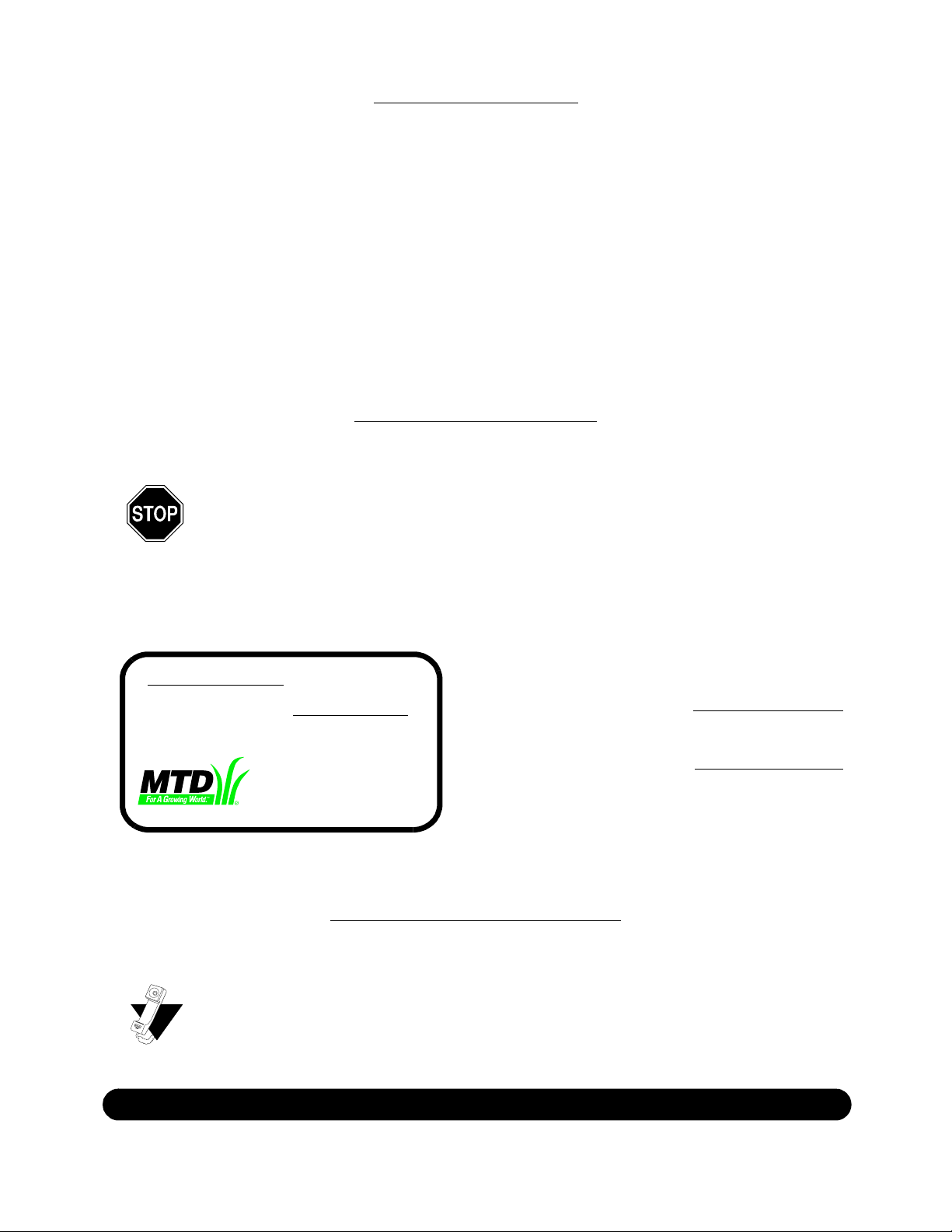
TABLE OF CONTENTS
Content Page
Important Safe Operation Practices...................................................................3
Slope Gauge......................................................................................................6
Assembling Your Lawn Mower...........................................................................7
Know Your Lawn Mower ....................................................................................9
Operating Your Lawn Mower .............................................................................9
Making Adjustments ..........................................................................................10
Maintaining Your Lawn Mower...........................................................................11
Troubleshooting.................................................................................................14
Parts List............................................................................................................16
FINDING MODEL NUMBER
This Operator’s Manual is an important part of your new lawn mower. It will help you assemble, prepare and
maintain the unit for best performance. Please read and understand what it says.
Before you start assembling your new equipment, please locate the model plate on the
equipment and copy the information from it in the space provided below. The information on
the model plate is very important if you need help from our Customer Support Department or
an authorized dealer.
• You can locate the model number by standing at the operating position and looking down at the rear
of the mower deck. A sample model plate is explained below. For future reference, please copy the
model number and the serial number of the equipment in the space below.
(Model Number)
(Serial Number)
MTD PRODUCTS INC
CLEVELAND, OHIO 44136
Copy the model number here:
Copy the serial number here:
CALLING CUSTOMER SUPPORT
If you have difficulty assembling this product or have any questions regarding the controls, operation or
maintenance of this unit, please call the Customer Support Department.
Call 1- (330) 220-4MTD (4683) or 1- (800)-800-7310 to reach a Customer Support
representative. Please have your unit’s model number and serial number ready when you
call. See previous section to locate this information. You will be asked to enter the serial
number in order to process your call.
For more details about your unit, visit our website at www.mtdproducts.com
2
Page 3

SECTION 1: IMPORTANT SAFE OPERATION PRACTICES
WARNING: This symbol points out important safety instructions which, if not followed, could
endanger the personal safety and/or property of yourself and others. Read and follow all instructions in
this manual before attempting to operate this machine. Failure to comply with these instructions may
result in personal injury. When you see this symbol - heed its warning.
WARNING: Engine Exhaust, some of its constituents, and certain vehicle
components contain or emit chemicals known to State of California to cause cancer
and birth defects or other reproductiv e harm.
DANGER: This machine was built to be operated according to the rules for safe operation in this
manual. As with any type of power equipment, carelessness or error on the part of the operator can
result in serious injury. This machine is capable of amputating hands and feet and throwing objects.
Failure to observe the following safety instructions could result in serious injury or death.
General Operation
1. Read this operator’s manual c arefully in its e ntirety
before attempting to a ssembl e this mac hine. Read,
understand, and fo llow al l instruct ions on th e machin e
and in the manua l(s) befo re operatio n. Be com pletely
familiar with the c ontrols and the proper use o f this
machine before operating it. Keep this manual in a safe
place for future and re gular refe rence and for ordering
replacement parts.
2. This machine is a precision piece of power equipment,
not a plaything. Th erefore, exercise extre me caution at all
times. Your unit has been designed to p erform one job: to
mow grass. Do not u se it for any other purpose.
3. Never allow childre n under 14 y ears old to operate this
machine. Children 14 years old and over should rea d and
understand the op eration in struction s and sa fety rules i n
this manual and should be trained and sup ervised b y a
parent. Only respons ible indiv iduals who a re famili ar with
these rules of s afe operati on shoul d be allow ed to us e
this machine.
4. Thoroughly inspect the area wh ere the equipment i s to
be used. Remove al l stones, sticks , wire, bones, toys and
other foreign objec ts which could b e tripped over or
picked up and th rown by th e blade. T hrown obje cts can
cause serious persona l injury . Plan your m owing patte rn
to avoid discharge of materi al toward ro ads, sid ewalks,
bystanders and the like. Also, avo id discharging material
against a wall or obstructi on which m ay cause
discharged material to ri cochet back tow ard the operator.
5. To help avoid blade contact or a thro wn object injury, stay
in the operator zo ne behind the hand les and keep
children, bystanders , helpers a nd pets a t least 7 5 feet
from the mower wh ile it is in opera tion. Stop machine if
anyone enters the area.
6. Always wear safet y glasses or safety goggles during
operation and while performing an adjustment or repair to
protect your eyes. T hrown ob jects whi ch ricochet can
cause serious inj ury to the eyes.
7. Wear sturdy, rough-sol ed work shoes a nd close-fi tting
slacks and shirts . Shirts an d pants that cove r the a rms
and legs and steel -toed shoes are recommend ed. Never
operate this machin e in bare feet, san dals, sl ippery or
light weight (e.g. c anvas) sho es.
8. Do not put hands o r feet near rotating p arts or un der the
cutting deck. Con tact with the blade can am putate ha nds
and feet.
9. A missing or damaged discharg e cover can cause b lade
contact or thrown ob ject inj uries.
10. Many injuries occur as a resul t of the mower being pul led
over the foot during a fall caused by slipping or tripping.
Do not hold on to the mower if you are falling; releas e the
handle immediately .
11. Never pull the mowe r back to ward yo u while y ou are
walking. If you mus t back th e mower aw ay from a wall or
obstruction first look down and behind to avoid trippi ng
and then follow these st eps:
a. Step back from the mower to fu lly exte nd your
arms.
b. Be sure you are well balance d with sure footing.
c. Pull the mower back slowly, no more than half way
toward you.
d. Repeat these steps as neede d.
12. Do not operate the m ower whi le under t he influe nce of
alcohol or drugs.
13. Do not engage the self-pro pelled mechan ism on uni ts so
equipped while st arting engine.
14. The blade control handle is a safety device. Never
attempt to bypas s its operat ion. Doi ng so m akes the
safety device inoperat ive and may result in per sonal
injury through contact with the rotating blade. The blade
control handle m ust opera te easily i n both di rections and
automatically return to the di sengaged positio n when
released.
15. Never operate the mow er in wet gra ss. Always be sure of
your footing. A s lip and fa ll can c ause se rious person al
injury. If you fee l you are lo sing yo ur footi ng, releas e the
blade control han dle immedi ately an d the bla de will stop
rotating within three second s.
16. Mow only in daylig ht or in goo d artifici al light. Wa lk, never
run.
17. Stop the blade wh en crossin g gravel drives, wa lks or
roads.
18. If the equipment should start to vibrate abnormally, stop
the engine and check immedia tely for the cause .
Vibration is gener ally a warn ing of tro uble.
19. Shut the engine off and wa it until t he bla de come s to a
complete stop before removi ng the grass catcher or
3
Page 4

unclogging the c hute. The cutting b lade co ntinues t o
rotate for a few second s after the engine is shut off.
Never place any part of the body in the blade area until
you are sure the b lade has s topped rot ating.
20. Never operate mower wi thout prop er trail shield,
discharge cover , grass c atcher, blad e cont rol handle or
other safety protec tive dev ices in p lace and working.
Never operate mower with damaged sa fety devices.
Failure to do so, ca n result i n persona l injury .
21. Muffler and engine beco me hot and can cause a burn. Do
not touch.
22. Only use parts and accessories made for this machine by
the manufacturer. F ailure to do so, c an result in perso nal
injury.
23. If situations occur which are not covered in this manua l,
use care and good judgment. Cont act your dealer for
assistance. Tel ephone 1- 800-800-731 0 for the name of
your nearest dealer.
Slope Operation
Slopes are a major f actor re lated to slip and fall accid ents
which can result in seve re inju ry. Opera tion on s lopes
requires extra cauti on. If you feel une asy on a slope, do not
mow it. For your safet y, use th e slope gauge in cluded a s part
of this manual to measure s lopes before o perating t his unit on
a sloped or hill y area. If the slop e is greater than 15 d egrees,
do not mow it.
Do:
1. Mow across the face of sl opes; never up and down.
Exercise extreme cauti on when changing d irection on
slopes.
2. Watch for holes, ru ts, rocks, hidden ob jects, o r bumps
which can cause you to s lip or tri p. Tall grass c an hide
obstacles.
3. Always be sure of your footi ng. A slip and fall can ca use
serious personal in jury. If y ou feel y ou are lo sing yo ur
balance, release the blade c ontrol han dle imm ediately ,
and the blade w ill stop rotating wi thin 3 se conds.
Do Not:
1. Do not mow near d rop-offs, d itches o r embank ments,
you could lose your foot ing or bal ance.
2. Do not mow slopes greater th an 15 degre es as shown on
the slope gauge.
3. Do not mow on wet grass. U nstable footing c ould cau se
slipping.
Children
Tragic accident s can occu r if the o perator is not al ert to the
presence of childre n. Chil dren are of ten attrac ted to the
mower and the mowi ng activ ity. They do not unde rstand the
dangers. Never assum e that c hildren wil l remain where you
last saw them.
1. Keep children out of t he mow ing area a nd under the
watchful care of a responsi ble adul t other than the
operator.
2. Be alert and turn mower off if a child enters the area.
3. Before and while moving backw ards, look behin d and
down for small ch ildren.
4. Use extreme care when approaching blind corners,
doorways, shrubs, tree s, or othe r objects th at may
obscure your vision of a child who may run into the
mower.
5. Keep children away from hot or running engines. They
can suffer burns from a hot muffler.
6. Never allow children u nder 14 y ears old to operate a
power mower. Child ren 14 ye ars old a nd over shou ld
read and understand t he ope ration inst ructions a nd
safety rules in this manual and sho uld be tra ined and
supervised by a parent.
Service
Safe Handling Of Gasoline:
1. To avoid personal injury or property damage use extre me
care in handling gasolin e. Gasol ine is e xtremely
flammable and the v apors are explosiv e. Serious
personal injury c an occur w hen gas oline is spilled o n
yourself or your c lothes which can ignit e.
2. Wash your skin and chan ge clothe s imme diatel y.
3. Use only an appro ved gaso line con tainer.
4. Never fill contain ers insi de a veh icle or o n a truck or
trailer bed with a p lastic liner. Al ways place containers o n
the ground away from your v ehicle b efore filli ng.
5. When practical, re move ga s-powered e quipment from
the truck or tr ailer and ref uel it on the ground. If this is not
possible, then re fuel such e quipment on a trailer with a
portable container, ra ther than from a gasoli ne dispenser
nozzle.
6. Keep the nozzle i n contact w ith the rim of the fuel tank or
container opening a t all times until fue ling is complete. D o
not use a nozzle l ock-open device.
7. Extinguish all ciga rettes, c igars, pip es and othe r sources
of ignition.
8. Never fuel machin e indoors becaus e flammable vapors
will accumulate in the area.
9. Never remove gas ca p or a dd fuel wh ile the e ngine is hot
or running. Allow e ngine to c ool at l east two m inutes
before refueling.
10. Never over fill fue l tank. Fi ll tank to no mor e than ½ inch
below bottom of fil ler neck to provi de space for fuel
expansion.
11. Replace gasoline cap and tighten s ecurely.
12. If gasoline is spi lled, wi pe it off the engin e and
equipment. Move unit to a nother area. Wait 5 minute s
before starting the en gine.
13. Never store the machine or fuel cont ainer inside whe re
there is an open flame, spark or pilot light as on a w ater
heater, space heater , furnace ,cloth es dryer or other g as
appliances.
14. To reduce fire hazard, k eep mower free of gras s, leav es,
or other debris bui ld-up. C lean up o il or fue l spillage and
remove any fuel soaked debris .
15. Allow a mower to coo l at least 5 minutes before stori ng.
General Service:
1. Never run an engine indoors or in a poorly ven tilated
area. Engine exhau st conta ins carb on monox ide, an
odorless and dea dly gas .
2. Before cleaning, re pairing, o r inspec ting, mak e certain
the blade and al l moving p arts hav e stopped . Disconn ect
the spark plug wir e and ground aga inst the engine to
prevent unintended starting .
3. Check the blade a nd engine mountin g bolts at frequ ent
4
Page 5
intervals for proper tigh tness. Also, visu ally inspec t blade
for damage (e.g., b ent, crack ed, worn) R eplace bl ade
with the original equip ment manufacture’s (O. E.M.) blade
only, listed in this manual . “Use of p arts which do not
meet the original equipment specific ations m ay lead to
improper performance and com promise sa fety!”
4. Mower blades are s harp and can cut. Wrap the b lade or
wear gloves, and u se extra caution when se rvicing the m.
5. Keep all nuts, bolts, and screws tight to be sure the
equipment is in safe work ing cond ition.
6. Never tamper with safety devices. Check their proper
operation regularly.
7. After striking a foreign o bject, stop the engine, dis connect
the spark plug wire and grou nd agains t the engine.
Thoroughly inspect the mower for any da mage. R epair
the damage before st arting and operat ing the mow er.
8. Never attempt to ma ke a w heel or c utting hei ght
adjustment while the engin e is runn ing.
9. Grass catcher componen ts, discharge cover, and trail
shield are subject to wear and dama ge which could
expose moving pa rts or allo w objec ts to be thrown. For
safety protection, frequentl y check componen ts and
replace immediatel y with original equipm ent
manufacturer’s (O.E.M .) parts only , listed in this ma nual.
“Use of parts which do not m eet the ori ginal eq uipment
specifications ma y lead t o imprope r performan ce and
compromise safety!”
10. Do not change t he engine governor setting o r overs peed
the engine. The go vernor co ntrols th e maxim um safe
operating speed o f the engi ne.
11. Maintain or replac e safety and ins truction labels, a s
necessary.
12. Observe proper disp osal law s and regulation s. Improp er
disposal of flui ds and mate rials ca n harm th e
environment.
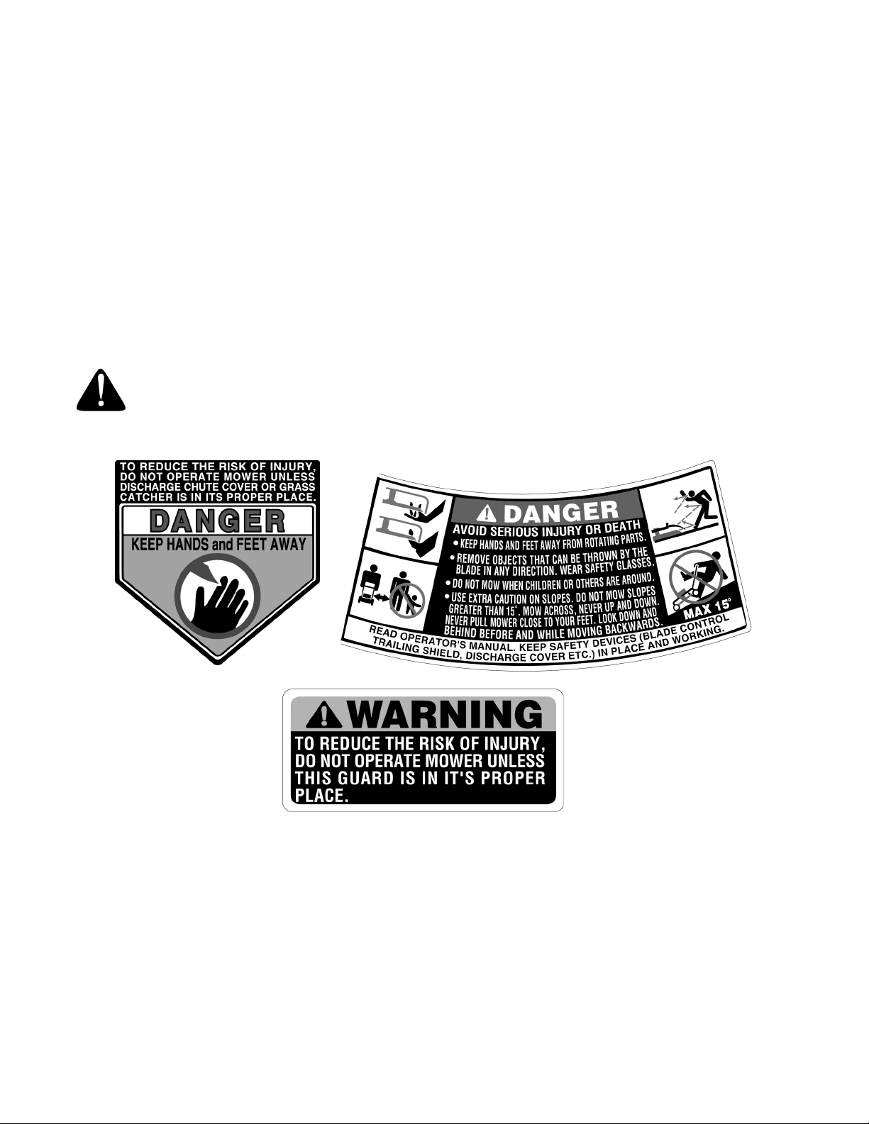
WARNING - YOUR RESPONSIBILITY: Restrict the use of th is power mac hine to p ersons wh o read,
understand and fo llow th e warnings and ins tructions in this manual a nd on the mach ine.
NOTE: Not all safety labels shown may apply to your lawn mower.
5
Page 6
SECTION 2: SLOPE GAUGE
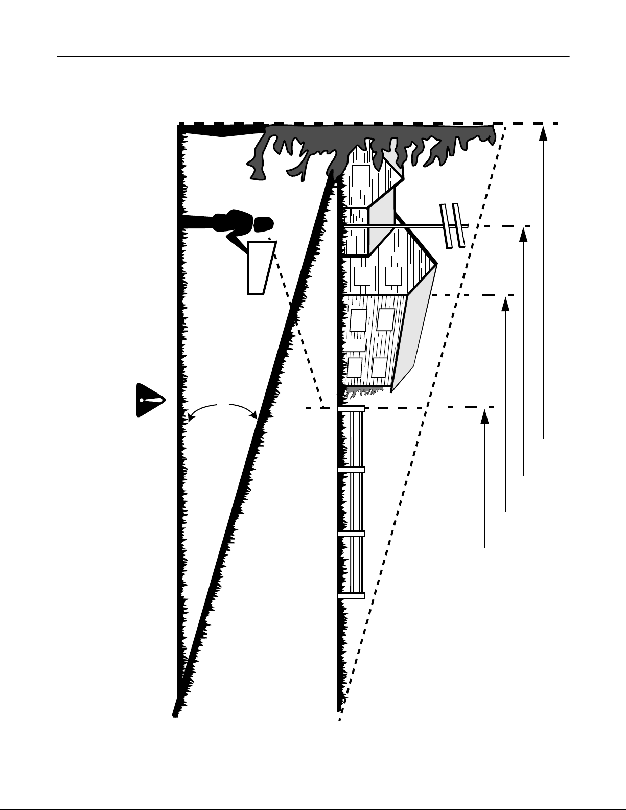
Use this page as a guide to determine slopes where you may not operate safely. Do not operate your lawn mower
on such slopes.
Operate RIDING mowers up and down slopes, never across the face of slopes.
Operate WALK-BEHIND mowers across the face of slopes, never up and down slopes.
Do not mow on inclin es with a s lo pe i n e xces s of 1 5 de gr ees ( a r ise o f approximately 2-1/2 f eet every 10 feet). A ridi ng m owe r could
overturn and cause serio us injur y. If oper ating a walk-be hind mo wer on suc h a slope, i t is ex tremely diffic ult to maint ain your footing
and you could slip, resulting in serious injury.
F
O
L
D
O
N
D
O
T
T
E
D
L
I
N
E
,
R
E
P
R
E
S
E
N
T
I
N
G
A CORNER OF A BUILDING
OR A FENCE POST
SIGHT AND HOLD THIS LEVE L WITH A VERTICAL TREE
A POWER POLE
WARNING
15°
A
1
5
°
S
L
O
P
E
6
Page 7
SECTION 3: ASSEMBLING YOUR LAWN MOWER
IMPORT ANT :
in the engine. Be certain to service engine with gasoline
and oil as instructed in the separate engine manual
before operating your mower.
NOTE: Reference to right or left hand side of the mower
is observed from the operating position.
This unit is shipped without gasoline or oil
Removing Unit From Carton
• Remove staples, break glue on top flaps, or cut tape
at carton end and peel along top flap to open carton.
• Remove loose parts if included with unit (i.e.,
operator’s manual, etc.)
• Cut along corners, lay carton down flat, and remove
packing material.
• Roll or slide unit out of carton and check carton
thoroughly for loose parts.
Loose Parts in Carton
• Grass Bag
• Side Discharge Chute
• Hardware Pack
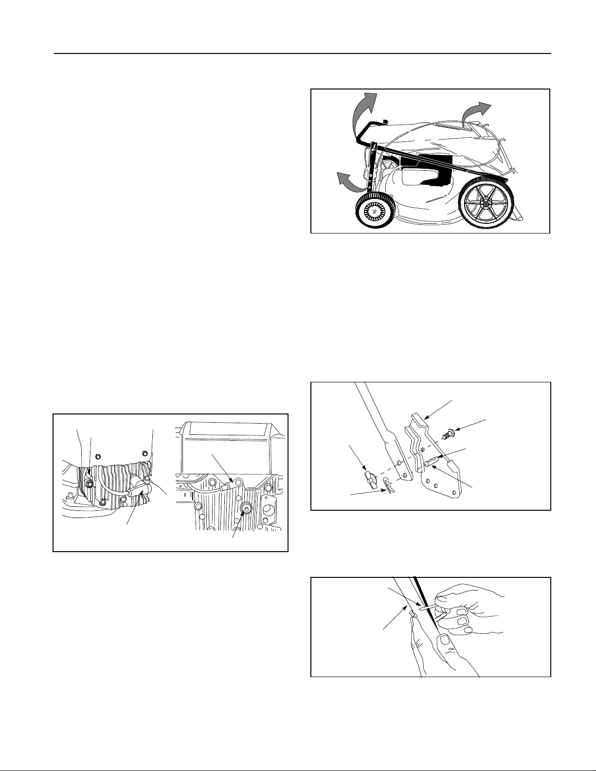
Disconnecting Spark Pl ug Wire
Before setting up your lawn mower, disconnect the spark
plug wire from the spark plug and ground against the
engine. See Figure 1.
Bolt
Spark Plug
Wire
Figure 2
• Remove the hairpin clips from the outer hole in the
weld pins on the handle mounting brackets. Using a
pair of pliers, squeeze one leg of the lower handle
against the handle mounting bracket. Insert the
hairpin clip into the inner hole on the weld pin.
Repeat on the other side. See Figure 3.
• After moving the hairpin clip, insert the carriage bolt
from hardware pack in the upper hole on the handle
mounting bracket and secure with plastic wing nut
from the hardware pack. Repeat on other side.
Handle Mounting
Bracket
Carriage Bolt
Wing Nut
Insert Ha ir p in
Clip
Spark
Plug Wire
Spark Plug
Figure 1
Setting Up Y our Lawn Mower
Assembling Handle
• Lift up and pull back on the upper handle to raise the
handle into the operating position. Make certain the
lower handle is seated securely into the handle
bracket assemblies. Tighten the wing nuts on each
side of the handle (carriage bolts must be seated
properly into the handle). See Figure 2.
NOTE: Your mower is shipped with the handle in the
higher position. If you wish to lower the height of the
handle, refer to the Adjustment Section at this time.
Hairpin
Clip
Figure 3
• Fasten the cable to the lower handle with the two
cable ties found on the lower handle. Pull the cable
ties tight and trim off the excess.
See Figure 4.
Cable Tie
Lower
Handle
Figure 4
7
Weld Pin
Page 8
Attaching Starter Rope
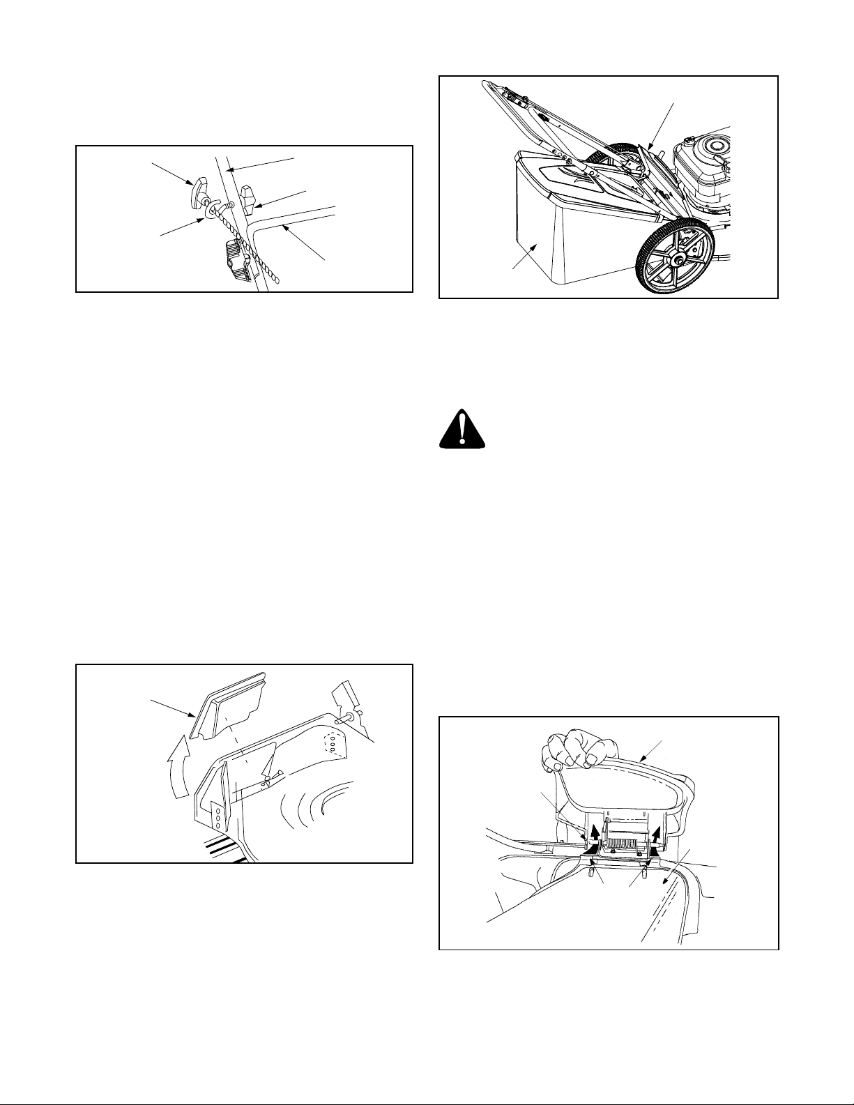
• The rope guide is attached to the right side of upper
handle. Loosen the wing nut which secures the
rope guide. See Figure 5.
Starter
Rope
Rope
Guide
Upper Handle
Wing Nut
Lower
Handle
Discharge Door
Grass Bag
Figure 5
• With the spark plug wire disconnected and
grounded, hold the blade control handle against the
upper handle, and pull the starter rope out of the
engine. Release the blade control handle. Slip the
starter rope into the rope guide. Tighten the wing
nut.
Attaching Grass Catcher To Mower
NOTE: The mu lching baffle, if so equip ped, is already
in place on the mower for shipping purposes. Your lawn
mower may be equipped with both a mulching baffle
and a mulching plug. While the mulching baffle is
located at the rear of the mower, the mu lching plug is
located on the right side of the cutting deck. Do not
remove the mulching plug from the mower even when
you are not mulching the grass.
• To remove the mulching baffle, lift the rear discharge door on the mower. Remove the mulching
baffle. See Figure 6.
Mulching
Baffle
Figure 7
• To remove the grass catcher, lift the rear discharge
door on the mower, lift the grass catcher up and off
the pivot rod. Reinstall the mulching baffle and
release the rear discharge door.
WARNING: Never operate the mower
unless the hooks on the grass catcher are
firmly seated on the chute pivot rod, and
the rear discharge door rests firmly
against the top of the grass catcher.
Converting To Side Dischar ge
If your unit is equipped with a side discharge chute, you
can convert to a side discharge mower as follows:
• Lift the rear discharge door and install the mulching
baffle. See Figure 6.
• On the side of the mower, lift the mulching plug and
slide the two hooks of the side discharge chute
under the hi nge pin on the mulching pl ug assembly.
Lower the side mulching plug. See Figure 8.
• Do not remove the side mulching plug at any time,
even when you are not mulching.
Figure 6
IMPORT ANT :
Make sure cables are routed to the
outside of the handle so they are not in the way when
attaching the grass catcher.
• Lift the rear discharge door on the mower.
• Place the hooks, found on both sides of the grass
catcher frame, over the chute door pivot rod at the
rear of the mower. Release the rear discharge door.
See Figure 7.
Mulching Plug
Hinge Pin
Deflector
Hook
Figure 8
8
Page 9
SECTION 4: KNOW YOUR LAWN MOWER
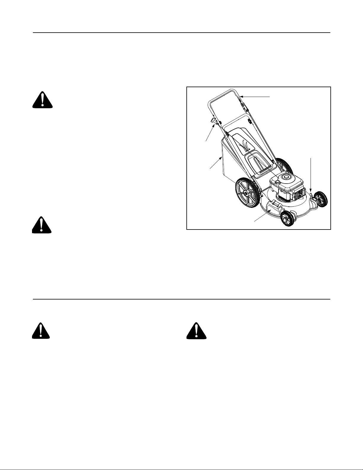
Read this operator’s manual and safety rules before
operating your lawn mower. Compare the illustration in
Figure 9 with your lawn mower to familiarize yourself
with the location of various controls and adjustments.
Save this manual for future reference.
WARNING: The operation of any lawn
mower can result in foreign objects being
thrown into the eyes, which can damage
your eyes severely. Always wear safety
glasses while operating the mower, or
while performing any adjustments or
repairs on it.
Recoil Starter
The recoil starter is attached to the right handle. Stand
behind the unit and pull the recoil starter to start the
unit. See Figure 9.
Blade Control Handle
The blade control handle is located on the upper handle
of the mower. The blade control handle must be
depressed in order to operate the unit. Release blade
control handle to stop engine and blade. See Figure 9.
Grass Catcher
The grass catcher, located at the rear of the mower, is
used to bag the grass clippings for disposal at another
site. Once the bag is full, it has to be removed from the
mower and emptied before any further mowing.
Recoil
Starter
Grass
Catcher
Blade Control
Handle
Cutting Height
Adjustment Lever
WARNING: This blade contro l mechanism
is a safety device. Never attempt to bypass
its operations.
Cutting Height Adjustment Levers
These levers are located on each wheel and are used
to adjust the cu tting hei ght. Thes e levers hav e to be at
the same relative position to ensure uniform cut.
See Figure 9.
Mulching Plug
Both the mulching baffle and the mulching plug are
used only for mulching purposes. Instead of collecting
the grass clippings in a grass catcher, some mower
models have the option of recirculating the clippings
back to the lawn.
SECTION 5: OPERATING YOUR LAWN MOWER
WARNING: Keep hands and feet away from
chute area on the cutting deck. The
operation of any lawn mower can result in
foreign objects being thrown into the eyes,
which can result in severe eye damage.
Always wear safety glasses or eye shields.
NOTE: For shipping pur poses your mower is set with
the wheels in a low cutting height position. For best
results raise the cutting position until it is determine
which height is best for your lawn. See the Adjustment
Section for details.
Gas and Oil Fill-Up
Service the engine with gasoline and oil as instructed in
the separate engine manual packed with your mower.
Read instructions carefully.
Starting Engine
• Attach spark plug wire to spark plug. Make certain
• Prime engine as instructed in the separate engine
• Your lawn mower may be equipped with a constant
Never fill fuel tank indoors with engine
running or until the engine has been
allowed to cool for at least two minutes
after running.
the metal c ap on the end o f the spar k plug i s
fastened securely over the metal tip on the spark
plug.
manual packed with your unit.
speed throttle, which is set at full throttle for best
performance.
Mulching Plug
Figure 9
9
Page 10
• Stand behind the mower and squeeze the blade
control handle against the upper handle.
• Grasp recoil starter handle and pull rope out slowly
until engine reaches the start of compression cycle
(rope will pull slightly harder at this point). Let the
rope rewind slowly. Pull rope with a rapid,
continuous, full arm stroke. Keeping a firm grip on
the starter handle, let the rope return to the starter
slowly.
Using Y our Lawn Mow er
Be sure that the lawn is clear of stones, sticks, wire, or
other obj ects wh ich could d amage the la wn mo wer or
the engine. Such objects could be accidently thrown by
the mower in any di rection and cause serious pers onal
injury to the operator and others.
For best results, do not cut wet grass because it tends
to stick to the underside of the mower, preventing
proper discharge of grass clippings, and could cause
you to slip and fall. New grass, thick grass, or wet grass
may require a narrower cut.
For a healthier lawn, never cut off more than one-third
of the total length of the grass. Your lawn should be cut
in the fall as long as there is growth. This mower is
designed to be operated at full throttle to give you the
best cut and do the most effective job of mowing or
mulching.
WARNING: If you strike a foreign object,
stop the engine. Remove wire from the
spark plug, thoroughly inspect the mower
for any damage, and repair the damage
before restarting and operating the
mower. Extensive vibration of the mower
during operation is an indication of
damage. The unit should be promptly
inspected and repaired.
Mulching
For effective mulching, do not cut wet grass because it
tends to stick to the underside of the deck, preventing
proper mulching of grass clippings. New or thick grass
may require a narrower cut. The ground speed should
be adjusted to the condition of the lawn. If mowing has
been delayed and the grass has been allowed to grow
in excess of 4”, mulching is not recommended. Mow
using the side discharge to reduce the grass height to 3
1/4” maximum before mulching.
SECTION 6: MAKING ADJUSTMENTS
WARNING: Do not at any time make any
adjustments without first stopping engine
and disconnecting spark plug wire.
Handle Height Adjustment
Your mower is shipped with the handle in the higher
height position. To lower the height proceed as follows:
• Remove the start er ro pe fr om the rope g uide .
• Remove the upper handle by removing the hand
knobs and carriage bolts. Lay the upper handle out
of the way, being careful not to bend or kink the
cables.
• Remove the hairpi n clip s from the w eld pin s on t he
handle brackets and remove the wing nuts and
carriage bolts from the upper hole on the handle
mounting bracket. Press out on the legs of the
lower handle and remove lower handle from the
mower.
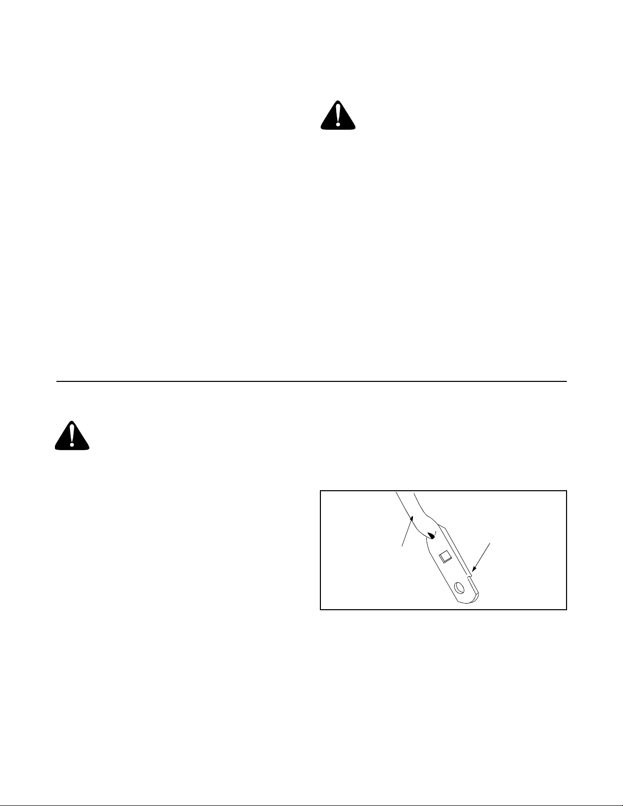
• Turn lower handle around so the notch on the
bottom of the lower handle is facing forward.
See Figure 10.
• Reassemble, placing the bottom holes in the
handle over the weld pins in the handle mounting
bracket.
• Place the hairpin clips in the inner holes in the weld
pins and insert the carriage bolts the upper hole on
the handle mounting bracket and secure with
plastic wing nuts.
• Reassemble the upper handle to the lower handle.
• Attach the starter rope as instructed in the
Assembly Section.
Notch
Lower Handle
Figure 10
Cutting Height Adjustment
An adjusting plate and spring lever at each wheel
position provid es cut ting heig ht adju stme nt. Eac h
adjusting plate has assorted height positions. When the
spring lever is moved from one location to another the
height of cut will be changed. Simply depress the lever
towards wheel and move lever assembly to desired
position. See Figure 11.
10
Page 11
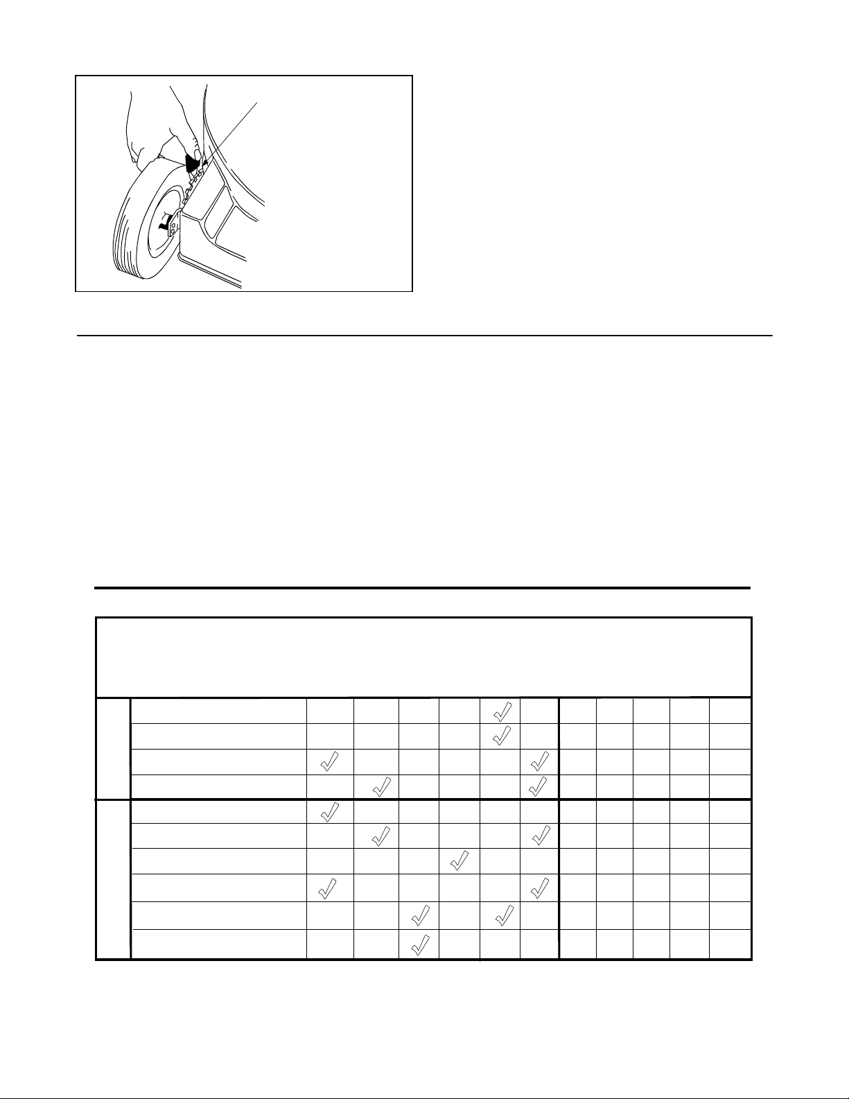
Height Adjustment
Lever
IMPORT ANT :
relative position. For rough or uneven lawns, move the
height adjustment lever to a higher position. This will
All wheels must be placed in the same
help stop scalping of the grass.
Engine Adjustments
See the separate engine manual packed with your unit
for adjustments to the engine.
Figure 11
SECTION 7: MAINTAINING YOUR LAWN MOWER
General Recommendations
• Always observe safety rules when performing any
maintenance.
• The warran ty on this lawn m ower does n ot co ver
items that have been subjected to operator abuse
or negligence. To receive full value from the
warranty, operator must maintain the lawn mower
as instructed in this manual.
• Changing of engine governed speed will void
engine warranty.
Customer Responsibilities
e
s
u
MAINTENANCE
SCHEDULE
Lubricate Wheels
T
C
Lubricate Blade Control
U
D
Clean Deck
O
R
P
Blade Care
h
c
a
e
r
e
t
f
A
r
e
v
E
• Some adjustm ents will have to be m ade
periodically to maintain your unit properly. All
adjustments in the Making Adjustments section of
this manual should be checked at least once each
season.
• Periodically check all fasteners and make sure
these are tight.
• Follow the maintenance schedule under Customer
Responsibilities to get quality performance from
your lawn mower.
s
n
s
s
r
u
o
h
5
2
y
u
o
h
0
5
y
r
e
v
E
E
r
r
u
s
o
h
0
0
1
y
r
e
v
a
e
s
a
e
c
n
B
O
e
o
g
a
r
o
t
s
e
r
o
f
e
SERVICE
DATES
Check Oil
Change Oil
E
Replace Ai r Filter
N
I
G
Clean Engine
N
E
Check Spark Plug
Check Spark Arrester (if any)
11
Page 12
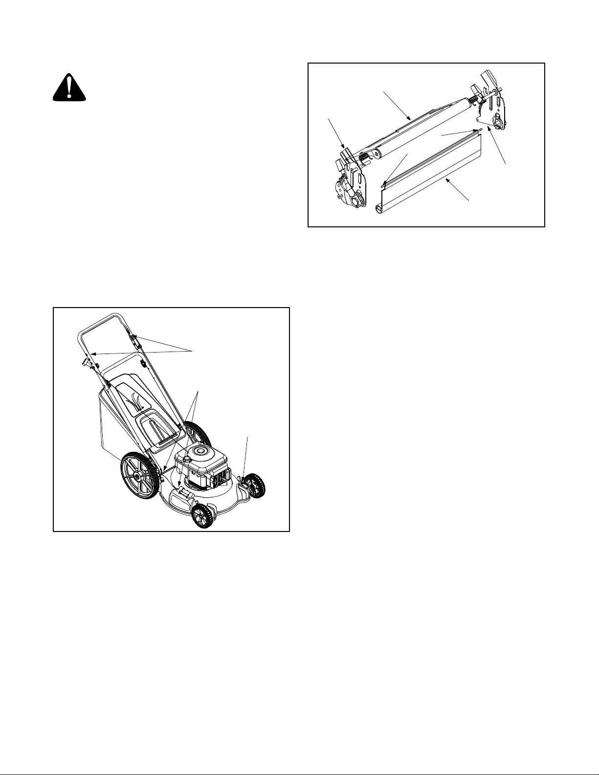
Lubrication
Always stop engine and disconnect spark
plug wire before cleaning, lubricating or
doing any kind of service work on the lawn
mower.
Blade Control: Lubricate the pivot points on the blade
control handle and the brake cable at least once a
season with light oil. The blade control must operate
freely in both directions. See Figure 12.
Rear & Side Discharge Doors: The torsion springs
and pivot points should be lubricated periodically with
light oil to prevent any rust or binding. Door must work
freely.
Wheels: The wheels require no lubrication. However, if
the wheels are removed for any reason, lubricate the
surface of the axle bolt and the inner surface of the
wheel with light oil. Engine oil may also be used.
Engine: Follow engine manual for instruction and
schedule of lubrication.
Lubricate
Lubricate
Lubricate
Figure 12
Maintenance
NOTE: When tippin g the unit or emp tying the fuel tank
keep the air cl eaner side of engine up. Never t ip the
mower more than 90 degrees and do not leave the
mower tipped for any length of time. O il can drain into
the upper part of the engine causing a starting problem.
Replacing Rear Flap
• To remove rear flap, cut off the flat end of the wire
rod which secures it to the deck. See Figure 13.
• Attach the new flap and new rod to deck, bending
the ends of the new rod over to secure to deck
Rear Discharge
Door
Handle
Bracket
od
R
e
r
i
W
Handle
Bracket
Rear Flap
Figure 13
Engine
Refer to the separate engine manual for all engine
maintenance instructions.
• Maintain engine oil as instructed in the separate
engine manual packed with your unit.
• Service air cleaner every 25 hours under normal
conditions. Poor engine performance and flooding
usually indicate that the air cleaner should be
serviced. To service the air cleaner, refer to the
separate engine manual packed with your unit.
• The spark plug should be cleaned and the gap
reset once a season. Spark plug replacement is
recommended at the start of each mowing season.
• Clean the engine regularly with a cloth or brush.
Keep the cooling system (blower housing area)
clean to permit proper air circulation which is
essential to engine performance and life. Be certain
to remove all grass, dirt, and combustible debris
from muff ler area.
Deck
The underside of the mower deck should be cleaned
after eac h use to pr even t a bu ildup of gr ass c lippi ngs,
leaves, dirt, or other matter. If this debris is allowed to
accumulate, it will invite rust and corrosion, and may
prevent proper mulching, discharge, or bagging. The
deck may be cleaned by tilting the mower and scraping
clean with a suitable tool (make certain the spark plug
wire is disconnected).
IMPORT ANT :
pressure washer or garden hose to clean your unit. The
use of water will result in shorten life and reduce
serviceability.
We do not recommend the use of a
Cutting Blade Removal, Replacement, and Sharpening
• When removing the cutting blade for sharpening or
replacement, protect your hands with a pair of
heavy gloves or use a heavy rag to hold the blade.
• Remove the bolt and the blade bell support which
hold the blade and the blade adapter to the engine
crankshaft. See Figure 14.
12
Page 13
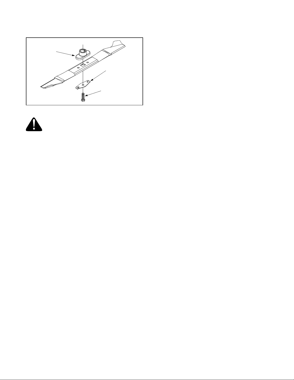
• Remove the blade and the adapter from the
crankshaft.
Blade
Adapter
Blade Bell
Support
Hex Bolt
• Slide the blade adapter onto the engine crankshaft.
• Place the blade on the adapter. Be certain the
blade is aligned and seated on the blade adapter
flanges.
• Place blade bell support on blade. Make sure the
notches on the blade bell support are aligned with
small holes in the blade.
• Replace hex bolt and tighten hex bolt to torque: 450
in. lbs. min., 600 in. lbs. max.
NOTE: To ensure safe operation of your mower, the
blade bolt must be checked periodically for correct
torque.
Figure 14
WARNING: Periodical ly inspect the blade
adapter for cracks, especially if you strike
a foreign object. Replace when necessary.
When sharpening the blade, follow the original angle of
grind as a guide. It is extremely important that each
cutting edge receives an equal amount of grinding to
prevent an unbalanced blade. An unbalanced blade will
cause excessive vibration when rotating at high
speeds. It may cause damage to the mower, and could
break causing personal injury.
The blade can be tested by balancing it on a round
shaft screwdriver. Remove metal from the heavy side
until it balances evenly. It is recommended that the
blade always be removed from the adapter when
testing for balance. Before reinstalling the blade and
the blade adapter to the unit, lubricate the engine
crankshaft and the inner surface of the blade adapter
with light oil.
• Be sure to install the blade with the side of the
blade marked “Bottom” (or with part number) facing
the ground when the mower is in the operating
position.
Storing your Lawn Mower
The following steps should be taken to prepare your
lawn mower for storage.
• Clean and lubricate mower thoroughly as described
in the lubrication instructions.
IMPORT ANT :
pressure washer or garden hose to clean your unit.
• Refer to engine manual for correct engine storage
instructions.
• Coat mower’s cutting blade with chassis grease to
prevent rusting.
• Store mower in a dry, clean area. Do not store next
to corrosive materials, such as fertilizer.
NOTE: When storing any type of power equipment in a
poorly ventilated or metal storage shed, care should be
taken to rust-proof the equi pment. Using a light oil or
silicone, coat the equipment, e specially cab les and all
moving parts.
We do not recommend the use of a
13
Page 14

SECTION 8: TROUBLESHOOTING
Problem Cause Remedy
Engine fails to start 1. Blade control handle disengaged.
2. Spark plug wire disconnected.
3. Fuel tank empty or stale fuel.
4. Blocked fuel line.
5. Faulty spark plug.
6. Engine flooded
Engine runs er ratic 1. Spa rk plug wir e loose.
2. Blocked fuel line or stale fuel.
3. Vent in gas plugged.
4. Water or dirt in fuel system.
5. Dirty air cleaner.
6. Carburetor out of adjustment.
Engine overheats 1. Engine oil level low.
2. Air flow restricted.
3. Carburetor not adjusted properly.
Occasional skip (hesitates)
at high speed
Idles poorly 1. Spark plug fouled, faulty or gap too
Excessive vibration 1. Cutting blade loose or unbalanced.
Mower will not mulch grass 1. Wet grass.
Uneven cut 1. Wheels not positioned correctly.
NOTE: For repairs beyond the minor adjustments above, contact your local authorized service dealer.
1. Spark plug gap too close. 1. Adjust gap to .030”.
wide.
2. Carburetor improperly adjusted.
3. Dirty air cleaner.
2. Bent cutting blade.
2. Excessively high grass.
3. Dull blade.
2. Dull blade.
1. Engage blade control handle.
2. Connect wire to spark plug.
3. Fill tank with clean, fresh gasoline.
4. Clean fuel line.
5. Clean, adjust gap, or replace.
6. Wait a few minutes to restart, but do not
prime.
1. Connect and tighten spark plug wire.
2. Clean fuel line; fill tank with clean, fresh
gasoline
3. Clear ve nt.
4. Drain fuel tank. Refill with fresh fuel.
5. Clean air cleaner.
6. Adjust carburetor.
1. Fill crankcase with proper oil.
2. Remove blower housing and clean.
3. Adjust carburetor.
1. Reset gap to .030” or replace spark
plug.
2. Adjust carburetor.
3. Clean air cleaner.
1. Tighten blade and adapter. Balance
blade.
2. Replace blade.
1. Do not mow when grass is wet; wait
until later to cut.
2. Mow once at a high cutting height, then
mow again at desired height or make a
narrower cutting path.
3. Sharpen or replace blade.
1. Place all four wheels in same height
position.
2. Sharpen or replace blade.
14
Page 15

Notes
15
Page 16
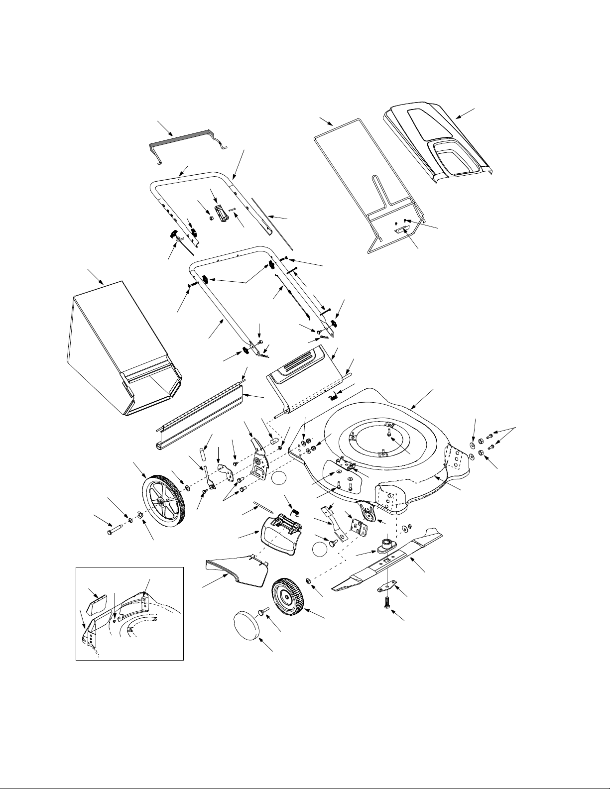
Model Series 540
18
73
76
59
1
70
71
15
11
12
21
5
3
9
2
6
4
13
52
80
50
81
83
44
30
56
55
85
63
57
24
17
31
20
22
84
16
82
57
20
39
87
14
43
44
86
49
95
96
4
52
23
61
92
40
94
47
42
41
32
58
62
19
89
88
90
51
67
66
54
53
64
72
93
16
71
60
36
34
33
Page 17

Model Series 540
Ref.
No.
1. 747-0824 Control Handle Assembly
2. 710-1205 Rope Guide
3. 720-0279 Handle Knob
4. 710-1174 Curved Hd. Bolt 5/16-18 x 2”
5. 712-0324 Hex L-Nut 1/4-20 Thd.
6. 720-0314 Hand Knob
9. 710-1270 Screw 1/4-20 x 1.31
11. 749-0438C Upper Handle
12. 720-0295 Foam Grip †
13. 749-0907A Lower Handle
14. 726-0240 Cable Tie
15. 747-0995A Catcher Frame
16. 746-0550 Control Cable 39”
17. 746-0841 Throttle Cable 60” †
18. 664-0084 Grass Bag w/o log o
19. 731-0066 Hard Top w/ logo
20. 714-0104 Internal Cotter Pin
21. 746-0883 Throttle Housing w /o Lever
22. 682-3058 Handle Bracket Asse mbly - RH
23. 782-7599A Grass Bag Door
24. 750-0434 Spacer .375 OD x .5 0 ID x 1.0 2”
30. 732-0700 Wire Rod
31. 731-1236 Rear Flap
32. 753-0588 Blade Adapter Kit
33. 710-1044 Hex Bolt 3/8-24 x 1. 5”
34. 736-0524A Blade Bell Support
36. 742-0741 Mulching Blade
39. 736-0356 Bell Washer .39” I.D. x 1 .38”
40. 712-0130 Hex Lock Nut 3/8 -16
41. 15261A Height Adj. Plate
42. 15262B Pivot Bar
43. 732-0404 Spring Lever: Front Whee l
44. 738-0507B Shoulder Bolt .5” Dia. x .357”
47. 720-0190 Spring Lever Knob
49. 14578 Height Adj. Assembly Comp - RH
Part No. Part Description
647-0004 Deluxe Control Han dle
746-0737 Control Cable 51”
746-0847 Throttle Cable 42” †
664-0085 Grass Bag w/ logo, Yellow
664-0086 Grass Bag w/ logo, Red
731-0068 Hard Top w/o logo
682-3059 Handle Brkt Ass’y - LH (N ot Shown)
14579 Height Adj. Assembly Comp - LH
Ref.
No.
50. 17488A Pivot Bar - RH
51. 782-5002 Front Baffle
52. 712-0397 Wing Knob
53. 782-5003 Rear Baffle
54. 710-1017 Torx Mach. AB-Tap Scr.
55. 710-0896 Hex Washer Screw 1/4 -14 x .62 5
56. 682-3058 Handle Bracket Assembly —R.H.
57. 710-0703 Carriage Bolt, 1/4-20 x .75”
58. 782-0047 Deck 21”
59. 734-1860 Rear Wheel Ass’y 14 x 2
60. 734-1818 Front Wheel Ass’y. 8 x 2
61. 747-0996 Chute Door Pivot Ro d
62. 710-0654A Sems Screw TT 3/8-16 x 1
63. 682-7000 Mulching Plug
64. 731-1409 Chute Deflector
66. 782-5007A Rear Mulch Plug
67. 782-5004 Rear Mulch Baffle
70. 736-0182 Wave Washer
71. 736-0105 Spring Washer
72. 731-1426 Hub Cap †
73. 738-0481A Rear Axle Bolt
76. 736-0456 Flat Washer
80. 720-0312 Foam Grip
81. 732-0866 Height Adj. Lever
82. 712-3005 Hex Flange Lock Nut 3/8-16
83. 710-0514 Hex Cap Screw 3/8-16 x 1. 0
84. 732-0731 Torsion Spring
85. 747-0710 Hinge Pin
87. 736-0270 Bell Washer .265 x .75 x .062
88. 710-0216 Hex Screw 3/8-16 x .75
89. 736-0331 Bell Washer .39 x 1.1 3 x .062
90. 712-0798 Hex Nut 3/8-16
92. 732-0809 Torsion Spring
93. 738-0102 Front Axle Bolt
94. 782-7006 Hinged Mounting Bracket
95. 710-0896 Hex Screw 1/4-14 x .625
96. 782-9050 Mounting Bracket
Part No. Part Description
17489A Pivot Bar - LH
682-3059 Handle Bracket Assembly —L.H.
734-1864 Rear Wheel Ass’y. 14 x 1.8
734-1781 Front Wheel Ass’y 8 x 1.75
734-1841 Front Wheel Ass’y 8 x 1.7
734-1987 Front Wheel Assembly 8 x 1.8
† If Equipped
17
Page 18

18
Page 19

19
Page 20

MANUFACTURER’S LIMITED WARRAN TY FOR:
The limited warranty set forth below is given by MTD
PRODUCTS INC (“MTD”) with respect to new mercha ndise
purchased and used in the United States, its possessions
and territories.
MTD warrants this product against defects in material and
workmanship for a period of two (2) years commencing on
the date of original purc ha se an d w i ll, at its option, repair or
replace, free of charge, any part found to be defective in
material or workmanship. This limited warranty shal l only
apply if this product has been operated and maintained in
accordance with the Operator’s Manual furnished with the
product, a nd has not bee n subj ect to misuse, abuse, commercial use, neglect, accident, improper maintenance,
alteration, vandalism, theft, fire, water or damage because
of other peril or natur al di sa ste r. Damage resulting from the
installation or use of any accessory or attachment not
approved by MTD Products Inc. for use with the product(s)
covered by this manual will void your warranty as to any
resulting damages.
Normal wear parts or components thereof are subject to
separate terms as follows: All normal wear part or component failures will be covered on the product for a period of
90 days regardless of cause. After 90 days, but within the
two year period, normal wear part failures will be covered
ONLY IF caused by defects in material or workmanship of
OTHER component parts. Normal wear parts and components include, but are not limited to, belts, blades, blade
adapters, grass bags, rider deck wheels, seats, snow
thrower skid shoes, shave plates and tires. Batteries are
covered by a 90-day limited replacement warranty.
HOW T O OBTAIN SERVICE: Warr a nty service is a v a ilab le ,
WITH PROOF OF PURCHASE THROUGH YOUR LOCAL
AUTHORIZED SERVICE DEALER. To locate the dealer in
your area, please check for a listing in the Yellow Pages or
contact the Customer Service Department of MTD PRODUCTS INC by calling 1-800-800-7310 or writing to P.O. Box
368022, Clev e la nd, Ohio 44136-9722.
This limited warranty does not provide coverage in the
following cases:
a.The engine or component parts thereof. These items
carry a separate manufacturer’s warranty. Please refer
to the applicable manufacturer’s warranty on these
items.
b.Log splitter pumps, valves and cylinders have a sepa-
rate one year warr an ty.
c. Routine maintenance items such as lubricants, filters,
blade sharpening and tune-ups, or adjustments such
as brake adjustments, clutch adjustments or deck
adjustments; and normal deterioration of the exterior
finish due to use or exposure.
d. MTD does not extend any warranty for products sold
or exported outside of the United States of America,
its possessions and territories, except those sold
through MTD’s authorized channels of export distribu-
tion.
No implied warranty, including any implied warranty of
merchantability or fitness for a particular purpose,
applies after the applicable period of express written
warranty above as to the par ts as ident ified. No o ther
express war ranty or guaranty, whether wri tten or or al,
except as mentioned above, given by any person or
entity, including a dealer or retailer, with respect to any
product shall bind MTD. During the period of the Warranty, the exclusive remedy is repair or replacement of
the product as set forth above. (Some states do not
allow limitations on how long an implied warranty lasts, so
the above limitation may not apply to you.)
The provisions as set f orth in this W a rranty pr o vide the
sole and exclusive remedy arising from the sales. MTD
shall not be liable for incidental or consequential loss
or damages including, without limitation, expenses
incurred for substitute or replacement lawn care services, for transportation or for related expenses, or for
rental expenses to temporarily replace a warranted
product. (Some states do not allow the exclusion or limita-
tion of incidental or consequential damages, so the above
exclusion or limitation may not apply to you.)
In no event shall recover y of any kind be greater than the
amount of the purchase price o f the pro duct sold . Alter ati on
of the safety features of the product shall void this Warranty. You assume the risk and liability for loss, damage, or
injury to you and your property and/or to others and their
property arising out of the use or misuse or inability to use
the product.
This limited warranty shall not extend to anyone other than
the original purchaser, original lessee or the person for
whom it was purchased as a gift.
How State Law Relates to this Warranty: This limited
warranty gives you specific legal rights, and you may also
have other rights which vary from state to state.
 Loading...