

Page 1
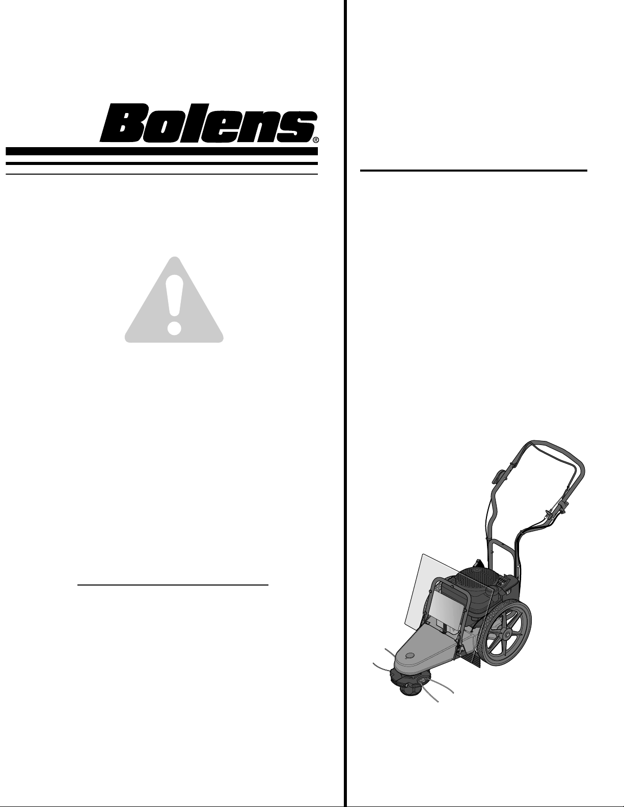
Model
52068 - 5HP Recoil Start
52069 - 6HP Electric Start
OWNER’S MANUAL
Trimmer/Mower
•
Safety
•
Assembly
•
Controls
•
Operation
•
Maintenance
•
Parts List
GARDEN WAY INCORPORATED
SAFETY FIRST!
Before operating this equipment, read this
Owner's Manual and the separate manual
supplied by the engine manufacturer.
(Electric Start Model Shown)
Page 2
Dear Owner:
You now own one of the finest trimmer/mowers available. It
was designed to easily handle a wide variety of trimming,
mowing and clearing chores. You will find the machine to
be an invaluable tool in caring for your property.
Please carefully read this Manual. It tells you how to safely
and easily assemble, operate and maintain your machine.
Be sure that you and any other operators carefully follow
the recommended safety practices at all times. Failure to
do so could result in personal injury or property damage.
Of course, if you should ever have any problems or questions, please contact your local authorized service dealer or
call the Factory (see back cover).
We want to be sure that you are completely satisfied at all
times.
The engine exhaust from this product contains
chemicals known to the State of California to cause
cancer, birth defects or other reproductive harm.
WARNING
See Back Cover for
Customer Service information
Safety Alert Symbol
This is a safety alert symbol. It is used in this
manual and on the unit to alert you to potential
hazards. When you see this symbol, read and
obey the message that follows it. Failure to obey
safety messages could result in personal injury or
property damage.
SECTION 1: SAFETY ...........................................1
General Operation ......................................................1
Slope Operation .........................................................2
Children......................................................................2
Service.......................................................................2
Safety Decals .............................................................3
SECTION 2: ASSEMBLY.......................................4
Inspection After Delivery............................................4
Step 1: Unpacking Unit ..............................................4
Step 2: Install Handlebars..........................................4
Step 3: Attach Throttle Control Lever.........................5
Step 4: Add Motor Oil.................................................5
Step 5: Check Trimmer Head Hardware .....................5
Step 6: Connect and Charge Battery...........................6
SECTION 3: FEATURES AND CONTROLS ...................7
SECTION 4: OPERATION ......................................8
Pre-Start Checklist.....................................................8
Fill Fuel Tank..............................................................8
Adjust Handlebar Height ............................................8
Adjust Line Cutting Height .........................................8
Use the Correct Diameter Trimmer Line.....................9
Using the Trimmer Head Control Bail.........................9
Operating the Trimmer/Mower...................................9
Additional Operating Tips and Techniques...............10
SECTION 5: MAINTENANCE.................................11
Required Maintenance Schedule..............................11
Adjusting Trimmer Head Engagement......................11
Removing and Replacing the Trimmer Head............12
Inspecting/Replacing the Drive Belt..........................12
Cleaning and Debris Removal ..................................14
Cleaning the Engine..................................................14
Lubrication...............................................................14
Compact Storage .....................................................14
General Engine Maintenance....................................14
Engine Oil Service....................................................14
Air Cleaner Service...................................................14
Spark Plug Service...................................................14
Spark Arrester Screen Service..................................14
Engine Cleaning .......................................................14
Carburetor/Governor Adjustments...........................14
Throttle Control Adjustment.....................................15
Off-Season Storage..................................................15
Battery Recharging/Replacement.............................15
Changing Trimming Lines........................................16
Troubleshooting.......................................................17
PARTS LIST ...................................................18
ACCESSORIES & KITS .......................................21
CUSTOMER SERVICE INFORMATION...........Back Cover
Table of Contents
Page 3
Safety
1
Section
1
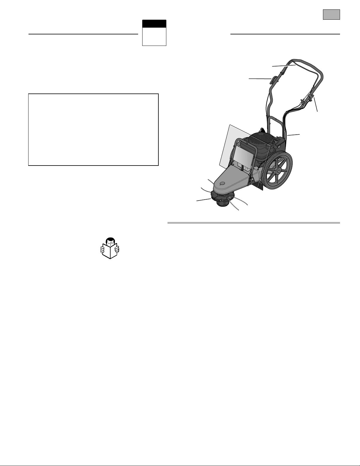
Figure 1-1 - Electric start model shown.
Trimmer Head Control Bail
Cutting Height
Settings
Engine Throttle Control Lever
Handlebar
Height Adjuster
Keyswitch
(Electric Start
Model)
GENERAL OPERATION
1. Read, understand, and
follow all instructions on the
machine and in the manuals. Be
thoroughly familiar with the controls and
the proper use of the equipment before
starting.
2. Do not put hands or feet near or
under rotating parts. Keep clear of the
rotating trimmer head and line at all
times.
3. Only allow responsible adults, who
are familiar with the instructions, to
operate the trimmer/mower. Never let
children or untrained adults operate this
equipment.
4. Inspect area where machine is to be
used. The machine can propel small
objects at high speed, causing personal
injury or property damage.Clear area of
objects such as rocks, toys, wire, bones,
sticks, etc., which could be picked up and
thrown by trimmer line.
5. Be sure the area is clear of other
people (particularly small children and
pets) before mowing. Stop machine if
anyone enters the area. Keep bystanders
at least 50 feet from the area of
operation.
6. Do not operate the machine when
barefoot or wearing open sandals. Always
wear substantial footwear.
7. Wear appropriate clothing such as a
long-sleeved shirt or jacket. Also wear
long trousers or slacks. Do not wear
shorts.
8. Do not wear loose clothing– it could
catch in the equipment.
9. Do not mow in reverse unless absolutely necessary. Always look down and
behind before and while moving backwards.
10. Do not operate the trimmer/mower
without proper guards, plates, or other
protective safety devices in place.
11. Refer to provided instructions for
proper operation and installation of
accessories. Only use factory-approved
accessories.
12. Stop trimmer head when crossing
gravel drives, walks, or roads. Wait for
trimmer lines to stop.
13. Stop engine and disconnect spark
plug wire from spark plug whenever you
leave the unit, clean the equipment, or
replace trimmer line. Remove key on electric start model.
14. Wait until the trimmer head comes to
a complete stop, shut the engine off, and
disconnect the spark plug wire before
installing or removing trimmer line. Be
sure trimmer head is securely attached
before operating equipment.
15. Mow only during daylight hours or
when good artificial light is available.
16. Do not operate the machine while
under the influence of alcohol or drugs,
or when tired or ill.
17. Never operate this equipment in wet
grass. Be sure of your footing; keep a firm
hold on the handlebar and walk; never
run.
18. Release the Trimmer Head Control
Bail before starting the engine.
19. If the unit starts to vibrate abnormally, stop the engine and disconnect the
spark plug wire. Check immediately for
the cause. Vibration is generally a
warning of trouble.
IMPORTANT
Safe Operation Practices for Walk-Behind
Mower
This cutting machine is capable of amputating
hands and feet and throwing objects. Failure
to observe the following safety instructions
could result in serious injury or death.
Page 4

2 Section 1: Safety
20. Always wear approved safety goggles or safety glasses with side shields
when operating equipment. The use of
any powered machine can result in foreign objects being thrown by high-speed
rotating parts which can cause personal
injury or property damage. Stay away
from glass and other easily thrown or
breakable objects.
21. Wear work gloves and sturdy
footwear when using this equipment.
Leather work shoes or short boots are
ideal. They protect ankles and shins from
rocks, pebbles, splinters, etc.
22. It is advisable to wear protective
headgear to prevent the possibility of
being hit by small flying particles, etc.
23. Before each use, inspect the Throttle
Control Lever and cable. Make sure the
cable is free and the lever functions
properly.
24. Watch for traffic when near or when
crossing roadways.
25. Never attempt to carry children or
other passengers on the equipment. They
could fall off and be seriously injured, or
they could interfere with safe operation of
the equipment.
26. The machine is equipped with a
plastic debris shield in front of the engine
and a rubber debris flap under the frame.
They must be in place and working properly. Never remove or cause the debris
shield or debris flap to cease working. If
either of these parts is missing or not
working properly, do not use the equipment until this situation is corrected.
27. Be aware of where the machine is
discharging materials and do not point
the discharge at anyone.
28. Never run the engine in an enclosed
area. Engine exhaust contains carbon
monoxide, a deadly gas that is odorless,
colorless and tasteless. Always run the
engine outdoors where there is adequate
ventilation.
29. Slow down before turning.
30. Shut off engine when not trimming
or mowing.
31. Use extra care when loading or
unloading machine into a trailer or truck.
32. Use this equipment for its intended
purpose only.
33. Always make sure the handlebars are
tight and comfortably positioned.
They should never be in an awkward
position for the operator.
SLOPE OPERATION
Slopes are a major factor related to loss
of control and tip-over accidents which
can result in severe injury or death. All
slopes require extra caution. If you can
not back up the slope or you feel uneasy
on a slope, do not mow it.
DO:
Mow across the face of slopes; never
up and down. Exercise extreme caution
when changing direction on slopes.
Avoid slopes greater than 15o.
Remove objects such as rocks, tree
limbs, etc.
Uneven terrain could overturn the
machine. Watch for holes, ruts, or
bumps. Tall grass can hide obstacles.
Use slow speed.
Use extra care with grass catchers or
other attachments. These can change
the stability of the machine. Keep all
movement on the slopes slow and
gradual.
Avoid starting or stopping on a slope.
DO NOT:
Do not mow near drop-offs, ditches, or
embankments. You could lose footing
or balance.
Do not mow on very steep slopes.
Do not mow on wet grass. Slippery
footing can be hazardous.
CHILDREN
Tragic accidents can occur if the operator
is not alert to the presence of children.
Children are often attracted to the
machine and the mowing activity. Never
assume that children will remain where
you last saw them.
1. Keep children out of the mowing area
and under the watchful care of a responsible adult.
2. Be alert and turn machine off if children
enter the area.
3. Before and while moving backwards,
look behind and down for small children.
4. Never allow children to operate the
machine.
5. Use extra care near blind corners,
shrubs, trees, or other objects that may
obscure vision.
6. Never carry children, even with the
trimmer head stopped. Children may fall
off and be seriously injured or interfere
with safe machine operation.
7. Do not allow children nearby if you
are working.
SERVICE
1. Use extra care in handling gasoline
and other fuels. They are flammable and
their vapors are explosive. To help prevent a fire or explosion:
a) Use only an approved container.
b) Never remove gas cap or add fuel
when the engine is running. Let
engine cool before refueling. Do not
smoke.
c) Never refuel the machine indoors.
Fill the fuel tank outdoors and with
extreme care.
d) Never store the machine or fuel
container inside where there is an
open flame, such as a water heater,
etc.
e) Replace caps on the fuel tank and
fuel container and clean up spilled
fuel before starting engine. Move
machine away from any gasoline
fumes before starting the engine.
f) Keep matches, smoking materials,
open flames, and sparks away from
the fuel tank and fuel container.
g) Leave 1/2" air space at the top of
the fuel tank to allow for fuel
expansion.
2. Never run the engine inside a closed
area.
3. Never clean, or make adjustments or
repairs with the engine running. Disconnect the spark plug wire and keep the
wire away from the plug to prevent accidental starting. Remove key on electric
start models.
4. Keep all nuts and bolts tight, especially the trimmer head attachment bolts,
and keep equipment in good condition.
Check mounting hardware on trimmer
head every time you change trimmer line
and prior to each use.
Page 5
Section 1: Safety 3
SAFETY DECALS
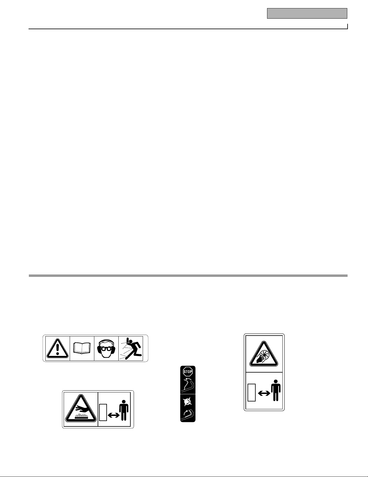
For your safety and the safety of others,
various safety and operational decals are
located on your unit (see below).
Keep the decals clean and legible at all
times. Contact your local service dealer or
the factory for replacements if any decals
are damaged or missing.
Refer to the Parts List in this manual for
decal locations, part numbers and
ordering instructions.
1903584 (12/94)
1903588 (12/94)
At front of deck
At front of deck
On right-side, rear of deck
On left
handlebar
5. Never tamper with safety devices.
Check their proper operation regularly.
6. To reduce fire hazard, keep mower
free of grass, leaves or other debris
build-up. Clean up oil or fuel spills. Let
machine cool before storing.
7. After striking an object, stop the
engine and disconnect the spark plug
wire. Inspect the machine and repair, if
necessary, before restarting.
8. Never make adjustments or repairs
while engine is running.
9. Components subject to wear,
damage and deterioration could expose
moving parts or allow objects to be
thrown. Frequently check components
and replace with factory recommended
parts, when necessary. Regularly inspect
the trimmer head and debris shield.
Make sure they are not bent, damaged, or
loose.
10. Only use eighteen-inch long .130" or
.155" diameter trimmer line. Never use
other lengths, diameters or material as
trimmer line.
11. Trimmer line moves at high speed
and can cut. Always stop the engine and
let all moving parts stop before replacing
the trimmer lines. Let the engine cool.
12. Do not change the engine governor
setting or overspeed the engine. The
governor controls maximum safe operating speed and protects the engine and
all moving parts from damage caused by
overspeed. Authorized service shall be
sought if a problem exists.
13. Do not touch engine parts which may
be hot from operation. Allow parts to
cool completely before inspecting,
cleaning or repairing the unit.
14. Maintain or replace safety and
instructional decals. Refer to the Parts
List for replacement decal information.
15. Use only original-equipment replacement parts. Parts manufactured by
others could present safety hazards and
affect performance even though they may
fit on this machine.
16. Remember – the end of the season is
a good time to inspect equipment prior to
storage.
17. To guard against engine overheating,
always keep the engine debris guard
mounted and clean.
18. For units equipped with electric start:
a) Batteries produce explosive gases.
Keep sparks, flame, cigarettes,
etc., away. Ventilate area when
charging battery. Do not charge
battery in an airtight space.
b) Do not use a battery charger other
than the one provided with the
unit.
c) The battery contains toxic mate-
rials. Do not damage the battery
case. If the case is broken or damaged, avoid contact with the battery contents.
d) Properly dispose of a damaged or
worn out battery. Check with local
authorities for proper disposal
methods.
e) Do not short circuit the battery.
Severe burns and fire can result.
1916424.A (12/98)
Page 6
Assembly
2
Section
4
INTRODUCTION
Carefully follow these assembly steps to
correctly prepare your machine for use.
It is recommended that you read this
Section in its entirety before beginning
assembly.
NOTE: If an assembly step applies only to
certain models, those models are noted
at the beginning of that step. Otherwise,
a step applies to all models.
INSPECTION AFTER DELIVERY
Inspect your machine immediately after it
has been delivered. Make sure that neither the carton nor the contents have
been damaged.
IMPORTANT: The engine is shipped
without motor oil in its crankcase. Motor
oil must be added to the engine before
starting.
NOTE: LEFT and RIGHT sides of unit are
as viewed from operator’s position
behind the handlebars.
ASSEMBLY
Tools/Supplies Needed:
• (1) Utility Knife or Scissors
• (2) 1/2" (or adjustable) Wrenches
• (2) 7/16" Wrenches (one with a boxed
end)
• Motor Oil (see Engine Owner’s Manual
for oil specifications and quantity
required)
STEP 1: UNPACKING UNIT
1. Remove the protective packaging
material (plastic film and cardboard) from
the handlebars and the unit.
2. Remove the handlebars from the insert
and carefully (do not pinch or kink the
attached cables) put them aside before
removing the unit from the shipping
carton.
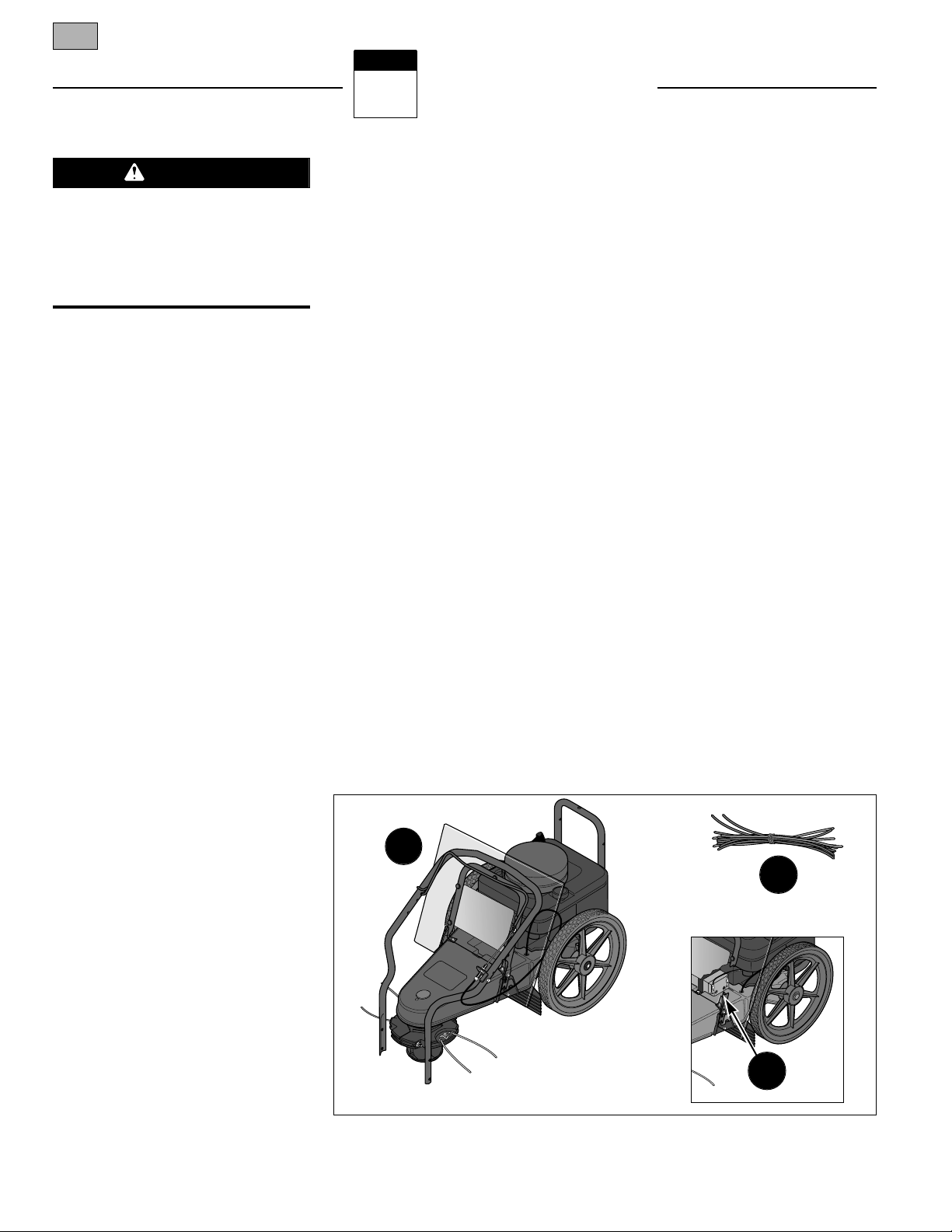
3. Compare the parts inside the carton
with the following list:
• Trimmer/Mower Assembly (A, Figure
2-1)
• Extra Trimmer Line (B, Figure 2-1): six
pieces of heavy-duty gauge .130" dia.
line and six pieces of extra-heavy-duty
gauge .155" dia. line.
• The following items are in a separate
package:
(3) Plastic cable ties
(1) Hex Hd. Screw, 1/4-20 x 2
(1) Hex Locknut, 1/4-20
(2) Hex Hd. Screw, 5/16-18 x 2
(2) Hex Locknut, 5/16-18
• Electric Start Model Only:
(1) Battery (installed on unit – see
C, Figure 2-1)
(2) Ignition Keys and (1) Battery
Recharger (in separate electric
start package)
STEP 2: INSTALL HANDLEBARS
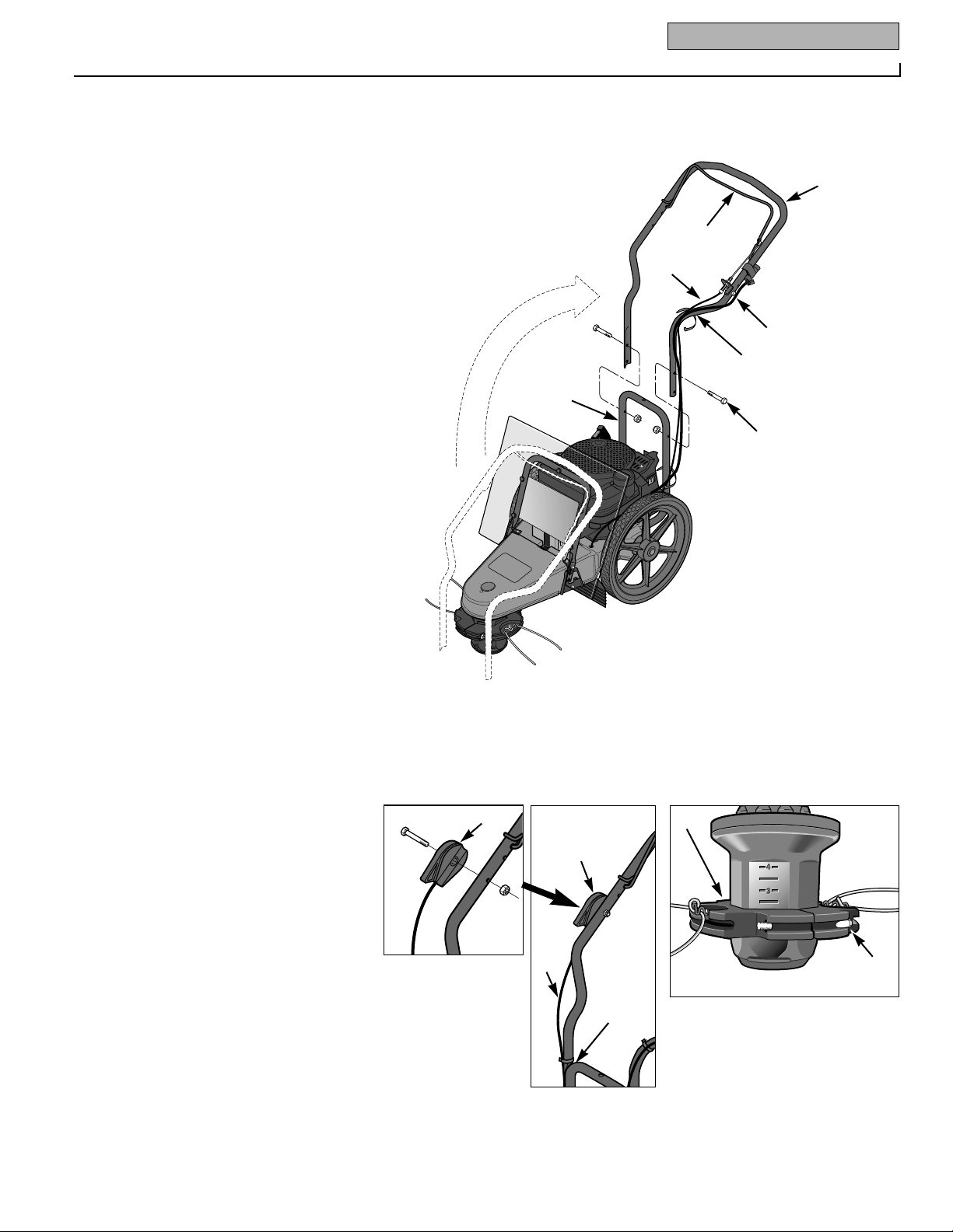
1. Cut the plastic tie and remove the tape
that secures the control bail (G, Figure
2-2) to the handlebar (A).
NOTE: Do not pinch or kink the attached
cable(s) while unfolding and securing the
handlebars.
2. Carefully lift the handlebars (A, Figure
2-2) to rear of the unit and align the handlebar legs with the handlebar support
bracket (B).
3. Route the trimmer head control cable
(C, Figure 2-2) to the outside of the handlebar. On electric start models, also
route the electrical wire harness (O) to the
outside of the handlebar.
4. Select the low or high height setting
holes in the handlebar legs and attach the
legs with the two 5/16-18 x 2 hex hd.
screws (D) and 5/16-18 locknuts (E)
from the hardware bag.
IMPORTANT: Adjust the handlebars as
close as possible to waist level so that
your arms are at a comfortable height.
This position will result in less pressure
on the mower wear cup, making the unit
easier to roll and reducing wear to the
wear cup.
A
Figure 2-1: Unit as shipped (recoil start model shown). Battery for electric start model is
shown in inset.
B
C
To prevent personal injury or property
damage, do not attempt to start the
engine until all assembly steps are
complete and you have read and understand all of the safety and the operating
instructions in this Manual.
WARNING
Page 7
Section 2: Assembly 5
5. Use two cable ties (F, Figure 2-2) to
secure the trimmer head control cable (C)
and the electrical wiring harness (O) to
the handlebar at the locations shown.
STEP 3: ATTACH
THROTTLE CONTROL LEVER
1. One end of the Throttle Control Cable
(H, Figure 2-3) is attached to the engine.
Gently unwind the cable from its shipping
position and position the Throttle Control
Lever (I) on the outside of the right handlebar, next to the throttle control decal.
2. Secure the Throttle Control Lever to
the handlebar with a 1/4-20 x 2 hex hd.
screw (J, Figure 2-3) and 1/4-20 hex
locknut (K).
3. Use a cable tie (L, Figure 2-3) to
secure the throttle cable (H) to the handlebar at the location shown.
STEP 4: ADD MOTOR OIL
1. The engine is shipped without motor
oil which MUST BE ADDED before the
engine is started.
2. See the separate Engine Owner’s
Manual for filling instructions and for the
correct oil specifications. Engine must be
level when checking oil level. In ambient
temperatures above 400 F, use a highquality, SAE 30 weight detergent oil classified for Service SF, SG or SH. Use no
special additives. Do not mix oil with fuel.
STEP 5: CHECK
TRIMMER HEAD HARDWARE
Check that the two bolts (M, Figure 2-4)
on the trimmer head are tightened
securely. The trimmer head can be
rotated to make access to the hardware
easier.
IMPORTANT: The trimmer head hardware
is designed to be permanently installed
and is not removable. Do not attempt to
replace it with non-factory specified hardware.
NOTE: The two holes (one is covered with
a plastic plug) on the top, front end of the
mower deck are access holes that allow
certain parts to be serviced.
Figure 2-2: Handlebar installation (electric start model shown).
A
C
D
E
B
G
F
O
M
M
Figure 2-4: Check trimmer head hardware for tightness.
Figure 2-3: Attach throttle lever to right-side
handlebar.
I
J
K
L
I
H
Page 8
6 Section 2: Assembly
STEP 6: CONNECT AND CHARGE
BATTERY (ELECTRIC START
MODELS)
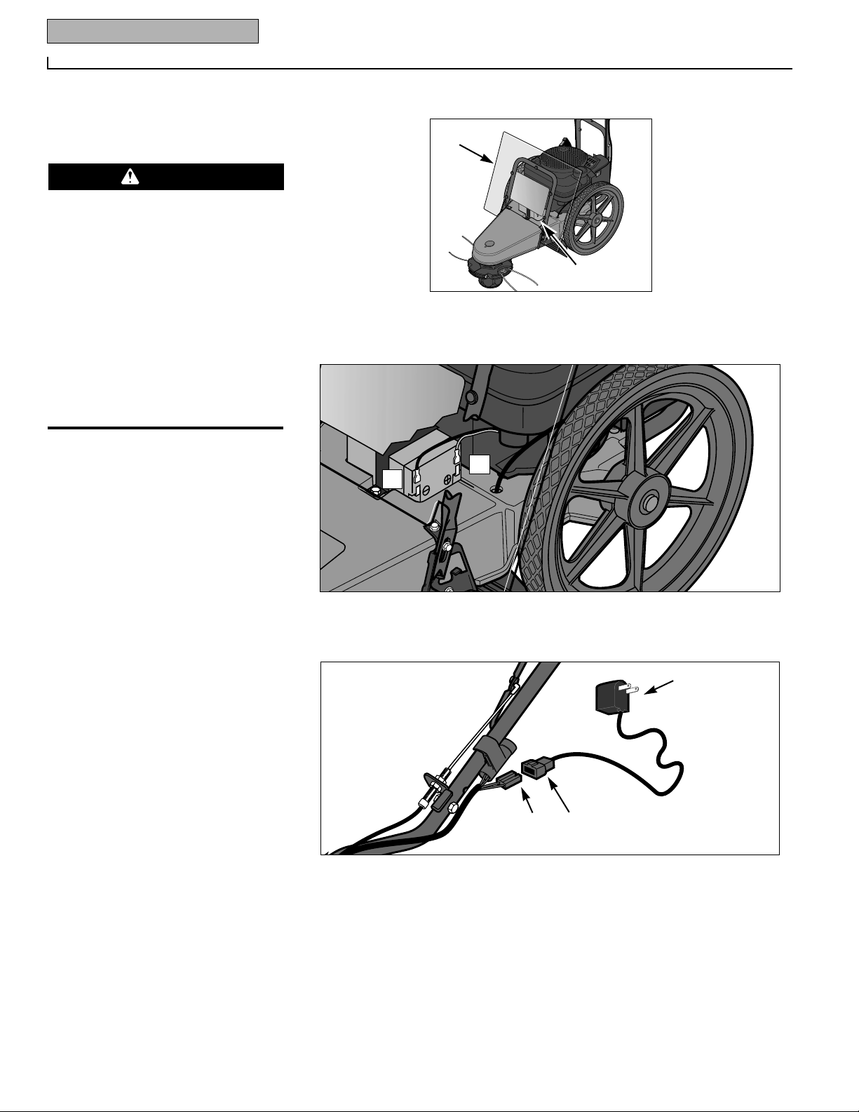
1. Lift and tilt debris shield (X, Figure 2-
5) forward to view battery (P). Connect
the red wire (R, Figure 2-6) to the positive
(+) red-coded terminal on the battery.
Then, connect the black wire (S) to the
negative (–) black-coded terminal on the
battery. Close the debris shield (X, Figure
2-5).
2. Connect the small plug (U, Figure 2-7)
on the battery recharger cord to the wire
harness plug (V) located near the
keyswitch. Then, plug the charger box
(W) into a grounded, 220V wall outlet.
3. Charge the battery for 24 hours. After
charging, first unplug the charger box (W)
from the wall outlet, then disconnect the
recharging line plugs (U and V).
• Wet conditions can cause an electric
shock hazard during battery
recharging. Avoid wet conditions when
charging battery.
• Recharging the battery with improper
equipment could cause a battery explosion. Use only the battery charger
shipped with the unit. The engine must
be shut off and the spark plug wire disconnected and moved away from the
spark plug.
Failure to comply could result in personal injury or property damage.
S
R
Figure 2-6
V
W
U
Figure 2-7
X
P
Figure 2-5: Lift and tilt debris shield
forward to access battery.
DANGER
Page 9
Features and Controls
3
Section
7
OPERATING SYMBOLS
Various symbols (shown here, with
word descriptions) are used on the
unit.
STOP
FEATURES AND CONTROLS
This Section describes the location and
function of the features and controls on
your machine. Refer to the following
Operation Section for detailed operating
instructions.
Do not start the engine until you read and
understand all safety, controls and operating instructions in this Manual, the separate Engine Owner’s Manual, and on the
decals on the machine.
IMPORTANT: Refer to the separate
Engine Owner’s Manual for detailed information about the controls on the engine.
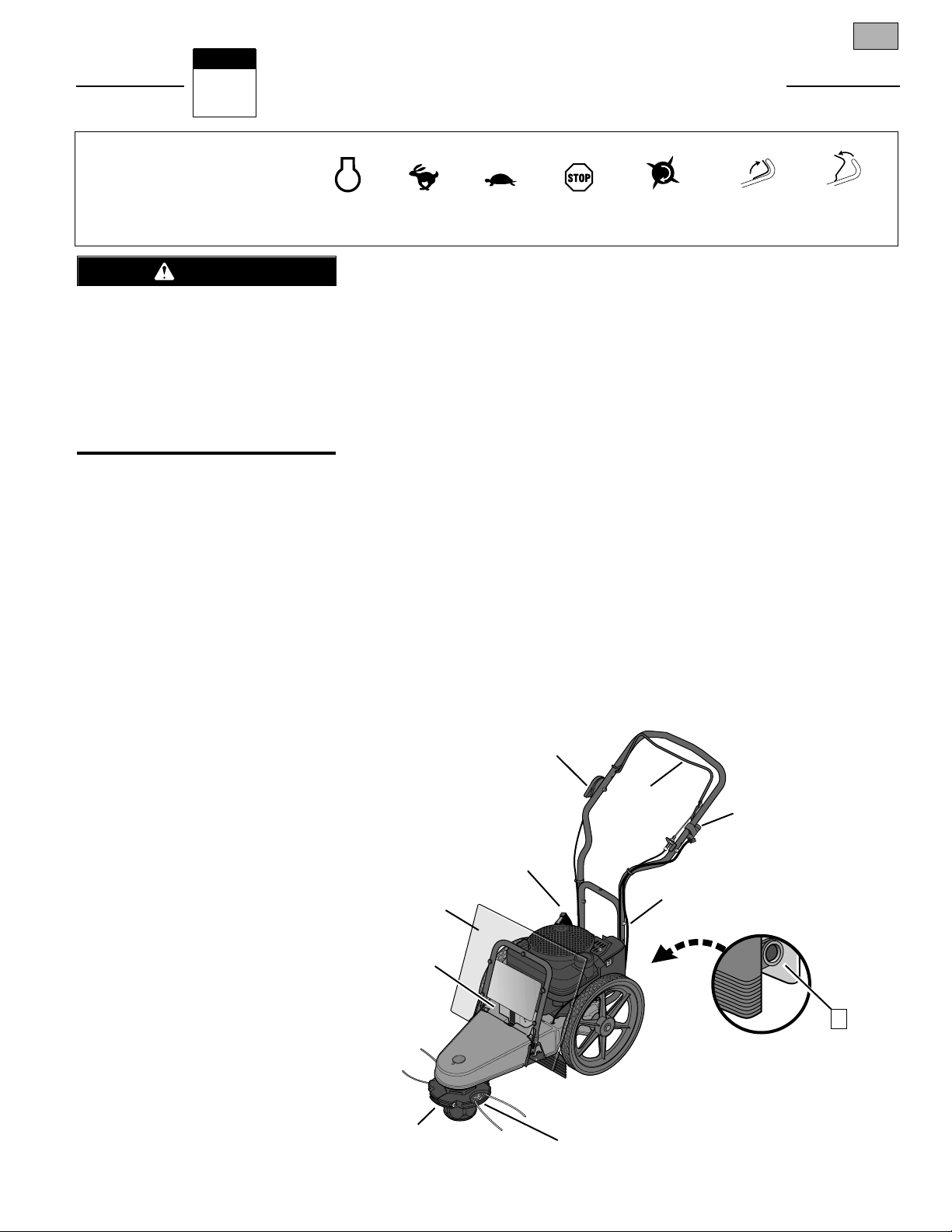
TRIMMER HEAD CONTROL BAIL
Pull the control bail (A, Figure 3-1) up
against the handlebar (engage bail) to
start rotation of the trimmer head. Let go
of the control bail (disengage bail) to
stop the trimmer head.
CUTTING HEIGHT SETTINGS
The trimmer head (B, Figure 3-1) is
adjustable to an infinite number of height
settings from 1-1/2" -to- 4-1/2".
TRIMMER LINE HOLDERS
The trimmer lines are secured to line
holders (C, Figure 3-1). Replacing the
trimmer lines is a simple procedure (see
Changing Trimming Lines in Section 5).
HANDLEBAR HEIGHT ADJUSTMENT
The handlebar (D, Figure 3-1) has two
height settings (see Adjust Handlebar
Height in the Operation Section).
PLASTIC DEBRIS SHIELD
The plastic debris shield (E, Figure 3-1)
protects the engine from all manner of
debris. The shield tilts forward for
access to the engine.
ENGINE THROTTLE CONTROL LEVER
Use this lever (F, Figure 3-1) to regulate
engine speed and to stop the engine. The
throttle settings are shown on the decal
next to the lever.
ENGINE RECOIL STARTER
The recoil starter (G, Figure 3-1) is
located at the rear of the engine and is
used to pull start the engine.
FUEL PRIMER BUTTON
The fuel primer button (I, Figure 3-2)
allows a cold engine to be primed for
faster, easier starting.
KEYSWITCH
(ELECTRIC START MODEL)
On electric start models, the keyswitch
(J, Figure 3-1) is used to start the engine.
The keyswitch does not have an engine
stop position. Use the Engine Throttle
Control Lever (F) to stop the engine.
IMPORTANT: Remove key from
keyswitch when leaving unit unattended
to help prevent unauthorized or unintentional starting.
BATTERY (ELECTRIC START MODEL)
On electric start models, the battery (K,
Figure 3-1) will crank the engine starter
motor when the keyswitch is turned to
the start position. Do not crank engine
longer than five (5) seconds per each
starting attempt.
ENGINE
STOP
TRIMMER
HEAD
ENGAGE
BAIL
DISENGAGE
BAIL
SLOW
FAST
STOP
Figure 3-1: Features and controls (electric start model shown).
J
C
B
G
K
F
A
E
I
D
Before operating your machine, carefully read and understand all safety,
controls and operating instructions in
this Manual, the separate Engine
Owner’s Manual, and on the decals on
the machine.
Failure to follow these instructions can
result in serious personal injury.
WARNING
Page 10
Operation
4
Section
8
INTRODUCTION
Read this Section thoroughly before you
start the engine. As with any piece of
outdoor power equipment, getting the
“feel” for how your machine operates and
knowing the best techniques for particular jobs are important to overall good
performance.
NOTE: All references to LEFT, RIGHT,
FRONT and REAR of the machine are
determined by standing in the operator’s
position.
PRE-START CHECKLIST
1. Review Section 1: Safety and also
Section 3: Features and Controls.
2. Check for loose or missing hardware.
Tighten or replace as needed.
3. Check the engine oil level*. It must
be up to the “FULL” mark on the oil dipstick. (See the Engine Owner’s Manual
for instructions.)
4. Check the fuel level* in the fuel tank.
(See the Engine Owner’s Manual and this
page for instructions.)
5. Check the Trimmer Head Control Bail
and the Engine Throttle Control Lever for
freedom of movement.
6. Select the cutting height (see Adjust
Line Cutting Height in this Section).
7. Check handlebar height position.
8. On electric start models, check the
wire harness connections.
9. Carefully check the area to be trimmed
and remove any debris.
10. Install the correct diameter trimmer
line (see Use the Correct Diameter
Trimmer Line in this Section).
11. Check that the spark plug wire is
securely attached to the spark plug.
* Clean debris from around fuel cap,
oil dipstick and engine (see “Cleaning
Debris” in Engine Owner’s Manual)
before checking oil level or adding
gasoline.
FILL FUEL TANK
1. Lift and tilt plastic debris shield
(E, Figure 3-1) forward.
2. Clean fuel fill area and engine (see
“Cleaning Debris” in Engine Owner’s
Manual) each time before fuel is added.
3. Fill the fuel tank with gasoline
according to the directions in the separate Engine Owner’s Manual. Follow all
instructions and safety rules carefully.
4. Securely replace the fuel tank cap and
the fuel container cap. Promptly wipe up
any fuel spills.
5. Lift and tilt the debris shield back,
then push it down to secure it.
ADJUST HANDLEBAR HEIGHT
To adjust handlebar height, refer to Install
Handlebars in the Assembly Section of this
Manual.
ADJUST LINE CUTTING HEIGHT
The cutting height of the trimmer line
adjusts from 1-1/2"-to-4-1/2" high in infinite increments. The cutting height has
been factory-set at one of the higher settings – we recommend that you start at
this higher setting and make adjustments
as needed.
In general, use higher height settings to
handle taller material and to cope with
tougher cutting conditions. For less
demanding situations, use any trimming
height desired. To adjust the cutting
height:
1. The cutting line height can be changed
when the wear cup is in contact with the
ground. If necessary, you may tip the
unit back slightly for a better view (do not
tip unit all the way back or motor oil may
flow to the exhaust area and the engine
may smoke for several seconds when
started).
2. Use a 1/2" wrench to loosen both
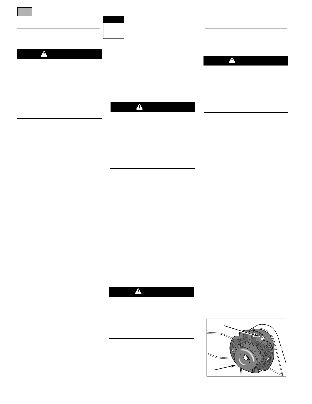
bolts (A, Figure 4-1) securing the trimmer
head.
3. The cutting heights are marked on the
side of the spindle head (Figure 4-2).
Move the top of the trimmer head to the
desired setting.
4. Tighten both trimmer head bolts
securely (to 75 in/lbs.) and evenly.
Before adjusting handlebar height, stop
engine and wait for all moving parts to
stop, disconnect spark plug wire and
prevent it from touching spark plug.
Failure to comply could result in personal injury or property damage.
Before adjusting the cutting height, shut
off the engine, wait for all moving parts
to stop, allow the engine to cool, disconnect the spark plug wire and prevent
it from touching the spark plug.
Failure to comply could result in personal injury or property damage.
GASOLINE IS HIGHLY FLAMMABLE AND
ITS VAPORS ARE EXPLOSIVE.
Follow gasoline safety rules in this
Manual (see Section 1) and in the separate Engine Owner’s Manual.
Failure to follow gasoline safety rules
and instructions can result in serious
personal injury and property damage.
Before operating your machine, carefully read and understand all safety
(Section 1), controls (Section 3) and
operating instructions (Section 4) in this
Manual, in the separate Engine Owner’s
Manual, and on the decals on the
machine.
Failure to follow these instructions can
result in serious personal injury.
WARNING
Figure 4-1
A
A
DANGER
CAUTION
CAUTION
Page 11
Section 4: Operation 9
USE THE CORRECT
DIAMETER TRIMMER LINE
Before starting a project, examine the
grass or material you will be cutting and
trimming.
For tougher conditions, use two (or four)
sections of the thicker gauge, .155" diameter extra-heavy duty line. For less
demanding conditions, use two sections
of the thinner gauge, .130" diameter
heavy-duty line. The thicker line has the
heft to chop through tougher materials,
while the thinner line provides a more
precise cut. To change trimmer lines,
refer to Changing Trimmer Lines in
Section 5.
NOTE: The thinner gauge line is also recommended for use near trees or ornamentals to help prevent girdling (cutting
the bark).
USING THE TRIMMER
HEAD CONTROL BAIL
Before starting the engine, it is essential
to know how to use the Trimmer Head
Control Bail.
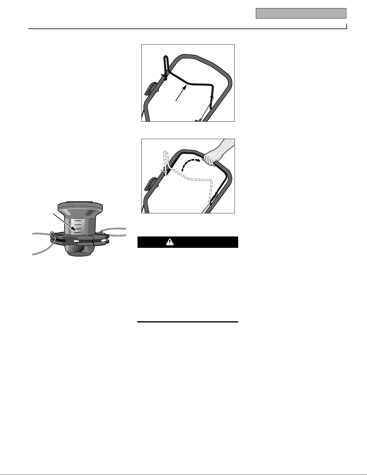
1. The Trimmer Head Control Bail (A,
Figure 4-3) is used to start and stop
trimmer head motion.
2. Leave the control bail in the disengaged (released) position when starting
the engine to prevent the trimmer head
from turning when the engine starts. See
Figure 4-3.
3. When the engine is running, pull up
and hold the control bail against the handlebar (Figure 4-4) to start rotation of the
trimmer head.
4. Let go of the control bail to stop the
trimmer head. The control bail should
spring forward to the disengaged position. If it doesn’t, do not use the machine
until the control bail has been repaired.
OPERATING THE
TRIMMER/MOWER
Once you have read and understood the
sections in this Manual on Safety,
Assembly, Features and Controls, and
Operation, you are ready to start and
operate your trimmer/mower.
CHECKLIST BEFORE STARTING
1. Complete the Pre-Start Checklist in
this Section of the Manual. You must
wear safety glasses or goggles.
2. Check that the line cutting height is
adjusted according to the instructions.
STARTING THE ENGINE
1. Move the unit to the work area.
2. Connect the spark plug wire to the
spark plug.
3. Put on safety-approved eye
protection.
4. Release (disengage) the Trimmer
Head Control Bail (A, Figure 4-3).
5. Put the Engine Throttle Control Lever
in the FAST (rabbit symbol) position.
6. Push in the fuel primer button as
instructed in the Engine Owner’s Manual.
NOTE: Do not use primer to restart a
warm engine after a short shutdown.
7. Recoil Starting: Pull recoil start rope
slowly until resistance is felt. Then pull
rope out rapidly to start engine. Let rope
back in slowly. NOTE: If engine fails to
start after three pulls, repeat step 6.
Electric Starting: Stand behind handlebars and turn ignition key clockwise to
crank engine. If engine does not start
after five seconds of cranking, stop and
repeat step 6. When engine starts,
release key.
TO START THE TRIMMER HEAD
1. Stand in the operator’s position
directly behind the handlebars.
2. Slowly close the Trimmer Head Control Bail (Figure 4-4) against the handlebars to activate the trimmer head. Use
the Engine Throttle Lever to adjust the
turning speed of the trimmer head.
3. Once the trimmer head is revolving,
push the trimmer/mower along the path
to be cut.
TO STOP THE TRIMMER HEAD
Let go of the Trimmer Head Control Bail.
It will return to its open position and the
trimmer head will stop turning.
TO STOP THE ENGINE
Put the Engine Throttle Control Lever in
the STOP position. (If time allows, first
move throttle lever to SLOW setting
before stopping engine.)
Figure 4-2
Height
Guide
Figure 4-3: Control bail disengaged.
A
Figure 4-4: Control bail engaged.
If the trimmer head control bail is not
operating properly, shut off the engine,
disconnect the spark plug wire and move
wire away from plug.
Adjust or repair the control bail before
using the trimmer/mower.
Failure to follow this instruction could
result in personal injury or property
damage.
WARNING
Page 12

10 Section 4: Operation
ADDITIONAL OPERATING TIPS
AND TECHNIQUES
TIPS FOR PRECISION CUTTING
For the most precise cutting possible, be
sure to select the appropriate line cutting
height and trimmer line size (thickness)
for the conditions at hand.
When mowing, let the cutting head rest
lightly on the ground and do not lift up on
the handlebars. This allows the cutting
head to follow the ground contour
closely, resulting in the most even cut
possible. Also, be sure to ease into
heavy growth to prevent overwhelming
the machine.
TRIM WHEN WET OR DRY
Grass and most other materials are most
efficiently trimmed when dry. But, the
trimmer/mower will do a fine job even
with damp or wet materials. When conditions are moist or damp, be sure to
clean debris off the machine regularly to
keep cutting efficiency high. And watch
your footing!
CLEAN THE TRIMMER/MOWER
ON A REGULAR BASIS
Clean under the mower deck frequently to
remove any grass buildup. Also clean
around the muffler and on top of engine.
See the cleaning instructions in Section
5: Maintenance and in the separate
Engine Owner’s Manual.
DO NOT LET THE TRIMMER
LINES BECOME TOO SHORT
Once the trimmer lines are worn to less
than 1/2 their original length, trimming
jobs begin to take far longer than they
should.
As a general guideline, once the line
length becomes half of its original length,
it’s time to change to new lines.
USE EXTREME CAUTION ON SLOPES
When operating on sloping ground, use
extreme caution and common sense to
avoid possible injury or property damage.
Do not mow on excessively steep slopes!
Avoid slopes if greater than 150or wherever footing is unsure. If a slope is difficult to stand on, it is probably too steep
to trim or mow. In this case, it may be
wiser to establish a permanent ground
cover on this area.
Do not trim on slopes when the ground is
slippery. Trim across the face of a slope,
not up and down. Slow down and exercise caution when changing direction on
slopes.
USE CORRECT WALKING SPEED
Use a walking speed that is suitable for
the conditions at hand. For example,
you’ll get better trimming and mowing
results at slower walking speeds if the
grass is tall or lush. Shorter grass or
less dense growth can be cut at faster
travel speeds.
VARY THE THROTTLE SETTING
ACCORDING TO CONDITIONS
The majority of trimming and mowing
jobs will yield the best results if the
Engine Throttle Control is set at the
fastest engine speed.
Less demanding jobs that require very
precise cutting will yield better results if
the engine throttle is backed off somewhat to reduce engine speed. (For
example, damage to trees and ornamentals can be avoided by reducing the
engine speed; using the lighter .130"
diameter line; and by keeping a safe distance away.)
Again, once you begin a particular job
and get a “feel” for the conditions, you
will be able to make adjustments for the
best possible results.
KEEP THE MOWED SIDE TO YOUR
RIGHT AS YOU MOVE AHEAD
The trimmer/mower feeds cut materials
to the right side. Stay on the right side of
unmowed growth as you move along.
THROWN OBJECT HAZARD
• Objects such as rocks, pebbles,
and small debris will be thrown
violently by the cutting head,
resulting in significant hazard to
eyes and exposed body parts.
• Always wear safety-approved eye
protection and suitable clothing
and footwear.
• Keep children, pets and bystanders
50 feet away from machine while
operating.
• Be alert to hidden obstacles.
Failure to comply could result in
injury or property damage.
WARNING
NOTE: If the trimmer is operated in a
stationary position with the wear cup in
contact with dry vegetation, significant
heat will result that may deform the
plastic spindle or scorch vegetation.
Page 13
Maintenance
5
Section
11
ADJUSTING TRIMMER
HEAD ENGAGEMENT
The tension on the drive belt must be
correct for proper operation of the
trimmer head. If the tension is correct,
the trimmer head will rotate when the
Trimmer Head Control Bail is pulled back
against the handlebar (another indication
of correct tension is if the engine stalls
when the trimmer head becomes bound
up in very tough material.)
A worn or loose drive belt will slip on its
pulleys, causing the trimmer head to
move slowly, or not at all, when the control bail is engaged (belt squealing may
also be noticeable).
If the tension is too tight, the trimmer
head may rotate before the control bail is
engaged, or when there is no free play in
the control bail.
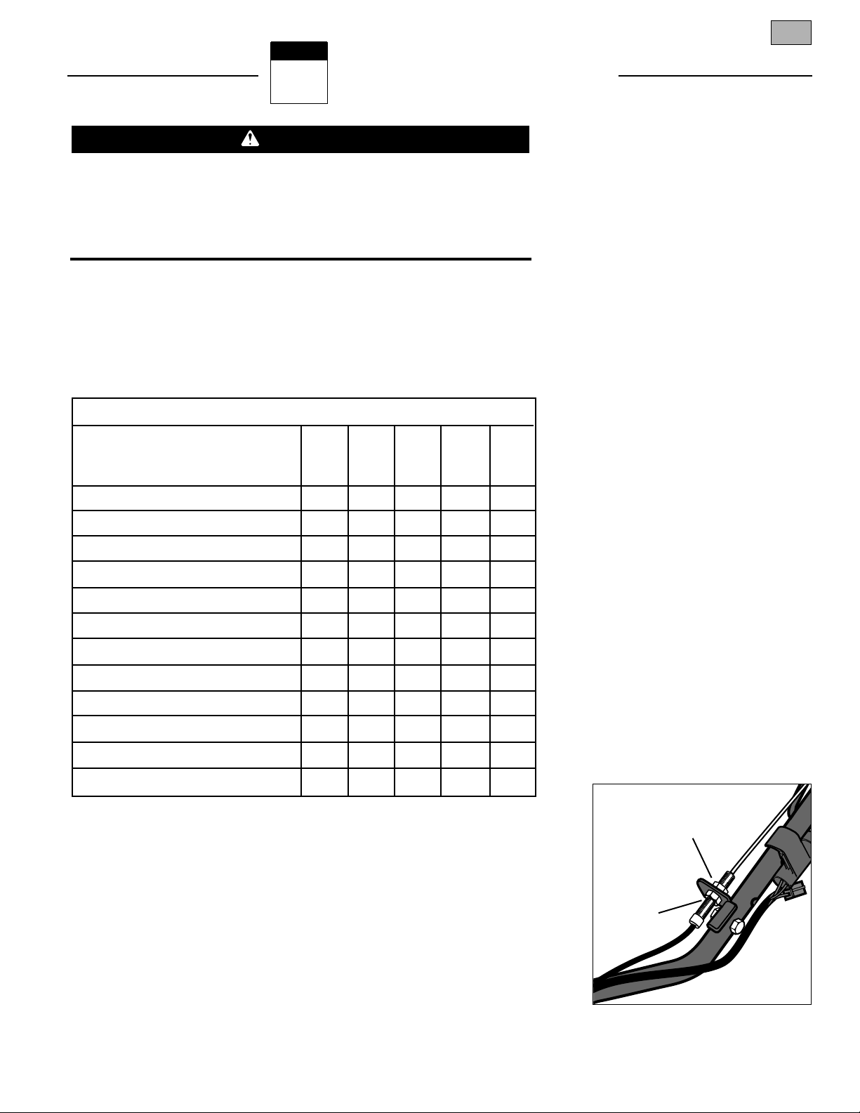
TO ADJUST BELT TENSION
1. Stop the engine and wait for all parts
to stop moving. Adjust the position of
the two nuts on the control cable adjustment stud (see Figure 5-2) as described
next:
a. To tighten belt tension, move the
upper nut (A, Figure 5-2) upward, then
move the lower nut (B) upward.
Tighten both nuts securely.
b. To loosen belt tension, move the
lower nut (B, Figure 5-2) down and
then the upper nut (A) down. Tighten
both nuts securely.
REQUIRED MAINTENANCE SCHEDULE
BEFORE EVERY EVERY EVERY AS
REQUIRED MAINTENANCE EACH 5 25 100 NOTED
USE HOURS HOURS HOURS
CHECK ENGINE OIL LEVEL ••
CHECK TRIMMER/MOWER LINES • 1
CHECK TRIMMER HEAD ENGAGEMENT •
ENGINE/MACHINE CLEANING • 3
CHECK NUTS AND BOLTS •
CHANGE ENGINE OIL • 2, 5
SERVICE AIR FILTER SYSTEM • 5
CLEAN UNDER DECK •
GENERAL LUBRICATION •
INSPECT DRIVE BELT •
CLEAN ENGINE • 4
CHECK WEAR CUP • 6
NOTE 1 – New line replacement is suggested when old line is 50% or less of original length.
NOTE 2 – Change oil after first two hours of new operation; thereafter every 25 hours.
NOTE 3 – Clean daily if used in extremely dusty/dirty conditions (see Engine Owner’s Manual).
NOTE 4 – Clean before using machine and at each fuel refill.
NOTE 5 – Service more often if used in extremely dusty or dirty conditions (see Engine
Owner’s Manual).
NOTE 6 – Replace when severe gouges exist on bottom surface.
Chart 5-1
Before inspecting, cleaning or servicing the machine, shut off engine, disconnect spark plug wire, and make sure that all moving parts have come to a complete stop. Remove ignition key on electric start models.
Failure to follow these instructions can result in personal injury or property
damage.
WARNING
NOTE: LEFT and RIGHT sides of unit are as viewed
from operator’s position behind the handlebars.
Figure 5-2: Belt tension adjustment.
B
A
Page 14
12 Section 5: Maintenance
Before inspecting, cleaning or servicing the machine, shut off engine, wait for all moving parts to
come to a complete stop, disconnect spark plug wire and move wire away from spark plug.
Failure to follow these instructions can result in serious personal injury or property damage.
REMOVING AND REPLACING
THE TRIMMER HEAD
1. Stop the engine and wait for all
moving parts to stop. Disconnect spark
plug wire and move it away from the
spark plug. Remove the ignition key on
electric start models.
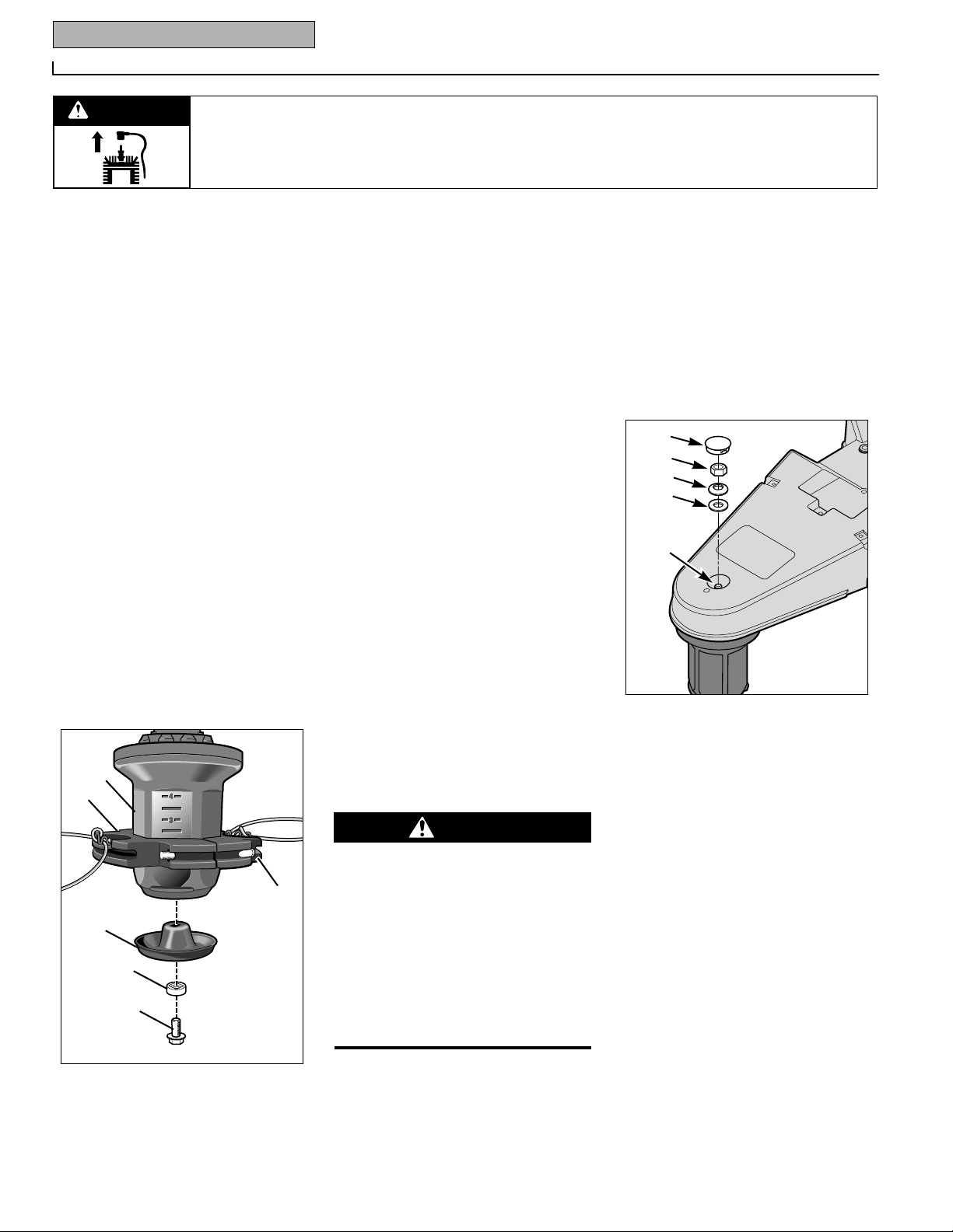
2. Two bolts (A, Figure 5-3) secure the
trimmer head (B) to the spindle head (C).
Loosen both bolts (not the nuts) just
enough to open up the trimmer head and
allow it to slide down the spindle head
and past the two stops. Do not attempt
to remove the bolts completely – they are
permanently attached.
3. Install the new trimmer head on the
spindle head. Tighten the hardware
securely (to 75 in/lbs.) and evenly.
4. If the wear cup (D, Figure 5-3) is
worn, replace it. Use a 1/2" socket
wrench to remove the screw (E, Figure 5-
3) and washer (F). Install the new wear
cup and reinstall the washer and screw.
Tighten the screw securely.
INSPECTING / REPLACING
THE DRIVE BELT
The drive belt can be inspected or
replaced from beneath the machine deck.
The belt should not require inspection for
many hours of operation. If replacement
becomes necessary, follow the instructions given here.
BELT INSPECTION
Stop the engine and let all moving parts
stop. Allow the engine to cool. Disconnect the spark plug wire and move it
away from the spark plug. Remove the
ignition key on electric start models.
1. For convenience, we recommend that
you place the unit on a raised platform to
make access to the underside of the deck
as easy as possible.
2. Examine the belt. Feed it around the
rear (engine) pulley so the entire belt can
be examined. If cracks or other damage
are noted, a new belt is needed.
BELT REMOVAL
1. Stop the engine and wait for engine to
cool. Disconnect the spark plug wire and
move it away from the spark plug.
Remove the ignition key on electric start
models.
2. Remove gasoline from fuel tank.
3. Carefully tip unit on its left side and
secure it in place.
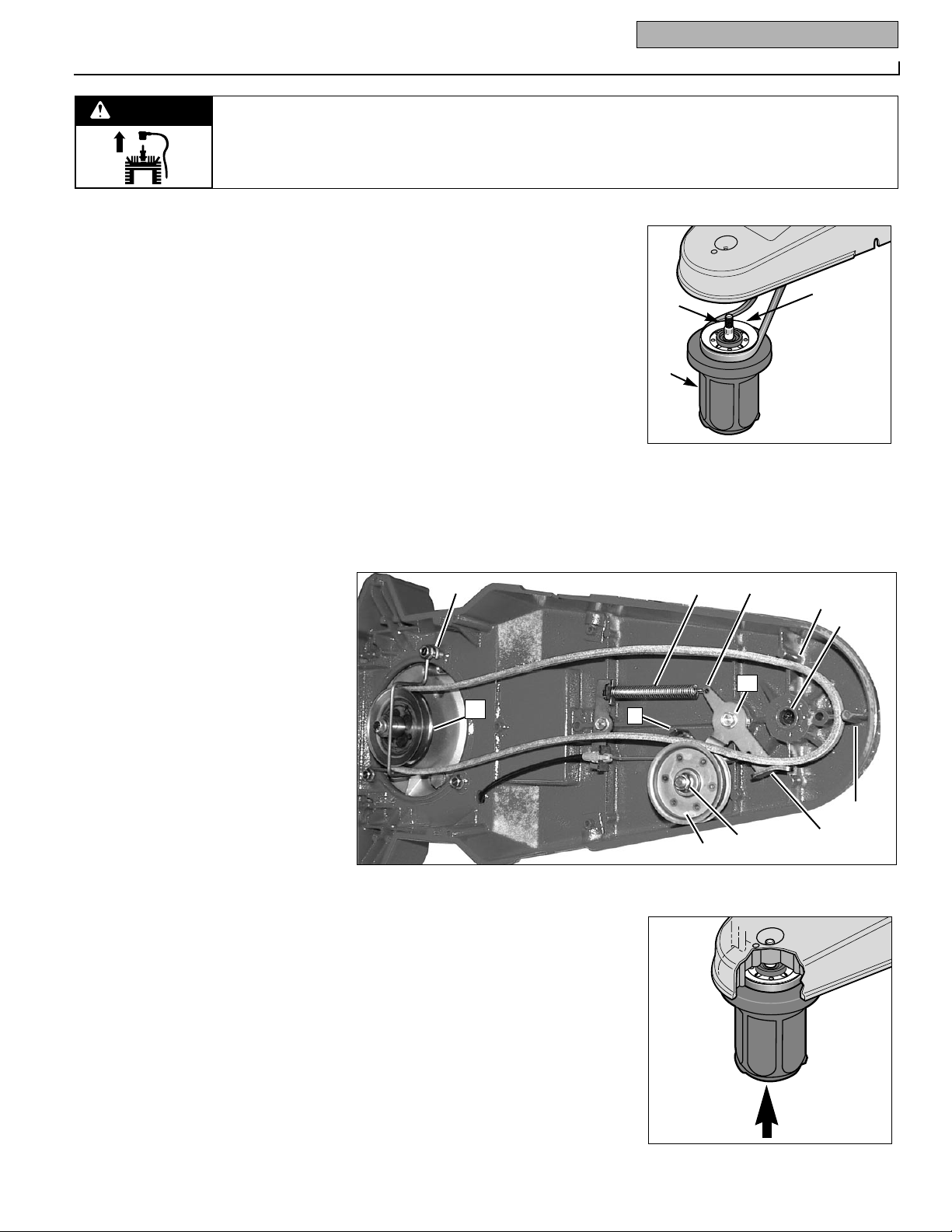
4. Remove the plastic plug (A, Figure 5-
4) from the top of the mower deck.
5. Using a 3/4" socket wrench, remove
nut (B, Figure 5-4), Belleville washer (C)
and flat washer (D) from spindle shaft
(E).
6. Thread nut (B, Figure 5-4) a few turns
back onto spindle shaft (E) to protect
threads on spindle shaft during the next
step.
7. Loosen the spindle shaft by placing a
wood block against the top of the nut (B,
Figure 5-4) and firmly striking the wood
block with a hammer.
8. Remove the nut from the spindle shaft
and then remove the spindle shaft (E,
Figure 5-5) and entire spindle head
assembly (F) from the bottom of the
deck. Slip the belt off the spindle head
pulley (P).
9. Disconnect the idler arm spring (R,
Figure 5-6) from the hole in the idler arm
(T).
10. Using a 1/2" wrench, loosen the idler
arm mounting screw (S, Figure 5-6) two
full turns.
Figure 5-3
GASOLINE IS HIGHLY FLAMMABLE AND
ITS VAPORS ARE EXPLOSIVE.
• Drain fuel into approved container outdoors, away from open flame.
• Be sure engine and muffler are cool
before draining gasoline.
• Do not smoke.
Failure to comply can result in serious
personal injury and property damage.
DANGER
Figure 5-4
A
B
C
D
E
A
B
D
F
E
C
WARNING
Page 15
Section 5: Maintenance 13
Before inspecting, cleaning or servicing the machine, shut off engine, wait for all moving parts to
come to a complete stop, disconnect spark plug wire and move wire away from spark plug.
Failure to follow these instructions can result in serious personal injury or property damage.
11. Using a 9/16" wrench and a 7/32" hex
(Allen) wrench, loosen the mounting nut
(G, Figure 5-6) and screw on the idler
pulley (I) a few turns, or until belt is free
to slip out between pulley and belt guide
(J). Remove belt.
12. Loosen rear belt guide screw (K,
Figure 5-6) enough to allow belt to be
removed from engine pulley (L). Remove
belt from unit.
BELT REPLACEMENT
1. Install belt on engine pulley (L, Figure
5-6) and retighten rear belt guide screw
(K) securely.
2. Route belt between idler pulley (I,
Figure 5-6) and belt guide (J), to inside of
brake arm (M), and next to die-cast belt
guides (N).
3. Securely tighten the mounting nut (G,
Figure 5-6) and screw in the idler pulley
(I).
4. Securely tighten the idler arm
mounting screw (S, Figure 5-6). After
tightening, check that idler arm is free to
rotate. If not, remove idler arm and check
for debris that may be interfering with
freedom of movement.
5. Look at the spindle head mounting
hole (O, Figure 5-6) and note the grooves
that are cut into the inner sides of the
hole. These grooves were formed by the
splines on the spindle shaft (E, Figure
5-5).
6. Install the belt on the spindle head
pulley (P, Figure 5-5) and insert the
spindle shaft (E) (with attached spindle
head assembly) into the spindle head
mounting hole (O, Figure 5-6). Rotate the
spindle head assembly to align the
splines on the spindle shaft with the
grooves in the mounting hole. Check
that the belt is still in the pulley groove
and is to the inside of the die-cast belt
guides (N, Figure 5-6).
7. Using a firm push on the spindle head
assembly (Figure 5-6A), seat the spindle
head assembly into the hole. Check that
the threaded end of the spindle shaft is
protruding through the bottom of the
hole.
8. Reinstall the flat washer (D, Figure 5-
4), Belleville washer (C) and nut (B) on
the spindle shaft. Note that the dished-in
side of the Belleville washer must face
the flat washer. Tighten the nut securely
(torque to 50 ft./lbs.), while checking frequently to ensure that the spindle head
rotates freely. If the spindle head binds,
it could be due to the belt being pinched
between the spindle head and the belt
guides. If so, remove the spindle head
assembly and repeat steps 5-7.
9. Replace plastic plug (A, Figure 5-4).
10. Reattach the idler arm spring (R,
Figure 5-6) in the hole in the idler arm
(T).
11. A new belt may need to be adjusted
by following the Adjusting Trimmer Head
Engagement instructions in this Section.
Figure 5-5
Figure 5-6
E
F
P
R
T
K
N
N
O
M
G
I
S
J
L
Figure 5-6A
WARNING
Page 16
14 Section 5: Maintenance
Before inspecting, cleaning or servicing the machine, shut off engine, wait for all moving parts to
come to a complete stop, disconnect spark plug wire and move wire away from spark plug.
Failure to follow these instructions can result in serious personal injury or property damage.
TRIMMER/MOWER CLEANING
AND DEBRIS REMOVAL
Thorough and regular cleaning of debris
from the engine and the machine is
required for maximum engine efficiency
and good overall performance. Inspect
and clean the following areas regularly,
making sure the engine is stopped, and
cool, before proceeding:
• Brush and wipe off all engine surfaces,
especially before checking oil or
adding fuel. Do not let debris, oil or
grease accumulate. To access the
front of the engine, lift the debris shield
up and tilt it forward.
• Wipe the deck clean, particularly near
the engine muffler.
• Clean the underside of the deck.
• Keep safety and operating decals clean
and legible.
• Keep all operating control levers
debris-free so they work properly.
CLEANING THE ENGINE
Before each use of the machine and at
each refueling, clean grass, chaff or
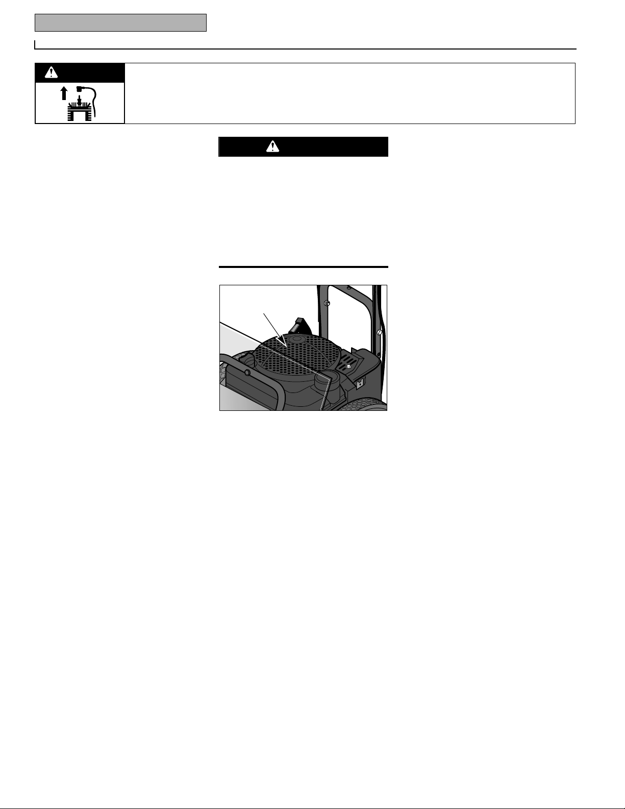
accumulated debris from the finger
guard area on top of the engine (see
Figure 5-7), and from the linkage,
springs and controls on the engine.
Keep the area around and behind the
muffler free of any combustible debris.
See “Cleaning Debris” in the Engine
Owner’s Manual for complete cleaning
instructions. Do not use water to clean
engine parts as water could contaminate
the fuel system. Use a brush or dry
cloth. Be sure engine is cool before
cleaning around muffler area.
NOTE: The separate engine air cleaner
must also be serviced according to the
instructions in the Engine Owner’s
Manual.
LUBRICATION
Applying light oil or a silicone-based
lubricant to your machine allows the following parts to work smoothly and protects them from the elements:
• Throttle control cable
• Control bail cable
• Nuts, bolts and other hardware
NOTE: The spindle head is permanently
lubricated at the factory. There is no
need for additional lubrication.
COMPACT STORAGE
For compact storage, remove the two
screws and locknuts securing the handlebar and carefully (to avoid kinking the
cables) rotate the handlebar so that the
upper portion rests on the engine and
the handlebar legs face to the rear.
GENERAL ENGINE
MAINTENANCE
Perform the following engine maintenance according to the engine maintenance schedule and instructions in the
separate Engine Owner’s Manual:
Engine Oil – Check the engine oil level
before starting the engine each day and
check it after each 5 hours of continuous
operation. Running the engine when it is
low on oil will quickly ruin the engine.
Change the oil after every 25 hours of
operation and even sooner when operating in extremely dirty or dusty conditions.
Air Cleaner – The air cleaner filters dirt
and dust out of the air before it enters the
carburetor. Operating the engine with a
dirty, clogged air filter can cause poor
performance and damage to the engine.
Never operate the unit without the air
cleaner installed. Inspect and service the
air cleaner after every 25 operating hours,
more often if operating in very dusty or
dirty conditions. See the Engine Owner’s
Manual for cleaning or replacement
instructions.
Spark Plug – Inspect and clean or
replace the spark plug after every 100
operating hours or annually. Refer to
the Engine Owner’s Manual for cleaning
or replacement instructions.
Spark Arrester Screen – If the engine is
equipped with a spark arrester screen,
remove and clean it according to the
time intervals and instructions in the
Engine Owner’s Manual.
Engine Cleaning – The engine must be
clean to assure smooth operation and to
reduce the risk of overheating and ignition of accumulated debris. Refer to the
Engine Owner’s Manual for specific
cleaning instructions.
Carburetor/Governor Control
Adjustments – The carburetor was
adjusted at the factory for best operating
speed. See the Engine Owner’s Manual
for any adjustment information.
The governor controls the maximum
safe operating speed and protects the
engine and other moving parts from
damage caused by overspeeding. Do not
tamper with the governor settings. Seek
authorized service if you think an adjustment is required.
Figure 5-7
Engine parts must be kept clean to
reduce the risk of overheating and ignition of accumulated debris. This is
especially important if cutting tall grass.
Clean accumulated debris at each refueling and before each use of machine.
Failure to comply can cause injury or
property damage.
WARNING
Finger Guard
WARNING
Page 17
Section 5: Maintenance 15
Before inspecting, cleaning or servicing the machine, shut off engine, wait for all moving parts to
come to a complete stop, disconnect spark plug wire and move wire away from spark plug.
Failure to follow these instructions can result in serious personal injury or property damage.
Throttle Control Adjustment – If the
engine does not shut off when the throttle
lever is moved to the stop position, or if the
engine does not respond to various throttle
settings, refer to the Engine Owner’s
Manual for service information.
OFF-SEASON STORAGE
When storing the trimmer/mower for
extended periods, follow these procedures
to ensure that the unit will be in good condition for future use.
• Store machine on a level surface.
• Thoroughly inspect the machine for any
loose, broken or missing parts. Repair
or replace parts as necessary.
• Perform recommended engine maintenance by following the engine storage
instructions found in the Engine Owner’s
Manual. Be sure to protect the fuel lines,
carburetor and fuel tank from gum
deposits by removing fuel or by treating
fuel with a fuel stabilizer (follow engine
manufacturer’s recommendations).
• Change engine oil.
• Clean any dirt, grass or chaff from the air
cooling system intake area and other
parts of the engine.
• Check nuts, bolts, other hardware for
tightness. Replace missing hardware.
• On an electric start model, remove key
from keyswitch. Charge battery for 24
hours before and after storage.
• Disconnect spark plug wire from spark
plug. Prevent wire from touching spark
plug by placing wire away from spark
plug.
BATTERY RECHARGING (Models
with electric start feature)
Recharge the battery before and after
storing the unit for more than three weeks.
The engine must be stopped and the area
in which recharging will take place must
be dry.
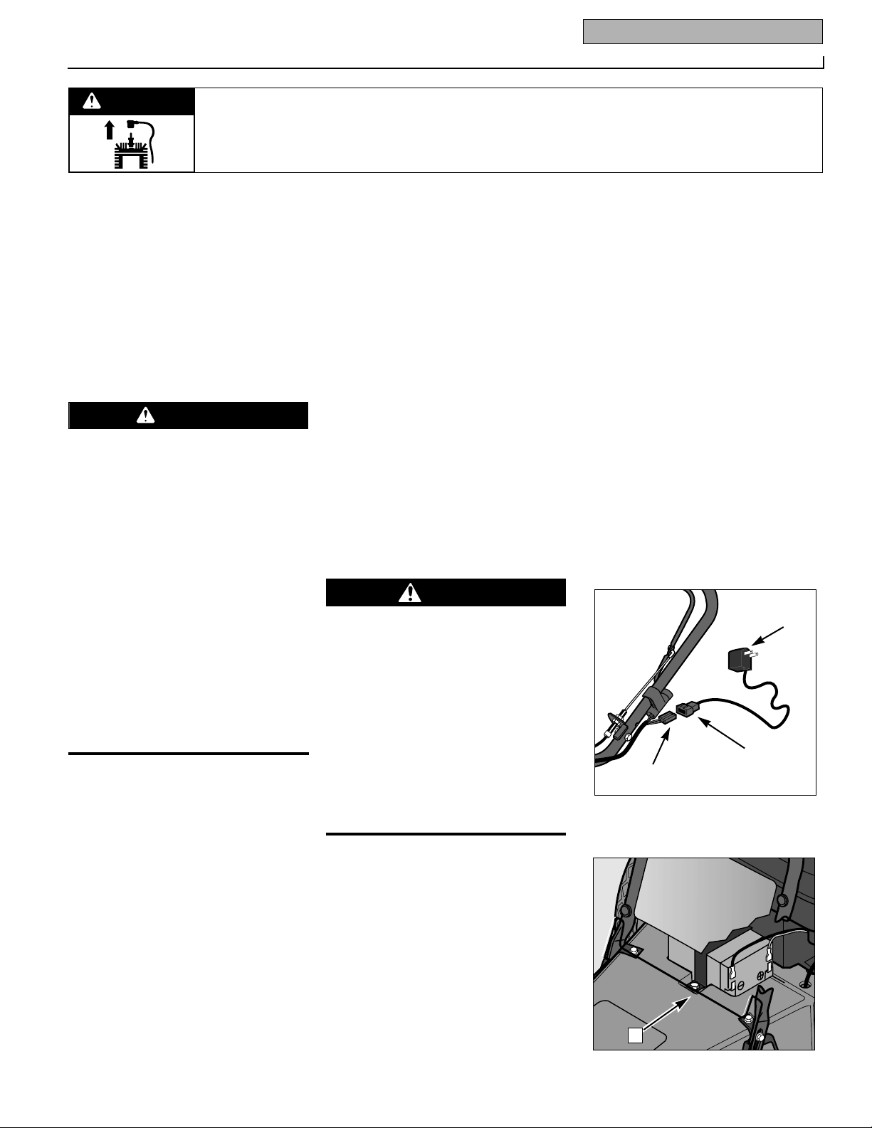
1. Connect the small plug on the battery
charger cord (A, Figure 5-8) to the wire
harness plug (B) located near the
keyswitch.
2. Plug the recharger box (C, Figure 5-8)
into a grounded 220-Volt wall outlet.
3. Charge the battery for 24 hours. After
charging, unplug the recharger box (C,
Figure 5-8) from the wall outlet first, then
disconnect the recharging line plugs (A
and B, Figure 5-8).
BATTERY REPLACEMENT
If the battery no longer takes a charge, or
if it is leaking or otherwise damaged, it
must be replaced.
1. Tilt the debris shield forward.
2. Disconnect the negative (–) black wire
first; then the positive (+) red wire.
3. A clamp secured with two screws
holds the battery to the deck. Remove
screw (D, Figure 5-9), then lift the battery
from under the battery clamp.
4. Position the new battery under the
clamp and replace screw (D).
5. Connect the red wire to the positive (+)
red-coded battery terminal. Then, connect
the black wire to the negative (–) blackcoded battery terminal.
NOTE: Discard battery properly, as
required by regulations in your area.
6. Close the debris shield.
• Never perform maintenance when
engine is running or spark plug wire is
connected, except when instructed to
do so.
• Never store mower with fuel in fuel
tank inside a building where fumes can
reach an open flame or spark, or where
ignition sources are present such as
hot water and space heaters, furnaces,
clothes dryers, stoves, electric motors,
etc. Make sure engine is cool before
storing.
• Drain gasoline outdoors into an
approved container. Do not smoke and
keep fuel away from open flame.
Failure to follow these instructions will
result in serious personal injury or property damage.
WARNING
• Wet conditions can cause an electric
shock hazard during battery charging.
Avoid wet conditions when charging.
• Recharging the battery with improper
equipment could cause a battery explosion. Use only the battery charger
shipped to you. All parts must be fully
stopped and the spark plug wire disconnected and moved away from the
spark plug.
Failure to comply could result in personal injury or property damage.
DANGER
Figure 5-8: Use recharger supplied with
unit.
A
C
B
Figure 5-9: Battery replacement.
D
WARNING
Page 18
16 Section 5: Maintenance
Before inspecting, cleaning or servicing the machine, shut off engine, wait for all moving parts to
come to a complete stop, disconnect spark plug wire and move wire away from spark plug.
Failure to follow these instructions can result in serious personal injury or property damage.
CHANGING TRIMMER LINES
The trimmer lines will wear with use and
eventually require replacement. Also, you
may wish to switch between the thinner
and thicker gauge lines to handle different mowing conditions.
Replace the trimmer lines when they
wear to the point that trimming and
mowing projects take too long and
require too much maneuvering of the
machine. A good rule of thumb is to
change the lines when they reach half
their original length.
Use the extra-heavy duty gauge (.155"
diameter) line when cutting thick, tough
growth. The thinner gauge (.130" diameter) line is for use in less demanding
conditions, and is also recommended for
use near trees or ornamentals to help
prevent girdling (cutting of bark).
TO CHANGE TRIMMER LINES:
1. Stop engine, allow all parts to stop
moving and then disconnect the spark
plug wire. Remove the ignition key on
electric start models. DO NOT tip the
machine. DO NOT touch the metal wear
cup on the bottom of the spindle head.
This surface may be hot.
NOTE: The two line holders on the
trimmer head are permanently secured by
a screw and a nut. Do not attempt to
remove the line holders as it is not necessary to remove them in order to change
the trimmer lines.
2. The trimmer lines can be changed
when the trimmer head is in contact with
the ground. If necessary, you may tip the
unit back slightly for a better view. However, do not tip the unit all the way back
or motor oil may flow to the exhaust area
and the engine may smoke for several
seconds when started.
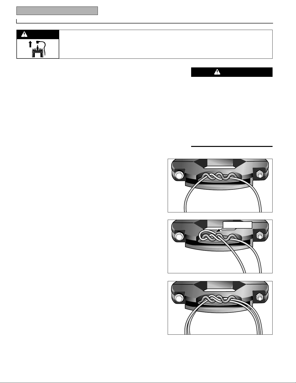
3. Three different line installation patterns are available, as shown in Figures
5-10, 5-11 and 5-12.
4. Simply feed the line through the loops
of the line holder as shown. An equal
amount of line should project out from
each side of the line holder, creating an
overall 22" wide cutting swath. You may
offset both trimmer lines somewhat to
increase the cutting swath up to 25" wide.
However, DO NOT offset the line so that
the overall cutting swath is greater than
25". See Warning statement at right.
IMPORTANT: Whether replacing one or
both lines, they must both be .130" or
.155" in diameter.
5. Repeat steps 2 through 4 to replace
the second trimmer line.
Figure 5-10: Use this single line,
easy-loop pattern for all but the
more difficult cutting conditions.
Figure 5-12: For more difficult
cutting conditions, use two of the
thicker gauge (.155" diameter)
lines in each line holder. Follow
the installation pattern shown in
Figure 5-10.
Figure 5-11: If the lines should
loosen while trimming (especially in more difficult conditions), add a simple reverse loop.
Note that this pattern will result
in a slightly narrower overall cutting swath.
Offsetting the trimmer lines causes the
lines to rotate faster than when they project an equal length on each side. This
increases the chance of loose materials
being dislodged and propelled at high
speeds.
Failure of the operator to wear safety
goggles and appropriate clothing and to
keep bystanders away can result in
severe personal injury or property
damage.
WARNING
Reverse Loop
WARNING
Page 19

Section 5: Maintenance 17
Before inspecting, cleaning or servicing the machine, shut off engine, wait for all moving parts to
come to a complete stop, disconnect spark plug wire and move wire away from spark plug.
Failure to follow these instructions can result in serious personal injury or property damage.
PROBLEM POSSIBLE CAUSE CORRECTION
Engine does not start. 1. Spark plug wire disconnected. 1. Reconnect wire.
2. Defective or incorrectly gapped spark plug. 2. Inspect/replace spark plug.
3. Fuel tank empty. 3. Add fuel.
4. Dirty carburetor or fuel line. 4. Clean carburetor or fuel line.
5. Dirty air cleaner. 5. Clean or replace.
6. Carburetor out of adjustment. 6. Adjust carburetor. See Engine Service Dealer.
7. Engine flooded. 7. Wait several minutes before starting.
8. Engine Throttle Lever in incorrect position. 8. Move Throttle Lever to FAST position.
9. Stale gasoline. 9. Drain old fuel and add fresh fuel.
10. Defective Engine Throttle Lever. 10. See Engine Service Dealer.
11. Dirt or water in fuel tank. 11. See Engine Service Dealer.
Engine runs poorly. 1. Bad spark plug. 1. Inspect/replace spark plug.
2. Dirty air filter. 2. Clean or replace.
3. Carburetor out of adjustment. 3. Adjust carburetor. See Engine Service Dealer.
4. Stale fuel. 4. Drain and replace fuel mixture.
5. Dirt or water in fuel tank. 5. See Engine Service Dealer.
6. Engine cooling system clogged. 6. Clean fins.
Engine overheats. 1. Engine cooling system clogged. 1. Clean air cooling areas and behind debris shield.
2. Carburetor out of adjustment. 2. Adjust Carburetor. See Engine Service Dealer.
Engine does not shut off. Throttle control misadjusted. See Engine Service Dealer.
.
Poor mowing performance. 1. Line length is too short or too long. 1. Adjust line length to 18" long. When less
than 1/2 this length, replace the line.
2. Cutting height is too high or low for height 2. Adjust cutting height to approximately 1/3
of grass being cut. of the length of the grass.
3. Engine not set at FAST speed. 3. Move Engine Throttle Lever to FAST (Rabbit).
Trimmer/Mower vibrates. 1. Trimming head mounting bolt loose. 1. Tighten bolt.
2. Line lengths are substantially different. 2. Adjust lines to approximately equal lengths.
3. Loose nuts or bolts. 3. Check all bolts and nuts, including engine bolts.
4. Broken spindle head or trimmer head. 4. Replace broken part.
Trimmer head does not Incorrect line installation for mowing conditions. See Changing Trimmer Lines in Section 5.
retain line.
Trimmer Head does not 1. Head bolts may be loose. 1. Tighten head bolts to 75 in/lbs.
retain height setting. 2. Head is worn. 2. Replace head assembly.
Electric Starter does not 1. Wires to battery unconnected. 1. Reconnect wires.
start engine (electric start 2. Battery not charged. 2. Charge battery.
models only). 3. Broken wire in wiring harness. 3. Replace wiring harness.
4. Malfunctioning starter motor. 4. Contact local engine dealer.
Battery does not charge 1. Broken wire in engine recharging circuit. 1. See Engine Service Dealer.
during engine operation 2. Malfunctioning engine recharging system. 2. See Engine Service Dealer.
(electric start models). 3. Dead battery. 3. Replace battery.
Battery charger does not 1. Broken battery lead. 1. Replace battery lead.
charge battery (electric 2. Broken battery charger wire. 2. Replace battery charger.
start models). 3. Dead battery. 3. Replace battery.
TROUBLESHOOTING
Before performing any of the corrections in this Troubleshooting Chart, refer to the appropriate information contained in this
Manual or the Engine Owner’s Manual for the correct safety precautions and servicing procedures. Contact your local authorized Engine Service Dealer for engine service. Contact your local authorized dealer for service problems with the machine.
WARNING
Page 20
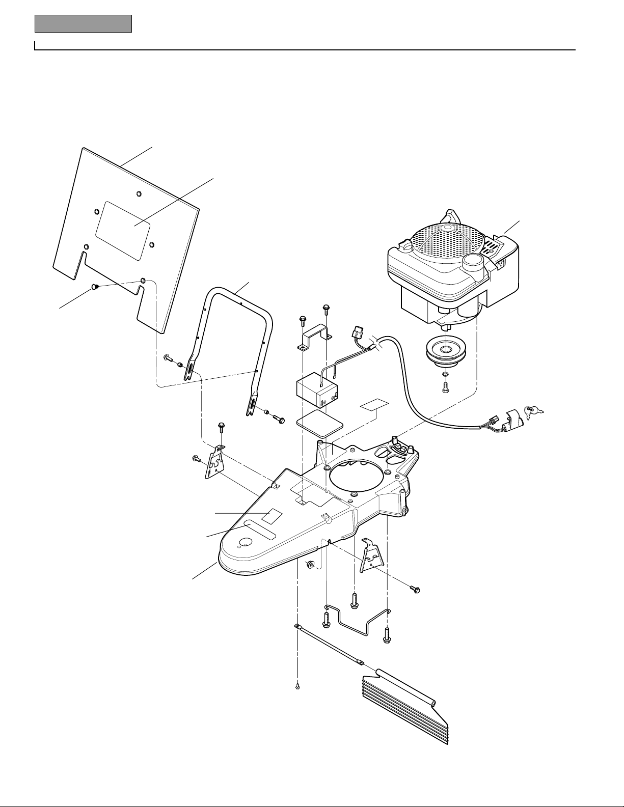
18 Parts List
Models 52068 & 52069
DRAWING NO. 1
1
2
3
4
5
5
5
5
5
5
7
8
9
10
11
12
13
26
17
17
17
16
20
21
22
23
24
25
15
18
19
14
14
6
6
Page 21

Parts List 19
Models 52068 & 52069
1 1917765 Debris Guard ............................................ 1
2 1918741 Decal-Logo .............................................. 1
3 1918415 Push-in Fastener....................................... 5
4 1917407001 Debris Guard Support............................... 1
5 1754128 Hex Flange Screw, 1/4-20 x 3/4................ 8
6 9534 Spacer ...................................................... 2
7 * Engine....................................................... 1
8 1903584 Decal-Hot Surface Warning ...................... 1
9 1917728 Engine Pulley............................................ 1
10 1100243 Spring Lock Washer................................. 1
11 1100009 Hex Hd. Screw, 3/8-24 x 1, Grade 5 ......... 1
12 1918814 Deck (Incl. Refs. 13 & 26)........................ 1
13 1903588 Decal-Warning.......................................... 1
14 1917144001 Hood Bracket............................................ 2
Ref. # Part # Description Qty.
*
Order parts from your local authorized engine dealer. Refer to engine
for model/type number.
15 1186389 Flange Lock Nut, 1/4-20 ........................... 2
16 1917574 Belt Guide................................................. 1
17 1768194 Hex Hd. Screw, 3/8-16 x 1-1/2 ................. 3
18 1917154 Deflector Flap............................................ 1
19 1917155 Rod........................................................... 1
20 1909647 Battery (A)................................................ 1
21 1915268 Battery Pad (A)......................................... 1
22 1915204001 Battery Clamp (A)..................................... 1
23 90063 Hex Flange Screw (A), 5/16-18 x 1........... 2
24 1918055 Wire Harness (A)...................................... 1
25 96520 Ignition Key (A)......................................... 2
26 1916424 Decal - Warning........................................ 1
-- 1904534 Muffler Guard ........................................... 1
-- 1983662 Screw (for Muffler Guard) ........................ 2
Ref. # Part # Description Qty.
PARTS LIST – DRAWING NO. 1
(A) Model 52069
(B) Model 52068
Page 22
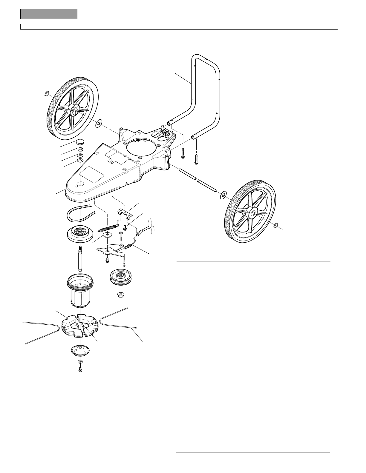
20 Parts List
Models 52068 & 52069
DRAWING NO. 2
See DRAWING
NO. 1
See DRAWING
NO. 3
See ACCESSORIES
AND KITS
2
2
1
1
3
3
4
7
8
9
10
11
12
13
14
15
16
27
17
18
22
23
24
25
26
18
18
19
20
21
6
1 1917778 Wheel/Tire Assembly.............................. 2
2 1917593 Locking Retaining Ring.......................... 2
3 1917775 Flat Washer............................................ 2
4 1917258 Axle........................................................ 1
6 1918069 Self-Tap Screw, 5/16-18 x 2................... 2
7 1917588 Cap Plug................................................. 1
8 1734514 Hex Lock Nut, 1/2-13............................. 1
9 9928 Belleville Washer.................................... 1
10 1917745 Hardened Washer................................... 1
11 1917579 V-Belt..................................................... 1
12 1918246 Spindle Head Adapter (Incl. Bearing) ..... 1
13 1917581 Spindle Shaft.......................................... 1
14 1918329 Spindle Head Assembly (Incl. Bearing,
Insert, and Refs. 16, 17, 18)............... 1
15 1918393 Trimmer Head Assembly (Incl. Ref. 27). 1
16 1915220001 Wear Cup ............................................... 1
17 1917599 Square Washer....................................... 1
18 1724491 Self-Tap Screw, 5/16-18 x 3/4................ 3
19 1917781 Cable Bracket ......................................... 1
20 1910849 Idler Spring............................................ 1
21 1917746 Flat Washer............................................ 1
22 1917589 Control Cable - Trimmer Head ............... 1
23 1910857 Button Hd. Screw, 3/8-16 x 1-1/2........... 1
24 1917782 Idler Arm................................................ 1
25 1910855 Idler Pulley............................................. 1
26 1186393 Flange Lock Nut, 3/8-16......................... 1
27 1918332 Rubber Shim Kit (2 shims per kit).......... 1
Ref. # Part # Description Qty.
PARTS LIST – DRAWING NO. 2
Page 23
Parts List 21
Models 52068 & 52069
DRAWING NO. 3
1
4
5
2
3
6
6
8
7
9
12
13
13
13
14
15
16
14
10
11
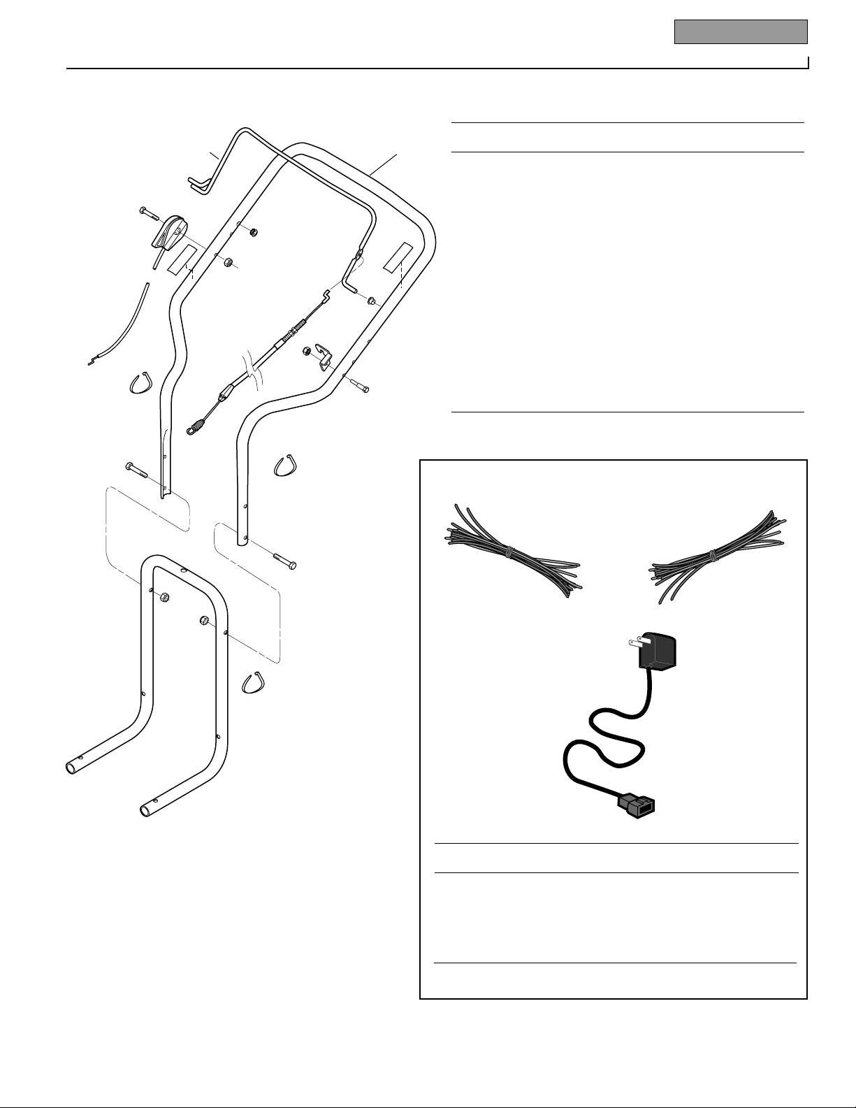
1 1918283 Upper Handlebar (Incl. Refs. 2 & 3)....... 1
2 1915889 Decal–Bail Engage/Disengage................ 1
3 1918304 Decal–Throttle ....................................... 1
4 1918070001 Control Bail–Trimmer Head ................... 1
5 1917589 Cable Assembly–Trimmer Head............. 1
6 1908677 Bushing.................................................. 2
7 1749977001 Cable Bracket ......................................... 1
8 1983658 Hex Hd. Screw, 1/4-20 x 1-1/8............... 1
9 1185814 Hex Flange Lock Nut, 1/4-20.................. 1
10 1918081 Throttle Lever & Cable Assembly........... 1
11 1100807 Hex Hd. Screw, 1/4-20 x 2 ..................... 1
12 1110106 Hex Lock Nut, 1/4-20............................. 1
13 1763682 Cable Tie................................................. 3
14 1100799 Hex Hd. Screw, 5/16-18 x 1-1/2............. 2
15 1917145001 Handlebar Support ................................ 1
16 1732499 Hex Lock Nut, 5/16-18........................... 2
Ref. # Part # Description Qty.
PARTS LIST – DRAWING NO. 3
ACCESSORIES AND KITS
1
2
3
Ref. # Part # Description Qty.
1 1904476 Trimmer String Kit, .155" diameter line
(24 pieces) ........................................... N/I
2 1904477 Trimmer String Kit, .130" diameter line
(24 pieces) ........................................... N/I
3 1902274 Battery Charger (for electric start model) . 1
N/I Not included with unit, order separately.
Page 24
1905587 (2/01) Printed in U.S.A. © 2001 Garden Way Incorporated
CUSTOMER SERVICE INFORMATION
Owner Registration Card
Please fill out and mail the enclosed owner
registration card. The purpose of this card is
to register each unit at the factory so that we
can provide you with warranty benefits and
informational bulletins.
Warranty Service
The warranty statement is included in the unit’s literature
package.
Model/Serial Numbers
A Model/Serial Numbers decal is located on the side of the
deck. For ready reference, record these numbers in the
spaces below.
Date of Purchase:
Model Number:
Serial Number:
Authorized Dealer Information
If you purchased your unit from an authorized dealer, record
the dealer’s address and phone number below for ready reference:
Dealer Name:
Address:
Phone:
IMPORTANT:
Left and right sides of the unit are determined by standing
behind the unit, in the operator’s position, and facing in the
direction of forward travel.
NOTICE:
We reserve the right to change specifications, add
improvements or discontinue the manufacture of any of our
equipment without notice or obligation to purchasers of our
equipment.
M
I
A
L
M
I
A
L
Customer Service and Technical Service
If you have questions or problems with the
unit, contact your local dealer or the factory.
(When calling or writing, provide the
Model/Serial Numbers of the unit.)
Replacement Parts
Factory specified replacement parts are
available from your authorized dealer.
When ordering parts, be sure to provide
the following:
• Model/Serial Numbers of the unit.
• Part number of the part needed.
• Part Description.
• Quantity needed.
NOTE: All replacement parts must conform to our rigid quality
specifications. Although some replacement parts we provide
may vary slightly in shape, color or texture from the original
parts, any variations will not affect the fit or performance of
these parts on your unit.
Engine Service and Repair
For engine service or repair, contact your
nearest authorized engine dealer (look in the
Yellow Pages under “Engines–Gasoline”).
The engine is warranted by the engine manufacturer. Any unauthorized work performed
on the engine during the warranty period
may void this warranty. For complete
details on the engine warranty, refer to the
Engine Owner’s Manual.
For customer assistance, contact your nearest authorized dealer or:
GARDEN WAY INCORPORATED • 1 Garden Way • Troy, New York 12180
Customer Service: 1-800-437-8686 • Technical Service: 1-800-520-5520 • Parts Service: 1-800-648-6776
• FAX: (518) 233-4622
Outside the United States and Canada:
Customer Service: (518) 233-4807 • Technical Service: (518) 233-4808 • Parts Service: (518) 233-4806 • FAX (518) 233-4622
We urge using only genuine replacement parts, which
meet all the latest requirements. Replacement parts
manufactured by others could present safety hazards,
even though they may fit on the unit.
WARNING
 Loading...