

Page 1
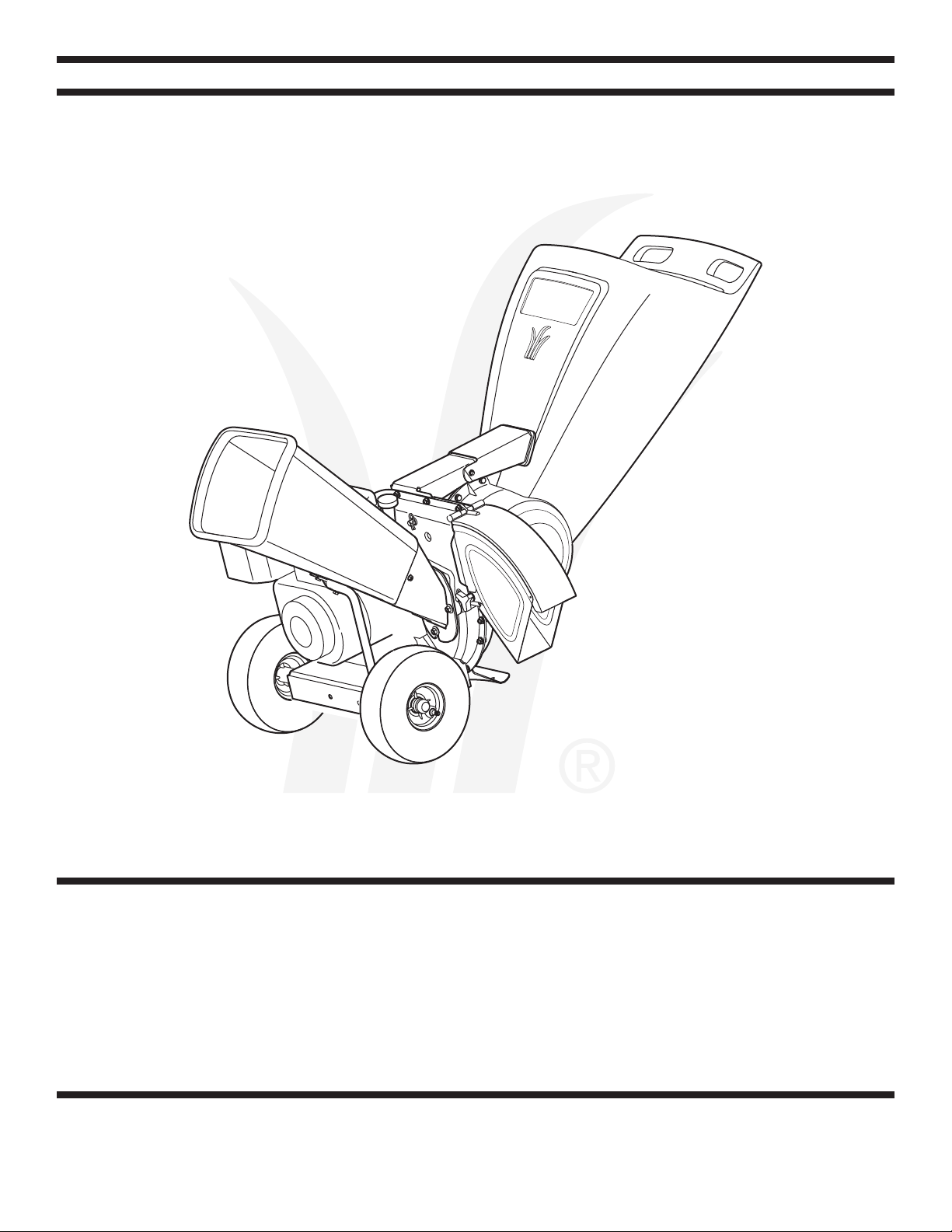
Safety • Assembly • Operation • Tips & Techniques • Maintenance • Troubleshooting • Parts Lists • Warranty
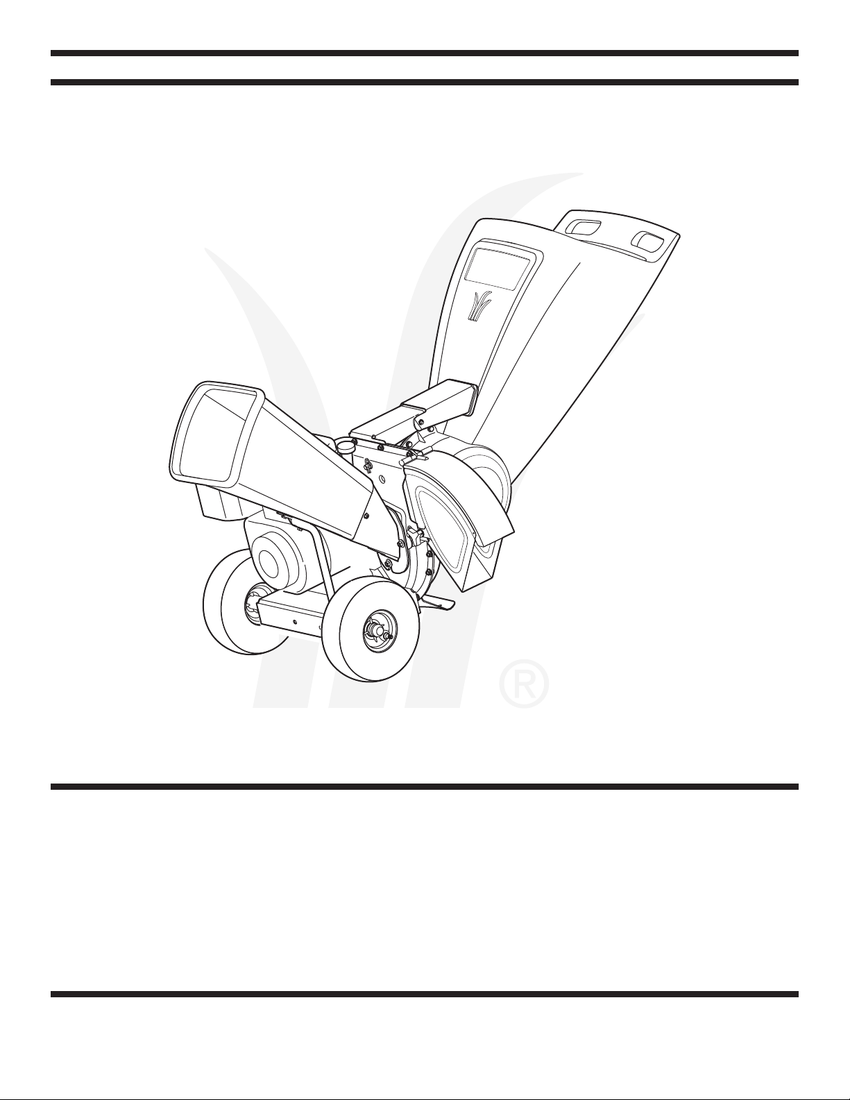
OPERATOR’S MANUAL
*Model Series 460 Shown
Chipper Shredder — Model Series 450 and 460
IMPORTANT
READ SAFETY RULES AND INSTRUCTIONS CAREFULLY BEFORE OPERATION
Warning: This unit is equipped with an internal combustion engine and should not be used on or near any unimproved forest-covered, brush-
covered or grass-covered land unless the engine’s exhaust system is equipped with a spark arrester meeting applicable local or state laws (if any).
If a spark arrester is used, it should be maintained in effective working order by the operator. In the State of California the above is required by law
(Section 4442 of the California Public Resources Code). Other states may have similar laws. Federal laws apply on federal lands. A spark arrester
for the muffler is available through your nearest engine authorized service dealer or contact the service department, P.O. Box 361131 Cleveland,
Ohio 44136-0019.
PRINTED IN U.S.A.
MTD LLC, P.O. BOX 361131 CLEVELAND, OHIO 44136-0019
FORM NO. 770-10048J
5/9/2007
Page 2
This Operator’s Manual is an important part of your new chipper shredder. It will help you assemble, pre-
pare and maintain the unit for best performance. Please read and understand what it says.
Table of Contents
Customer Support .............................................. 2
Safety Labels ......................................................3
Safe Operation Practices ................................... 4
Setting Up Your Chipper Shredder .................... 6
Operating Your Chipper Shredder ................... 10
Finding and Recording Model Number
BEFORE YOU START ASSEMBLING
YOUR NEW EQUIPMENT,
please locate the model plate on the equipment and copy
the information to the sample model plate provided to the
right. You can locate the model plate by standing behind the
unit and looking down at the frame below the engine. This
information will be necessary to use the manufacturer’s web
site and/or obtain assistance from the Customer Support
Department or an authorized service dealer.
Maintaining Your Chipper Shredder ................ 12
Troubleshooting ................................................ 14
Parts List ........................................................... 16
Warranty ............................................................ 20
Español .............................................................. 21
Model Number Serial Number
Customer Support
Please do
purchased, without first contacting Customer Support.
If you have difficulty assembling this product or have any questions regarding the controls, operation, or maintenance of this
unit, you can seek help from the experts. Choose from the options below:
1. Visit mtdproducts.com. Click on the Customer Service menu option.
2. Phone a Customer Support Representative at
3. The
engine manufacturer is responsible for all engine-related issues with regards to performance, power-rating, specifica-
tions, warranty and service. Please refer to the engine manufacturer’s Owner’s/Operator’s Manual, packed separately with
your unit, for more information.
NOT
return the unit to the retailer from which it was
1.800.800.7310. Spanish speaking agents are available.
2
Page 3
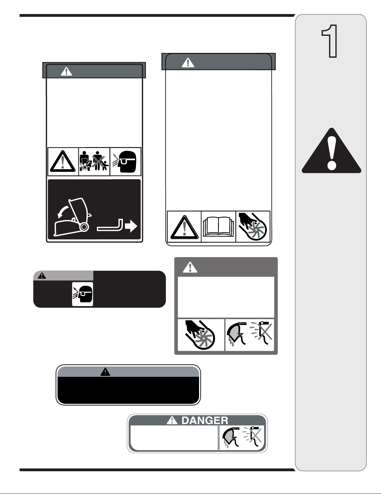
Safety Labels Found On Your
DO NOT OPERATE THIS MACHINE
UNLESS THE CHUTE DEFLECTOR
HAS BEEN PROPERLY INSTALLED.
WARNING
• Do not transport machine while
engine is running.
• Shredder should not be towed on any
street, highway or public road.
• Do not tow shredder over 10 m.p.h.
• Do not allow anyone to sit or ride on
shredder.
• Do not tow shredder for long distances.
• Before towing, be certain the shredder
is correctly attached to towing vehicle.
S30228
DANGER
TO
AVOID SERIOUS INJU
RY
:
•
Read the
o
wner's ma
n
ual(s) be
f
ore star
ting and
using
unit.
• K
eep all shields and gua
r
ds in place and secure
ly
attached
.
• K
eep hands
,
f
eet
,
face,
c
lothing and long hair out of
Shredder Hoppe
r,
Chipper Chute and Dis
char
ge
C
hute while the engine is running
.
R
otating cutting
b
lades inside these openings will cause serious
per
sonal inju
ry if contacted
.
Material being
pr
ocessed
ma
y bounce ba
ck
fr
om inlet openings or be th
ro
wn
fr
om the dis
char
ge c
hut
e. Long hair or loose
c
lothing
ma
y be pulled su
c
ked into the inlet openings
.
•
Do not place bran
c
hes o
ver 1/2 in
ch diameter into
the la
rg
e Shr
e
d
der Hoppe
r.
Bran
c
hes
o
ver 1/2 in
ch in
diameter should be placed in the Small Chipper
Chut
e.
•
If the
c
hipped shre
d
der jams or becomes
cl
ogged,
immediate
ly
shut off the engine and wait
f
or all
mo
ving par
ts to come to a complete stop be
f
ore
c
learing
.
•
Do not install re
m
ov
e,
adjust
,
or service the
dischar
ge screen or
a
ny
other pa
rt
while the engine
is running
.
Blade contact can occu
r.
DANGER
TO
AV
OID SERIOUS INJU
RY
:
•
Do not operate on un
e
ven
g
r
ound where unit is
unstable
.
Do not operate on
p
a
vement
,
gra
vel or
other ha
rd
surfaces since objects can rico
c
het
and cause inju
ry
.
• T
o
av
oid a fire haza
rd
,
keep le
a
ves
,
grass
,
and other
comb
ustible materials
aw
ay
fr
om hot engine and
mu
ffle
r.
• K
eep
children and othe
rs
aw
ay
fr
om area of
operatio
n
.
• W
ear app
ro
ved safety glasses
,
glo
ves and ear
pr
otectio
n
.
INSTR
UCTIONS:
TO
RAISE AND
L
O
WER HOPPER
TO AVO I D
EY E I NJ U RY,
WE A R SA F TE Y
GL A SS ES .
DO NOT DEPOSIT
MATERIAL LARGER THAN
1/2" DIAMETER IN LARGE
SHREDDER HOPPER.
THIS MAY DAMAGE
MACHINE.
WA R N I N G
DANGER
• ROTATING CUTTING BLADES.KEEP H AN DS
AND FEET OUT OF OPENING WHILE
MACHINE IS RUN NIN G.
• DO NOT OPERATE THIS MACHI NE UNL ESS
TH E CHUTE DEFLECTOR HAS BEEN
PROPERLY INSTALLED AND IS SECURED
WITH TH E H A N D K NOB S.
Chipper Shredder
1
Safety
Labels
WARNING
DO NOT remove safety
(or any) labels from
chipper shredder for
any reason.
3
Page 4
WARNING: Engine Exhaust, some of its constituents, and certain vehicle components contain or emit chemicals known to State of California to cause cancer and
birth defects or other reproductive harm.
2
Safe
Operation
Practices
WARNING
This symbol points
out important safety
instructions which, if
not followed, could
endanger the personal
safety and/or property
of yourself and others.
Read and follow all
instructions in this
manual before attempting to operate
this machine. Failure
to comply with these
instructions may result
in personal injury. When
you see this symbol.
HEED ITS WARNING!
Your Responsibility
Restrict the use
of this power machine
to persons who read,
understand
and follow the warnings
and instructions
in this manual
and on the machine.
DANGER: This machine was built to be operated according to the rules for safe operation in this
manual. As with any type of power equipment, carelessness or error on the part of the operator can
result in serious injury. This machine is capable of amputating hands and feet and throwing objects.
Failure to observe the following safety instructions could result in serious injury or death.
Training
1. Read, understand, and follow all instructions on the ma-
chine and in the manual(s) before attempting to assemble
and operate. Keep this manual in a safe place for future
and regular reference and for ordering replacement parts.
2. Be familiar with all controls and their proper operation.
Know how to stop the machine and disengage them
quickly.
3. Never allow children under 16 years old to operate this
machine. Children 16 years old and over should read and
understand the operation instructions and safety rules in
this manual and should be trained and super vised by a
parent.
4. Never allow adults to operate this machine without proper
instruction.
5. Keep bystanders, helpers, pets, and children at least
75 feet from the machine while it is in operation. Stop
machine if anyone enters the area.
6. Never run an engine indoors or in a poorly ventilated area.
Engine exhaust contains carbon monoxide, an odorless
and deadly gas.
7. Do not put hands and feet near rotating parts or in the
feeding chambers and discharge opening. Contact with
the rotating impeller can amputate fingers, hands, and
feet.
8. Never attempt to unclog either the feed intake or
discharge opening, remove or empty bag, or inspect and
repair the machine while the engine is running. Shut the
engine off and wait until all moving parts have come to a
complete stop. Disconnect the spark plug wire and ground
it against the engine.
1. Thoroughly inspect the area where the equipment is to
be used. Remove all rocks, bottles, cans, or other foreign
objects which could be picked up or thrown and cause
personal injury or damage to the machine.
2. Always wear safety glasses or safety goggles during opera
tion or while performing an adjustment or repair, to protect
eyes. Thrown objects which ricochet can cause serious
injury to the eyes.
3. Wear sturdy, rough-soled work shoes and close-fitting
slacks and shirts. Loose fitting clothes or jewelry can be
caught in movable parts. Never operate this machine
in bare feet or sandals. Wear leather work gloves when
feeding material in the chipper chute.
4. Before starting, check all bolts and screws for proper tight
ness to be sure the machine is in safe working condition.
Also, visually inspect machine for any damage at frequent
intervals.
5. Maintain or replace safety and instructions labels, as
necessary.
6. To avoid personal injury or property damage use extreme
care in handling gasoline. Gasoline is extremely flammable
and the vapors are explosive. Serious personal injury can
occur when gasoline is spilled on yourself or your clothes
which can ignite. Wash your skin and change clothes
immediately.
a. Use only an approved gasoline container.
b. Extinguish all cigarettes, cigars, pipes, and other
sources of ignition.
c. Never fuel machine indoors.
d. Never remove gas cap or add fuel while the engine is hot
or running.
e. Allow engine to cool at least two minutes before refuel
ing.
f. Never over fill fuel tank. Fill tank to no more than 1/2
inch below bottom of filler neck to provide space for fuel
expansion.
g. Replace gasoline cap and tighten securely.
h. If gasoline is spilled, wipe it of f the engine and equip
ment. Move machine to another area. Wait 5 minutes
before starting the engine.
i. Never store the machine or fuel container inside where
there is an open flame, spark, or pilot light (e.g. furnace,
water heater, space heater, clothes dr yer, etc.)
j. To reduce a fire hazard, keep machine free of grass,
leaves, or other debris build-up. Clean up oil or fuel
spillage and remove any fuel soaked debris.
k. Allow machine to cool at least 5 minutes before storing.
Preparation
-
-
-
-
4
Page 5
Operation
1. Do not put hands and feet near rotating parts or in the
feeding chambers and discharge opening. Contact with the
rotating impeller can amputate fingers, hands, and feet.
2. Before starting the machine, make sure the chipper chute,
feed intake, and cutting chamber are empty and free of all
debris.
3. Thoroughly inspect all material to be shredded and remove
any metal, rocks, bottles, cans, or other foreign objects
which could cause personal injury or damage to the
machine.
4. f it becomes necessary to push material through the
shredder hopper, use a small diameter stick. Do not use
your hands or feet.
5. f the impeller strikes a foreign object or if your machine
should start making an unusual noise or vibration,
immediately shut the engine off. Allow the impeller to come
to a complete stop. Disconnect the spark plug wire, ground
it against the engine and per form the following steps:
a. Inspect for damage.
b. Repair or replace any damaged parts.
c. Check for any loose parts and tighten to assure
continued safe operation.
6. Do not allow an accumulation of processed material to build
up in the discharge area. This can prevent proper discharge
and result in kickback of material through the feed opening.
7. Do not attempt to shred or chip material larger than
specified on the machine or in this manual. Personal injury
or machine damage could result.
8. Never attempt to unclog either the feed intake or discharge
opening while the engine is running. Shut the engine off,
wait until all moving parts have stopped, disconnect the
spark plug wire and ground it against the engine before
clearing debris.
9. Never operate without the shredder hopper, chipper chute,
or chute deflector properly attached to the machine. Never
empty or change discharge bag while the engine is running.
10. Keep all guards, deflectors and safety devices in place and
operating properly.
11. Keep your face and body back and to the side of the chipper
chute while feeding material into the machine to avoid
accidental kickback injuries.
12. Never operate this machine without good visibility or light.
13. Do not operate this machine on a paved, gravel or non-level
surface.
14. Do not operate this machine while under the influence of
alcohol or drugs.
15. Muffler and engine become hot and can cause a burn. Do
not touch.
16. Never pick up or carry machine while the engine is running.
Maintenance & Storage
1. Never tamper with safety devices. Check their proper
operation regularly.
2. Check bolts and screws for proper tightness at frequent
intervals to keep the machine in safe working condition.
Also, visually inspect machine for any damage and repair, if
needed.
3. Before cleaning, repairing, or inspecting, stop the engine
and make certain the impeller and all moving parts have
stopped. Disconnect the spark plug wire and ground it
against the engine to prevent unintended starting.
4. Do not change the engine governor settings or overspeed
the engine. The governor controls the maximum safe
operating speed of the engine.
5. Maintain or replace safety and instruction labels, as neces
sary.
6. Follow this manual for safe loading, unloading, transporting,
and storage of this machine.
7. Never store the machine or fuel container inside where
there is an open flame, spark or pilot light such as a water
heater, furnace, clothes dryer, etc.
8. Always refer to the operator’s manual for proper instructions
on off-season storage.
9. If the fuel tank has to be drained, do this outdoors.
10. Observe proper disposal laws and regulations for gas, oil,
etc. to protect the environment.
Do not modify engine
To avoid serious injury or death, do not modify engine in any
way. Tampering with the governor setting can lead to a runaway
engine and cause it to operate at unsafe speeds. Never tamper
with factory setting of engine governor.
Notice regarding Emissions
Engines which are certified to comply with California and federal
EPA emission regulations for SORE (Small Off Road Equipment)
are certified to operate on regular unleaded gasoline, and may
include the following emission control systems: Engine Modification (EM) and Three Way Catalyst (TWC) if so equipped.
Your Responsibility
Restrict the use of this power machine to persons who read, understand and follow the warnings and instructions in this manual
and on the machine.
2
Safe
Operation
Practices
-
WARNING
This symbol points
out important safety
instructions, which if
not followed, could
endanger the personal
safety and/or property
of yourself and others.
Read and follow all
instructions in this manual before attempting to
operate this machine.
Failure to comply with
these instructions may
result in personal injury.
When you see this
symbol.
HEED IT’S WARNING!
Your Responsibility
Restrict the use
of this power machine
to persons who read,
understand
and follow the warnings
and instructions
in this manual
and on the machine.
5
Page 6
3
Setting Up
Your Chipper
Shredder
IMPORTANT
This unit is shipped
without gasoline or
oil in the engine. Be
certain to service
engine with gasoline
and oil as instructed
in the separate engine
manual before operat-
ing your machine.
NOTE: All references
in this manual to the
left or right side of
the chipper shredder
is from the operating
position only. Exceptions, if any, will be
specified.
IMPORTANT: This unit is shipped without gasoline or oil
in the engine. Be certain to service engine with gasoline
A
and oil as instructed in the separate engine manual
before operating your machine.
Loose Parts In Carton
a. Hopper Assembly d. Bag
b. Chute Deflector e. Safety Glasses
c. Chipper Chute f. Engine Oil
Attaching The Hopper
Assembly
B
C
Figure 3-1
A
B
Figure 3-2
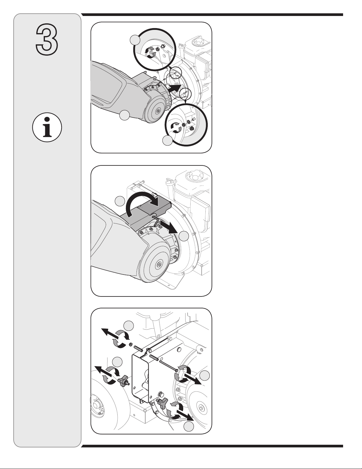
1. a. Remove six hex nuts and washers from the weld
studs on the impeller housing. Do not remove the
support plate. See Figure 3-1.
b. Place hopper assembly into position in front of
impeller housing, aligning holes in hopper assembly
collar with weld studs.
c. Slide hopper assembly onto weld studs and replace
washers and hex nuts. Do not tighten completely.
2. a. Lift hopper assembly up to impeller bracket
assembly.
b. Slide the release rod out slightly to hook the hopper
bracket onto the rod. See Figure 3-2.
c. Tighten the six hex nuts that secure hopper
assembly to impeller housing and also tighten the
hex nuts that secure hopper bracket to hopper
assembly.
NOTE: This Operators
Manual covers a range
of product specifications for various
models. Characteristics
and features discussed
and/or illustrated in this
manual may not be applicable to all models.
MTD LLC reserves the
right to change product
specifications, designs
and equipment without
notice and without
incurring obligation.
B
A
B
A
Figure 3-3
6
Page 7
Attaching The Chute Deflector
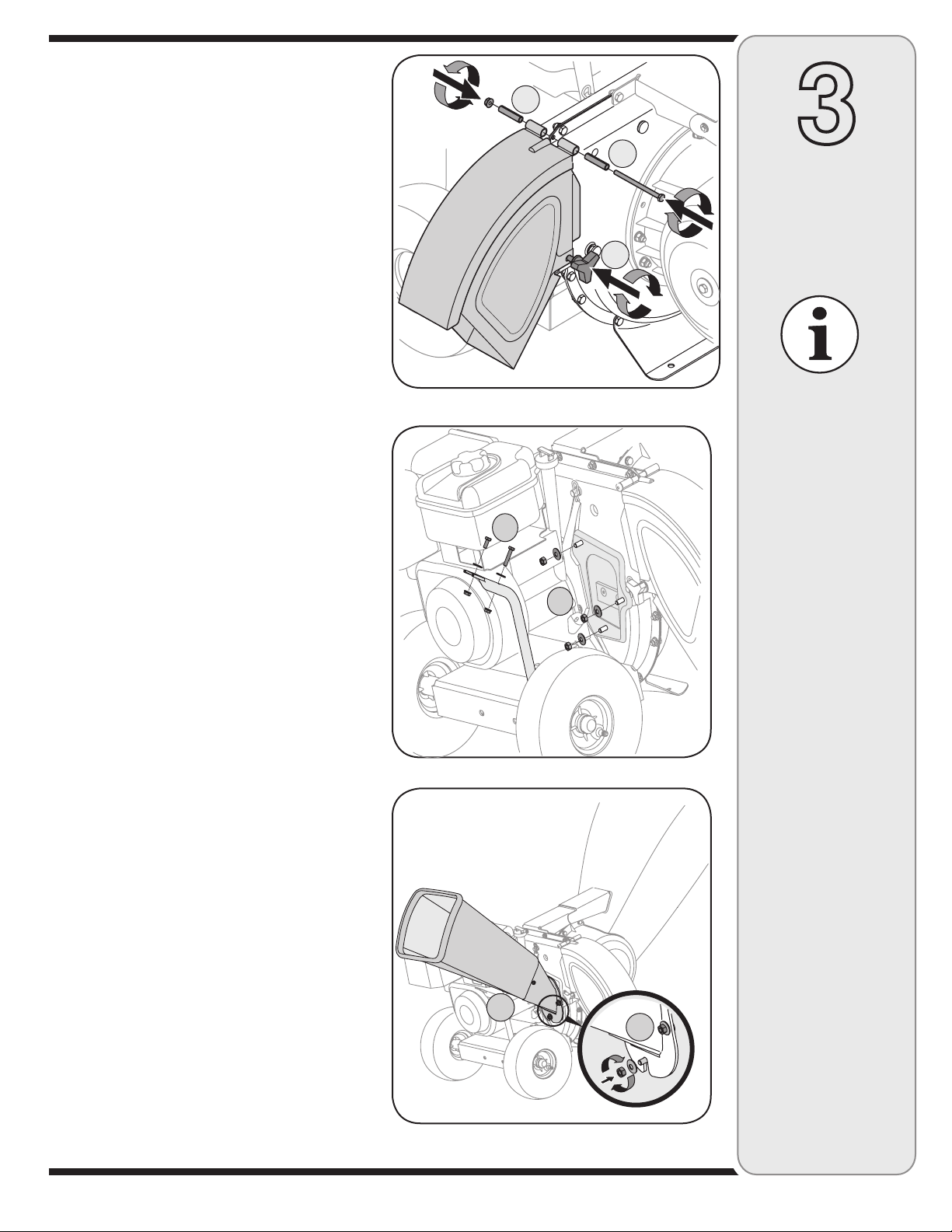
3. a. Remove the wing knobs from each side of the lower
impeller housing.
b. Remove the hex lock nut, spacers, and hex bolt from
the top of the impeller housing. See Figure 3-3.
4. a. Align the chute deflector in position on the
discharge opening and insert hex bolt with spacer
through hinge on chute deflector (spacers fit inside
of hinges). See Figure 3-4.
b. Place second spacer over hex bolt inside other
hinge and secure with hex lock nut.
c. Secure both sides of chute deflector to impeller
housing using wing knobs previously removed.
Attaching The Chipper Chute
(Model Series 460)
5. a. Remove the three cupped washers and hex nuts
from weld studs around the opening on the side of
the impeller housing. See Figure 3-5.
b. Remove the hex bolts, flat washers, and lock nuts
from the two holes on the upper end of the support
brace.
6. a. Align the chipper chute over the weld studs, so the
slot in the bottom of the chute is facing down.
b. Secure chipper chute with the three cupped
washers (cupped side against the chipper chute)
and hex nuts previously removed. Do not tighten
the nuts at this time. See Figure 3-6.
B
Figure 3-4
B
3
A
Setting Up
Your Chipper
C
A
Shredder
IMPORTANT
This unit is shipped
without gasoline or
oil in the engine. Be
certain to service
engine with gasoline
and oil as instructed
in the separate engine
manual before operat-
ing your machine.
Fgure 3-5
A
Figure 3-6
NOTE: All references
in this manual to the
left or right side of
the chipper shredder
is from the operating
position only. Exceptions, if any, will be
specified.
NOTE: This Operators
Manual covers a range
of product specifications for various
models. Characteristics
and features discussed
and/or illustrated in this
manual may not be applicable to all models.
B
MTD LLC reserves the
right to change product
specifications, designs
and equipment without
notice and without
incurring obligation.
7
Page 8

3
Setting Up
Your Chipper
Shredder
IMPORTANT
This unit is shipped
without gasoline or
oil in the engine. Be
certain to service
engine with gasoline
and oil as instructed
in the separate engine
manual before operat-
ing your machine.
7. The chipper shredder was shipped with one end of
the support brace already secured to the lower frame.
Loosen but do not remove the bolts securing the brace
to the frame. See Figure 3-7.
a. Align the holes in the chute with the holes in the top
of the brace and attach brace to chipper chute with
A
hardware previously removed. Tighten securely.
b. Tighten the bolts securing the support brace to the
frame.
c. Tighten the three nuts on the weld studs holding
the chipper chute to the impeller housing.
Attaching The Chipper Chute
B
C
8. a. Remove the three cupped washers and hex nuts
Figure 3-7
(Model Series 450)
from weld studs around the opening on the side of
the impeller housing. See Figure 3-8.
NOTE: All references
in this manual to the
left or right side of
the chipper shredder
is from the operating
position only. Exceptions, if any, will be
specified.
NOTE: This Operators
Manual covers a range
of product specifications for various
models. Characteristics
and features discussed
and/or illustrated in this
manual may not be applicable to all models.
MTD LLC reserves the
right to change product
specifications, designs
and equipment without
notice and without
incurring obligation.
Figure 3-8
8
Page 9
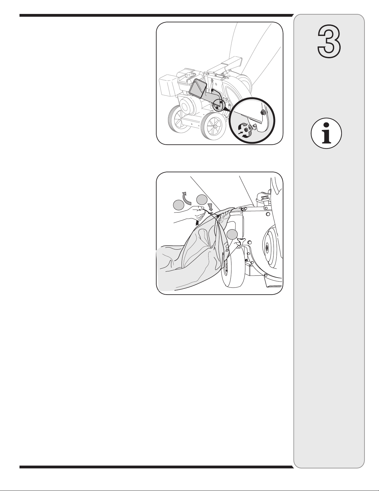
9. a. Align the chipper chute over the weld studs, so the
slot in the bottom of the chute is facing down.
b. Secure chipper chute with the three cupped
washers (cupped side against the chipper chute)
and hex nuts previously removed. Tighten the nuts
at this time. See Figure 3-9.
3
Attaching The Bag
10. To attach the bag:
a. Place the opening of the bag completely over the
chute deflector.
b. Pull on the drawstring until the bag is tight around
chute deflector opening.
c. Clip drawstring back on itself, tight against chute
deflector to secure into position. See Figure 3-10.
Setting Up
Your Chipper
Shredder
Figure 3-9
IMPORTANT
This unit is shipped
without gasoline or
oil in the engine. Be
certain to service
B
C
A
engine with gasoline
and oil as instructed
in the separate engine
manual before operat-
ing your machine.
Figure 3-10
NOTE: All references
in this manual to the
left or right side of
the chipper shredder
is from the operating
position only. Exceptions, if any, will be
specified.
NOTE: This Operators
Manual covers a range
of product specifications for various
models. Characteristics
and features discussed
and/or illustrated in this
manual may not be applicable to all models.
MTD LLC reserves the
right to change product
specifications, designs
and equipment without
notice and without
incurring obligation.
9
Page 10
4
Operating
Your Chipper
Shredder
WARNING
The operation of any
chipper shredder
can result in foreign
objects being thrown
into the eyes, which
can damage your
eyes severely. Always
wear the safety
glasses provided
with this unit or eye
shields before chip-
ping or shredding
and while performing
any adjustments or
repairs.
Use extreme care
when handling
gasoline. Gasoline is
extremely flammable
and the vapors are
explosive. Never fuel
the machine indoors
or while the engine
is hot or running.
Extinguish cigarettes,
cigars, pipes and
other sources of
ignition.
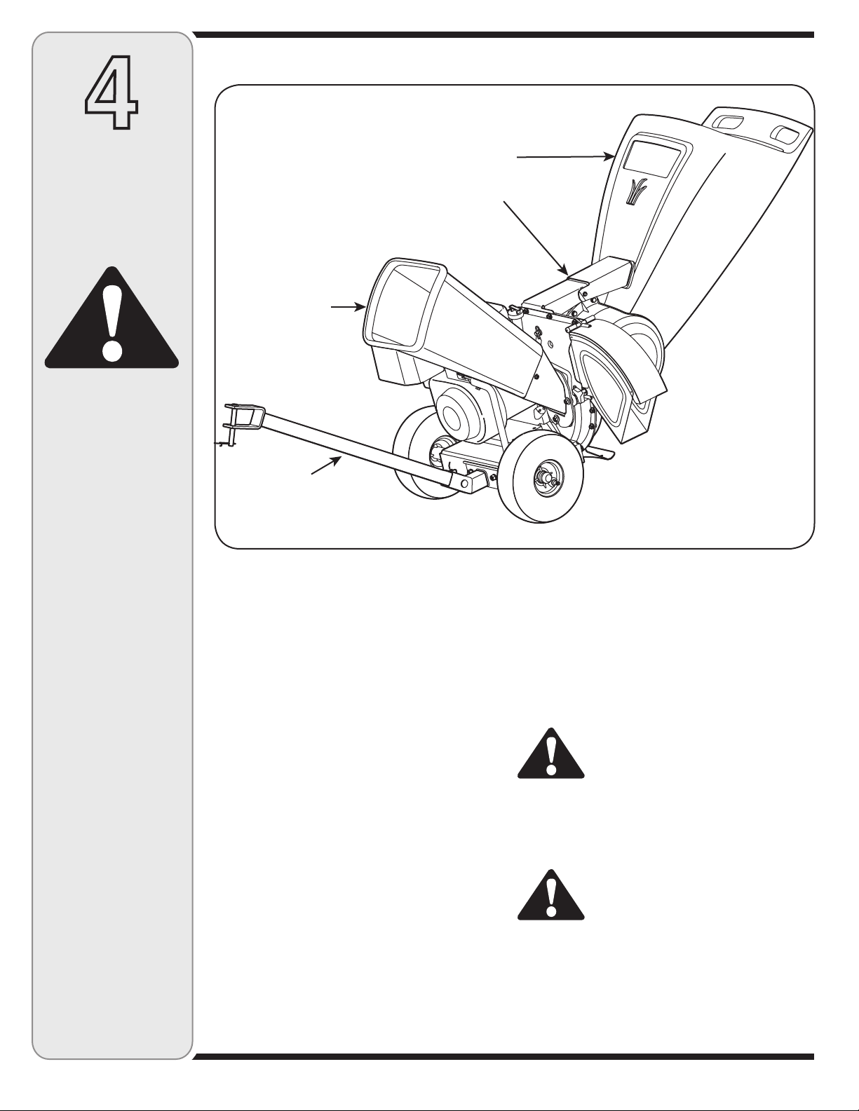
Know Your Chipper Shredder
Hopper Assembly
Release Rod
Chipper Chute
Tow Bar†
*Model 464 Shown with Optional Tow Bar
Figure 4-1
Now that you have set up your chipper shredder for
operation, get aquainted with its controls and features.
These are described below and illustrated on this page.
This knowledge will allow you to use your new equipment to its fullest potential.
Chipper Chute
Allows twigs and small branches up to 3” (2” for Model
Series 450) in diameter to be fed into the impeller for
chipping. See Figure 4-1.
Hopper Assembly
Allow leaves and small branches up to 1/2 diameter
to be fed into the impeller for chipping and shredding.
Material can be raked into hopper assembly by lowering
the hopper assembly. See Figure 4-1.
Release Rod
The release rod is located on the impeller bracket
assembly and it is used to release or lock the hopper
when raising or lowering. See Figure 4-1.
Tow Bar (If Equipped)
Use the tow bar to tow the chipper shredder behind a
tractor to a job site. See Figure 4-1.
NOTE: If your unit is not equipped with a tow bar, you
may contact Customer Support as instructed on page 2
for information regarding price and availability.
† If Equipped
Gas and Oil Fill-Up
1. Check oil level and add oil if necessary. Follow engine
manual for this. See Engine Manual for location of the
oil fill.
2. Service the engine with gasoline as instructed in the
engine manual. See Engine Manual for location of
gas fill.
WARNING: Use extreme care when handling gasoline. Gasoline is extremely
flammable and the vapors are explosive.
Never fuel the machine indoors or while
the engine is hot or running. Extinguish
cigarettes, cigars, pipes and other
sources of ignition.
WARNING: The operation of any
chipper shredder can result in foreign
objects being thrown into the eyes,
which can damage your eyes severely. Always wear the safety glasses
provided with this unit or eye shields
before chipping or shredding and while
performing any adjustments or repairs.
10
Page 11
This Operators Manual covers a range of product
specifications for various models. Characteristics and features discussed and /or illustrated in this manual may not
be applicable to all models. MTD LLC reserves the right
to change product specifications, designs and equipment
without notice and without incurring obligation.
STOP
4
Starting Engine
WARNING: Never run the engine
indoors or in a poorly ventilated area.
Engine exhaust contains carbon monoxide, an odorless and deadly gas.
IMPORTANT: Because this manual covers several
different model units, different starting instructions may
apply to your particular engine. Some engines may have
a fuel petcock, some may not. Some engines may have
On/Off switches, other may not. Some units will utilize a
choke system, while others will require priming. These
factors depend on what make and model engine comes
with your particular unit. For these reasons, please refer
to the engine operator’s manual for the correct starting
procedure.
1. Attach spark plug wire to spark plug. Make certain
the metal cap on the end of the spark plug is fastened
securely over the metal tip on the spark plug.
2. Engines with choke lever:
Move choke lever on engine to CHOKE position. (A
warm engine may not require choking).
Engines with primer:
Prime engine as instructed in separate engine manual.
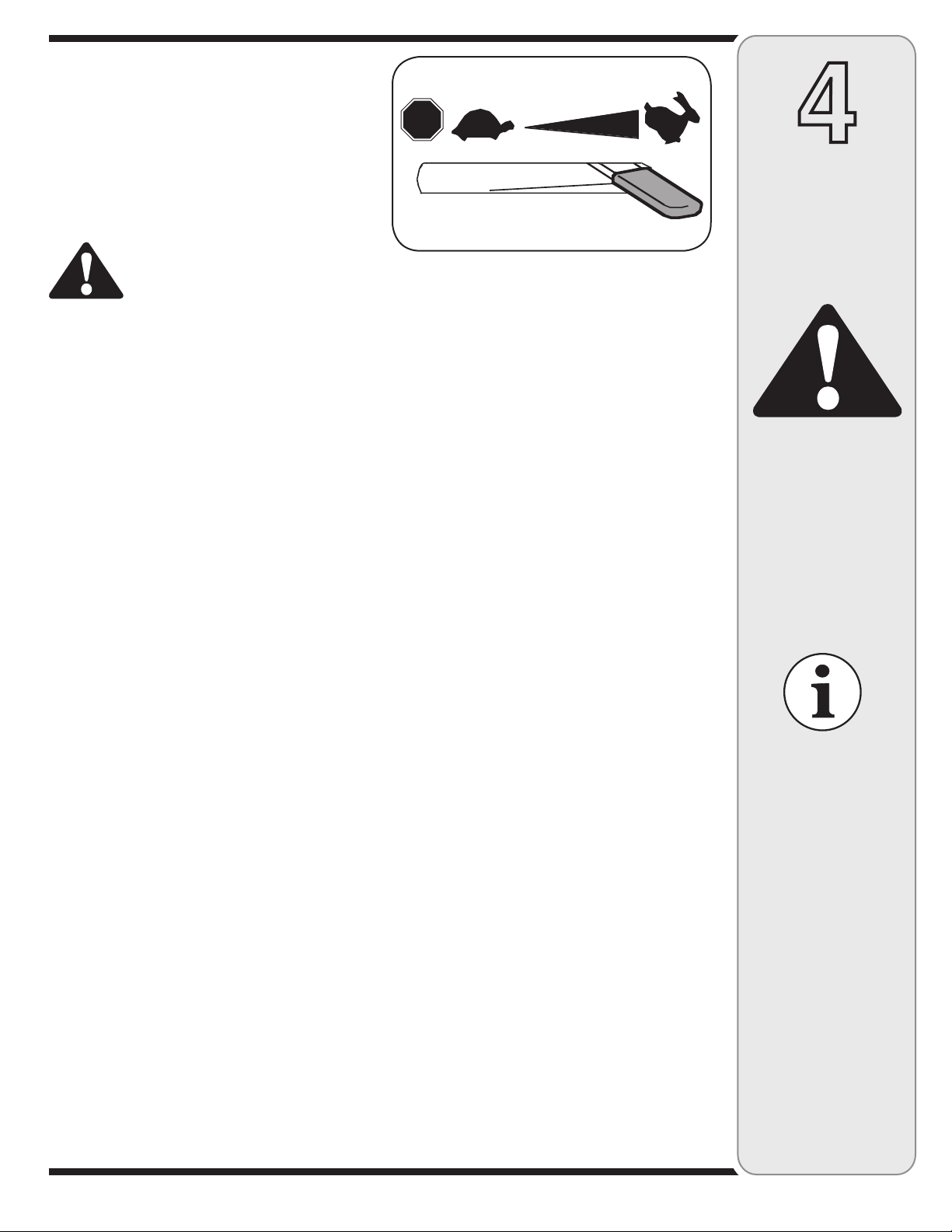
3. The throttle control lever is located on the engine.
Move engine throttle control lever to FAST or START
position. See Figure 4-2.
4. Grasp starter handle and pull rope out slowly until
engine reaches start of compression cycle (rope will
pull slightly harder at this point).
NOTE: A noise will be heard when finding the start of
the compression cycle. This noise is caused by the flails
and fingers, which are part of the shredding mechanism,
and it should be expected until the impeller reaches full
speed.
Figure 4-2
Stopping Engine
1. Move throttle control lever to STOP or OFF position.
2. Disconnect spark plug wire from spark plug and
ground against the engine.
NOTE: See your engine manual packed with your unit
for more detailed instructions.
Using The Chipper Shredder
Yard waste such as leaves and pine needles can be
raked up through the hopper assembly for shredding.
After material has been shredded by the flail blades
on the impeller assembly, it will be discharged out of
opening or into catcher bag. Do not attempt to shred
or chip any material other than vegetation found in a
normal yard (i.e. branches, leaves, twigs, etc.) Avoid
fibrous plants such as tomato vines until they are
thoroughly dried out. Twigs and small branches up to 3”
(2” for Model Series 450) in diameter can be fed into
the chipper chute.
Lowering The Hopper Assembly
1. With one hand grasp the handle at the top of the
hopper assembly and lift slightly.
2. With the other hand pull out on the release rod
and lower the hopper assembly to the ground. See
Figure 4-1.
To Empty Bag
1. Un-clip drawstring and loosen bag from chute
deflector opening.
2. Empty bag and reattach to the discharge chute
opening. Pull on the drawstring until the bag is tight
around the chute opening and clip the drawstring
tight against the chute deflector.
Operating
Your Chipper
Shredder
WARNING
Never run the engine
indoors or in a poorly
ventilated area. Engine
exhaust contains
carbon monoxide, an
odorless and deadly
gas.
NOTE: A noise will be
heard when finding the start
of the compression cycle.
This noise is caused by
the flails and fingers, which
are part of the shredding
mechanism, and it should
be expected until the impeller reaches full speed.
5. Pull rope with a rapid, continuous, full arm stroke.
Keep a firm grip on starter handle. Let rope rewind
slowly.
6. Repeat the previous steps until engine fires. When
engine starts, move choke control (if equipped)
gradually to RUN position.
IMPORTANT: The flail screen is located inside the
housing in the discharge area. If the flail screen
becomes clogged, remove and clean as instructed in
SECTION 5: MAINTAINING YOUR CHIPPER SHREDDER. For best performance, it is also important to keep
the chipper blade sharp.
11
Page 12
5
Maintaining
Your Chipper
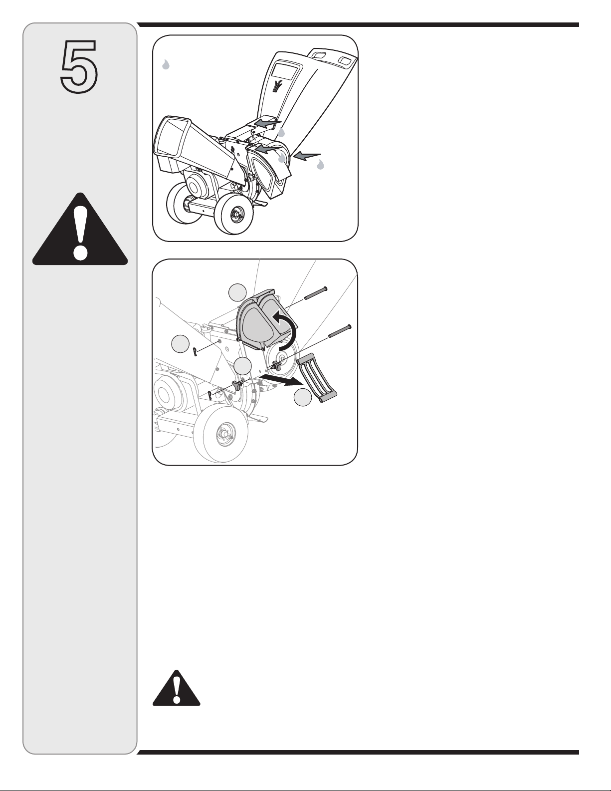
Lubricate these
points before
reassembly.
Lubrication
1. Lubricate the release rod and spring with light oil once
a season. See Figure 5-1.
2. Lubricate the pivot points on the hopper assembly with
light oil once a season. See Figure 5-1.
3. Lubricate the pivot points on the discharge chute with
light oil once a season. See Figure 5-1.
4. Follow the accompanying engine manual for lubrica
tion schedule and instruction for engine lubrication.
-
Shredder
WARNING
Always stop engine,
disconnect spark
plug, and ground
against engine
before cleaning,
lubricating or
doing any kind of
maintenance on your
machine.
*Model 464 Shown
Figure 5-1
B
C
A
D
*Model 464 Shown
Figure 5-2
General Recommendations
1. Always observe safety rules when performing
any maintenance.
2. The warranty on this chipper shredder does not
cover items that have been subjected to operator
abuse or negligence. To receive full value from warranty, operator must maintain the chipper shredder
as instructed here.
3. Changing of engine-governed speed will void
engine warranty.
4. All adjustments should be checked at least once
each season.
5. Periodically check all fasteners and make sure these
are tight.
WARNING: Always stop engine,
disconnect spark plug, and ground
against engine before cleaning,
lubricating or doing any kind of
maintenance on your machine.
Engine Care
1. Maintain oil level as instructed in engine manual.
2. Service air cleaner every 25 hours under normal
conditions. Clean every few hours under extremely
dusty conditions. Refer to engine manual.
3. Clean spark plug and reset the gap once a season.
Check engine manual for correct plug type and gap
specifications.
4. Clean engine regularly with a cloth or brush. Keep the
cooling system (blower housing area) clean to permit
proper air circulation. Remove all grass, dirt and
combustible debris from muffler area.
Removing The Flail Screen
If the discharge area becomes clogged, remove the flail
screen and clean area as follows:
1. Stop the engine and make certain the chipper shredder has come to a complete stop.
2. Disconnect spark plug wire from spark plug and
ground against the engine.
3. a. Remove the bag and two wing knobs on each side
of the chute deflector. See Figure 5-2.
b. Lift the chute deflector up to keep it out of the way.
c. Remove the two hairpin clips from each clevis pin
which extend through the housing and remove pins.
d. Remove the flail screen from inside the housing
and clean the screen by scraping or washing with
water. See Figure 5-2.
4. Reinstall the screen, making certain to reassemble the
flail screen with the curve side down.
5. Reattach the chute deflector with the hardware
previously removed and connect the bag to unit.
Sharpening Or Replacing Chipper
Blades
1. Disconnect the spark plug wire and ground against the
engine.
2. Remove the flail screen as instructed in the previous
section.
3. Remove the chipper chute by removing three hex nuts
and washers.
4. Remove the chipper chute support brace (Model
Series 460) from the frame by removing the hex bolts.
5. Rotate impeller assembly by hand until you locate one
of two chipper blades in the chipper chute opening.
12
Page 13
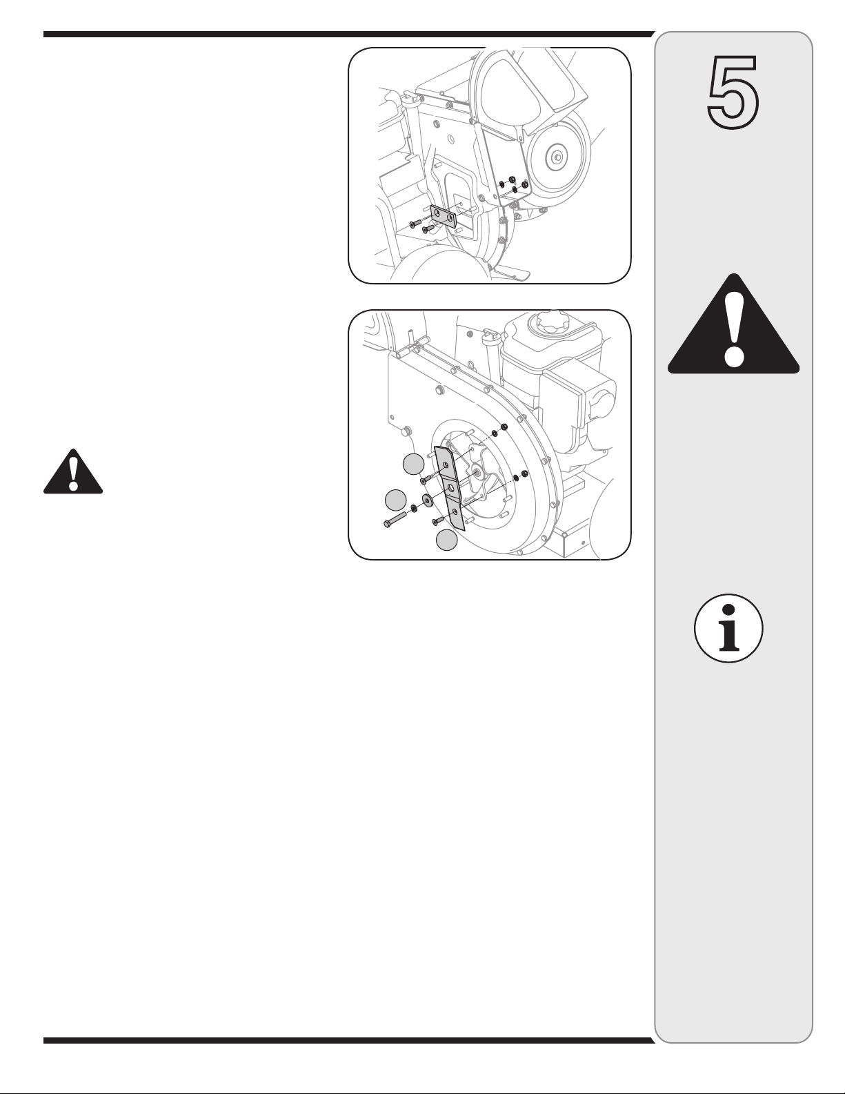
6. Remove the blade by removing the internal hex
screws, lock washers, and hex nuts which secure it to
the impeller. Retain the hardware. See Figure 5-3.
NOTE: Use a 3 /16” hex key (Allen) wrench on the outside
of the blade and a 1/2” box (or socket) wrench on the
inside of the impeller. Hold the Allen wrench stationary
and rotate the box (or socket) wrench to loosen the nut.
7. Install a replacement blade (Part No. 781-0490) with
the hardware removed earlier or sharpen.
IMPORTANT: When sharpening the blade, protect hands
by using gloves. Follow the original angle of grind and
make sure to remove an equal amount from each blade.
8. To replace the other blade, rotate the impeller to
expose the second blade and repeat the steps above.
NOTE: Make certain blades are reassembled with the
sharp edge facing upward. Torque hardware to 250 - 300
in. lbs.
WARNING: The impeller’s chipper
blades and shredder blade are sharp.
Wear leather work gloves to protect your
hands.
Sharpening Or Replacing The Shred-
der Blade
1. Stop the engine and make certain that all moving
parts have come to a complete stop.
2. Disconnect the spark plug wire and ground against the
engine.
3. Lower the hopper assembly and block up the housing.
4. Remove the six hex lock nuts and flat washers
from the weld studs on the flail housing. Retain the
hardware.
5. Carefully separate the hopper assembly from the
impeller assembly and remove the support plate.
NOTE: When reassembling the support plate, make
certain the embossed tab faces inward towards the
impeller.
6. Remove the two wing knobs and cupped washers that
secure the chute deflector and raise the chute.
7. Insert a 1/2” or 3/4” diameter pipe through the flail
screen into the impeller to keep it from turning or
remove the flail screen and insert a piece of wood into
the chute opening.
8. a. Remove the two internal hex screws, lock washers,
and hex lock nuts which secure the shredder blade
to the impeller.
b. Remove the hex bolt, lock washer, and flat washer
to completely free shredder blade. See Figure 5-4.
Figure 5-3
A
B
A
Figure 5-4
NOTE: Use a 3 /16” hex key (Allen) wrench on the
outside of the shredder blade and a 1/2” box (or socket)
wrench on the inside of the shredder blade. Hold the
Allen wrench stationary and rotate the box (or socket)
wrench to loosen the nut. Use caution when removing
the blade to avoid contacting the weld studs on housing.
IMPORTANT: When sharpening the blade, follow
the original angle of grind as a guide. It is extremely
important that each cutting edge receives an equal
amount of grinding to prevent an unbalanced blade.
An unbalanced blade will cause excessive vibration
when rotating at high speeds and may cause damage
to the unit. The blade can be tested by balancing it on a
screwdriver or nail. Remove metal from the heavy side
until it is balanced evenly.
Storing Your Chipper Shredder
The following steps should be taken to prepare your
chipper shredder for storage.
1. Clean the equipment thoroughly.
2. Wipe equipment with an oiled rag to prevent rust.
3. Refer to engine manual for correct engine storage
instructions.
4. Store unit in a clean, dry area. Do not store next to
corrosive materials such as fertilizer.
5
Maintaining
Your Chipper
Shredder
WARNING
The impeller’s
chipper blades and
shredder blade are
sharp. Wear leather
work gloves to
protect your hands.
IMPORTANT
Make certain chipper
blades are reassembled with the sharp
edge facing upward.
Torque hardware to
250 - 300 in. lbs.
IMPORTANT
When reassembling the
shredder blade, tighten
center bolt to between
550 and 700 in.-lbs.
and the two out bolts to
between 250 and 350
in.-lbs.
13
Page 14
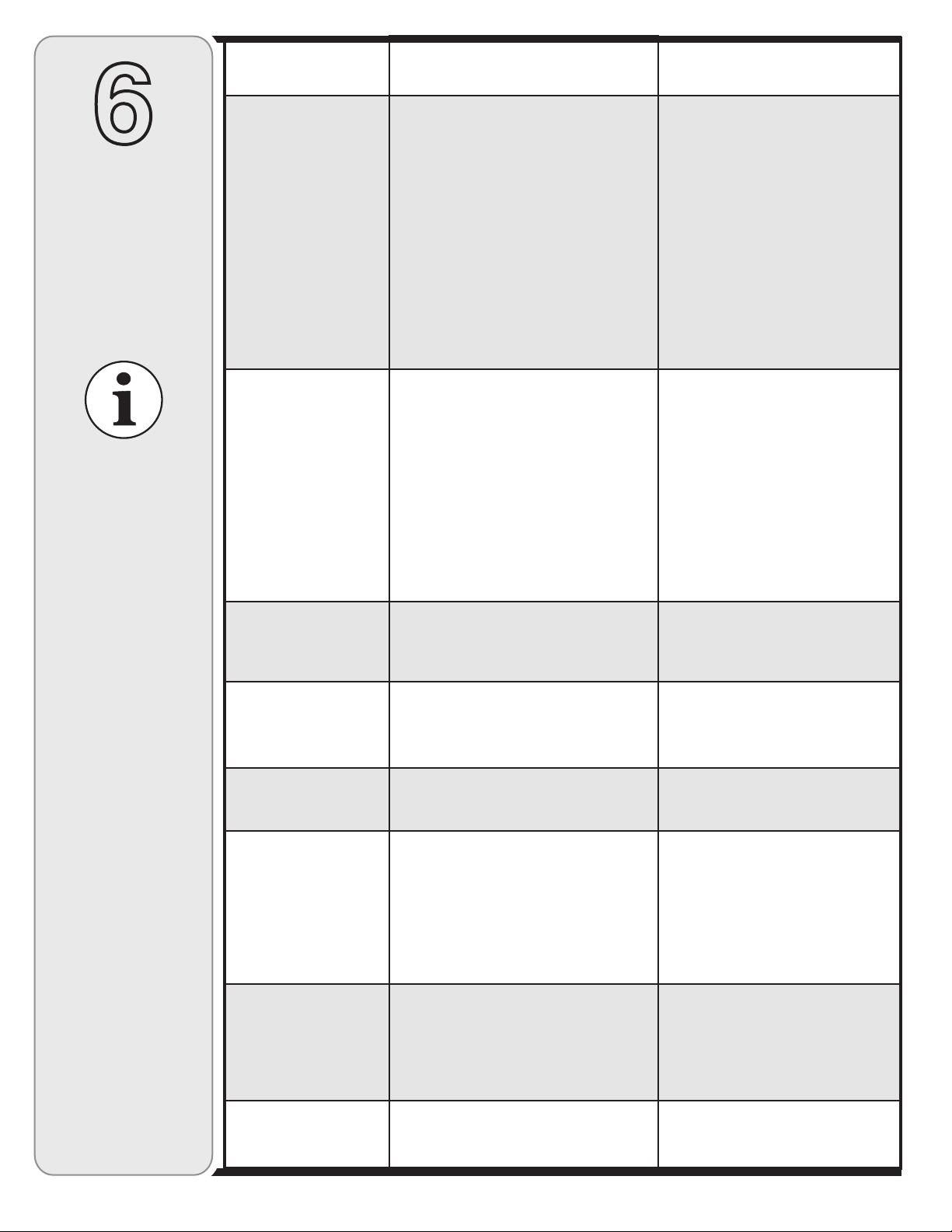
CauseProblem Remedy
6
Trouble
Shooting
For repairs beyond
the minor adjustments
listed here, contact
an authorized service
dealer.
Engine fails to start
Engine runs erratic
1. Throttle lever not in correct starting
position (if equipped).
2. Spark plug wire disconnected.
3. Choke not in CHOKE position (if
equipped).
4. Fuel tank empty or stale fuel.
5. Engine not primed (if equipped).
6. Faulty spark plug.
7. Blocked fuel line.
8. Engine flooded.
1. Spark plug wire loose.
2. Unit running on CHOKE (if equipped).
3. Blocked fuel line or stale fuel.
4. Vent in gas cap plugged.
5. Water or dirt in fuel system.
6. Dirty air cleaner.
7. Carburetor out of adjustment.
1. Move throttle lever to FAST or
START position.
2. Connect wire to spark plug.
3. Move choke lever to CHOKE
position.
4. Fill tank with clean, fresh gasoline.
5. Prime engine as instructed in
Engine Manual.
6. Clean, adjust gap, or replace.
7. Clean fuel line.
8. Wait a few minutes to restart, but
do not prime.
1. Connect and tighten spark
plug wire.
2. Move choke lever to OFF position.
3. Clean fuel line; fill tank with clean,
fresh gasoline.
4. Clear vent.
5. Drain fuel tank. Refill with
fresh fuel.
6. Refer to engine manual.
7. See authorized service dealer.
Engine overheats
Occasional skips
(hesitates) at
high speed
Excessive
Vibration
Unit does not
discharge
Rate of discharge
slows considerably
or composition of
discharged material
changes
1. Engine oil level low.
2. Dirty air cleaner.
3. Carburetor not adjusted properly.
1. Spark plug gap too close.
2. Carburetor idle mixture adjustment
improperly set.
1. Loose parts or damaged impeller.
1. Chute deflector clogged.
2. Foreign object lodged in impeller.
3. Low engine RPM.
1. Low engine RPM.
2. Chipper blade dull.
1. Fill crankcase with proper oil.
2. Refer to engine manual.
3. See authorized service dealer.
1. Adjust gap to .030”.
2. See authorized service dealer.
1. See authorized service dealer.
1. Stop engine immediately and
disconnect spark plug wire. Clean
flail screen and inside of discharge
opening.
2. Stop engine and disconnect spark
plug wire. Remove lodged object.
3. Always run engine at full throttle.
1. Always run engine at full throttle.
2. Replace chipper blade or see your
authorized service dealer.
14
Page 15

NOTES
Use this page to make notes and write down important information.
15
Page 16
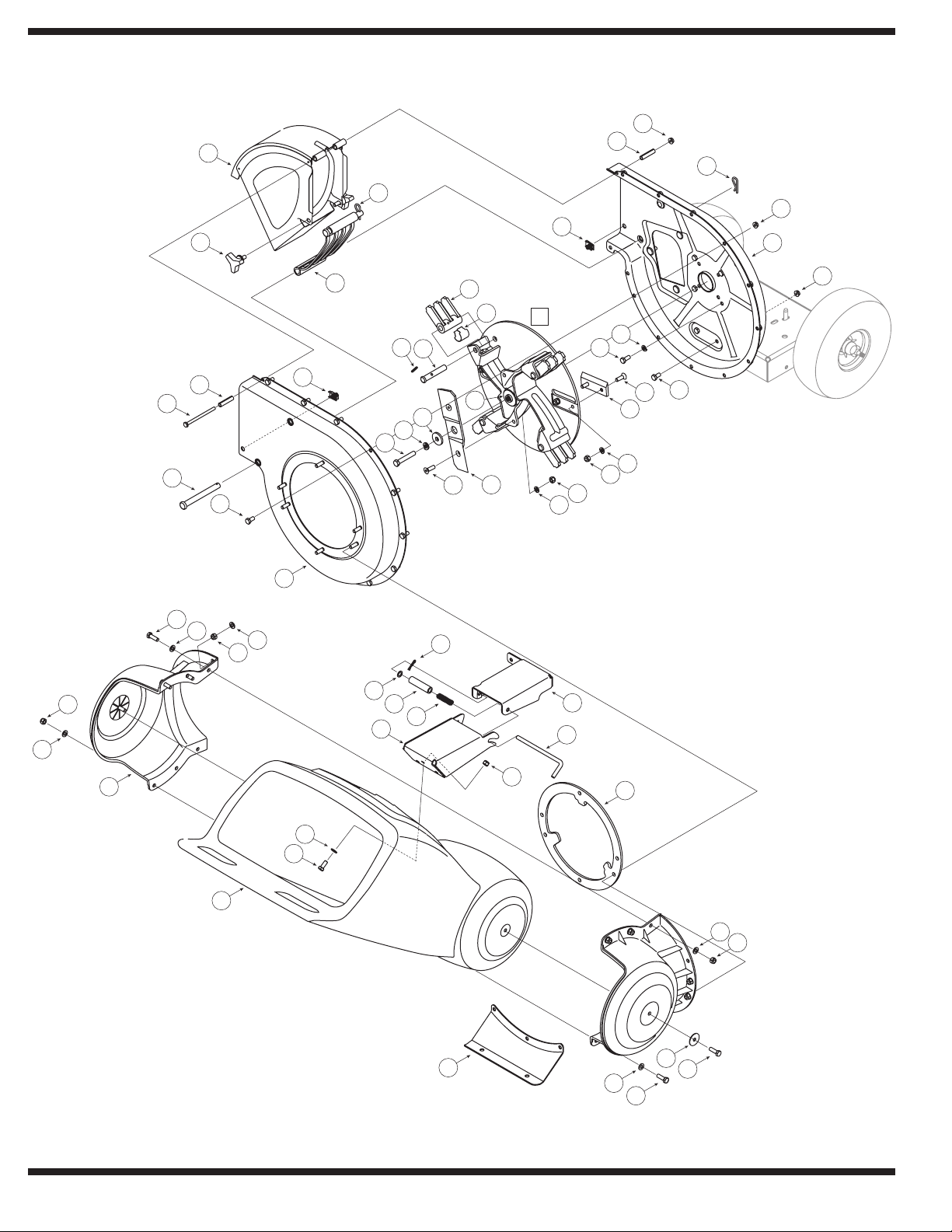
Model Series 450 and 460
4
9
8
2
27
5
35
34
2
7
3
6
22
8
13
34
38
7
1
25
26
21
23
33
16
20
23
19
24
17
11
18
14
18
11
11
15
16
13
10
12
10
34
38
39
42
43
34
32
40
36
31
28
38
41
30
34
29
35
37
35
34
38
16
Page 17
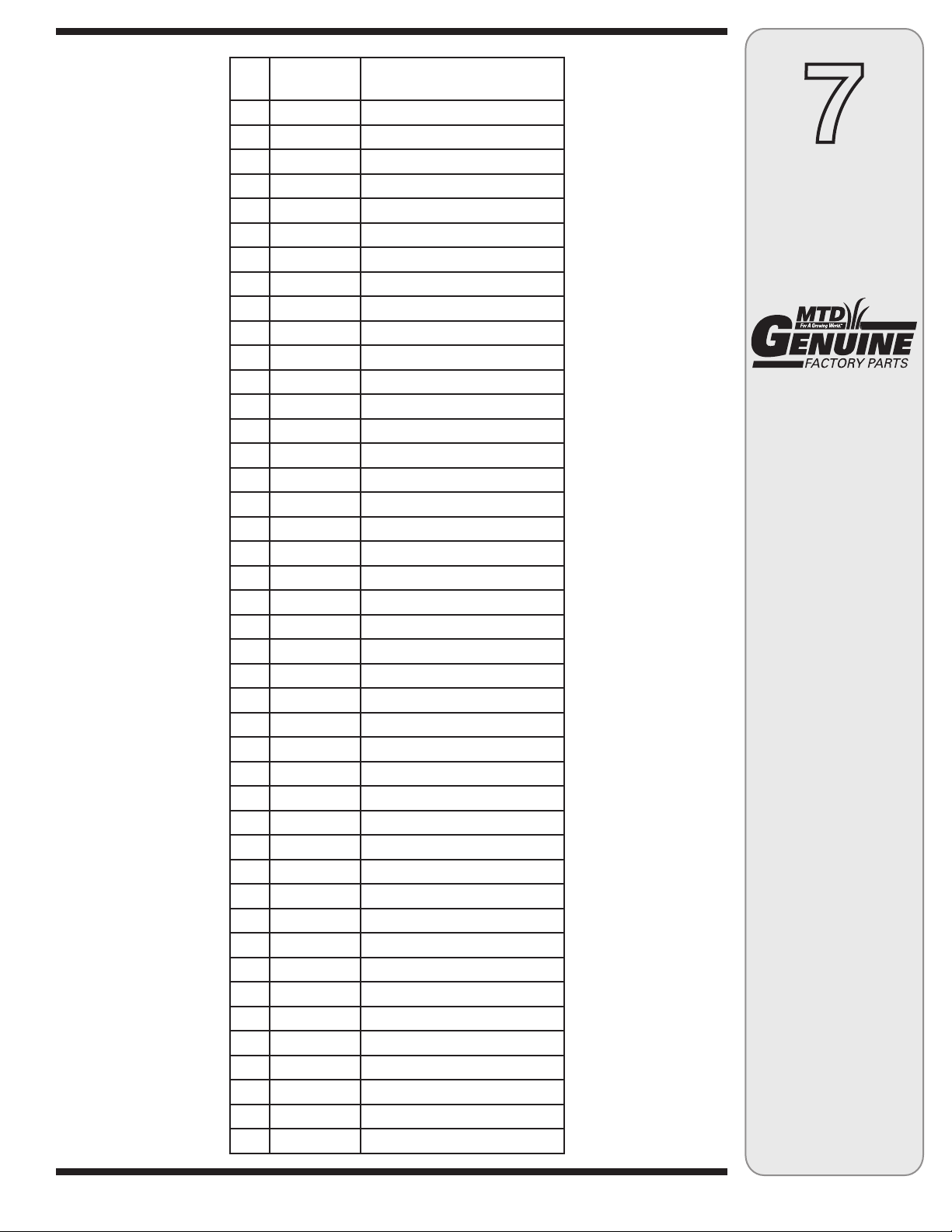
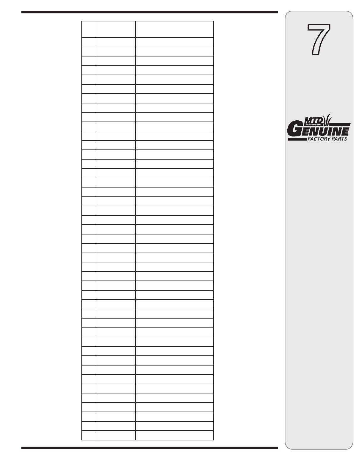
Ref.
No.
1. 736-0217 Lock Washer, 3/8
2. 714-0149B Cotter Pin
3. 681-0048 Wing Knob 5/16-18
4. 681-0094 Chute Deflector Assembly
5. 711-0835 Clevis Pin
6. 781-0457 Shredder Screen
8. 750-0793 Spacer
9. 712-3027 Hex Lock Nut, 1/4-20
10. 712-3004A Hex Lock Nut 5/16-18
11. 736-0119 Lock Washer 5/16
12. 681-0117 Inner Impeller Housing Assembly
13. 710-3025 Hex Cap Screw 5/16-18 x.625
14. 710-0157 Hex Cap Screw 5/16-24 x.75
15. 781-0490 Chipper Blade
16. 710-1054 Hex Cap Screw 5/16-24 x 1.0
17. 681-0030 Impeller Assembly
18. 712-0411 Hex Lock Nut 5/16-24
19. 781-0735 Retainer Pin Clip
20. 719-0329 Flail Blade
21. 711-0833B Clevis Pin
22. 715-0166 Pin
23. 736-0247 Flat Washer 3/8 x 1.25
24. 742-0571 Shredder Blade
25. 710-1254 Hex Cap Screw 3/8-24 x 2.25
26. 681-0004A Outer Impeller Housing Assembly
27. 710-0825 Hex Cap Screw 1/4-20 x 3.75
28. 781-0515 Front Support Bracket
29. 781-0574 Shredder Plate
30. 681-0104 Rear Hopper Bracket Assembly
31. 732-0306 Compression Spring 1.75
32. 736-0117 Flat Washer
33. 714-0104 Cotter Pin
34. 736-0264 Flat Washer.330 ID x.630 OD
35. 710-0376 Hex Cap Screw 5/16-18 x 1.0
36. 748-0453 Spacer,.375 ID x 2.50 LG
37. 736-0362 Flat Washer.320 ID x 1.25 OD
38. 712-0429 Hex Lock Nut 5/16-18
39. 731-1710A Hopper Collar
40. 681-0123 Front Hopper Bracket Assembly
41. 711-1128 Lock Rod
42. 731-1707 Hopper Assembly
43. 710-3008 Hex Cap Screw 5/16-18 x.75
Part No. Description
7. 726-0211 U-Nut 5/16-18
7
Parts List
To order replacement
parts, contact
1-800-800-7310 or visit
www.mtdproducts.com
NOTE: This Operators
Manual covers a range
of product specifications for various
models. Characteristics
and features discussed
and/or illustrated in this
manual may not be applicable to all models.
MTD LLC reserves the
right to change product
specifications, designs
and equipment without
notice and without
incurring obligation.
17
Page 18
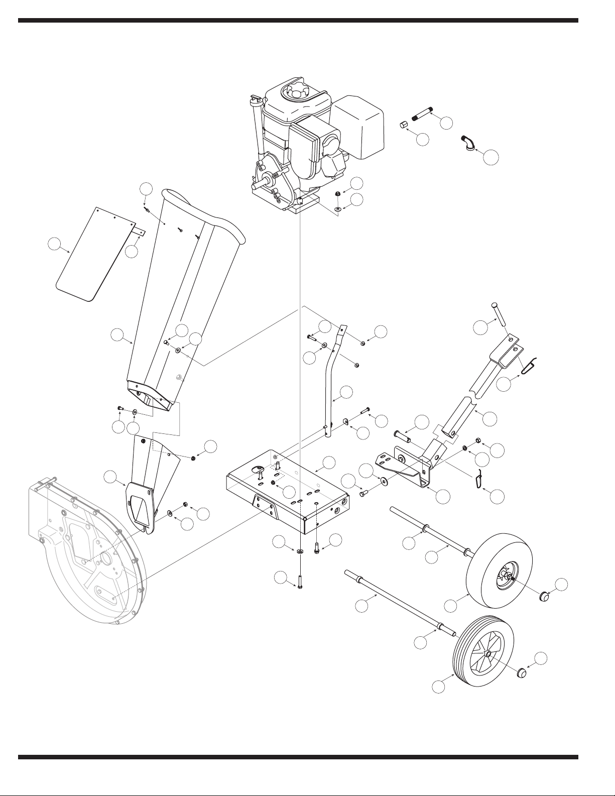
Model Series 450 and 460
25
26
24
21
12
29
13
10
22
34
7
8
30
28 33
31
33
27
32
35
1
3
4
2
6
9
5
6
9
7
7
8
9
10
11
15
14
18
23
17
16
17
20
19
18
20
19
Page 19
Ref.
No.
1. 728-0175†† Pop Rivet
2. 681-0095† Chipper Shredder Chute
3. 735-0249†† Chute Flap
4. 781-0633†† Chute Flap Strip
5. 681-0068A†† Chipper Chute Assembly
6. 710-0751†† Hex Cap Screw 1/4 -20 x.620
7. 712-3027†† Hex Lock Nut 1/4-20
8. 710-0106†† Hex Cap Screw 1/4-20 x 1.25
9. 736-0173†† Flat Washer.28 ID x.74 OD
10. 736-0242 Bell Washer.340 ID x.872 OD
11. 712-3010 Hex Nut 5/16-18
12. 749-1004†† Support Brace
13. 712-3004A Hex Lock Nut 5/16-18
14. 710-0805† Hex Cap Screw 5/16-18 x 1.50
15. 736-0170 Bell Washer 5/16 x 1.0
16. 736-0366†† Flat Washer
17. 738-0814† Axle Assembly
18. 750-0786† Spacer
19. 734-1600† Wheel Comp., 10.0 x 2.5 Plastic
20. 726-0214 Push Cap
21. 681-0184A† Frame
22. 736-0451†† Washer,.320 ID x.93 OD
23. 710-0502A Screw, 3/8-16 x 1.250
24. 737-0195† Elbow Fitting
25. 737-0298†† Oil Drain Pipe
26. 737-0132†† Oil Drain End Cap
27. 681-0133* Tongue Hitch Mount
28. 681-0134A* Base Hitch Mount
29. 710-3001* Hex Cap Screw, 3/8-16 x.88
30. 711-0299* Clevis Pin,.625 x 2.4
31. 711-0835* Clevis Pin,.50 x 4.62
32. 712-04065* Flange Lock Nut, 3 /8-16
33. 732-0194* Spring Pin
34. 736-0133* Flat Washer,.411 x 1.25 x 1.0
35. 736-0169* Lock Washer, 3/ 8
— 723-0400 Safety Glasses (Not Shown)
— 664-04022† Chipper Bag Ass’y (Not Shown)
— 664-04023†† Chipper Bag Ass’y ( Not Shown)
Part No. Description
731-1899†† Chipper Shredder Chute
710-3180†† Hex Cap Screw 5/16-18 x 1.75
738-0813†† Axle Assembly
734-1845†† Wheel Complete, 10.0 x 4.0 Gray
681-0183A†† Frame
7
Parts List
To order replacement
parts, contact
1-800-800-7310 or visit
www.mtdproducts.com
NOTE: This Operators
Manual covers a range
of product specifications for various
models. Characteristics
and features discussed
and/or illustrated in this
manual may not be applicable to all models.
MTD LLC reserves the
right to change product
specifications, designs
and equipment without
notice and without
incurring obligation.
† Model Series 450
†† Model Series 460
* If Equipped
19
Page 20

MANUFACTURER’S LIMITED WARRANTY FOR
The limited warranty set forth below is given by MTD LLC with
respect to new merchandise purchased and used in the United States
and/or its territories and possessions, and by MTD Products Limited
with respect to new merchandise purchased and used in Canada and/
or its territories and possessions (either entity respectively, “MTD”).
“MTD” warrants this product (excluding its Normal Wear Parts and
Attachments as described below) against defects in material and
workmanship for a period of two (2) years commencing on the date
of original purchase and will, at its option, repair or replace, free of
charge, any part found to be defective in materials or workmanship.
This limited warranty shall only apply if this product has been
operated and maintained in accordance with the Operator’s Manual
furnished with the product, and has not been subject to misuse,
abuse, commercial use, neglect, accident, improper maintenance,
alteration, vandalism, theft, fire, water, or damage because of other
peril or natural disaster. Damage resulting from the installation or use
of any part, accessory or attachment not approved by MTD for use
with the product(s) covered by this manual will void your warranty as
to any resulting damage.
Normal Wear Parts are warranted to be free from defects in material
and workmanship for a period of thir ty (30) days from the date of
purchase. Normal wear parts include, but are not limited to items
such as: batteries, belts, blades, blade adapters, tines, grass bags,
wheels, rider deck wheels, seats, snow thrower skid shoes, friction
wheels, shave plates, auger spiral rubber and tires.
Attachments — MTD warrants attachments for this product against
defects in material and workmanship for a period of one (1) year,
commencing on the date of the attachment’s original purchase or
lease. Attachments include, but are not limited to items such as:
grass collectors and mulch kits.
HOW TO OBTAIN SERVICE: Warranty service is available, WITH
PROOF OF PURCHASE, through your local authorized service dealer.
To locate the dealer in your area:
In the U.S.A.
Check your Yellow Pages, or contact
Cleveland, Ohio 44136-0019, or call 1-800-800-7310, 1-330-2204683 or log on to our Web site at www.mtdproducts.com
In Canada
Contact MTD Products Limited, Kitchener, ON N2G 4J1, or call 1-800668-1238 or log on to our Web site at www.mtdcanada.com.
This limited warranty does not provide coverage in the following
cases:
a. The engine or component parts thereof. These items may carry a
separate manufacturer’s warranty. Refer to applicable manufacturer’s warranty for terms and conditions.
b. Log splitter pumps, valves, and cylinders have a separate one-
year warranty.
MTD LLC at P.O. Box 361131,
.
c. Routine maintenance items such as lubricants, filters, blade
sharpening, tune-ups, brake adjustments, clutch adjustments,
deck adjustments, and normal deterioration of the exterior finish
due to use or exposure.
d. Service completed by someone other than an authorized service
dealer.
e. MTD does not extend any warranty for products sold or exported
outside of the United States and/or Canada, and their respective
possessions and territories, except those sold through MTD’s
authorized channels of export distribution.
f. Replacement parts that are not genuine MTD parts.
g. Transportation charges and service calls.
h. MTD does not warrant this product for commercial use.
No implied warranty, including any implied warrant y of
merchantability of fitness for a particular purpose, applies after
the applicable period of express written warranty above as to the
parts as identified. No other express warranty, whether written or
oral, except as mentioned above, given by any person or entity,
including a dealer or retailer, with respect to any product, shall
bind MTD. During the period of the warranty, the exclusive remedy
is repair or replacement of the product as set forth above.
The provisions as set forth in this warranty provide the sole and
exclusive remedy arising from the sale. MTD shall not be liable
for incidental or consequential loss or damage including, without
limitation, expenses incurred for substitute or replacement lawn
care services or for rental expenses to temporarily replace a
warranted product.
Some states do not allow the exclusion or limitation of incidental
or consequential damages, or limitations on how long an implied
warranty lasts, so the above exclusions or limitations may not apply
to you.
In no event shall recovery of any kind be greater than the amount of
the purchase price of the product sold. Alteration of safety features of
the product shall void this warranty. You assume the risk and liability
for loss, damage, or injury to you and your property and/or to others
and their property arising out of the misuse or inability to use the
product.
This limited warranty shall not extend to anyone other than the
original purchaser or to the person for whom it was purchased as a
gift.
HOW STATE LAW RELATES TO THIS WARRANTY: This limited
warranty gives you specific legal rights, and you may also have other
rights which vary from state to state.
IMPORTANT: Owner must present Original Proof of Purchase to
obtain warranty coverage.
MTD LLC, P.O. BOX 361131 CLEVELAND, OHIO 44136-0019; Phone: 1-800-800-7310, 1-330-220-4683
MTD Canada Limited - KITCHENER, ON N2G 4J1; Phone 1-800-668-1238
GDOC-100015 REV. B
Page 21
Seguridad•Ensamblaje•Operación•Consejos y Técnicas•Mantenimiento•Solución de problemas•Lista de Parte•Grantías
MANUAL DEL OPERADOR
*Modelo Serie 460
Cortadora Trituradora - Modelo Serie 450 y 460
IMPORTANTE
LEA CON ATENCIÓN LAS REGLAS DE SEGURIDAD E INSTRUCCIONES ANTES
DE OPERAR LA ASPIRADORA PARA PATIOS CON PROPULSIÒN
ADVERTENCIA: Esta unidad está equipada con un motor de combustión interna y no debe ser utilizada en o cerca de un
terreno agreste cubierto por bosque, malezas o hierba excepto que el sistema de escape del motor esté equipado con un
amortiguador de chispas que cumpla con las leyes locales o estatales correspondientes (en caso de existir). Si se utiliza
un amortiguador de chispas el operador lo debe mantener en condiciones de uso adecuadas. En el Estado de California
las medidas anteriormente mencionadas son exigidas por ley (Artículo 4442 del Código de Recursos Públicos de Califor
nia). Es posible que existan leyes similares en otros estados. Las leyes federales se aplican en territorios federales. Su
distribuidor más cercano autorizado para realizar el mantenimiento del motor puede conseguir el amortiguador de chispas
para el silenciador sino usted puede comunicarse con el departamento de servicios al apartado postal P.O. Box 361131
Cleveland, Ohio 44136-0019.
PRINTED IN U.S.A
MTD LLC, P.O. BOX 361131 CLEVELAND, OHIO 44136-0019
-
Page 22
Este manual de operador es una parte importante de su nueva máquina cortadora trituradora. Le
ayudará a montar, preparar y mantener la unidad para obtener los mejores resultados.
Por favor lea y comprenda el contenido del manual.
Índice
Etiquetas de seguridad .................................... 23
Prácticas de seguridad en la operación ......... 24
Configuración de la cortadora trituradora ..... 26
Funcionamiento de la cortadora trituradora .. 30
Búsqueda y registro del número de modelo
ANTES DE COMENZAR A ENSAMBLAR SU NUEVO
EQUIPO,
por favor localice la placa del modelo en el equipo y copie la
información en la placa modelo a la derecha. Para encontrar
la placa de modelo colóquese detrás de la unidad en la
posición del operador y mire hacia abajo en la parte posterior
de la cubierta. La presente información resultará necesaria
para el uso del sitio web del fabricante y / o para solicitar
ayuda del Departamento de Asistencia al Cliente o de un
distribuidor autorizado.
Mantenimiento de la cortadora trituradora .... 32
Solución de problemas .................................... 34
Lista de las piezas ............................................ 16
Garantía ............................................................. 36
Número de modelo
Número de serie
Asistencia al Cliente
Por favor, NO devuelva la unidad al minorista a quien se la adquirió sin contactarse
primero con el Departamento de Asistencia al Cliente.
En caso de tener problemas para ensamblar este producto o de tener dudas con respecto a los controles, funcionamiento o
mantenimiento del mismo, puede solicitar la ayuda de los expertos. Elija entre las opciones que se presentan a continuación:
1. Visite mtdproducts.com.
2. Si desea contactarse con un Representante del Departamento de Asistencia al Cliente, por favor comuníquese al 1(800)
800-7310.
3. El fabricante del motor es el responsable de todas las cuestiones relacionadas con el rendimiento, potencia de salida,
especificaciones, garantía y mantenimiento del motor. Por favor, para mayor confirmación, consulte el manual del propietario/
operador del fabricante del motor que es enviado, en un paquete por separado, junto con su unidad.
22
Page 23
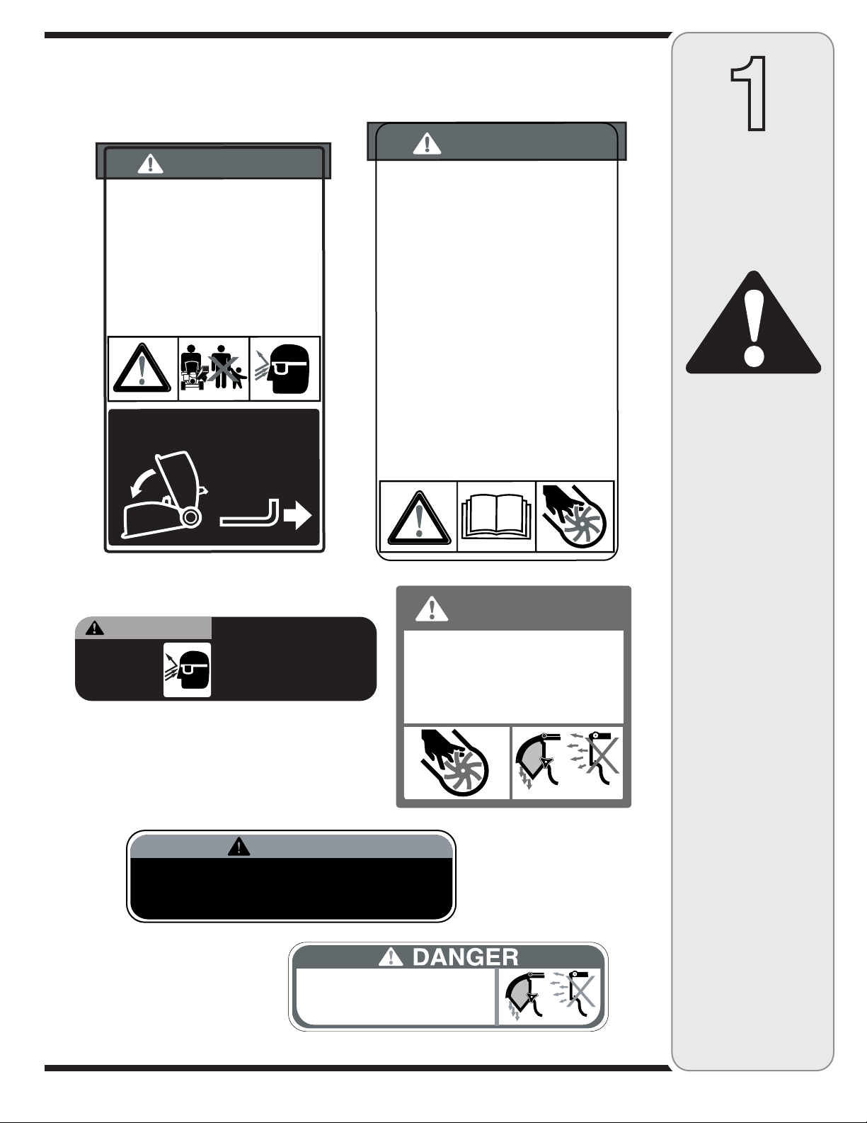
Etiquetas de Seguridad Encontradas En Su
DO NOT OPERATE THIS MACHINE
UNLESS THE CHUTE DEFLECTOR
HAS BEEN PROPERLY INSTALLED.
WARNING
• Do not transport machine while
engine is running.
• Shredder should not be towed on any
street, highway or public road.
• Do not tow shredder over 10 m.p.h.
• Do not allow anyone to sit or ride on
shredder.
• Do not tow shredder for long distances.
• Before towing, be certain the shredder
is correctly attached to towing vehicle.
S30228
DANGER
TO
AVOID SERIOUS INJU
RY
:
•
Read the
o
wner's ma
n
ual(s) be
f
ore star
ting and
using
unit.
• K
eep all shields and gua
r
ds in place and secure
ly
attached
.
• K
eep hands
,
f
eet
,
face,
clothing and long hair out of
Shredder Hoppe
r,
Chipper Chute and Dis
char
ge
C
hute while the engine is running
.
R
otating cutting
b
lades inside these openings will cause serious
per
sonal inju
ry if contacted
.
Material being
pr
ocessed
ma
y bounce ba
ck
fr
om inlet openings or be th
ro
wn
fr
om the dis
char
ge c
hut
e.
Long hair or loose
c
lothing
ma
y be pulled su
c
ked into the inlet openings
.
•
Do not place bran
c
hes o
ver 1/2 in
ch diameter into
the la
rg
e Shr
e
d
der Hoppe
r.
Bran
c
hes
o
ver 1/2 in
ch in
diameter should be placed in the Small Chipper
Chut
e.
•
If the
c
hipped shre
d
der jams or becomes
cl
ogged,
immediate
ly
shut off the engine and wait
f
or all
mo
ving par
ts to come to a complete stop be
f
ore
c
learing
.
•
Do not install re
m
ov
e,
adjust
,
or service the
dischar
ge screen or
a
ny
other pa
rt
while the engine
is running
.
Blade contact can occu
r.
DANGER
TO
AVOID SERIOUS INJU
RY
:
•
Do not operate on un
e
ven
g
r
ound where unit is
unstable
.
Do not operate on
p
a
vement
,
gra
vel or
other ha
rd
surfaces since objects can rico
c
het
and cause inju
ry
.
• T
o
av
oid a fire haza
rd
,
keep le
a
ves
,
grass
,
and other
comb
ustible materials
aw
ay
fr
om hot engine and
mu
ffle
r.
• K
eep
children and othe
rs
aw
ay
fr
om area of
operatio
n
.
• W
ear app
ro
ved safety glasses
,
glo
ves and ear
pr
otectio
n
.
INSTR
UCTIONS:
TO
RAISE AND
L
O
WER HOPPER
TO AVO I D
EY E I NJ U RY,
WE A R SA F TE Y
GL A SS ES .
DO NOT DEPOSIT
MATERIAL LARGER THAN
1/2" DIAMETER IN LARGE
SHREDDER HOPPER.
THIS MAY DAMAGE
MACHINE.
WA R N I N G
DANGER
• ROTATING CUTTING BLADES.KEEP H AN DS
AND FEET OUT OF OPENING WHILE
MACHINE IS RUN NIN G.
• DO NOT OPERATE THIS MACHI NE UNL ESS
TH E CHUTE DEFLECTOR HAS BEEN
PROPERLY INSTALLED AND IS SECURED
WITH TH E H A N D K NOB S.
Cortadora Trituradora
1
Etiquetas
de
seguridad
ADVERTENCIA:
NO retire las etiquetas
de seguridad de la
Cortadora Trituradora.
23
Page 24
2
Medidas
importantes
ADVERTENCIA: El escape del motor de este producto, algunos de sus componentes
y algunos componentes del vehículo contienen o liberan sustancias químicas que el
estado de California considera que pueden producir cáncer, defectos de nacimiento u
otros problemas reproductivos.
PELIGRO: Esta máquina fue construida para ser operada de acuerdo con las reglas de seguridad
contenidas en este manual. Al igual que con cualquier tipo de equipo motorizado, un descuido o error
por parte del operador puede producir lesiones graves. Esta máquina es capaz de amputar manos y
pies y de arrojar objetos con gran fuerza. De no respetar las instrucciones de seguridad siguientes se
pueden producir lesiones graves o la muerte.
de
seguridad
ADVERTENCIA
La presencia de este
símbolo indica que se
trata de instrucciones de
seguridad importantes
que se deben respetar
para evitar poner en
peligro su seguridad
personal y/o material y
la de otras personas.
Lea y siga todas las
instrucciones de este
manual antes de poner
en funcionamiento esta
máquina. Si no respeta
estas instrucciones
puede provocar lesiones
personales. Cuando vea
este símbolo.
¡TENGA EN
CUENTAS LAS
ADVERTENCIAS!
Su responsabilidad
Restrinja el uso de esta
máquina motorizada a
las personas que lean,
comprendan y respeten
las advertencias e
instrucciones que
figuran en este manual
y en la máquina.
Capacitación
1. Lea, entienda y cumpla todas las instrucciones incluidas
en la máquina y en los manuales antes de montarla y
utilizarla. Guarde este manual en un lugar seguro para
consultas futuras y periódicas, así como para solicitar
repuestos.
2. Familiarícese con todos los controles y con el uso
adecuado de los mismos. Sepa cómo detener la máquina
y desactivar los controles rápidamente.
3. No permita nunca que los niños menores de 16 años
utilicen esta máquina. Los niños de 16 años y mayores
deben leer y comprender las instrucciones de operación
y las reglas de seguridad contenidas en este manual, y
también deben ser capacitados y estar supervisados por
uno de los padres.
4. Nunca permita que los adultos operen esta máquina sin
recibir antes la instrucción apropiada.
5. Mantenga a los transeúntes, ayudantes, mascotas y
niños al menos a 75 pies de la máquina mientras está en
funcionamiento. Detenga la máquina si alguien se acerca.
6. Nunca encienda el motor en espacios cerrados o en una
zona con poca ventilación. El escape del motor contiene
monóxido de carbono, un gas inodoro y letal.
7. No ponga las manos o los pies cerca de las piezas
rotatorias o en las cámaras de alimentación ni en la
abertura de descarga. El contacto con el motor rotatorio
puede producir la amputación de dedos, manos o pies.
8. Nunca trate de destapar la toma de alimentación o la
abertura de descarga, ni trate de sacar o vaciar la bolsa
vacía ni de revisar y reparar la máquina mientras el motor
está en marcha. Apague el motor y espere hasta que
todas las piezas móviles se hayan detenido por completo.
Desconecte el cable de la bujía y póngalo de manera que
haga masa contra el motor.
Preparativos
1. Inspeccione minuciosamente el área donde utilizará el
equipo. Retire todas las piedras, botellas, latas u otros
objetos extraños que puedan ser levantados o arrojados
causando lesiones personales o daños a la máquina.
2. Para protegerse los ojos utilice siempre anteojos o
antiparras de seguridad mientras opera la máquina o
mientras la ajusta o repara. Los objetos arrojados que
rebotan pueden producir lesiones oculares graves.
3. Utilice zapatos de trabajo resistentes, de suela fuerte, así
como pantalones y camisas ajustados. Las prendas sueltas
y las alhajas se pueden enganchar en las piezas móviles.
Nunca opere la máquina descalzo o con sandalias. Utilice
guantes de trabajo de cuero cuando alimente material por
el canal de la cortadora.
4. Antes de encender la máquina controle que todos los pernos
y tornillos estén bien ajustados para comprobar que la
máquina se encuentra en condiciones seguras de operación.
Además, realice una inspección visual de la máquina a
intervalos frecuentes para controlar si la misma está dañada.
5. Mantenga o reemplace las etiquetas de seguridad e
instrucciones según sea necesario.
6. Para evitar lesiones personales o daños materiales sea
sumamente cuidadoso al manipular la gasolina. La gasolina
es sumamente inflamable y sus vapores pueden causar
explosiones. Si se derrama gasolina encima o sobre la ropa
se puede lesionar gravemente ya que se puede incendiar.
Lávese la piel y cámbiese de ropa de inmediato.
a. Utilice sólo los recipientes para gasolina autorizados.
b. Apague todos los cigarrillos, cigarros, pipas y otras
fuentes de ignición.
c. Nunca cargue combustible en la máquina en un espacio
cerrado.
d. Nunca saque la tapa del combustible ni agregue
combustible mientras el motor está caliente o en marcha.
e. Deje que el motor se enfríe por lo menos dos minutos
antes de volver a cargar combustible.
f. Nunca llene en exceso el depósito de combustible. Llene
el tanque no más de 1/2 pulgada por debajo de la base
del cuello del filtro para dejar espacio para la expansión
del combustible.
g. Vuelva a colocar la tapa de la gasolina y ajústela bien.
h. Limpie el combustible que se haya derramado sobre
el motor y el equipo. Traslade la máquina a otra zona.
Espere 5 minutos antes de encender el motor.
i. Nunca almacene la máquina o el recipiente de
combustible en un espacio cerrado donde haya fuego,
chispas o luz piloto (por ejemplo, hornos, calentadores
de agua, calefactores, secadores de ropa, etc.)
j. Para reducir el riesgo de incendio mantenga la máquina
limpia de pasto, hojas y de acumulación de otros
desechos. Limpie los derrames de aceite o combustible
y saque todos los residuos embebidos de combustible.
k. Deje que la máquina se enfríe por lo menos 5 minutos
antes de guardarla.
24
Page 25
Funcionamiento
1. No ponga las manos o los pies cerca de las piezas
rotatorias o en las cámaras de alimentación ni en la
abertura de descarga. El contacto con el motor rotatorio
puede producir la amputación de dedos, manos o pies.
2. Antes de encender la máquina compruebe que el canal de
la cortadora, la toma de alimentación y la cámara de corte
están vacías y sin desechos.
3. Inspeccione minuciosamente todo el material que desea
triturar y saque los objetos metálicos, piedras, botellas,
latas u otros objetos extraños que pueden ocasionar
lesiones o dañar la máquina.
4. Si es necesario empujar el material por la tolva de la
trituradora use un palo de diámetro pequeño. No utilice las
manos ni los pies.
5. Si el motor golpea un objeto extraño o si la máquina
empieza a producir un sonido poco común o una vibración,
apague el motor de inmediato. Deje que el motor se
detenga por completo. Desconecte el cable de la bujía,
póngalo de manera que haga masa contra el motor y siga
estos pasos:
a. Inspeccione la máquina para ver si está dañada.
b. Repare o reemplace las piezas dañadas.
c. Controle si hay piezas flojas y ajústelas para asegurar
que la máquina funcione de manera segura y continua.
6. No permita que se acumule material procesado en la zona
de descarga. El mismo puede obstaculizar la descarga
adecuada y provocar el retorno del material a través de la
abertura de alimentación.
7. No intente triturar ni picar material de mayor tamaño al
especificado en la máquina o en este manual. Se podrían
producir lesiones o daños.
8. Nunca trate de destapar la toma de alimentación o la
abertura de descarga mientras el motor está en marcha.
Apague el motor y espere hasta que todas las piezas que
se mueven se hayan detenido por completo, desconecte
el cable de la bujía y póngalo de manera que haga masa
contra el motor antes de sacar los escombros.
9. Nunca opere la máquina sin que la tolva de la trituradora,
el canal de la cortadora o el canal deflector estén
correctamente conectados a la máquina. Nunca vacíe ni
cambie la bolsa de descarga mientras el motor está en
marcha.
10. Mantenga todos los protectores, deflectores y dispositivos
de seguridad en su lugar y en buenas condiciones.
11. Mientras alimenta material dentro de la máquina mantenga
su rostro y su cuerpo detrás y hacia un costado del
canal de la cortadora para evitar lesiones por retrocesos
accidentales.
12. Nunca opere esta máquina sin buena visibilidad o
iluminación.
13. No opere esta máquina en superficies pavimentadas, con
grava o desniveladas.
14. No opere esta máquina estando bajo los efectos del alcohol
o de drogas.
15. El silenciador y el motor se calientan y pueden causar
quemaduras. No los toque.
16. Nunca levante o transporte la máquina cuando el motor
está encendido.
Mantenimiento y
almacenamiento
1. Nunca altere los dispositivos de seguridad. Controle
periódicamente que funcionen correctamente.
2. Controle frecuentemente que todos los pernos y tornillos
estén bien ajustados para comprobar que la máquina se
encuentra en condiciones seguras de funcionamiento.
Además, realice una inspección visual de la máquina
para controlar si la misma está dañada y repárela de ser
necesario.
3. Antes de limpiar, reparar o inspeccionar la máquina,
detenga el motor y compruebe que el mismo y que todas
las piezas móviles se hayan detenido. Desconecte el cable
de la bujía y póngalo haciendo masa contra el motor para
evitar que se encienda accidentalmente.
4. No cambie la configuración del regulador del motor ni
acelere demasiado el mismo. El regulador del motor
controla la velocidad máxima segura de funcionamiento del
motor.
5. Mantenga o reemplace las etiquetas de seguridad e
instrucciones según sea necesario.
6. Siga las instrucciones de este manual para cargar,
descargar, transportar y almacenar de manera segura esta
máquina.
7. Nunca almacene la máquina o el recipiente de combustible
en un espacio cerrado donde haya una llama expuesta,
chispas o piloto de encendido como por ejemplo,
calentador de agua, horno, secador de ropa, etc.
8. Consulte siempre el manual de operación para obtener
instrucciones adecuadas para el almacenamiento fuera de
temporada.
9. Si debe vaciar el tanque de combustible, hágalo al aire
libre.
10. Respete las normas referentes a la disposición correcta
y las reglamentaciones sobre gasolina, aceite, etc. para
proteger el medio ambiente.
No modifique el motor
Para evitar lesiones graves o la muerte, no modifique el motor
bajo ninguna circunstancia. Si cambia la configuración del
regulador el motor puede descontrolarse y operar a velocidades
inseguras. Nunca cambie la configuración de fábrica del
regulador del motor.
Aviso referido a emisiones
Los motores que están certificados y cumplen con las
regulaciones de emisiones federales EPA y de California para
SORE (Equipos pequeños todo terreno) están certificados
para operar con gasolina común sin plomo y pueden incluir los
siguientes sistemas de control de emisiones: Modificación de
motor (EM) y catalizador de tres vías (TWC) si están equipados
de esa manera.
Su responsabilidad
Restrinja el uso de este equipo motorizado a las personas que
lean, comprendan y respeten las advertencias e instrucciones
que figuran en este manual y en la máquina.
2
Medidas
importantes
de
seguridad
ADVERTENCIA
Este símbolo indica
instrucciones de
seguridad importantes
que, de no seguirse,
podrían poner en peligro
la seguridad personal
y/o la propiedad
suya y de terceros.
Lea y siga todas las
instrucciones de este
manual antes de poner
en funcionamiento esta
máquina. Si no respeta
estas instrucciones
puede provocar lesiones
personales. Cuando vea
este símbolo.
¡TENGA EN
CUENTA LAS
ADVERTENCIAS!
Su responsabilidad
Restrinja el uso de esta
máquina motorizada a
las personas que lean,
comprendan y respeten
las advertencias e
instrucciones que
figuran en este manual
y en la máquina.
25
Page 26
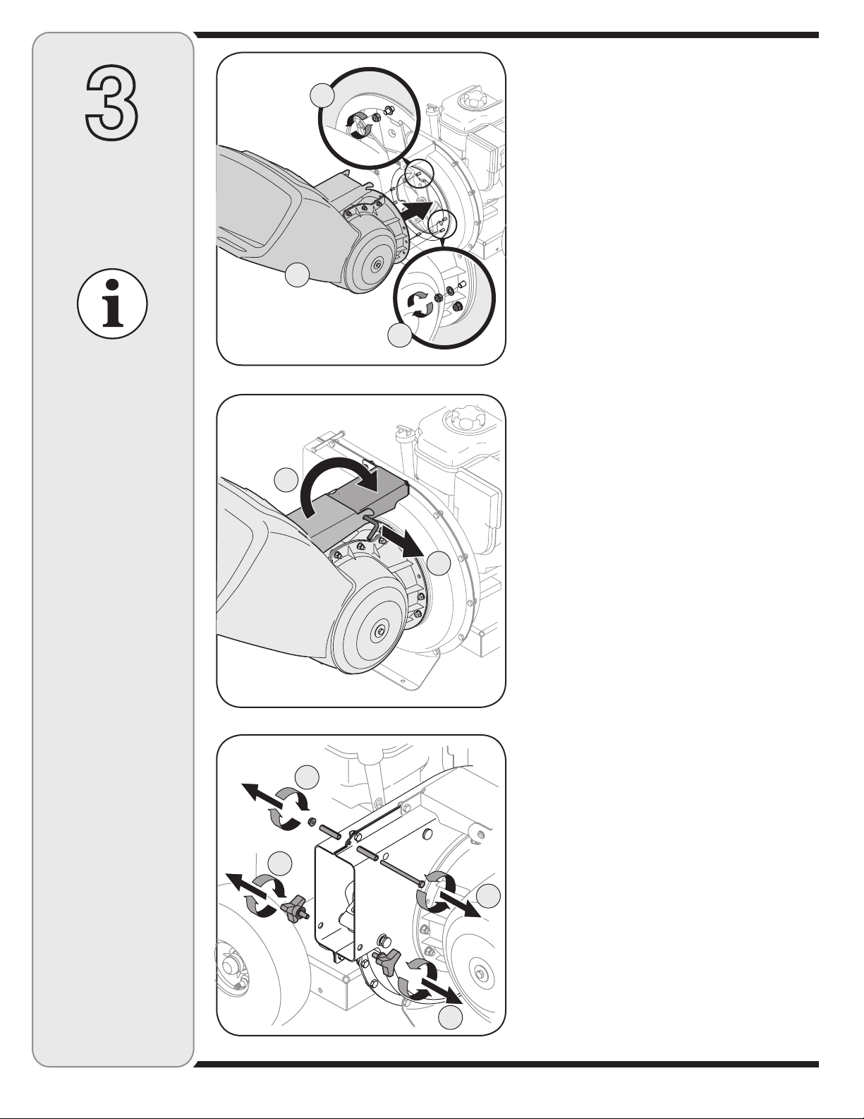
3
Configuración
de la cortadora
trituradora
IMPORTANTE
Esta unidad se envía sin
gasolina ni aceite en el
motor. Antes de operar
la máquina cargue el
motor con gasolina y
aceite como se indica en
el manual del motor por
separado.
NOTA: Todas las
referencias que contiene
este manual sobre los
lados derecho o izquierdo
de la cortadora trituradora
se hacen observando la
misma desde la posición
de operación únicamente.
Si existiera alguna
excepción, la misma será
especificada.
NOTA: Este Manual
del operador cubre una
gama de especificaciones
de productos de
varios modelos. Las
características y
funciones incluidas y/o
ilustradas en este manual
pueden no ser aplicables
a todos los modelos.
MTD LLC se reserva el
derecho de modificar las
especificaciones de los
productos, los diseños
y el equipo sin previo
aviso y sin generar
responsabilidad por
obligaciones de ningún
tipo.
IMPORTANTE: Esta unidad se envía sin gasolina ni
aceite en el motor. Antes de operar la máquina cargue el
A
motor con gasolina y aceite como se indica en el manual
del motor por separado.
Piezas sueltas dentro de la caja
a. Montaje de tolva d. Bolsa
b. Canal deflector e. Anteojos de seguridad
c. Canal de la cortadora f. Aceite de motor
Instalación de la tolva
Montaje
B
C
Figura 3-1
A
B
Figura 3-2
B
A
A
Figura 3-3
1. a. Saque seis tuercas hexagonales y arandelas de los
espárragos de la soldadura de la caja del motor. No
saque la placa de sostén. Vea la Figura 3-1.
b. Coloque el montaje de la tolva en posición delante
de la caja del motor, alineando los agujeros del
montaje del aro de la tolva con los espárragos de la
soldadura.
c. Deslice el montaje de la tolva sobre los espárragos
de la soldadura y vuelva a colocar las arandelas
y las tuercas hexagonales. No las ajuste por
completo.
2. a. Levante el montaje de la tolva hasta el montaje del
soporte de motor.
b. Deslice la varilla de liberación hacia afuera
levemente para enganchar el soporte de tolva en la
varilla. Vea la Figura 3-2.
c. Ajuste las seis tuercas hexagonales que unen el
montaje de la tolva a la caja del motor y ajuste
también las arandelas hexagonales que unen el
soporte de la tolva al montaje de la misma.
B
26
Page 27
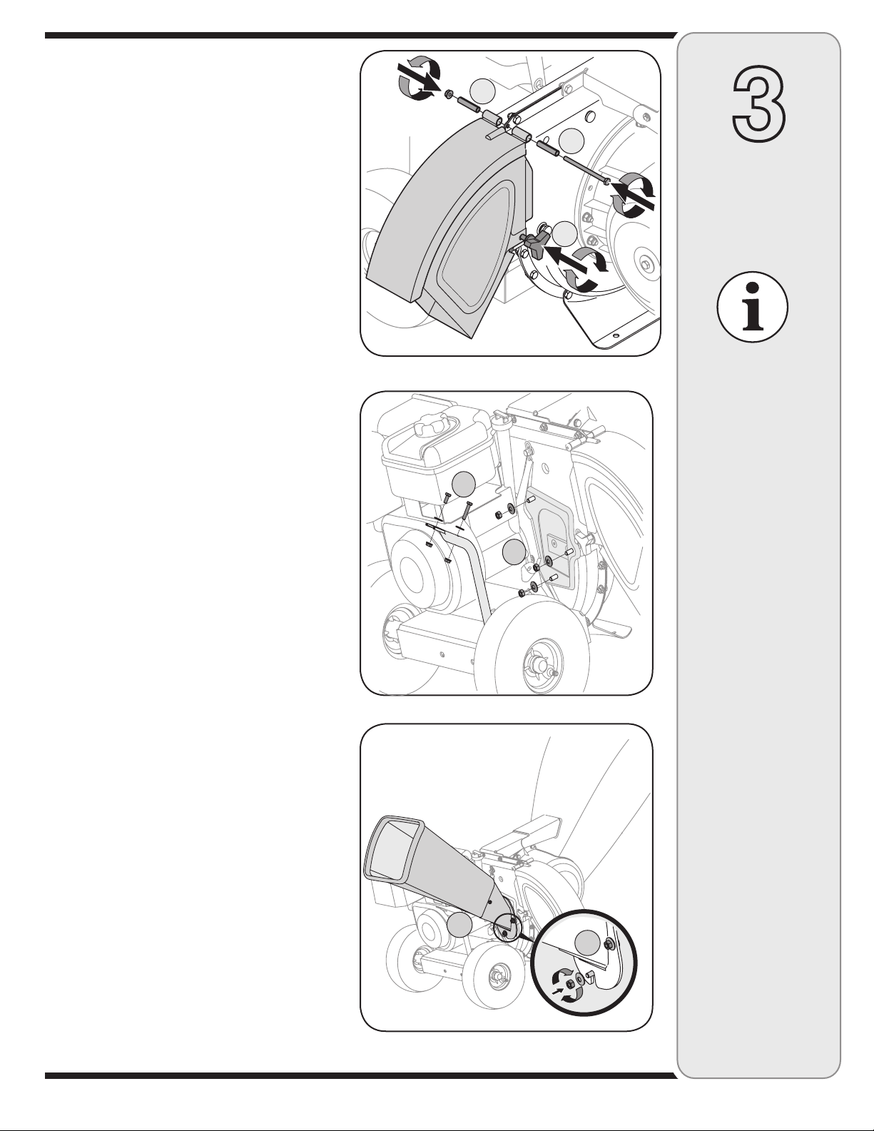
Colocación del canal deflector
3. a. Saque las perillas a mariposa de los costados de la
caja inferior del motor.
b. Saque la tuerca de seguridad hexagonal, los
separadores y el bulón hexagonal de la parte
superior de la caja del motor. Vea la Figura 3-3.
4. a. Ponga en línea el canal deflector en su posición
en la abertura de descarga e inserte el bulón
hexagonal con el separador a través de la bisagra
del canal deflector (los separadores van dentro de
las bisagras). Vea la Figura 3-4.
b. Coloque el segundo separador sobre el bulón
hexagonal dentro de la otra bisagra y ajústelo con
la tuerca de seguridad hexagonal.
c. Ajuste ambos costados del canal deflector a a la
caja del motor utilizando las perillas a mariposa
que había sacado anteriormente.
Colocación del canal
de la cortadora
(Modelo Serie 460)
5. a. Saque las tres arandelas curvas y las tuercas
hexagonales de los espárragos de la soldadura
que están alrededor de la abertura en el costado
de la caja del motor. Vea la Figura 3-5.
b. Saque los bulones hexagonales, las arandelas
planas y las tuercas de seguridad de los dos
agujeros del extremo superior de la traba de
sostén.
6. a. Ponga en línea el canal de la cortadora por encima
de los espárragos de la soldadura de manera que
la ranura en la base del canal mire hacia abajo.
b. Ajuste el canal de la cortadora con tres arandelas
curvas (con el lado curvo contra el canal de la
cortadora) y con las tuercas hexagonales que
había sacado anteriormente. No ajuste las tuercas
en este momento. Vea la Figura 3-6.
B
Figura 3-4
B
Figura 3-5
A
3
Configuración
de la cortadora
C
A
trituradora
IMPORTANTE
Esta unidad se envía sin
gasolina ni aceite en el
motor. Antes de operar
la máquina cargue el
motor con gasolina y
aceite como se indica en
el manual del motor por
separado.
NOTA: Todas las
referencias que contiene
este manual sobre los
lados derecho o izquierdo
de la cortadora trituradora
se hacen observando la
misma desde la posición
de operación únicamente.
Si existiera alguna
excepción, la misma será
especificada.
27
A
Figura 3-6
NOTA: Este Manual
del operador cubre una
gama de especificaciones
de productos de
varios modelos. Las
características y
funciones incluidas y/o
ilustradas en este manual
pueden no ser aplicables
a todos los modelos.
MTD LLC se reserva el
B
derecho de modificar las
especificaciones de los
productos, los diseños
y el equipo sin previo
aviso y sin generar
responsabilidad por
obligaciones de ningún
tipo.
Page 28
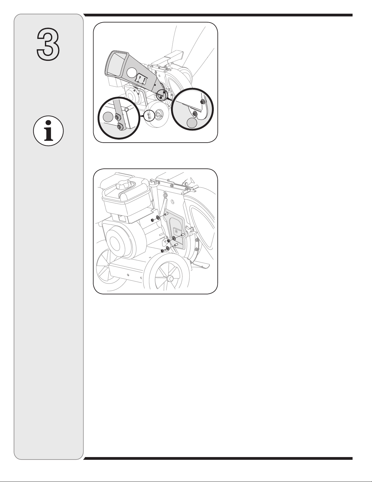
3
Configuración
de la cortadora
trituradora
7. La cortadora trituradora fue enviada con un extremo
de la traba de sostén ya unido al bastidor inferior.
Afloje pero no saque los bulones que unen la traba al
bastidor. Vea la Figura 3-7.
a. Ponga en línea los agujeros del canal con los
agujeros de la parte superior de la traba y una la
A
B
C
misma al canal de la cortadora con los elementos
de ferretería previamente retirados. Ajuste bien.
b. Ajuste los bulones que unen la traba de sostén al
bastidor.
c. Ajuste las tres tuercas de los espárragos de la
soldadura que sostienen el canal de la cortadora a
la caja del motor.
Colocación del canal
de la cortadora
IMPORTANTE
Esta unidad se envía sin
gasolina ni aceite en el
motor. Antes de operar
la máquina cargue el
motor con gasolina y
aceite como se indica en
el manual del motor por
separado.
NOTA: Todas las
referencias que contiene
este manual sobre los
lados derecho o izquierdo
de la cortadora trituradora
se hacen observando la
misma desde la posición
de operación únicamente.
Si existiera alguna
excepción, la misma será
especificada.
NOTA: Este Manual
del operador cubre una
gama de especificaciones
de productos de
varios modelos. Las
características y
funciones incluidas y/o
ilustradas en este manual
pueden no ser aplicables
a todos los modelos.
MTD LLC se reserva el
derecho de modificar las
especificaciones de los
productos, los diseños
y el equipo sin previo
aviso y sin generar
responsabilidad por
obligaciones de ningún
tipo.
Figura 3-7
Figura 3-8
(Modelo Serie 450)
8. a. Saque las tres arandelas curvas y las tuercas
hexagonales de los espárragos de la soldadura
que están alrededor de la abertura en el costado
de la caja del motor. Vea la Figura 3-8.
28
Page 29
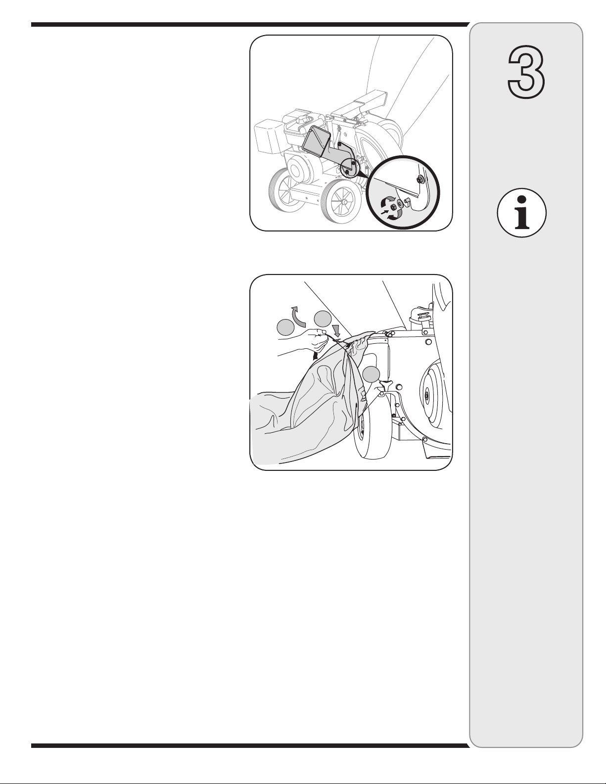
9. a. Ponga en línea el canal de la cortadora por encima
de los espárragos de la soldadura de manera que
la ranura en la base del canal mire hacia abajo.
b. Ajuste el canal de la cortadora con tres arandelas
curvas (con el lado curvo contra el canal de la
cortadora) y con las tuercas hexagonales que
había sacado anteriormente. En este momento
apriete las tuercas. Vea la Figura 3-9.
3
Configuración
Colocación de la bolsa
10. Para adosar la bolsa:
a. Coloque la abertura de la bolsa completamente
sobre el canal deflector.
b. Tire de la tira de extracción hasta que la bolsa
quede ajustada alrededor de la abertura del canal
deflector.
c. Vuelva a sujetar la tira de extracción sobre sí
misma, apriétela contra el canal deflector para que
quede firme en su lugar. Vea la Figura 3-10.
de la cortadora
trituradora
Figura 3-9
C
B
A
Figura 3-10
IMPORTANTE
Esta unidad se envía sin
gasolina ni aceite en el
motor. Antes de operar
la máquina cargue el
motor con gasolina y
aceite como se indica en
el manual del motor por
separado.
NOTA: Todas las
referencias que contiene
este manual sobre los
lados derecho o izquierdo
de la cortadora trituradora
se hacen observando la
misma desde la posición
de operación únicamente.
Si existiera alguna
excepción, la misma será
especificada.
29
NOTA: Este Manual
del operador cubre una
gama de especificaciones
de productos de
varios modelos. Las
características y
funciones incluidas y/o
ilustradas en este manual
pueden no ser aplicables
a todos los modelos.
MTD LLC se reserva el
derecho de modificar las
especificaciones de los
productos, los diseños
y el equipo sin previo
aviso y sin generar
responsabilidad por
obligaciones de ningún
tipo.
Page 30
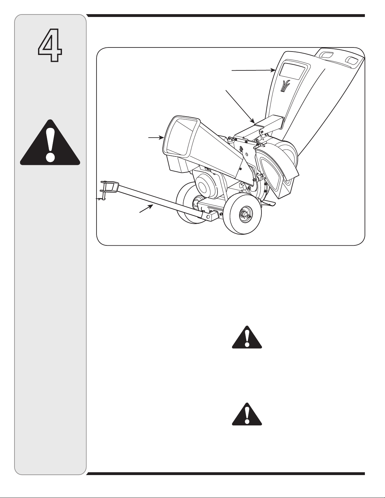
4
Funcionamiento
de la cortadora
trituradora
ADVERTENCIA
Al operar una
cortadora trituradora
puede ser que
objetos extraños
sean arrojados a los
ojos lo cual puede
dañarlos gravemente.
Utilice siempre los
anteojos de seguridad
provistos con esta
unidad o protectores
para ojos antes de
picar o triturar el
material o mientras
realiza ajustes o
reparaciones.
Sea sumamente
cuidadoso al
manipular la gasolina.
La gasolina es
sumamente inflamable
y sus vapores pueden
causar explosiones.
Nunca agregue
combustible a la
máquina en interiores
o mientras el motor
está caliente o en
funcionamiento.
Apague los cigarrillos,
cigarros, pipas y
otras fuentes de
combustión.
Conozca las propiedades
de la cortadora trituradora
Montaje de la tolva
Varilla de liberación
Canal de la
cortadora
Barra de remolque †
*Se muestra el modelo 464 con barra de remolque opcional
Figura 4-1
Ahora que ya ha ajustado su cortadora trituradora para
su funcionamiento, familiarícese con sus controles y
características. Estos se describen y se ilustran en esta
página. Este conocimiento le permitirá utilizar su nuevo
equipo a su máxima capacidad.
Canal de la cortadora
Permite que las ramas pequeñas de hasta 3” de
diámetro (2” en el caso del modelo serie 450) ingresen
al motor para ser picadas. Vea la Figura 4-1.
Montaje de la tolva
Permita que las hojas y las ramas pequeñas de hasta
1/2 de diámetro ingresen al motor para ser picadas y
trituradas. Bajando el montaje de la tolva se puede rastrillar
material e introducirlo dentro del mismo. Vea la Figura 4-1.
Varilla de liberación
La varilla de liberación está ubicada en el montaje del
soporte del motor y se usa para liberar o trabar la tolva
al momento de subir o bajar. Vea la Figura 4-1.
Barra de remolque (En caso de haber)
Use la barra de remolque para remolcar la cortadora
trituradora mediante una unidad de tracción hasta el
lugar de operación. Vea la Figura 4-1.
NOTA: Si su unidad no está equipada con una barra
de remolque, puede comunicarse con el servicio de
Asistencia al Cliente según las instrucciones de la
página 2 para consultar información sobre precio y
disponibilidad.
† Si es parte del equipo
Llenado de gasolina y aceite
1. Verifique el nivel del aceite y agregue más de ser
necesario. Siga las instrucciones del manual del
motor. Consulte el manual del motor para ver la
ubicación del depósito de aceite.
2. Realice el servicio del motor con gasolina como se
indica en el manual del motor. Consulte el manual del
motor para ver la ubicación del depósito de gasolina.
ADVERTENCIA: Sea sumamente
cuidadoso al manipular la gasolina.
La gasolina es sumamente
inflamable y sus vapores pueden
causar explosiones. Nunca agregue
combustible a la máquina en interiores
o mientras el motor está caliente o en
funcionamiento. Apague los cigarrillos,
cigarros, pipas y otras fuentes de
combustión.
ADVERTENCIA: Al operar una cortadora
trituradora puede ser que objetos
extraños sean arrojados a los ojos lo
cual puede dañarlos gravemente. Utilice
siempre los anteojos de seguridad
provistos con esta unidad o protectores
para ojos antes de picar o triturar el
material o mientras realiza ajustes o
reparaciones.
30
Page 31
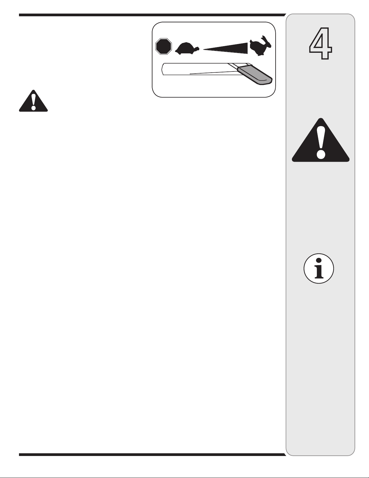
Este Manual del operador cubre una gama de
especificaciones de productos de varios modelos. Las
características y funciones incluidas y/o ilustradas en este
manual pueden no ser aplicables a todos los modelos. MTD
LLC se reserva el derecho de modificar las especificaciones
de los productos, los diseños y el equipo sin previo aviso y
sin generar responsabilidad por obligaciones de ningún tipo.
STOP
4
Encendido del motor
ADVERTENCIA: Nunca encienda el
motor en espacios cerrados o en una
zona poco ventilada. El escape del
motor contiene monóxido de carbono,
un gas inodoro y letal.
IMPORTANTE: Como este manual cubre varias
unidades de distintos modelos, es posible que se
apliquen instrucciones diferentes para el arranque de su
motor particular. Algunos motores pueden tener un grifo
de descompresión y otros no. Algunos motores pueden
tener interruptores de encendido/apagado, y otros no.
Algunas unidades emplean un sistema de obturación,
mientras que otras necesitan cebado. Estos factores
dependen de la marca y modelo del motor con el cual
está equipada su unidad particular. Por este motivo, por
favor consulte el manual del operador del motor para
averiguar el procedimiento correcto para el arranque.
1. Conecte el cable de la bujía a la misma. Compruebe
que la tapa metálica del extremo de la bujía esté bien
ajustada sobre la punta metálica de la bujía.
2.
Motores con palanca de obturación:
Mueva la palanca de obturación del motor a la
posición CHOKE (obturación). (Si el motor está tibio la
obturación puede no ser necesaria).
Motores con cebador:
Utilice el cebador del motor como se explica en el
manual por separado del motor.
3. La palanca de control del regulador está ubicada
sobre el motor. Mueva la palanca de control del
regulador del motor a la posición FAST (velocidad
rápida) o START (encendido). Vea la Figura 4-2.
4. Tome la manija del arrancador y saque la cuerda
lentamente hasta que el motor alcance el comienzo
del ciclo de compresión (la cuerda tirará un poco más
fuerte en este punto).
NOTA: Escuchará un sonido cuando alcance el comienzo
del ciclo de compresión. Este sonido es causado por el
descebado y los topes que son parte del mecanismo de
la trituradora y es de esperar hasta que el motor alcance
la máxima velocidad.
5. Tire de la cuerda con un golpe rápido y continuo de
todo el brazo. Sujete fuerte la manija del arrancador.
Deje que la soga se enrolle lentamente.
6. Repita los pasos anteriores hasta que el motor se
encienda. Cuando se enciende el motor mueva el
control de obturación (si está incluido) gradualmente
hasta la posición RUN (en marcha).
Figura 4-2
Detención del motor
1. Mueva la palanca de control del regulador a la
posición STOP (detención) u OFF (apagado).
2. Desconecte el cable de la bujía y póngalo haciendo
masa contra el motor.
NOTA: Si desea instrucciones más detalladas consulte
el manual del motor embalado junto con la unidad.
Uso de la cortadora trituradora
El desecho que se junta en los patios como por ejemplo
hojas y las agujas de los pinos se pueden rastrillar
e introducir dentro del montaje de la tolva para ser
triturado. Después que ha triturado el material con las
cuchillas de desgranar del montaje del motor, el mismo
será descargado hacia afuera por la abertura o hacia
adentro de la bolsa colectora. Sólo utilice la máquina
para triturar o picar el tipo de material vegetal que se
encuentra en un patio normal (es decir, ramas, hojas,
ramas pequeñas, etc.) Evite las plantas fibrosas, por
ejemplo, las de tomate, hasta que estén totalmente
secas. Pueden ingresar al canal de la cortadora ramas
pequeñas de hasta 3” de diámetro (2” en el caso del
modelo serie 450).
Cómo bajar el montaje de la tolva
1. Con una mano tome la manija que se encuentra en
la parte superior del montaje de la tolva y levántela
levemente.
2. Con la otra mano tire hacia afuera de la varilla de
liberación y baje el montaje de la tolva hasta el piso.
Vea la Figura 4-1.
Cómo descargar la bolsa
1. Suelte la cuerda de extracción y afloje la bolsa de la
abertura del canal deflector.
2. Vacíe la bolsa y vuelva a colocarla en la abertura
del canal de descarga. Tire de la cuerda hasta que
la bolsa esté ajustada alrededor de la abertura del
canal y sujete la cuerda apretándola contra el canal
deflector.
IMPORTANTE: La pantalla de desgranado está
ubicada dentro de la caja en la zona de descarga. Si
se tapa la pantalla de desgranado, sáquela y límpiela
como se indica en la sección 5: MANTENIMIENTO DE
LA CORTADORA TRITURADORA. Para obtener el
mejor resultado también es importante mantener afilada
la cuchilla de la cortadora.
Funcionamiento
de la cortadora
trituradora
ADVERTENCIA
Nunca encienda el
motor en espacios
cerrados o en una
zona poco ventilada.
El escape del motor
contiene monóxido
de carbono, un gas
inodoro y letal.
NOTA: Escuchará un
sonido cuando alcance
el comienzo del ciclo de
compresión. Este sonido es
causado por el descebado
y los topes que son parte
del mecanismo de la
trituradora y es de esperar
hasta que el motor alcance
la máxima velocidad.
31
Page 32
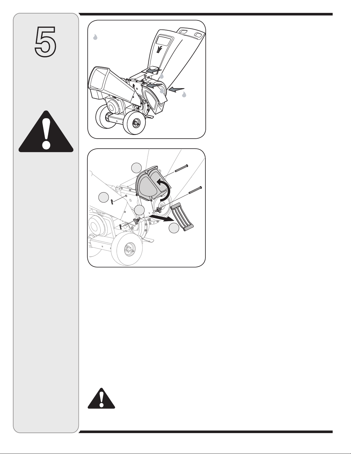
5
Mantenimiento
de la cortadora
Lubrique estos
puntos antes
de volver a
ensamblar.
Lubricación
1. Lubrique la varilla y el resorte de liberación con aceite
liviano una vez por temporada. Vea la Figura 5-1.
2. Lubrique los puntos de pivote del montaje de la tolva con
aceite liviano una vez por temporada. Vea la Figura 5-1.
3. Lubrique los puntos de pivote del canal de descarga con
aceite liviano una vez por temporada. Vea la Figura 5-1.
4. Siga el manual adjunto del motor para conocer las
instrucciones y el programa de lubricación del mismo.
trituradora
ADVERTENCIA
Detenga siempre el
motor, desconecte
la bujía y haga masa
contra el motor antes
de limpiar, lubricar
o llevar a cabo
cualquier clase de
mantenimiento en su
máquina.
*Se muestra el modelo 464
Figura 5-1
B
C
A
D
*Se muestra el modelo 464
Figura 5-2
Recomendaciones generales
1. Respete siempre las reglas de seguridad cuando
realice tareas de mantenimiento.
2. La garantía de esta cortadora trituradora no cubre
elementos que han estado sujetos al mal uso o la
negligencia del operador. Para recibir el reembolso
total de la garantía, el operador deberá dar
mantenimiento a la cortadora trituradora como se
indica en este manual.
3. El cambio de la velocidad controlada del motor
invalidará la garantía del motor.
4. Todos los ajustes deben ser verificados por lo
menos una vez en cada estación.
5. Revise periódicamente todos los sujetadores y
compruebe que estén bien ajustados.
ADVERTENCIA: Detenga siempre el
motor, desconecte la bujía y haga
masa contra el motor antes de limpiar,
lubricar o llevar a cabo cualquier clase
de mantenimiento en su máquina.
Cuidados para el motor
1. Mantenga el nivel de aceite como se indica en el manual.
2. Limpie el filtro de aire cada 25 horas en condiciones
normales de uso. Limpie a intervalos de pocas horas
cuando haya mucho polvo. Consulte el manual del motor.
3. Limpie la bujía y restablezca la distancia disruptiva
por lo menos una vez por temporada. Consulte el
manual del motor para conocer las especificaciones
para el tipo de bujía y la distancia disruptiva correctas.
4. Limpie el motor regularmente con un trapo o cepillo.
Mantenga limpio el sistema de enfriamiento (área del
soplador) para permitir la circulación apropiada de
aire. Quite todo el césped, polvo y residuos del área
del silenciador.
Extracción de la pantalla de desgranado
Si la zona de descarga se tapa, saque la pantalla de
desgranado y limpie la zona como se indica a continuación:
1. Detenga el motor y compruebe que la cortadora
trituradora se haya detenido por completo.
2. Desconecte el cable de la bujía y póngalo haciendo
masa contra el motor.
3. a. Retire la bolsa y dos perillas a mariposa a cada
lado del canal deflector. Vea la Figura 5-2.
b. Levante el canal deflector para mantenerlo fuera
del paso.
c. Saque los dos broches de horquilla de cada
pasador de horquilla que se extiende cruzando la
caja y saque los pasadores.
d. Saque la pantalla de desgranado del interior de la
caja y limpie la pantalla cepillándola o lavándola
con agua. Vea la Figura 5-2.
4. Vuelva a colocar la pantalla y asegúrese de
reensamblarla con el lado curvo hacia abajo.
5. Vuelva a unir el canal deflector con los elementos de
ferretería previamente sacados y conecte la bolsa a la
unidad.
Afilado o recambio de las cuchillas
de la cortadora
1. Desconecte el cable de la bujía y póngalo de manera
que haga masa contra el motor.
2. Saque la pantalla de desgranado conforme se indica
en la sección anterior.
3. Saque el canal de la cortadora quitando tres tuercas
hexagonales y arandelas.
4. Saque del bastidor la traba de sostén del canal de la
cortadora ( Modelo serie 460) quitando los bulones
hexagonales.
5. Gire el montaje del motor en forma manual hasta
32
Page 33
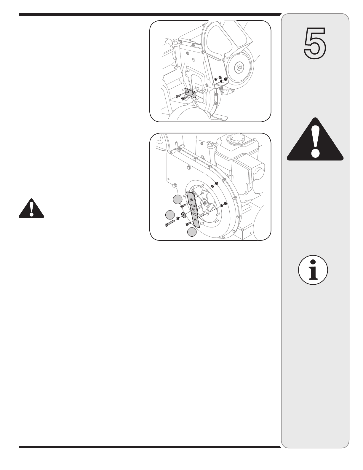
ubicar una de las dos cuchillas de la cortadora en la
abertura del canal de la cortadora.
6. Para sacar la cuchilla saque los tornillos hexagonales
internos, las arandelas de seguridad y las tuercas
hexagonales que la sujetan al motor. Guarde los
elementos de ferretería. Vea la Figura 5-3.
NOTA: Use una llave hexagonal de 3/16” (Allen) en el
exterior de la cuchilla y una llave de tubo de 1/2” (o cubo)
en el interior del motor. Sostenga la llave Allen firmemente
y gire la llave de tubo (o cubo) para aflojar la tuerca.
7. Coloque una cuchilla de repuesto (Número de pieza
781-0490) con los elementos de ferretería que extrajo
anteriormente o afílela.
IMPORTANTE: Cuando afila la cuchilla, protéjase las manos
utilizando guantes. Siga el ángulo original de afilado y
asegúrese de extraer una cantidad igual de cada cuchilla.
8. Para reemplazar la otra cuchilla, gire el motor para
exponer la seguna cuchilla y repita los pasos anteriores.
NOTA: Compruebe que las cuchillas se reensamblen con
el filo hacia arriba. Ajuste los elementos de ferretería a
250 - 300 pulgadas libras.
Afilado o cambio de la cuchilla de la
trituradora
ADVERTENCIA: Las cuchillas de la
cortadora del motor son filosas. Utilice
guantes de trabajo de cuero para
protegerse las manos.
1. Detenga el motor y verifique que todas las piezas
móviles se hayan detenido por completo.
2. Desconecte el cable de la bujía y póngalo de manera
que haga masa contra el motor.
3. Baje el montaje de la tolva y trabe la caja.
4. Saque las seis tuercas hexagonales de seguridad y las
arandelas planas de los espárragos de la soldadura de la
caja de desgranado. Guarde los elementos de ferretería.
5. Con mucho cuidado separe el montaje de la tolva del
montaje del motor y retire la placa de sostén.
NOTA: Cuando vuelva a montar la placa de sostén
compruebe que la aleta grabada mire hacia adentro
hacia el motor.
6. Saque las dos perillas a mariposa y las arandelas
curvas que unen el canal deflector y levántelo.
7. Inserte un tubo de 1/2” o 3/4” de diámetro a través de
la pantalla de desgranado hacia el interior del motor
para evitar que el mismo gire o saque la pantalla
de desgranado e inserte un trozo de madera en la
abertura del canal.
8. a. Saque los dos tornillos hexagonales internos,
las arandelas de seguridad y las tuercas de
seguridad hexagonales que sujetan la cuchilla de
la trituradora al motor.
b. Saque el perno hexagonal, la arandela de seguridad
y la arandela plana para liberar totalmente la cuchilla
de la trituradora. Vea la Figura 5-4.
NOTA: Use una llave hexagonal de 3/16” (Allen) en el
exterior de la cuchilla de la trituradora y una llave de
tubo de 1/2” (o cubo) en el interior de la cuchilla de la
Figura 5-3
A
B
A
Figura 5-4
trituradora. Sostenga la llave Allen firmemente y gire
la llave de tubo (o cubo) para aflojar la tuerca. Tenga
precaución cuando saque la cuchilla para evitar el
contacto con los espárragos de la soldadura de la caja.
IMPORTANTE: Cuando afile la cuchilla, siga el ángulo
original de afilado como guía. Es de suma importancia
que cada extremo de corte sea desbastado de igual
manera para evitar que la cuchilla quede desequilibrada.
Si la cuchilla está desequilibrada producirá una vibración
excesiva cuando gire a alta velocidad y puede dañar la
unidad. Se puede probar la cuchilla balanceándola sobre
un destornillador o clavo. Saque metal del lado pesado
hasta que quede bien balanceada.
Almacenamiento de la cortadora
trituradora
Se deben seguir estos pasos para la preparación de la
cortadora trituradora para su almacenamiento.
1. Limpie el equipo por completo.
2. Limpie el equipo con un trapo con aceite para evitar
que se oxide.
3. Consulte el manual del motor para conocer las
instrucciones para el almacenamiento correcto del
mismo
4. Almacene la unidad en una zona limpia y seca. No
la almacene cerca de materiales corrosivos como
por ejemplo fertilizantes.
5
Mantenimiento
de la cortadora
trituradora
ADVERTENCIA
Las cuchillas de
trituración y la
cuchilla de corte del
motor son filosas.
Utilice guantes de
trabajo de cuero para
protegerse las manos.
IMPORTANTE
Compruebe que las
cuchillas de la cortadora
se reensamblen con
el filo hacia arriba.
Ajuste los elementos de
ferretería a 250 - 300
pulgadas libras.
IMPORTANTE
Cuando vuelva a
montar la cuchilla de
trituración ajuste el
bulón central entre
550 y 700 pulgadas
libras y los dos bulones
exteriores entre 250 y
350 pulgadas libras.
33
Page 34
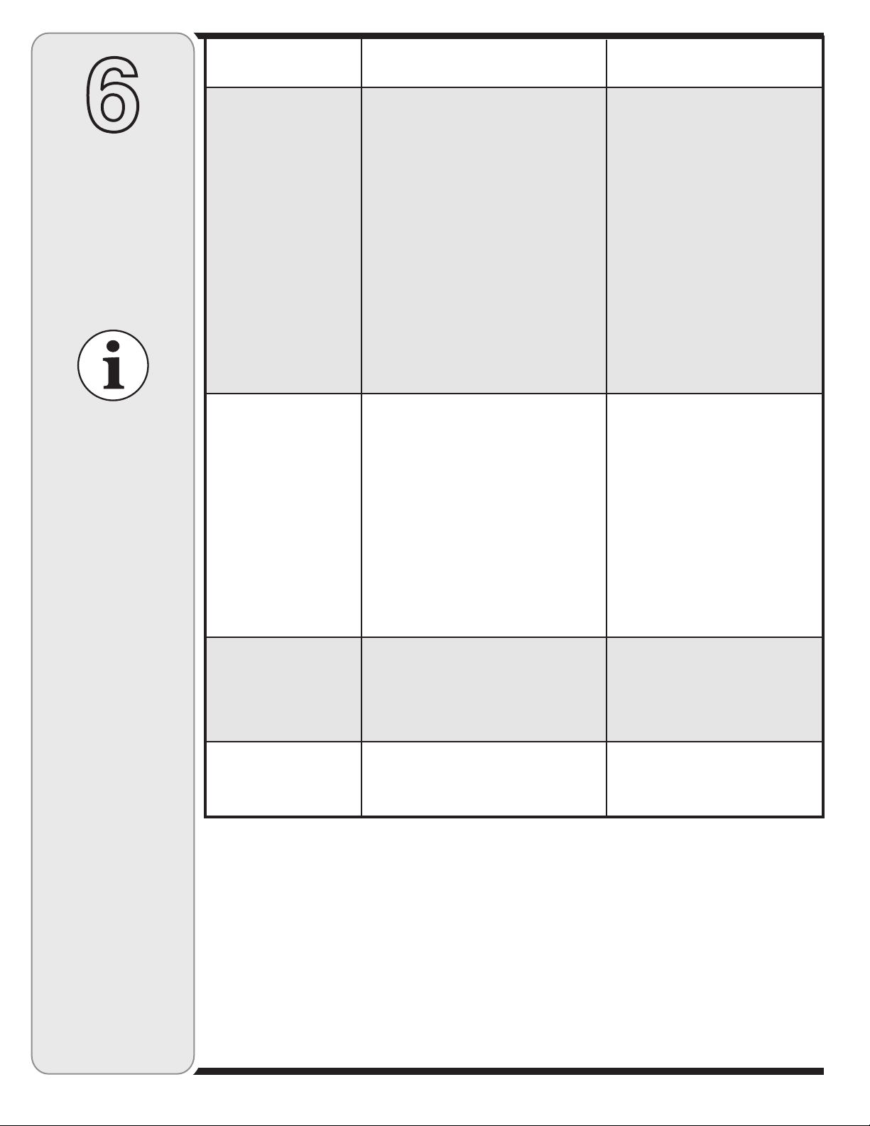
6
Solución de
problemas
Si debe realizar
reparaciones más
importantes que las
enunciadas aquí,
comuníquese con
el distribuidor local
autorizado.
El motor no arranca
El motor funciona de
manera errática
Causa Problema Remedio
La palanca del regulador no está en
1.
la posición de arranque correcta.
La palanca de obturación no está en
2.
la posición ON (encendido).
Se ha desconectado el cable de la
3.
bujía.
La bujía no funciona correctamente.
4.
El tanque de combustible está vacío
5.
o el combustible es viejo.
No se puede tirar de la cuerda de
6.
retroceso.
La línea del combustible está
7.
bloqueada.
Motor ahogado.
8.
La unidad está funcionando en la
1.
posición CHOKE (obturación).
El cable de la bujía está flojo.
2.
El combustible es viejo.
3.
Agua o suciedad en el sistema del
4.
combustible.
El filtro de aire está sucio.
5.
RPM del motor bajas
6.
Es necesario ajustar el carburador
7.
Mueva la palanca del regulador a
1.
la posición START (inicio)/RUN
(dirigido).
Ponga el interruptor en la
2.
posición CHOKE (obturación).
Conecte el cable a la bujía.
3.
Limpie, ajuste la distancia
4.
disruptiva o cambie.
Llene el tanque con gasolina
5.
limpia y fresca.
Hay una obstrucción en el motor.
6.
Desconecte el cable de la bujía y
retire el objeto atascado.
Limpie la línea del combustible.
7.
Espere unos minutos para
8.
reencender, no realice el cebado.
Cambie la palanca de obturación
1.
a la posición OFF (apagado).
Conecte y ajuste el cable de la
2.
bujía.
Llene el tanque con gasolina
3.
limpia y fresca.
Vacíe el tanque del combustible.
4.
Vuelva a llenarlo con combustible
limpio.
Consulte el manual del motor.
5.
Siempre accione el motor con el
6.
estrangulador al máximo.
Consulte el manual del motor.
7.
El motor recalienta
Saltos ocasionales
(pausas) a alta
velocidad
1. El nivel de aceite del motor es bajo.
2. Flujo de aire restringido.
3. El carburador no está ajustado
correctamente.
1. La distancia disruptiva de la bujía es
muy pequeña.
2. Ajuste de la mezcla del carburador mal
realizada.
1. Llene el cárter con aceite
adecuado.
2. Retire el alojamiento del soplador
y límpielo.
3. Consulte el manual del motor.
1. Quite la bujía y ajuste el hueco.
2. Consulte el manual del motor.
34
Page 35
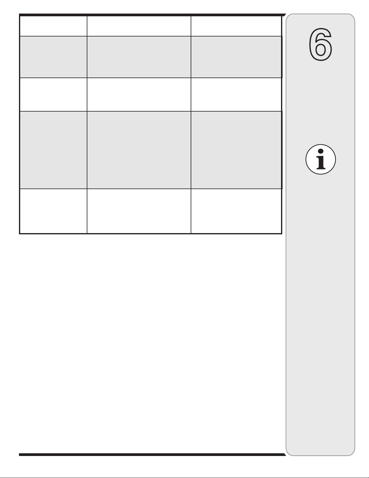
Causa Problema Remedio
Funciona mal en
marcha lenta
Demasiada vibración
La unidad no descarga
La tasa de descarga
se reduce de manera
considerable o cambia
la composición del
material descargado
1. Bujía atorada, averiada o exceso de
distancia disruptiva.
2. Carburador ajustado incorrectamente.
3. El filtro de aire está sucio.
1. Hay partes que están flojas o el motor
está dañado.
El área de descarga está tapada
1.
Hay un objeto extraño en el motor
2.
RPM del motor bajas
3.
RPM del motor bajas
1.
La hoja de la cortadora está
2.
desafilada
1. Sustituya la bujía y ajuste el
hueco.
2. Consulte el manual del motor.
3. Consulte el manual del motor.
1. Detenga el motor de inmediato y
desconecte el cable de la bujía.
Consulte a un distribuidor
autorizado.
Detenga el motor de inmediato y
1.
desconecte el cable de la bujía.
Limpie la pantalla de desgranado
y el interior de la abertura de
descarga.
Detenga el motor y desconecte el
2.
cable de la bujía. Saque el objeto
extraño del motor.
Siempre accione el motor con el
3.
estrangulador al máximo.
Siempre accione el motor con el
1.
estrangulador al máximo.
Reemplace la hoja de la corta-
2.
dora o contacte a un distribuidor
autorizado.
6
Solución de
problemas
Si debe realizar
reparaciones más
importantes que las
enunciadas aquí,
comuníquese con
el distribuidor local
autorizado.
35
Page 36

GARANTÍA LIMITADA DEL FABRICANTE PARA
La garantía limitada que se extiende a continuación es otorgada por
la empresa MTD LLC y cubre mercaderías nuevas compradas y
utilizadas en los Estados Unidos, sus posesiones y territorios.
“MTD” garantiza este producto por defectos de materiales y de
fabricación por un período de dos (2) años a partir de la fecha de la
compra original y reparará o cambiará sin cargo cuando lo considere
pertinente todas las piezas con defectos de materiales o de fabricación.
Esta garantía limitada sólo se aplicará si el producto ha sido operado y
mantenido de acuerdo con las instrucciones del Manual del Operador
que se proporciona con el producto y no ha sido sujeto a uso inapropiado, abuso, uso comercial, abandono, accidente, mantenimiento
incorrecto, alteración, vandalismo, robo, incendio, inundación o algún
daño debido a otro peligro o desastre natural. El daño resultante por la
instalación o el uso de piezas, accesorios o uniones no aprobados por
MTD para su uso con el(los) producto(s) incluido(s) en este manual
anulará la garantía en lo que respecta a esos daños.
Se garantiza que las piezas con desgaste normal están libres de defectos en los materiales o de fabricación por un período de treinta (30)
días a partir de la fecha de compra. Las piezas o componentes sujetos
a desgaste normal incluyen pero no se limitan a: baterías, correas,
cuchillas, adaptadores para cuchillas, bolsas para pasto, ruedas para
la plataforma de la podadora tractor, asientos, zapatas antideslizantes,
placas, gomas de corte y neumáticos.
CÓMO SOLICITAR Y OBTENER SERVICIO TÉCNICO: El servicio de
la garantía está disponible, CON PRUEBA DE COMPRA, a través del
distribuidor local autorizado para el mantenimiento. Para localizar al
distribuidor en su área, busque en las páginas amarillas de su localidad
o contacte a MTD LLC al Apartado Postal 361131, Cleveland, Ohio
44136-0019, o llame al 1-800-800-7310 ó 1-330-220-4683 o entre a la
página Web en www.mtdproducts.com.
Esta garantía limitada no lo cubrirá en los siguientes casos:
a. El motor y las piezas componentes del mismo. Estos productos
pueden tener garantía del fabricante por separado. Consulte los
términos y condiciones de la garantía aplicable del fabricante.
b. Las bombas para el corte de madera, las válvulas y los cilindros
tienen una garantía independiente de un año.
c. Los artículos necesarios para el mantenimiento de rutina como por
ejemplo lubricantes, filtros, afiladores de cuchillas, los ajustes de los
frenos, del embrague o de la plataforma y el deterioro normal del
acabado exterior debido al uso o exposición.
d.
Servicio no realizado por el distribuidor autorizado para el mantenimiento.
e. MTD no proporciona ninguna garantía por productos vendidos o ex-
portados fuera de los Estados Unidos de América, sus posesiones
y territorios, excepto aquellos que fueren vendidos a través de los
canales autorizados por MTD para la distribución de exportaciones.
f. Piezas de reemplazo que no son piezas genuinas de MTD.
g. Gastos de transporte y llamadas por servicios técnicos.
No se aplican garantías implícitas, incluidas las garantías
implícitas de comerciabilidad o de adecuación para un propósito
determinado, después del período de aplicación de la garantía escrita expresa extendida más arriba para las piezas de acuerdo con
su identificación. Ninguna otra garantía expresa, oral o escrita,
excepto la mencionada anteriormente, extendida por personas o
personas jurídicas, incluidos los distribuidores o los minoristas
con respecto a los productos, obligará a MTD. Durante el plazo
de la garantía el único recurso es la reparación o reemplazo del
producto como se indicó anteriormente.
Las disposiciones incluidas en esta garantía proveen el recurso
único y exclusivo que surge de las ventas. MTD no será responsable por pérdidas o daños incidentales o directos, incluyendo
sin límites, los gastos incurridos para los servicios de cuidado
del pasto de reemplazo o cambio, o los gastos de alquiler para
reemplazar de manera transitoria un producto bajo garantía.
Algunos estados no permiten la exclusión o limitación de los daños y
perjuicios incidentales o directos, o las limitaciones sobre la duración
de las garantías implícitas, por lo que las exclusiones o limitaciones
mencionadas anteriormente pueden no serle de aplicación.
En ningún caso se obtendrá una compensación mayor al monto del
precio de compra del producto vendido. La alteración de las carac-
terísticas de seguridad del producto anulará esta garantía. Usted
asume el riesgo y la responsabilidad por las pérdidas, daños o lesiones
que sufran Usted y sus bienes y / o otras personas y sus bienes como
consecuencia del uso, del uso incorrecto o de la imposibilidad de uso
de este producto.
Esta garantía limitada alcanza solamente al comprador original, o a la
persona que recibió el producto de regalo.
CÓMO SE RELACIONA LA LEGISLACIÓN ESTATAL CON ESTA GARANTÍA: Esta garantía limitada le otorga derechos legales específicos
y usted también puede contar con otros derechos que varían de un
estado a otro.
IMPORTANTE: El propietario debe presentar prueba de compra
original para obtener la cobertura de la garantía.
MTD LLC, P.O. BOX 361131 CLEVELAND, OHIO 44136-0019, Teléfono: 1-800-800-7310, 1-330-220-4683
 Loading...