

Page 1
owiers GUIDE
• ASSEMBLY • OPERATION • MAINTENANCE •
Made
Made
in
AMERICA
WARNING: This unit is equipped with an internal combustion engine and should not be used
on or near any unimproved forest-covered, brush-covered or grass-covered land unless the
engine’s exhaust system is equipped with a spark arrester meeting applicable local or state
laws (if any). If a spark arrester is used, it should be maintained in effective working order by
the operator.
In the State of California the above is required by law (Section 4442 of the California Public
Resources Code). Other states may have similar laws. Federal laws apply on federal lands. A
spark arrester for the muffler is available through your nearest engine authorized service
dealer or contact the service department, RO. Box 368022, Cleveland, Ohio 44136-9722.
FORM NO. 770-8576M
Page 2

A
IMPORTANT : SAFE OPERATION PRACTICES
THIS SYMBOL POINTS OUT IMPORTANT SAFETY INSTRUCTIONS WHICH, IF NOT FOLLOWED, COULD ENDANGER THE PERSONAL
SAFETY AND/OR PROPERTY OF YOURSELF AND OTHERS. READ AND FOLLOW ALL INSTRUCTIONS IN THIS MANUAL BEFORE
AHEMPTING TO OPERATE YOUR TILLER. FAILURE TO COMPLY WITH THESE INSTRUCTIONS MAY RESULT IN PERSONAL INJURY.
WHEN YOU SEE THIS SYMBOL—
^HEED ITS WARNING.
A
DANGER: Your tiller was bi ilt to be operated according to the rules for safe operation in this manual. As with
A
DANGER'
univucn. cgp3|,|g qi g„, )utating hands and feet. Failure to observe the following safety instructions could
_______ __ __
result in serious injury or death.
equipmt nt, careiessness or error on the part of the operator can result in serious injury,
___________ __ __ __ _____________ __ __ _____________ __ __ ______
I. GENERAL OPERATION
1. Read this owner’s guide carefully in its entirety bet ore attempt
ing to assemble this machine. Read, understand, £ nd tollow all
instructions on the machine and in the manual(s) tefore opera
tion. Be completely familiar with the controls anil the proper
use of the machine before operating it. Keep this manual in a
safe place for future and regular reference and ’or ordering
replacement parts.
2. Your tiller is a powerful tool, not a plaything. The'etore, exer
cise extreme caution at all times. Your unit has been designed
to perform one job: to till soil. Do not use it for ar y other pur
pose.
3. Never allow children under age 14 to operate the unit. Children
14 years and older should only operate the unit under close
parental supervision. Only responsible individuuls who are
familiar with these rules of safe operation should be allowed to
use your unit.
4. Do not operate tiller while under the influence o’ alcohol or
drugs.
5. Keep the area of operation clear of all persons, particularly
small children and pets. Stop the engine when thny are in the
vicinity of your tiller.
6. Wear sturdy, rough-soled work shoes and close 1 tting slacks
and shirt. Shirt and slacks that cover the arms aid legs and
steel-toed shoes are recommended. Do not wear loose fitting
clothes or jewelry and secure hair so it is abo/e shoulder
length. They can be caught in moving parts. Nevir operate a
unit in bare feet, sandals or sneakers.
7. Operate tiller only in daylight or good artificial light.
8. Do not start tiller unless the shift lever (it providi d) is in the
neutral (N) position.
9. Do not allow anyone to stand or walk in front o tiller when
starting or running engine.
10. Do not place feet or hands on or near the tines wher starting the
engine or while the engine is running.
II. Never attempt to make depth bar, tine width, cabk, handle, or
wheel adjustments while the engine is running.
12. Do not leave the tiller unattended with the engine ruining.
13. Before attempting to remove rocks, bricks and o her objects
from tines, stop the engine and be sure the tines hive stopped
completely. Disconnect the spark plug wire and n ove it away
from the spark plug.
14. If your machine should start making an unusual no se or vibra
tion, immediately stop the engine and allow the machine to
come to a complete stop. Disconnect the spark pUg wire and
move it away from the spark plug. Take the followii g steps;
• Inspect for damage.
• Repair or replace any damaged parts.
• Check for any loose parts and tighten to assuri continued
safe operation.
15. Muffler and engine become hot and can cause a b irn. Do not
touch.
16. Keep all shields, guards and safety devices in place and operat
ing properly.
17. Use caution when tilling near fences, buildings and under
ground utilities. Rotating tines can cause damage or injury.
18. Do not operate engine if air cleaner or cover over carburetor airintake is removed, except for adjustment. Removal of such
parts could create a fire hazard.
19. Only use accessories approved for this machine by the manu
facturer. Read, understand, and follow all instructions provided
with the approved accessory.
20. If situations occur which are not covered by this manual, use
care and good judgment. Contact your dealer tor assistance.
II. CHILDREN
> Tragic accidents can occur if the operator is not alert to the presence
of small children. Children are often attracted to the tilling activity.
Never assume that children will remain where you last saw them.
1. Keep children out of the work area and under the watchful eye
of a responsible adult other than the operator.
2. Be alert and turn the unit off if a child enters the area.
3. Never allow children under the age of 14 to operate the tiller.
III. SERVICE
i 1. Use extreme care in handling gasoline and other fuels. They are
extremely flammable and the vapors are explosive.
a. Store fuel and oil in approved containers, away from heat
and open flame, and out of the reach of children. Check and
add fuel before starting the engine. Never remove gas cap or
add fuel while the engine is running. Allow engine to cool at
least two minutes before refueling.
b. Replace gasoline cap securely and wipe off any spilled gaso
line before starting the engine as it may cause a fire or explo
sion.
c. Extinguish all cigarettes, cigars, pipes and other sources of
ignition.
d. Never refuel unit indoors because flammable vapors will
accumulate in the area.
e. Never store the machine or fuel container inside where there
is an open flame or spark such as a gas hot water heater,
space heater, clothes dryer or furnace.
2. Never run your machine in an enclosed area as the exhaust
from the engine contains carbon monoxide, which is a odorless,
tasteless and deadly poisonous gas.
3. To reduce fire hazard, keep engine and muffler free of leaves,
grass, and other debris build-up. Clean up fuel and oil spillage.
Allow unit to cool at least 5 minutes before storing.
4. Before cleaning, repairing, or inspecting, make certain the tines
and all moving parts have stopped. Disconnect the spark plug
wire and keep wire away from spark plug to prevent accidental
starting. Do not use flammable solutions to clean air filter.
5. Keep all nuts, bolts, and screws tight to be sure the equipment
is in safe working condition.
Page 3

6. Nevertamper with safety devices. Check their proper operation
reguiarly.
7. Do not alter or tamper with the engine’s governor setting. The
governor controls the maximum safe operating speed of the
engine. Over-speeding the engine is dangerous and will cause
damage to the engine and to other moving parts of the machine.
OWNER’S
MANUAL
SAFETY LABEL
WARNING — YOUR RESPONSIBILITY
A
Restrict the use of this power machine to persons who read,
understand and follow the warnings and instructions in this
manual and on the machine.
Page 4
ASSEMBLY INSTRUCTIONS
IMPORTANT: This unit is shipped WITHOUT GASO
LINE or OIL. After assembly, see separate engine
manual for proper fuel and engine oil recommen
dations.
NOTE: Left and right is determined from the i operator's
position, standing behind the tiller.
TOOLS REQUIRED FOR ASSEMBLY
(1)-1/2" Wrench or Socket*
(l)-Pair of Pliers
(1)-3/8" Wrench*
*An adjustable wrench may be used.
This owner's guide covers two différer t model
tillers. Model 340 has forward tine drive only.
Model 390 has both forward and reverse ti ie drive.
Follow only the instructions which pertain to your
model tiller. See the model plate on your tiller for
the correct model number.
REMOVING UNIT FROM CARTON
1. Remove staples, break glue on top flaps, or cut
tape at carton end and peel along top fla ) to open
carton.
2. Remove all loose parts included with unil.
3. Cut along dotted lines and lay carton dovm flat.
4. Remove packing material.
5. Roll or slide unit out of carton. Check carton
thoroughly for loose parts.
6. Extend control cable(s) to the rear of the tiller and
lay them on the floor. Be careful not to bend or
kink control cable(s).
All hardware required for assembly has been placed in
position on the tiller.
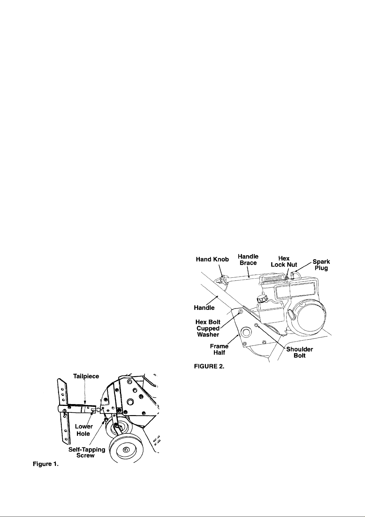
AHACHING THE HANDLE ASSEMBLY
1. Remove the hex bolt and cupped washer from the
top right side of the frame halves. Hold the cable
guide bracket on the left side of the frame as it will
fall when the bolt is removed. (See Figure 2)
2. Insert the handle assembly between the two
frame halves. Insert the hex bolt just removed
through the frame halves, handle assembly, and
into the cable guide bracket (notch in cable guide
bracket goes over the flange on the frame).
Tighten securely.
3. Tighten the shoulder bolt on the frame, just below
the end of the handle.
4. Loosen the hand knob which secures the handle
brace to the handle assembly.
5. Remove the hex lock nut from on top of the
engine, just behind the spark plug. Attach the
curved end of the handle brace to the top of the
engine, using hex lock nut just removed. Tighten
securely. (See Figure 2)
6. Select one of the three handle height positions
(three notches in welded bracket), and tighten the
hand knob to secure the handle in desired posi
tion. Make certain carriage bolt is seated
securely into one of the three positions provided.
AHACHING THE TAILPIECE AND DEPTH STAKE
Remove the two self-tapping screws which a'e on the
front of the tailpiece. Slide the tailpiece into the frame,
with the lower hole in the tailpiece toward he front.
Secure with screws just removed. (See Figur: 1)
AHACHING THE CLUTCH CONTROL CABLE(S)
FORWARD CABLE
Attach the end of the forward cable to the bracket
underneath the handle assembly as follows. (On
model 390, the forward clutch cable is the cable which
Is attached closer to the rear of the tiller.)
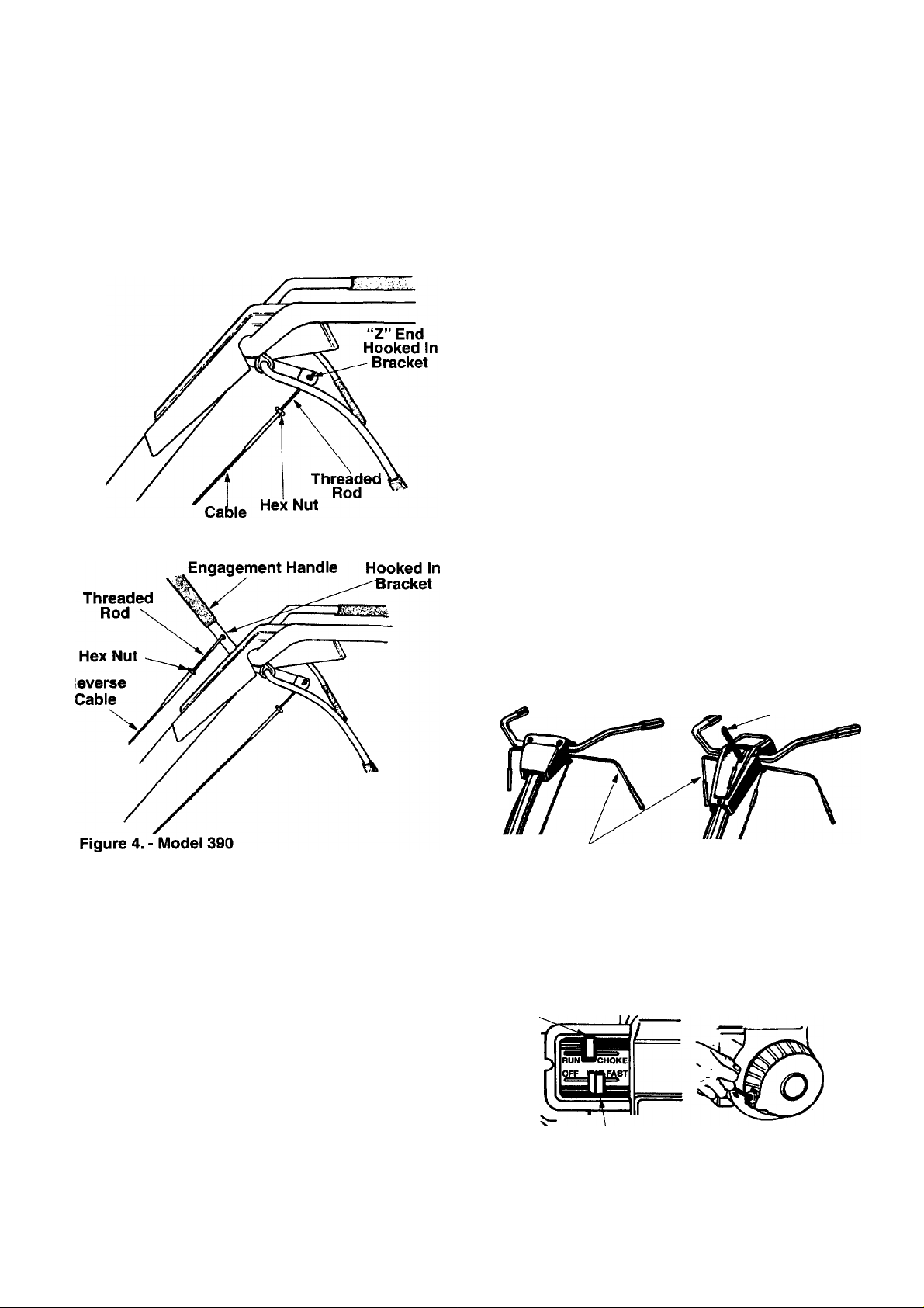
1. Loosen the hex nut on the threaded rod near the
end of the cable, and move it up the rod as far as it
will go.
2. Unthread the rod from the rest of the cable. Hook
the “Z” end of the rod into the bracket underneath
the handle assembly from the right hand side.
(See Figure 3)
Page 5
3. Thread the rod back into the cable until the cable
is straight. Do not tighten it enough to put any ten
sion on the spring.
4. Thread the hex nut down against the end of cable.
Use a pair of pliers and a wrench to lock the nut
against the rod.
NOTE: Do not overtighten control cable. Too much
tension may cause it to break when engaged.
Figure 3. - Model 340
Reverse Tine
‘Z” End
REVERSE CABLE (Model 390 Only)
The reverse clutch cable is the cable which is attached
closer to the front of the tiller. Attach the end of the
reverse cable to the reverse tine drive clutch lever,
above the handle assembly, in the same manner as
you attached the forward cable. (See Figure 4)
FINAL CLUTCH ADJUSTMENT
To check the clutch cable adjustment, proceed as
follows.
1. Disconnect the spark plug wire and move it away
from the spark plug to prevent accidental starting.
2. Engage and release the tine engagement handle,
then the reverse tine engagement lever (model
390 only). If an excessive noise is heard when
releasing either the tine drive clutch handle or
lever, the cable may be too loose. Adjust either the
forward or reverse clutch cable by loosening the
hex nut, threading the rod into the cable one or
two turns, then retightening the nut.
3. With tine engagement handle in neutral (released)
as shown in figure 5, pull the starter rope several
times. The tines should not turn. If they turn for
ward, loosen the hex nut on the forward cable
(underneath the handle assembly). If they turn
toward the rear (model 390 only), loosen the hex
nut on the reverse cable (above the handle
assembly). Unthread the rod from the cable 2 or 3
turns. Retighten the hex nut, and check again for
correct adjustment.
CONTROLS
THROHLE CONTROL
The throttle control lever is located on the engine. It
controls the engine speed and stops the engine. (See
Figure 6)
Model 340
Tine
Engagement Handle
Figure 5.
Choke
Throttle Control
Figure 6.
Reverse Tine
Engagement Handle
Model 390
Page 6

CHOKE LEVER
The choke lever is located above the throttle (ontrol. It
is used to enrich the fuel mixture when startir g a cold
engine.
FORWARD TINE ENGAGEMENT HANDLE
The forward tine engagement handle is located
beneath the tiller handle. (See Figure 5) Sc ueezing
the handle up against the tiller handle engages the
tines. Release the handle to stop the tines.
(DPERATION
REVERSE TINE DRIVE CLUTCH LEVER
(Model 390 Only)
The reverse tine drive clutch lever is located on top of
the handle panel. (See Figure 5) Pull the lever to the
rear to move the tines in reverse. Release the lever to
stop the reverse tine drive.
NOTE: Never engage both the forward and reverse
tine drives at the same time. Engaging both forward
and reverse tine drives at the same time could dam
age the belt drives and cause the engine to stall.
DEPTH STAKE
The depth stake controls the tilling depth. Refer to
"How to Use Your Tiller" section on page 6.
GAS AND OIL FILL-UP
Service the engine with gasoline and oil as instructed
in the separate engine manual packed with your tiller.
Read instructions carefully.
NOTE: Your tiller is shipped without oil; however, a
small amount of oil may be present from the fe ctory.
TO START ENGINE
WARNING: BE SURE NO ONE IS STAND
ING IN FRONT OFTHE TILLER WHILE THE
A
1. Attach spark plug wire to spark plug. Mako certain
2. Make certain all controls are in the neutral position
3. Place the throttle control lever in FAST position.
4. Move choke lever to CHOKE position. (\ warm
5. Grasp starter handle (See Figure 6) and pull rope
6. Pull rope with a rapid, continuous, full arn stroke.
7. Repeat preceding instructions 5 and 6 unti engine
8. Move throttle control to IDLE position fcr a few
ENGINE IS RUNNING OR BEING
STARTED.
the metal loop on the end of the spark p ug wire
(inside the boot) is fastened securely over the
metal tip on the spark plug.
(released). (See Figure 5)
(See Figure 6)
engine requires little or no choke.)
out slowly until engine reaches start of compres
sion cycle (rope will pull slightly harder at this
point). Let the rope rewind slowly.
Keep a firm grip on starter handle. Let rop(! rewind
slowly. Do not let starter handle snap back against
starter.
starts. When engine starts, move choke ever on
engine halfway between CHOKE and RUh .
minutes warm-up. Move choke lever to RL N posi
tion as engine warms up.
TO STOP ENGINE
1. Move throttle control lever to OFF position.
2. Disconnect spark plug wire from spark plug and
ground against the engine to prevent accidental
starting while equipment is unattended.
HOW TO USE YOUR TILLER
Your tiller is a precision built machine designed for
seed bed preparation, cultivating, furrowing and
mulching. It is engineered to minimize the hardest
work in the vegetable or flower garden, to till the soil
for planting and cultivating, and to perform many other
useful labor saving tasks in the garden. With the
proper amount of care and maintenance, this machine
will provide the owner with many years of service.
WHEEL POSITION
The tiller is shipped with the wheels adjusted such that
the unit sits level. While tilling, as the tines enter the
ground and the front of the tiller lowers, the wheels
must be raised to level the unit, which is essential for
proper engine operation. This adjustment is made by
removing the clevis pin and hairpin clip from wheel
yoke, raising the wheels to the desired height, and
replacing the clevis pin and hairpin clip. (See Figure 7)
Wheel
Yoke
Page 7

DONTROLLING SPEED AND TILLING DEPTH
1. Wheel Yoke Adjustment: Place wheel yoke so
that the wheels are forward (nearest point
between wheels and tines) for shallow tilling, culti
vating and transport. The forward speed will
increase. Turn yoke around (farthest point
between wheels and tines) for deep tilling. For
ward speed will decrease. (See Figure 8)
When tilling, leave approximately 8 inches of unfilled
soil between the first and second tilling paths, then
make the third path between the first and second as
shown in figure 10. In some soils, the desired depth is
obtained the first time over the garden. In other soils,
the desired depth is obtained by going over the garden
two or three times. In the latter case, the depth stake
should be lowered before each succeeding pass over
the garden. Passes should be made across the length
and width of the garden alternately. Rocks which are
turned up should be removed from the garden area.
2. Depth Stake Adjustment: The depth stake acts
as a brake for the tiller and controls the depth and
speed at which the machine will operate. Remove
the clevis pin and hairpin clip to raise or lower
depth stake. (See Figure 7)
By increasing the depth of the depth stake, the forward
speed of the machine is reduced, and the working
depth is increased. (See Figure 9) When the depth
stake is raised, the working depth of the machine is
reduced and the forward speed is increased. The
working depth of the machine may be predetermined
by setting the depth stake and wheels so that the
wheels are about four inches from the ground when
the tines and depth stake are resting on the ground.
This setting will permit a working depth of about four
inches. When presetting the working depth, the han
dles should be adjusted so the hand grips are a little
above waist height because the tiller will be lower
when the tines and depth stake penetrate the ground.
Figure 10.
3. Handle Pressure: Further control of tilling depth
and travel speed can be obtained by variation of
pressure on the handles. A downward pressure
on the handles will reduce the working depth and
increase the forward speed. An upward pressure
on the handles will increase the working depth
and reduce the forward speed. The type of soil
and working conditions will determine the actual
setting of the depth stake and the handle pressure
required.
4. Throttle Control: The throttle control lever adjusts
the engine speed and stops the engine. With the
throttle control lever pushed completely forward,
the carburetor is in START position. Pulling the
throttle control back slightly adjusts the engine
speed to FAST. Pulling the throttle back further
Page 8

reduces the engine speed to SLOW. Pull the
throttle completely back to stop the engir e.
Use maximum engine speed for deep tilling. Move
the throttle control to SLOW when transporting the
tiller.
TRANSPORTING THE TILLER
To transport the tiller to or from the garden, pivot the
depth stake forward, out of the way. See figu e 9. With
the throttle control in SLOW position, the unit will walk
freely on top of the lawn. If the operator does not allow
the tiller to move freely, the unit will start o till the
surface.
CULTIVATING
For cultivating, a two to three inch depth is desirable.
Setting the wheels and depth stake so that the wheels
are about two inches above the ground while the tiller
is resting on the tines and depth stake will allow the
machine to work at cultivating depth. Th(! throttle
should be set to control forward movement o a slow
walking speed. With the outer tines installed, he work
ing width of the machine is 22 or 24 inches. For culti
vation, this may be reduced to 13 inches by emoving
the outer tines. Refer to Tine Width Adjustment in
Adjustment section. When laying out plant rows, be
sure to allow enough width to permit cultivation
between the rows. In growing corn or similar crops,
check-row planting will permit cross cultivé tion and
practically eliminate hand hoeing. (See Figur a 11)
Figure 11.
The tiller has many uses other than tilling and cultivat
ing a garden. One of these is the preparation of lawn
area for seeding. The tiller will prepare a deep seed
bed which will be free of hard unfilled spots, allowing a
better stand of grass to grow. The tiller is very useful
for loosening hard soil for excavation with a shovel. No
tedious hand pickwork will be necessary. Your tiller
may be used for mixing compost in the pile, or for mix
ing it with the soil in your garden. This should be done
after the soil has been broken to the full working depth.
The compost should be worked in to a depth of six to
seven inches. This may be done by working the length
of the garden, and then by making separate passes
across its width. The addition of decayed organic mat
ter will substantially increase the fertility of your gar
den. For proper decaying action, fertilizer should be
applied and worked in with the mulch materials. Break
ing up leaves and straw and mixing it with several
inches of soil causes the soil to hold moisture longer
and allows proper aeration of the plant root system.
This also retards the growth of weeds.
The U.S. Department of Agriculture and various state
and local agencies offer published booklets and expert
advice on all phases of gardening. They should be
consulted regarding soil information, planting dates,
and the most satisfactory varieties of crop for your par
ticular area.
ADJUSTMENTS
WARNING: Disconnect the spark plug
wire and ground against the engine
A
WHEEL ADJUSTMENTS
To adjust the wheel yoke and wheel position, refer to
"How To Use Your Tiller," on page 6.
DEPTH STAKE ADJUSTMENT
To adjust the depth stake, refer to "How To Use Your
Tiller" on page 6.
before performing any adjustments,
repairs, or maintenance.
TINE WIDTH ADJUSTMENT
The tilling width of the unit is 22 inches. (See figure
12) Tilling width can be increased to 24 inches by
removing the clevis pins and hairpin clips, sliding the
outer tines out one inch, and securing in this position
with the clevis pins and hairpin clips. (See Figure 13)
For cultivation, reduce the tine width to 13 inches by
removing the outer tines completely. (See Figure 14)
Page 9

Figure 12.
Figure 13.
CLUTCH CONTROL ADJUSTMENTS
To adjust the clutch controls, refer to the Final Adjust
ment section of assembly instructions.
CARBURETOR ADJUSTMENT
WARNING: If any adjustments are made to
the engine while the engine is running
A
Minor carburetor adjustment may be required to com
pensate for differences in fuel, temperature, altitude or
load. If adjustments are needed, refer to the engine
manual packed with the tiller.
NOTE: A dirty air cleaner will cause engine to run
rough. Be certain air cleaner is clean and attached to
the carburetor before adjusting carburetor. Do not
make unnecessary adjustments. Factory settings are
satisfactory for most applications and conditions.
(e.g. carburetor), disengage all clutches
and tines. Keep clear of all moving parts.
Be careful of heated surfaces and muffler.
Figure 14.
LUBRICATION
WARNING: Always stop engine and dis
connect spark plug wire before cleaning,
A
lubricating or doing any kind of work on
tiller.
MAINTENANCE
WARNING: Disconnect spark plug wire
and ground it against the engine before
A
TROUBLE SHOOTING
Refer to page 12 of this manual for trouble shooting
information.
ENGINE
Refer to the separate engine manual for all engine
maintenance instructions.
Maintain engine oil as instructed in the separate
engine manual packed with your unit. Read and follow
instructions carefully.
Service air cleaner every 25 hours under normal con
ditions. Clean every few hours under extremely dusty
performing any repairs or maintenance.
Pivot Points-Remove the belt cover and lubricate all
moving parts and pivot points at least once a season
using SAE 30 engine oil.
Chain Drive-The chain case is pre-lubricated and
sealed at the factory.
conditions. Poor engine performance and flooding
usually indicates that the air cleaner should be
serviced. To service the air cleaner, refer to the sepa
rate engine manual packed with your unit.
IMPORTANT: Never run your engine without air
cleaner completely assembled.
The spark plug should be cleaned and the gap reset
once a season. Spark plug replacement is recom
mended at the start of each tilling season; check
engine manual for correct plug type and gap specifica
tions.
Clean the engine regularly with a cloth or brush.
Keep the cooling system (blower housing area) clean
to permit proper air circulation which is essential to
engine performance and life. Be certain to remove all
dirt and combustible debris from muffler area.
Page 10

CLEANING THE TINE AREA
Clean the underside of the tine shield after ea:h use.
The dirt washes off the tines easier if was ied off
immediately instead of after it dries.
BELT REMOVAL AND REPLACEMENT
Your tiller has been engineered with belts rrade of
special material (Kevlar Tensile). They should not be
replaced with an off-the-shelf belt. If belt repla :ement
is required, order belt or belts by part numbor from
your nearest authorized service dealer.
Forward Drive Belt- Part No. 754-0428
Reverse Drive Belt- Part No. 754-0^ 29
(Model 390 Only)
Reverse Drive Belt (Model 390 Only)
1. Disconnect and ground the spark plug wire
against the engine. Remove the belt covor from
the left side of the tiller as follows.
2. Remove two self-tapping screws and flat w ashers
from the front of belt cover. (See Figure 151
3. Remove the hex stop nut and flat washer from the
side of the belt cover. Remove belt cover.
6. Reassemble the new belt, following instructions in
reverse order. Make certain the reverse drive belt
is assembled with the wide side of the belt against
the transmission and engine pulleys. Be certain to
adjust the clutch control as instructed in the final
clutch adjustment section of assembly instructions
Transmission
Nut
Figure 17. Model 390 Shown
Belt
iover
4. Lift the belt off the transmission pulley.
5. Remove the hex nut which secures the leverse
idler pulley to the idler bracket. Slide idlet pulley
out and remove the belt. (See Figure 16)
Reverse Idler Pulley
Forward
Belt
Hex Nut
Forward Drive Belt (See Figure 16)
1. Model 340: Remove the belt cover by following
steps 1 and 2 of the previous section.
Model 390; Remove the reverse drive belt as
instructed in the previous section.
2. Remove the belt keeper from the idler pulley by
removing the idler pulley nut.
3. Lift belt off the idler pulley and transmission pulley.
See figure 17.
4. Using a 9/16" wrench, remove bolt from engine
pulley. See figure 17.
5. Push reverse idler pulley bracket forward, and
remove engine pulley and belt. See figure 17.
6. Reassemble the new belt, following instructions in
reverse order. Make certain the forward drive belt
is assembled with the wide side of the belt away
from the transmission and engine pulleys. Be cer
tain to adjust the clutch control as instructed in the
final clutch adjustment section of assembly
instructions.
Reverse Belt ^ „■ ■ ■
Transmission
Figure 16. Model 390 Shown Pulley
10
Page 11

OFF-SEASON STORAGE
If the tiller is to be inoperative for a period longer than
30 days, the following precautions are recommended.
1. Working outdoors, drain all fuel from the fuel tank.
Run the engine until it stops from lack of fuel.
WARNING: DO NOT DRAIN FUEL WHILE
A
2. Drain all the oil from the crankcase (this should be
3. Protect the inside of the engine for storage as
4. Clean the engine and the entire tiller thoroughly.
5. Wipe tines with oiled rag to prevent rust.
NOTE: When storing any type of power equipment in
an unventilated or metal storage shed, care should be
taken to rustproof the equipment. Using a light oil or
silicone, coat the equipment, especially any springs,
bearings and cables.
SMOKING, OR IF NEAR AN OPEN FIRE.
done after the engine has been operated and is
still warm) and refill the crankcase with fresh oil.
instructed in the separate engine manual packed
with your tiller.
6. Store in a clean, dry area. Do not store next to
corrosive materials, such as fertilizer.
11
Page 12

TROUBLE SHOOTING GUIDE
Trouble
Engine fails to start
Engine runs erratic
Engine overheats
Tines do not engage
Possible Cause(s)
1. Fuel tank empty, or stale fuel.
2. Throttle control lover not in correct
starting position.
3. Blocked fuel line
4. Spark piug wire disconnected.
5. Faulty spark pluc.
6. Engine flooded.
1. Unit running on (iHOKE.
2. Spark piug wire loose.
3. Blocked fuel line or stale fuel.
4. Vent in gas cap plugged.
5. Water or dirt in fuel system.
6. Dirty air cleaner.
7. Carburetor out o adjustment.
1. Engine oil level low.
2. Air flow restricted.
3. Carburetor not adjusted properly.
1. Foreign object lodged in tines.
2. Tine clevis pin(sj missing.
3. Control cable no adjusted properly.
4. Belt worn and/or stretched.
Corrective Action
1. Fill tank with clean, fresh gasoline.
2. Move throttle lever to start position.
3. Clean fuel line.
4. Connect wire to spark plug.
5. Clean, adjust gap or replace.
6. Crank engine with throttle in FAST
position.
1. Move choke lever to OFF position.
2. Connect and tighten spark plug wire.
3. Clean fuel line; fill tank with clean,
fresh gasoline.
4. Clear vent.
5. Drain fuel tank. Refill with fresh fuel.
6. Clean air cleaner as instructed in
separate engine manual.
7. Adjust carburetor as instructed in
separate engine manual.
1. Fill crankcase with proper oil.
2. Remove blower housing and clean as
instructed in separate engine manual.
3. Adjust carburetor as instructed in
separate engine manual.
1. Dislodge foreign object.
2. Replace tine clevis pin(s).
3. Adjust control cable (see assembly
instructions).
4. Replace belt.
NOTE: For repairs beyond the minor adjustments lii ted above, please contact your local service dealer.
12
Page 13

Page 14

Page 15

A
TILLER
ASSORTED
PARTS
LIST
Engine Oil (SAE 30)
Part No. 737-0208
Forward Drive Clutch Cable
For Model 340; Part No. 746-0918
Reverse Drive Clutch Cable
For Model 340: N/A
For Model 390: Part No. 746-0919
Forward Drive Belt
For Model 340 and
Part No. 754-0428
Reverse Drive Belt
For Model 340: N/A
For Model 390; Part No. 754-0429
iJl
Air Filter
For Model 340 and 390
Part No. 491588
Air Pre-Cleaner
For Model 340 and 390
Part No. 491435
Spark Plug
PartNo.RJ19LM
Forward Idler Pulley For
Model 340: Part No. 756-0313
For Model 390: Part No. 756-0313
Reverse Idler Pulley For
Model 340: N/A
For Model 390: Part No. 756-0199
Illustrated Parts Manual
PartNo.770-97-6A
Page 16

For Parts, Acce
ssories or Service Information,
Call 1-
800-800-7310
Model Number
□ □ □ □ □ □ □ □ □ □ a
Serial Number
□ □ □ □ □ □ □ □ □ □ a
Product Number
May not fill all the above spaces
The only way to ensure the performance of your
product is to use original equipment parts and
accessories. MTD designs and engineers quality
parts to exacting specifications. When you
substitute, you take a chance on quality,
reliability, safety and performance. Use MTD
original equipment,
the best buy on the American Landscape.
-American Made American Owned -
\A/ARMIMO' Engine Exhaust from this product contains chemicals known to the
WMlil NI IN vJ. of CcJifornia to cause cancer, birth defects or other reproductive harm.
a
 Loading...