

Page 1
OPERATOR’S MANUAL
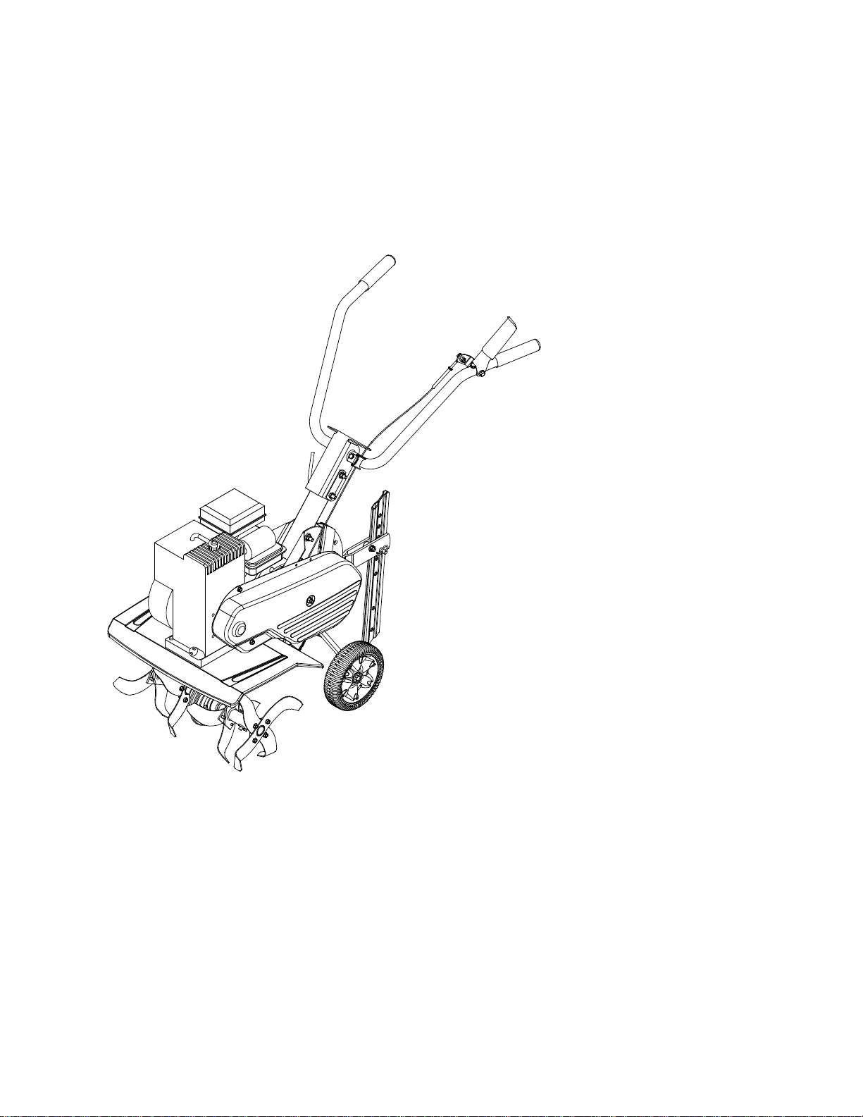
Front Tine Tiller
Model Series
300 & 330
IMPORTANT: READ SAFETY RULES AND INSTRUCTIONS CAREFULLY
Warning:
covered, brush-covered or grass-covered land unless the engine’s exhaust system is equipped with a spark arrester meeting
applicable local or state laws (if any). If a spark arrester is used, it should be maintained in effective working order by the operator.
In the State of California the above is required by law (Section 4442 of the California Public Resources Code). Other states may have
similar laws. Federal laws apply on federal lands. A spark arrester for the muffler is available through your nearest engine authorized
service dealer or contact the service department, P.O. Box 361131 Cleveland, Ohio 44136-0019.
This unit is equipped with an internal combustion engine and should not be used on or near any unimproved forest-
MTD LLC, P.O. BOX 361131 CLEVELAND, OHIO 44136-0019
PRINTED IN U.S.A.
FORM NO.
770-10564B.fm
(12/2002)
Page 2

TABLE OF CONTENTS
Content Page
Important Safe Operation Practices...................................................................3
Assembling Your Tiller.......................................................................................5
Know Your Tiller.................................................................................................6
Operating Your Tiller..........................................................................................7
Making Adjustments ..........................................................................................9
Maintaining Your Tiller .......................................................................................10
Troubleshooting.................................................................................................12
Parts List............................................................................................................14
FINDING MODEL NUMBER
This Operator’s Manual is an important part of your new Tiller. It will help you assemble, prepare and
maintain the unit for best performance. Please read and understand what it says.
Before you start assembling your new equipme nt, please locate the model plate on the
equipment and copy the information from it in the space provided below. The information on
the model plate is very important if you need help from our Customer Support Department or
an authorized dealer.
• You can locate the model number by standing in the operating position behind the unit and looking
down at the center of the rear tine cover. A sample model plate is explained below. For future
reference, please copy the model number and the serial number of the equipment in the space below.
Copy the model number here:
MTD LLC
www.mtdproducts.com
P. O. BOX
CLEVELAND,OH
330-220-4683
800-800-7310
361131
44136
Copy the serial number here:
ENGINE INFORMATION
The engine manufacturer is responsible for all engine-related issues with regards to performance, powerrating, specifications, warranty and service. Please refer to the engine manufacturer’s Owner’s/Operator’s
Manual packed separately with your unit for more information.
CONTACTING CUSTOMER SUPPORT
If you have difficulty assembling this product or have any questions regarding the controls, operation or
maintenance of this unit, please call Customer Support Department.
Call 1- (330) 220-4MTD (4683) or 1- (800)-800-7310 to reach a Customer Support
representative. Please have your unit’s model number and serial number ready when you
call. See previous section to locate this information. You will be asked to enter the serial
number in order to process your call.
For more details about your unit, visit our website at www.mtdproducts.com
2
Page 3

SECTION 1: IMPORTANT SAFE OPERATION PRACTICES
WARNING:
This symbol points out important safety instructions which, if not followed, could
endanger the personal safety and/or property of yourself and others. Read and follow all instructions in
this manual before attempting to operate this machine. Fa ilure to comply with thes e instructions may
result in per sonal in jury. When you see thi s symbol — heed its warn ing.
WARNING:
Engine exhaust, some of i ts constituents, and certain vehicle components contain or
emit chemicals known to State of California to cause ca ncer and birth defects or other rep roductive
harm.
DANGER:
This machine was built to be operated according to the rules for safe operation in this
manual. As with any type of power equipment, carelessness or error on the part of the operator can
result in serious injury. This machine is capable of amputating hands and feet. Failure to observe the
following safety instructions could result in serious injury or death.
Training
1. Read, understand, and follow all instructions on the
machine and in the manual(s) before attempting to
assemble and operate. Keep this manual in a s afe
place for future and regular reference and for
ordering replacement parts.
2. Be familiar with all controls and their proper
operation. Know how to stop the machine and
disengage them quickly.
3. Never allow children under 14 years old to oper ate
this machine. Children 14 years old and over should
read and understand the operation instructions and
safety rules in this manual and should be tr ained
and supervised by a parent.
4. Never allow adults to operate this machine without
proper instruction.
5. Keep bystanders, helpers, pets and children at least
75 feet from the machine while it is in operati on.
Stop machine if anyone enters the area.
7. Use only an approved gasoline container.
8. Extinguish all cigarettes, cigars, pipes and other
sources of ignition.
9. Never fuel machine indoors.
10. Never remove gas cap or add fuel while the engine
is hot or running.
11. Allow engine to cool at least two minutes before
refueling.
12. Never over fill fuel tank. Fill tank to no more than ½
inch below bottom of filler neck to provide space for
fuel expansion.
13. Replace gasoline cap and tighten securely.
14. If gasoline is spilled, wipe it off the engine and
equipment. Move machine to another area. Wait 5
minutes before starting the engine.
15. Never store the machine or fuel container inside
near an open flame, spark or pilot light (e.g.
furnace, water or space heater, clothes dryer etc.).
16. Allow machine to cool 5 minutes before storing.
Preparation
1. Thoroughly inspect the area where the equipment is
to be used. Remove all stones, sticks, wire, and
other foreign objects which could be tripped over
and cause personal injury.
2. Wear sturdy, rough-soled work shoes and close
fitting slacks and shirt. Loose fitting clothes or
jewelry can be caught in movable parts. Never
operate this machine in bare feet or sandals.
3. Disengage clutch levers and shift (if provided) into
neutral (“N”) before starting the engine.
4. Never leave this machine unattended with the
engine running.
5. Never attempt to make any adjustments while
engine is running, except where specifically
recommended in the operator’s manual.
6. To avoid personal injury or property damage use
extreme care in handling gasoline. Gasoli ne is
extremely flammable and the vapors are explosive.
Serious personal injury can occur when gasoline is
spilled on yourself or your clothes which can igni te.
Wash your skin and change clothes immediately.
Operation
1. Do not put hands or feet near rotating parts. Contact
with the rotating parts can amputate hands and feet.
2. Do not operate machine while under the influence
of alcohol or drugs.
3. Never operate this machine without good visibility
or light. Always be sure of your footing and keep a
firm hold on the handles.
4. Keep bystanders, helpers, pets, and children at
least 75 feet from the machine while it is in
operation. Stop the machine if anyone enters the
area.
5. Be careful when tilling in hard ground. The tines
may catch in the ground and propel the tiller
forward. If this occurs, let go of the handle bars and
do not restrain the machine.
6. Exercise extreme caution when operating on or
crossing gravel surfaces. Stay alert for hidden
hazards or traffic. Do not carry passengers.
7. Never operate the machine at high transport
speeds on hard or slippery surfaces.
8. Exercise caution to avoid slipping or falling.
3
Page 4
9. Look down and behind and use care when in
reverse or pulling machine towards you.
10. Start the engine according to the instructions found
in this manual and keep feet well away from the
tines at all times.
11. After striking a foreign object, stop the engine,
disconnect the spark plug wire and ground against
the engine. Thoroughly inspect the machine for any
damage. Repair the damage before starting and
operating.
12. Disengage all clutch levers and stop engine before
you leave the operating position (behind the
handles). Wait until the tines come to a comple te
stop before unclogging the tines, making any
adjustments, or inspections.
13. Never run an engine indoors or in a poorly
ventilated area. Engine exhaust contains carbon
monoxide, an odorless and deadly gas.
14. Muffler and engine become hot and can cause a
burn. Do not touch.
15. Use caution when tilling near fences, buildings and
underground utilities. Rotating tines can cause
property damage or personal injury.
16. Do not overload machine capacity by attempting to
till soil to deep at to fast of a rate.
17. If the machine should start making an unusual noise
or vibration, stop the engine, disconnect the spark
plug wire and ground it against the engine. Inspect
thoroughly for damage. Repair any damage before
starting and operating.
18. Keep all shields, guards and safety devices in place
and operating properly.
19. Never pick up or carry machine while the engine is
running.
20. Use only attachments and accessories approved by
the manufacturer. Failure to do so, can result in
personal injury.
21. If situations occur which are not covered in this
manual, use care and good judgment. Contact your
dealer or telephone 1-800-800-7310 for assistance
and the name of your nearest servicing dealer.
4. Do not change the engine governor settings or overspeed the engine. The governor controls the
maximum safe operating speed of the engine.
5. Maintain or replace safety and instruction labels, as
necessary.
6. Follow this manual for safe loading, unloading,
transporting, and storage of this machine.
7. Never store the machine or fuel container inside
where there is an open flame, spark or pilot li ght
such as a water heater, furnace, clothes dryer etc.
8. Always refer to the operator’s manual for proper
instructions on off-season storage.
9. If the fuel tank has to be drained, do this outdoors.
10. Observe proper disposal laws and regulations for
gas, oil, etc. to protect the environment.
Y our Responsibility
1. Restrict the use of this power machine to persons
who read, understand and follow the warnings and
instructions in this manual and on the ma chine.
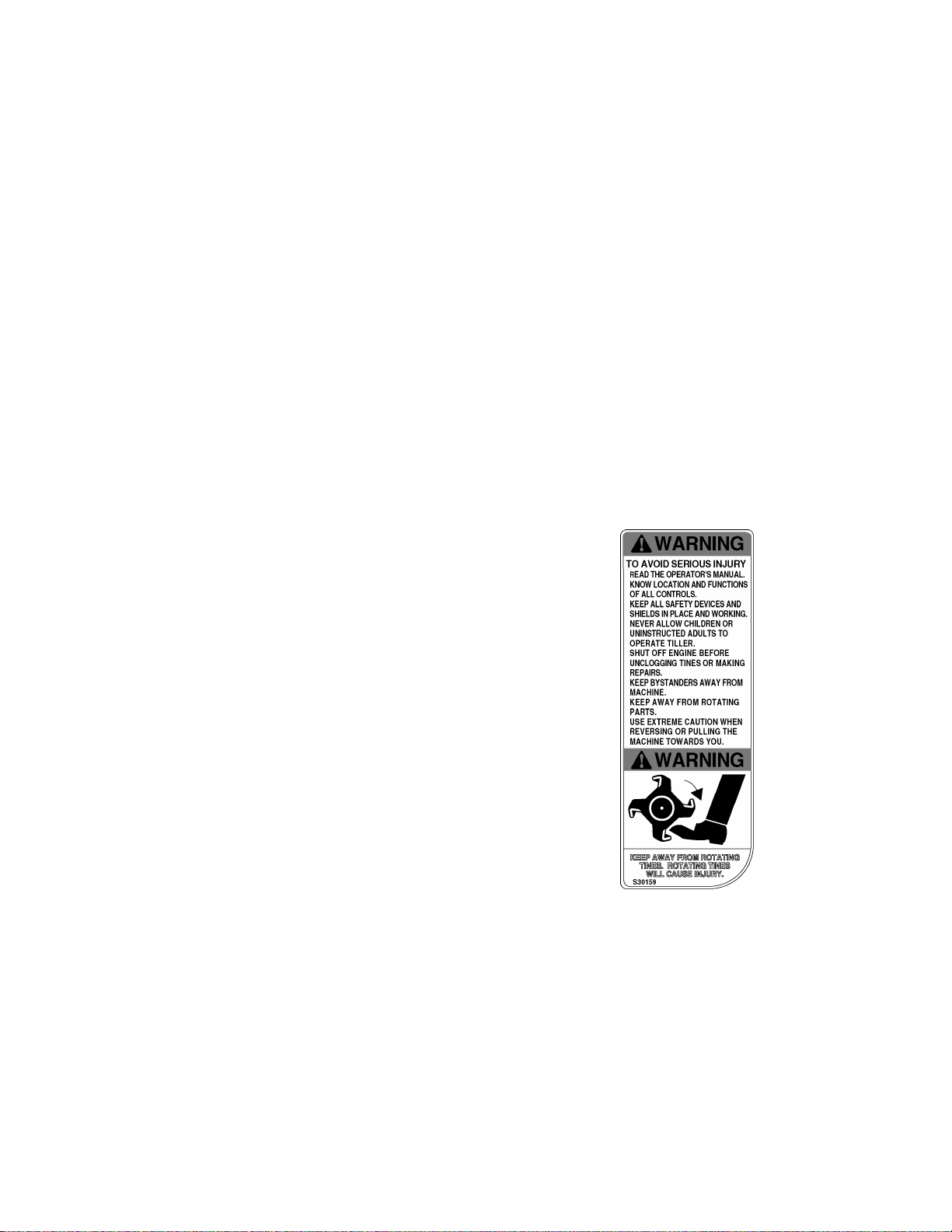
2. The safety label on the tiller is reproduced below for
your review. To ensure safe operation of the tiller,
follow the instructions on all labels c losely.
Maintenance & Storage
1. Never tamper with safety devices. Check their
proper operation regularly.
2. Check bolts and screws for proper tightness at
frequent intervals to keep the machine in safe
working condition. Also, visually inspect machi ne for
any damage.
3. Before cleaning, repairing, or inspecting, stop the
engine and make certain the tines and all moving
parts have stopped. Disconnect the spark plug wire
and ground it against the engine to prevent
unintended starting.
4
Page 5
SECTION 2: ASSEMBLING YOUR TILLER
NOTE:
of tillers. The units illustrated may vary slightly from
your unit. Follow onl y those instructions whic h pertain
to your model number.
NOTE:
determined from behind the unit in the operating
position.
This operator’s manual covers various models
References to right or l eft si de of t he tiller a re
T o Remove Unit From Carton
• Remove staples, break glue on top flaps, or cut
tape at carton end and peel along top flap to open
carton.
• Remove loose parts included with unit (i.e.,
operator’s manual, etc.).
• Cut corners and lay carton down flat.
• Remove packing material.
• Roll or slide unit out of cart on. C heck c arton
thoroughly for loose parts.
• Extend control cable and lay on the floor. Be careful
not to bend or kink control cable.
IMPORT ANT :
in the engine. Be certain to service engine with gasoline
and oil as instructed in the separate engine manual
before operating your machine.
This unit is shipped without gasoline or oil
Handle
Adjustment Lever
Handle
Adjustment Lever
Loose Parts In Carton
Tailpiece and Depth Stake
NOTE:
to the loose parts or the tiller.
All hardware needed for assembly is attached
Before Assembly
WARNING:
wire and ground it against the engine to
prevent unintended starting.
Disconnect the spark plug
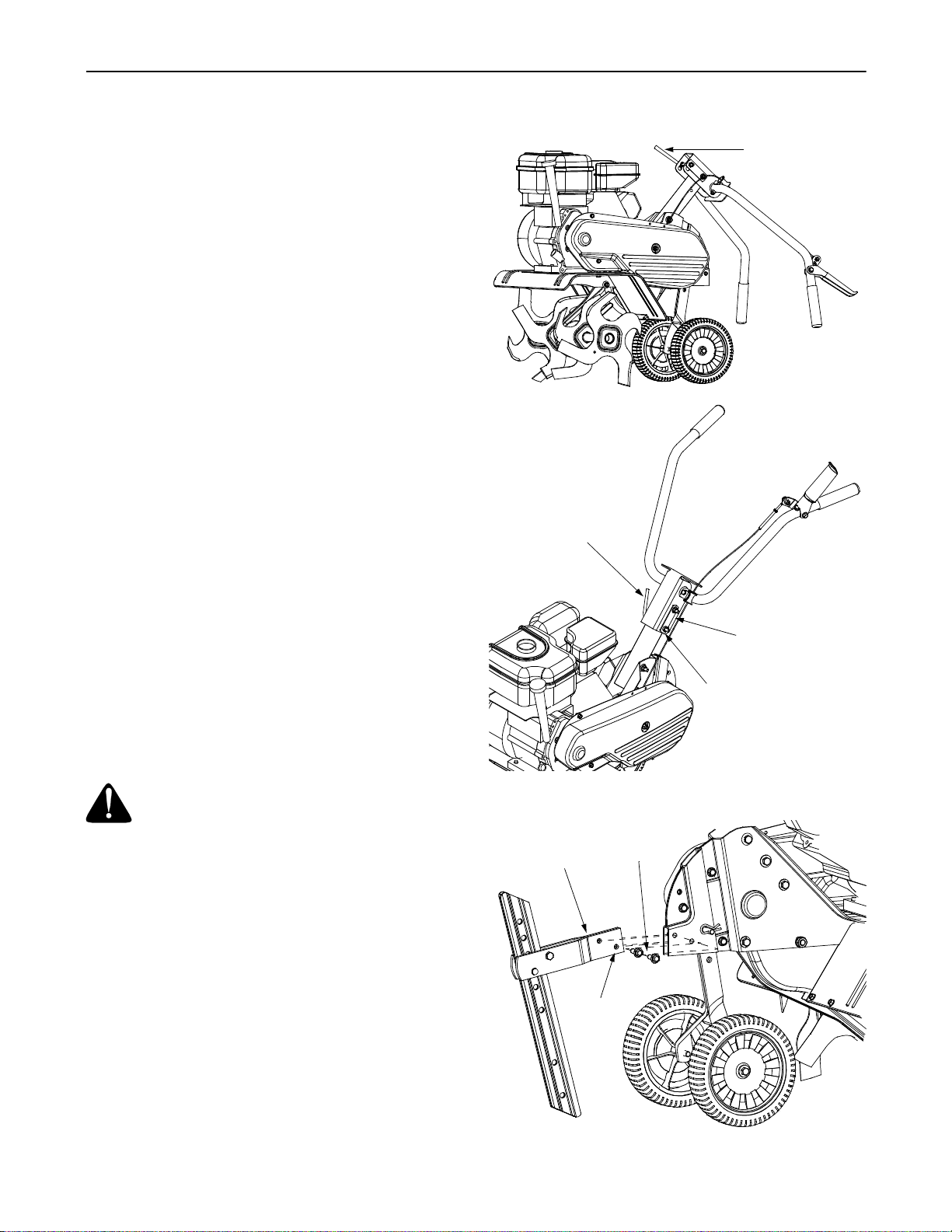
Assembling The Handle
• Remove the handle adjustment lever from handle
and lift up upper handle to raise in operating
position. See Figu re 1.
• Reinsert adjustment lever through the lower hole,
tightening the lever into lock nut on the retainer
bracket.
• Once the lever is in the lock nut, the handle can be
moved to the desired position and then tighten
securely.
Attaching Tailpiece and Depth Stake
• Remove the two self-tapping screws on the frame
and slide the tailpiece into the frame, with the lower
hole in the tailpiece toward the front. See Figure 2.
• Secure tailpiece with the screws just removed.
Retainer Bracket
Lock Nut
Figure 1
Self-Tapping
Tailpiece
5
Screws
Lower Hole
Figure 2
Page 6
Check Cable Adjustment
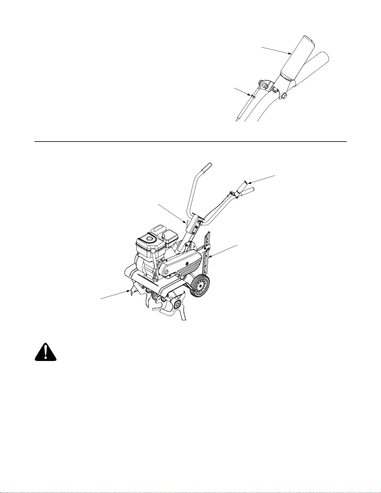
• With the clutch lever disengaged, pull starter rope
slowly several times. The tines should not turn. If
they turn, the cable is not adjusted properly.
• To adjust the cable, loosen the nut near the top of
the cable and unscrew the cable to provide
additional slack in wire. See Figure 3.
• Tighten the nut and check again for proper
adjustment.
SECTION 3: KNOW YOUR TILLER
Handle Adjustment Lever
Clutch Lever
Loosen Nut
Figure 3
Tine Clutch Control
Tines
WARNING:
follow all instructions and warnings on
the machine and in this manual before
operating.
Read, understand, and
Tine Clutch Contr ol
The clutch control lever is located on the left handle.
Squeezing the lever against the handle engages the
tine drive. Release the lever to stop the tines from
turning. See Figure 4
Depth Stake
The depth stake is located in the rear of the tiller and it
controls the tilling depth. See Figure 4
Depth Stake
Figure 4
Handle Adjustment Lever
The handle may be adjusted to the height desired.
Loosen the handle adjustment lever a few turns and
pivot handle up or down to desired position. Tighten
lock. See Figure 4.
Throttle Control
The throttle control lever is located on the engine. It
controls the engine’s speed and stops the engine.
• With the throttle control pushed completely forward,
the carburet or is in START or FAST posi tion. Us e
maximum engine speed for deep tilling.
• Pull the throttle control back to reduce engine
speed to IDLE. Throttle control should be at IDLE
for transporting the tiller.
• Pull the throttle completely back to stop the engine.
6
Page 7
Choke Lever
The choke lever is located near the throttle control. It is
used to enrich the fuel mixture when starting a cold
engine.
Engine Controls
See the separate engine manual for additional
information and functions of the engine controls.
Starter Handle
The starter handle is located on the engine and is
used to manually start the engine.
SECTION 4: OPERATING YOUR TILLER
WARNING:
follow all instructions and warnings on
the machine and in this manual before
operating.
Before Starting
Gas And Oil Fill-Up
Service the engine with gasoline and oil as instructed in
the separate engine manual packed with your tiller.
Read instructi ons carefu lly.
WARNING:
handling gasoline. Gasoline is extremely
flammable and the vapors are explosive.
Never fuel machine indoors or while the
engine is hot or running.
Starting Engine
WARNING:
in front of the tiller while the engine is
running or being started.
• Attach spark plug wire to spark plug. Make sure the
metal cap on the end of the spark plug is fastened
securely over the metal tip on the spark plug.
• Make sure that the tine clutch control is
disengaged.
• Place the throttle control in the FAST position.
• Move choke lever to CHOKE position. A warm
engine requires little or no choke.
• Grasp starter handle and pull rope out slowly until
engine reaches start of compression cycle (rope
will pull slightly harder at this point). Let the rope
rewind slowly.
• Pull rope with a rapid, continuous, full arm stroke.
Keep a firm grip on starter handle. Let rope rewind
slowly. Do not let starter handle snap back against
starter. Repeat until engine starts.
• When engine starts, move choke lever on engine
halfway between CHOKE and RUN. As the engine
warms up, move the lever to RUN position.
• Refer to engine manual for additional engine
information.
Read, understand, and
Use extreme care when
Be sure no one is standing
7
Stopping Engine
• Move throttle control lever to STOP or OFF
position.
• Disconnect spark plug wire from spark plug and
ground against the engine.
Using Y our Tiller
Your tiller (also known as a cultivator) is a precision
built machine designed for seed bed preparation,
cultivating, furrowing and mulching. It is engineered to
minimize t he ha rdest work in th e vege tabl e or f lowe r
garden, to till the soil for planting and cultivating, and to
perform many other useful labor saving tasks in the
garden.
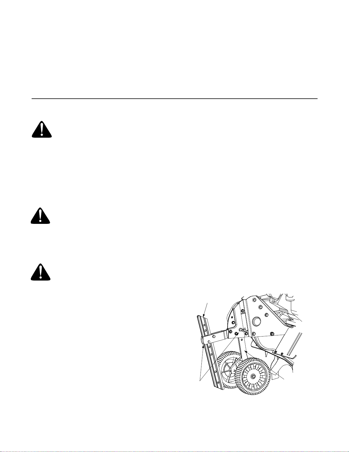
Wheel Position
The tiller is shipped with the wheels adjusted such that
the unit sits level. While tilling, as the tines enter the
ground and the front of the tiller lowers, the wheels
must be raised to level the unit, which is essential for
proper engine operation. This adjustment is made by
removing the clevis pin and hairpin clip from wheel
yoke, raisi ng the wh eels to th e desire d height , and
replacing the clevis pin and hairpin clip. See Figure 5.
Depth Stake
Hairpin Clips
& Clevis Pins
Figure 5
Wheel Yoke
Page 8
Controlling Speed And Tilling Depth
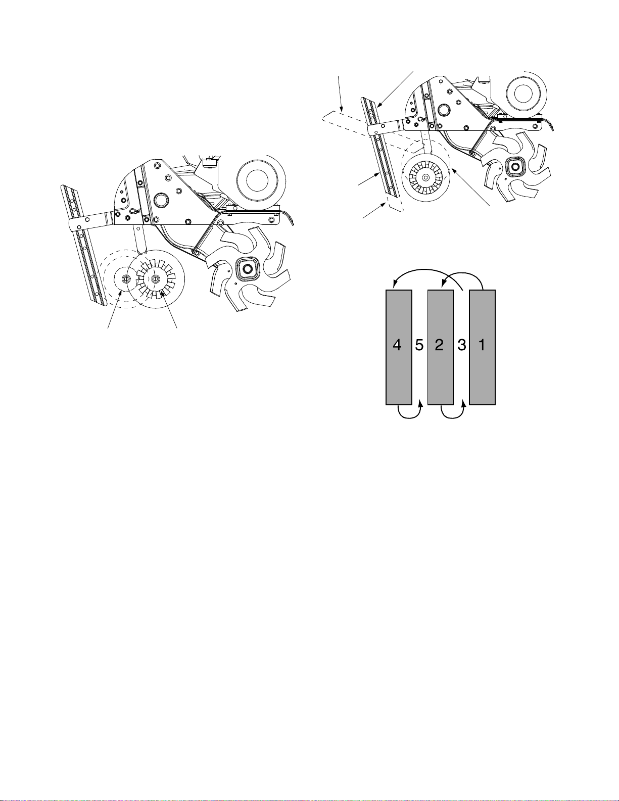
Wheel Yoke Adjustment
Place wheel yoke so that the wheels are forward
(nearest point between wheels and tines) for shallow
tilling, cultivating and transport. The forward speed will
increase. Turn yoke around (farthest point between
wheels and tines) for deep tilling. Forward speed will
decrease. See Figure 6.
Transport
Position
Shallow
Tilling
Deep
Tilling
Depth Stake
Wheel Setting For
Deep Tilling
Figure 7
Position Wheel Yoke
For Deep Tilling
Position Wheel Yoke
For Shallow Tilling
Figure 6
Depth Stake Adjustment
The depth stake acts as a brake for the tiller and
controls the depth and speed at which the machine will
operate. Remove the clevis pin and hairpin clip to raise
or lower depth stake. Refer to Figure 5.
By increasing the depth of the depth stake, the forward
speed of the machine is reduced and the working depth
is increased. When the depth stake is raised, the
working depth of the machine is reduced and the
forward speed is increased. The working depth of the
machine may be predetermined by setting the depth
stake and wheels so that the wheels are about four
inches from the ground when the tines and depth stake
are resting on the ground. This setting will permit a
working depth of about four inches. When presetting
the working depth, the handles should be adjusted so
the hand grips are a little above waist. The tiller will be
lower when the tines and depth stake penetrate the
ground. See Figure 7.
When tilling, leave approximately 8 inches of untilled
soil betw een the fi rst and second tillin g paths , then
make the third path between the first and second. In
some soils, the desired depth is obtained the first time
over the garden. In other soils, the desired depth is
obtained by going over the garden two or three times. In
the latter case, the depth stake should be lowered
before each succeeding pass over the garden. Passes
should be made across the length and width of the
garden alternately. Rocks which are turned up should
be removed from the garden area. See Figure 8.
Figure 8
Handle Pressure
Further control of tilling depth and travel speed can be
obtained by variation of pressure on the handles.
• A downward pressure on the handles will reduce
the working depth and increase the forward speed.
• An upward pressure on the handles will increase
the working depth and reduce the forward speed.
The type of soil and working conditions will determine
the actual setting of the depth stake and the handle
pressure required.
Transporting the Tiller
• To transport the tiller to or from the garden, pivot
the depth stake forward and out of the way. With
the throttle control in SLOW position, the unit will
walk freely on the lawn. If the operator does not
allow the tiller to move freely, the unit will start to till
the surface. Refer to Figure 7.
Cultivating
For cultivating, a two to three inch depth is desirable.
Setting the wheels and depth stake so that the wheels
are about two inches above the ground while the tiller is
resting on the tines and depth stake will allow the
machine to work at cultivating depth. The throttle
should be set to control forward movement to a slow
walking speed. With the outer tines installed, the
8
Page 9
working widt h of t he m achine is 22 or 24 i nches . Fo r
cultivation, this may be reduced to 13 inches by
removing the outer tines. Refer to the Adjustment
Section. Wh en laying ou t plant row s, be sure t o allow
enough width to permit cultivation between the rows. In
growing corn or similar crops, check-row planting will
permit cross cultivation and practically eliminate hand
hoeing. See Figure 9.
Figure 9
SECTION 5: MAKING ADJUSTMENTS
The tiller has many uses other than tilling and
cultivating a garden. One of these is the preparation of
lawn area for seeding. The tiller will prepare a deep
seed bed which will be free of hard untilled spots,
allowing a better stand of grass to grow. The tiller is
very useful for loosening hard soil for excavation with a
shovel. No tedious handwork will be necessary. Your
tiller m ay be us ed fo r mi xing c ompos t in th e pi le, or for
mixing it with the soil in your garden. This should be
done after the soil has been broken to the full working
depth. The compost should be worked in to a depth of
six to seven inches. This may be done by working the
length of the garden and then by making separate
passes across its width. The addition of decayed
organic matter will substantially increase the fertility of
your garden. For proper decaying action, fertilizer
should be applied and worked in with the mulch
materials. Breaking up leaves and straw and mixing it
with several inches of soil causes the soil to hold
moisture longer and allows proper aeration of the plant
root system. This also retards the growth of weeds.
WARNING:
wire and ground it against the engine
before performing any ad justments.
Disconnect the spark plug
Engine Adjustment
Refer to the separate engine manual for engine
adjustment instructions.
Wheel Adjustment
To adjust the wheel yoke and wheel position, refer to
the Operati ng Sectio n.
Depth Stake Adjustment
To adjust the depth stake to a desired position, refer to
the Operati ng Sectio n.
Clutch Control Adjustment
Periodic adjustment of the belt tension may be required
due to normal stretch and wear on the belt. To adjust
the clutch contro l lever, refe r to the Assem bly Section.
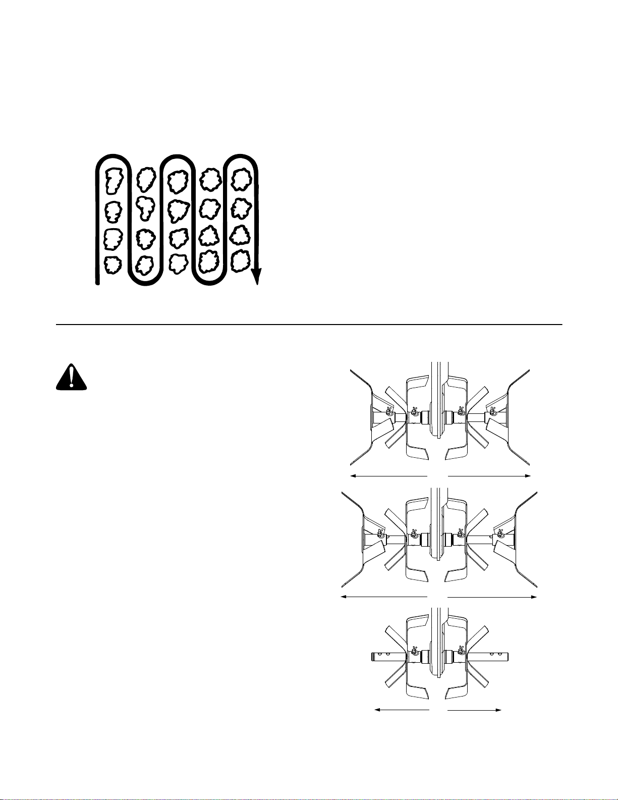
Tine Width Adjustment
The tilling width of the unit is 22 inches. Tilling width can
be increased to 24 inches by removing the clevis pins
and hairpin clips, sliding the outer tines out one inch,
and securing in this position with the clevis pins and
hairpin clips. For cultivation, reduce the tine width to 13
inches by removing the outer tines completely.
See Figure 10
(330 Series Only)
22”
24”
13”
Figure 10
9
Page 10
SECTION 6: MAINTAINING YOUR TILLER
WARNING:
wire and ground it against the engine
before performing any repairs or
maintenance.
Disconnect the spark plug
Engine
Refer to the separate engine manual for engine
maintenance instructions.
Maintain engine oil as instru cted i n the sepa rate
engine manual packed with your unit. Read and follow
instructions carefully.
Service air cleaner every ten hours under normal
conditions. Clean every hour under extremely dusty
conditions. Poor engine performance and flooding
usually indicates that the air cleaner should be
serviced. To service the air cleaner, refer to the
separate engine manual packed with your unit.
IMPORT ANT :
completely as sembled .
The spark plug should be cleaned and the gap reset
every 25 hours of engine operation. Spark plug
replacement is recommended at the start of each tiller
season; check engine manual for correct plug type and
gap specification.
Clean the engine regularly with a cloth or brush. Keep
the cooling system (blower housing area) clean to
permit proper air circulation which is essential to engine
performance and life. Be certain to remove all dirt and
combustible debris from muffler area.
Never run your engine without air cleaner
Cleaning Tine Ar ea
Clean the underside of the tine shield after each use.
The dirt washes off the tines easier if rinsed off
immediately instead of after it dries. Always towel dry
the tiller afterwards and apply a light coat of oil or
silicon e to preven t r ustin g or wate r dam age.
IMPORT ANT :
your tiller. Water can penetrate tight areas of the tiller
and its chain case and cause serious damage to the
unit.
Never use a "pressure washer” to clean
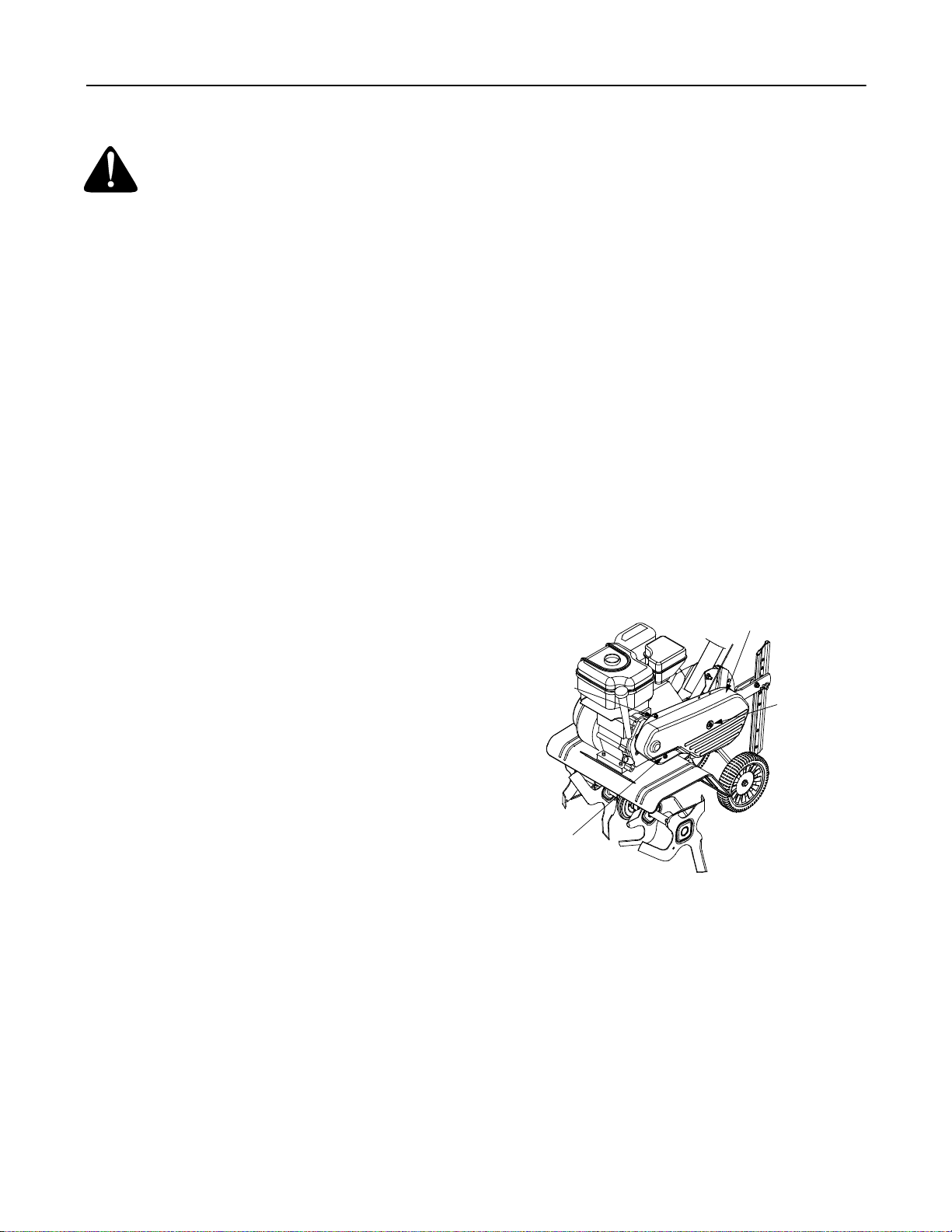
Belt Replacement
Your tiller has been engineered with a belt made of
special material (Kevlar Tensile) for longer life and
better performance. It should not be replaced with an
off-the-shelf belt. Order all belts through your
authorized service dealer.
• Disconnect and ground spark plug wire against the
engine.
• Remove the two hex washer screws from the front
of the belt cover and remove the lock nut and flat
washer from the side of the belt cover.
• Remove the belt cover. See Figure 11.
Belt Cover
Hex Washer
Screw
Lock Nut &
Flat Washer
Lubrication
Transmission
The transmission is pre-lubricated and sealed at the
factory. It requires no checking. See an authorized
service dealer for any service issues.
Clutch Handle
Lubricate the pivot point on the clutch handle and the
cable at l east once a seas on wi th li ght oi l. Th e cont rol
must operate freely in both directions.
Pivot Points
Lubricate all pivot points and linkages at least once a
season with light oil.
Tine Shafts
Remove tine assemblies and lubricate the tine shafts at
least once a season.
Wheel Shafts
Remove wheel assemblies and lubricate the axle shafts
at least once a season.
Hex Washer
Screw
Figure 11
• Remove the hex screw and idler pulley from the
idler bracket assembly. See Figure 12.
• Reassemble the new belt and reattach idler pulley
to secure in place.
• Replace belt cover assembly and secure with the
hardware removed earlier.
10
Page 11
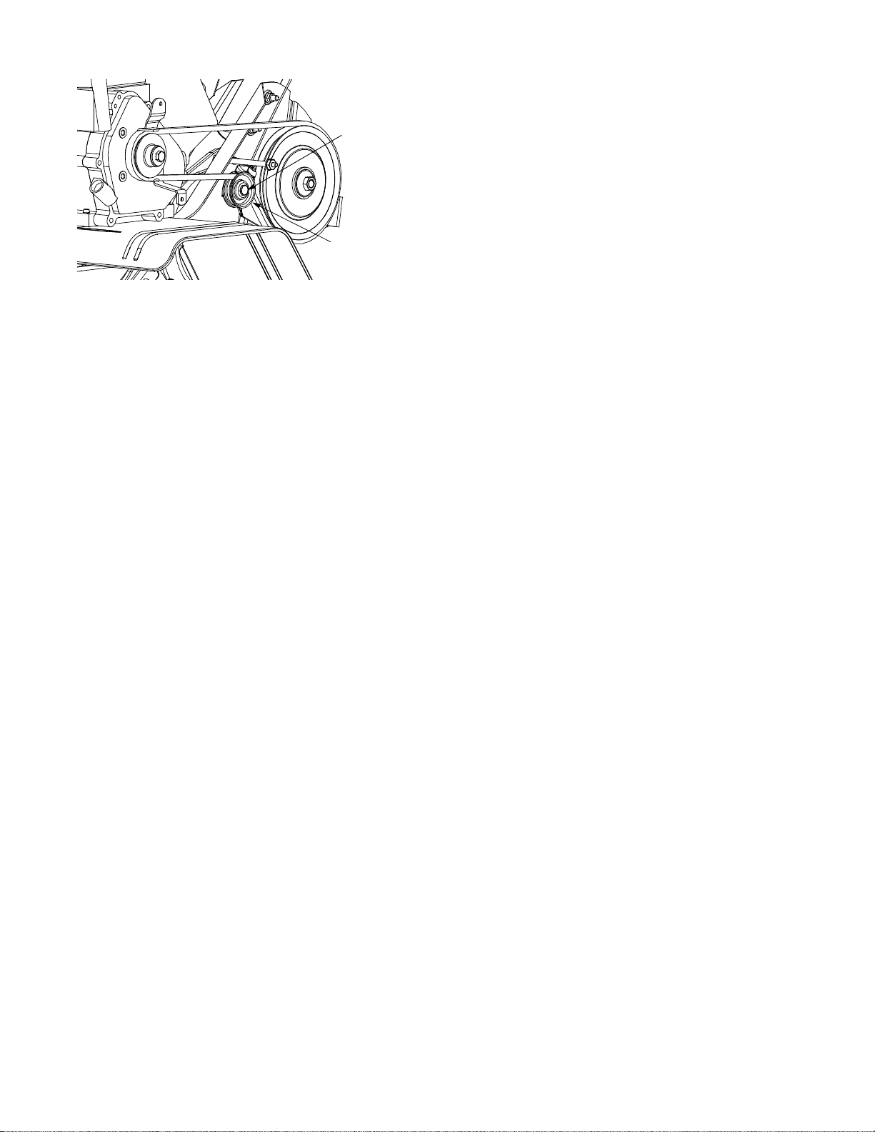
Hex Screw
Idler Pulley
• We do not recommend the use of pressure
washers to clean your unit. They may cause
damage to electric components, spindles, pulleys,
bearings or the engine. The use of pressure
washers will result in shortened life and reduce
serviceability.
• Refer to the engine manual for correct engine
storage instructions.
• Wipe tines with oiled rag to prevent rust.
• Store tiller in a clean, dry area. Do not store next to
corrosive materials, such as fertilizer.
Figure 12
Off-Season Storage
If the tiller will not be used for a period longer than 30
days, the following steps should be taken to prepare the
tiller for storage.
• Clean the exterior of engine and the entire tiller
thoroughly. Lubricate the tiller as described in the
lubrication instructions.
NOTE:
an unventilated or metal sto rage shed, care shou ld be
taken to rustproof the equipment. Using a light oil or
silicone, coat the equipment and especially any
springs, bearings, and cables.
When storing any type of po wer equipme nt in
11
Page 12

SECTION 7: TROUBLESHOOTING
Problem Cause Remedy
Engine fails to start 1. Spark plug wire disconnected.
2. Fuel tank empty or stale fuel.
3. Throttle control lever not in correct
starting position. (If equipped)
4. Choke no t in ON posit ion.
5. Blocked fuel line.
6. Faulty spark plug.
7. Engine flooded
Engine runs erratic 1. Spa rk plug wir e loose.
2. Unit running on CHOKE.
3. Blocked fuel line or stale fuel.
4. Vent plugged.
5. Water or dirt in fuel system.
6. Dirty air cleaner.
7. Carburetor out of adjustment.
Engine overheats 1. Engine oil level low.
2. Dirty air cleaner.
3. Air flow restricte d.
4. Carburetor not adjusted properly.
Tines do not engage 1. Foreign object lodged in tines.
2. Tine clevis pin(s) missing.
3. Control cable not adjusted properly.
4. Belt worn and/or stretched.
5. Pulley and idler not in correct
adjustment.
NOTE: For repairs beyond the minor adjustments listed above, contact your nearest service dealer.
1. Connect wire to spark plug.
2. Fill tank with clean, fresh gasoline.
3. Move throttle lever to start position.
4. Move lever to ON position.
5. Clean fuel line.
6. Clean, adjust gap, or replace.
7. Wait a few minutes to restart, but do not
prime. (If Equipped)
1. Connect and tighten spark plug wire.
2. Move choke lever to OFF position.
3. Clean fuel line; fill tank with clean, fresh
gasoline
4. Clear ve nt.
5. Drain fuel tank. Refill with fresh fuel.
6. Clean following engine manual.
7. Refer to engine manual.
1. Fill crankcase with proper oil.
2. Clean air cleaner.
3. Remove blower housing and clean.
4. Refer to engine manual.
1. Stop tiller completely, check and
discard foreign object.
2. Replace tine clevis pin(s).
3. Adjust control cable.
4. Replace belt.
5. Take unit to authorized service dealer.
12
Page 13

SECTION 8: NOTES
13
Page 14
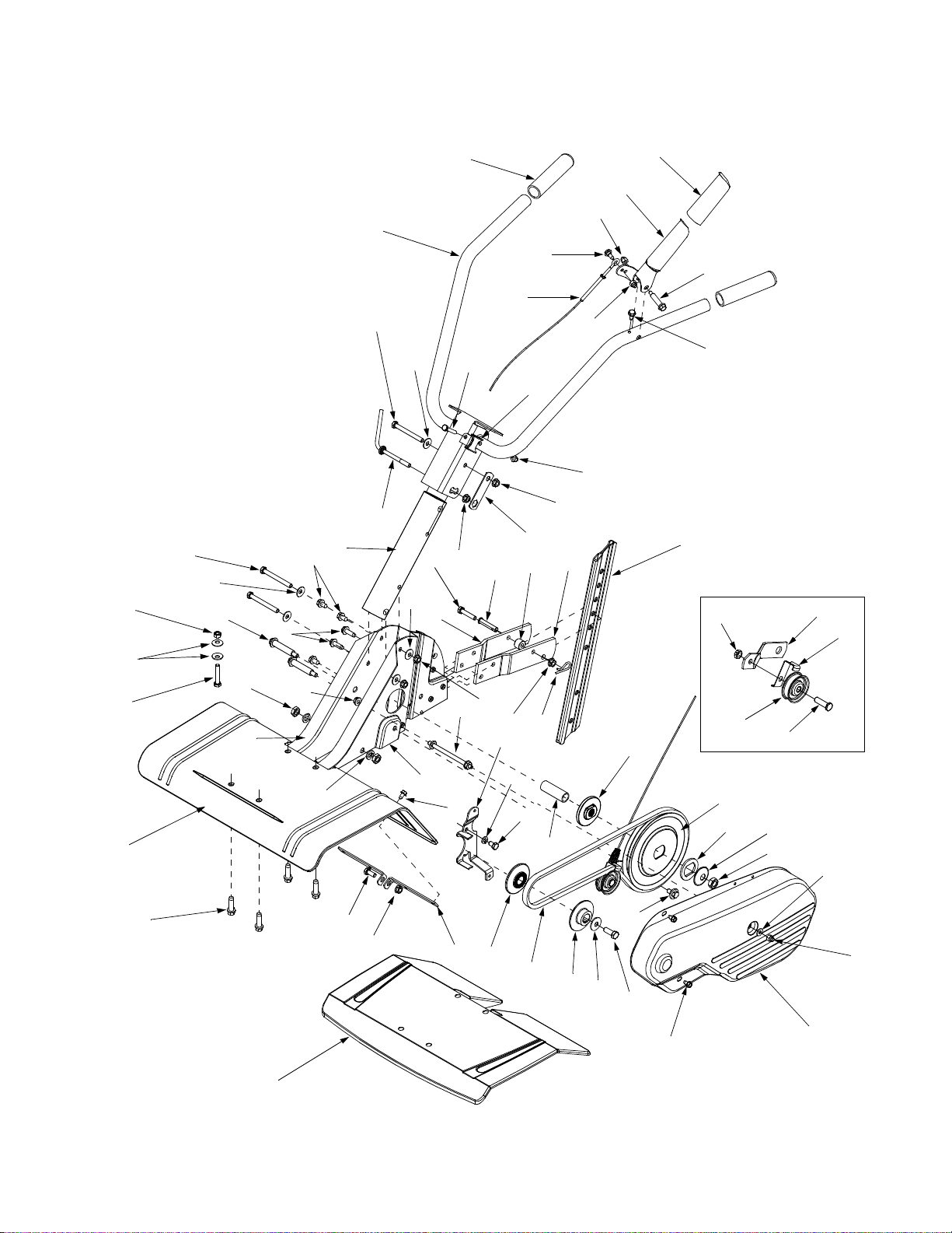
Model Series 300 & 330
25
10
26
1
4
6
7
9
10
11
9
10
29
28
30
32
16
27
10
34
17
21
14
35
12
14
18
42
24
13
15
19
23
5
5
5
14
20
2
3
8
6
22
61
64
46
62
63
65
37
38
41
31
39
34
33
36
40
14
47
43
44
49
45
48
50
60
51
56
52
53
54
55
59
58
57
Page 15

Model Series 300 & 330
Ref.
No.
1. 720-0274 Grip
2. 731-0473 Clutch Gri p
3. 686-0002 Clutch Lever
4. 649-0137 Handle Assembly
5. 712-0442 Lock Nut Cap 1/4-20
6. 738-1225 Shoulder Screw
7. 746-1148 Clutch Cable
8. 738-1226 Shoulder Screw
9. 710-0189 Hex Cap Screw 5/16-18 x 3 .0
10. 736-0242 Bell Washer .340 ID x .872 OD
11. 786-0340 Adjustable Handle Crank
12. 710-0606 Hex Cap Screw 1/4-20 x 1.5
13. 719-0279 Rope Guide
14. 712-0720 Flange Nut 5/16-18
15. 786-0341 Retainer Bracket
16. 649-0136 Handle Tube
17. 710-0805 Hex Cap Screw 5/16-18 x 1.5
18. 711-0415 Clevis Pin 3/8 x 1.62
19. 750-0890 Spacer
20. 786-0003 Tailpiece Bracket LH
21. 786-0004 T ailpiec e Bracket RH
22. 786-0005 Depth Bar
23. 714-0149B Cotter Pin
24. 712-3004A Hex Flange Locknut 5/16-18
25. 712-3010 Hex Nut 5/16-18
26. 710-3180 Hex Cap Screw 5/16-18 x 1.75
27. 710-0604A Hex Washer Screw 5/16-18 x .625
28. 710-0602 Hex Washer Screw 5/16-18 x 1.0
29. 738-0934 Shoulder Screw
30. 712-0240 Jam Nut 7/16-20
31. 736-0171 Lock Washer 7/16
32. 786-0138A Frame RH
33. 786-0139A Frame LH
Part No. Part Description
Ref.
No.
34. 712-3004A Flange Lock Nut 5/16-18
35. 711-0919 Belt Cover Belt
36. 710-0599 Hex Washer Screw 1/4-20 x .500
37. 786-0035A Tine Shield 20”
38. 710-0502A Hex Washer Screw 3/8-16 x 1.25
39. 710-3008 Hex Cap Screw 5/16-18
40. 786-0053 Tine Shield Bracket 20”
41. 786-0337 Tine Shield 18”
42. 786-0039B Cover Bracket
43. 736-0119 Lock Washer 5/16
44. 710-0107 Hex Cap Screw 5/16-24 x .50
45. 750-0892 Input Spacer .64 ID x 2.4 Lg
46. 748-0350 Pulley Adapter
47. 756-0971 Engine Inner Half Pulley
48. 756-0972 Engine Outer Half Pulley
49. 754-0428 Belt
50. 736-0452 Bell Washer .396 ID x 1.140 OD
51. 710-0152 Hex Cap Screw 3/8-24 x 1.0
52. 756-0585 Flat Pulley
53. 736-0312 Retainer Bearing Washer
54. 736-0112 Spherical Washer .531 ID x .620 OD
55. 712-3029 Jam Nut 1/2-20
56. 710-0599 Hex Washer Screw 1/4-20 x .50
57. 786-0056 Cover Belt
58. 712-0392 Lock Nut Cap 1/4-28
59. 736- 3020 Flat Washer .271 ID x .630 OD
60. 738-0930 Shoulder Screw
61. 712-0266 Jam Nut 3/8-16
62. 786-0144 Idler Bracket
63. 786-0149 Idler Keeper Bracket
64. 756-0313 Flat Idler
65. 710-0723 Hex Cap Screw 3/8-16 x 1.25
Part No. Part Description
15
Page 16
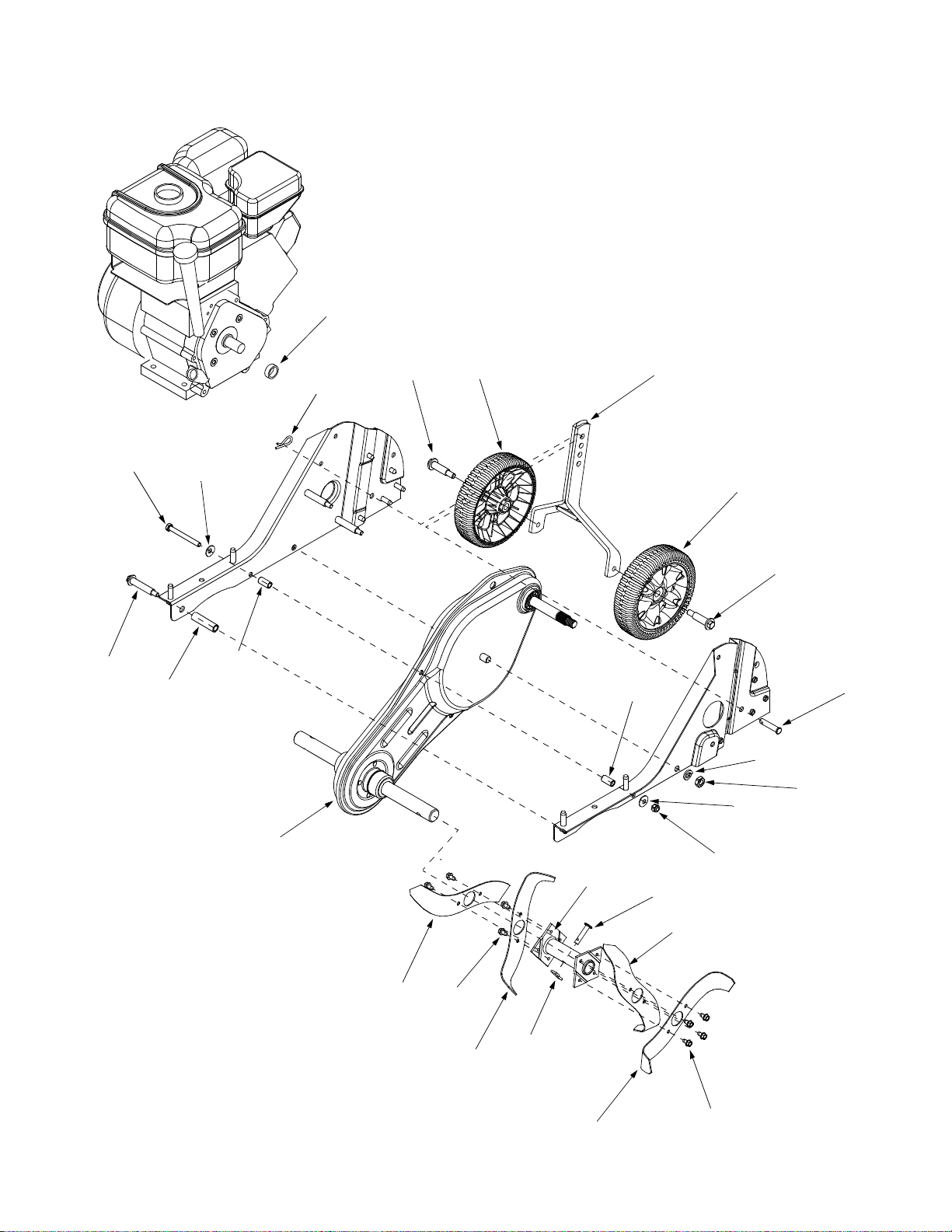
Model Series 300
19
10
3
1
2
5
13
14
6
2
4
7
8
6
10
9
1
11
15
18
16
16
12
20
4
16
17
15
18
Page 17

Model Series 300
Ref.
No.
1. 734-1988 Wheel 7 x 1.8
2. 738-0929 Shoulder Screw
3. 686-0081A Wheel Bracket Assembly
4. 714-0149B Cotter Pin
5. 711-0415 Clevis Pin
6. 736-0242 Bell Washer .340 ID x .872 OD
7. 710-0189 Hex Cap Screw 5/16-18 x 3.0
8. 738-0934 Shoulder Screw
9. 750-0273 Spacer .51 ID x . 69 OD x 1.97Lg
10. 750-0470 Spacer .47 OD x .96Lg
Part No. Part Description
Ref.
No.
11. 686-0189 Chain Case Assembly
12. 712-0429 Hex Lock Nut 5/16-18
13. 736-0171 Lock Washer 7/16
14. 712-0240 Jam Nut 7/16-20
15. 04922 Tine Blade 9.5” RH
16. 04923 Tine Blade 9.5” LH
17. 711-0702 Clevis Pin
18. 710-0599 Hex Washer Screw 1/4-20 x .50
19. 750-0456 Spacer .790 ID x .347 Lg
20 04918 Tine Adapter Assembly
Part No. Part Description
17
Page 18
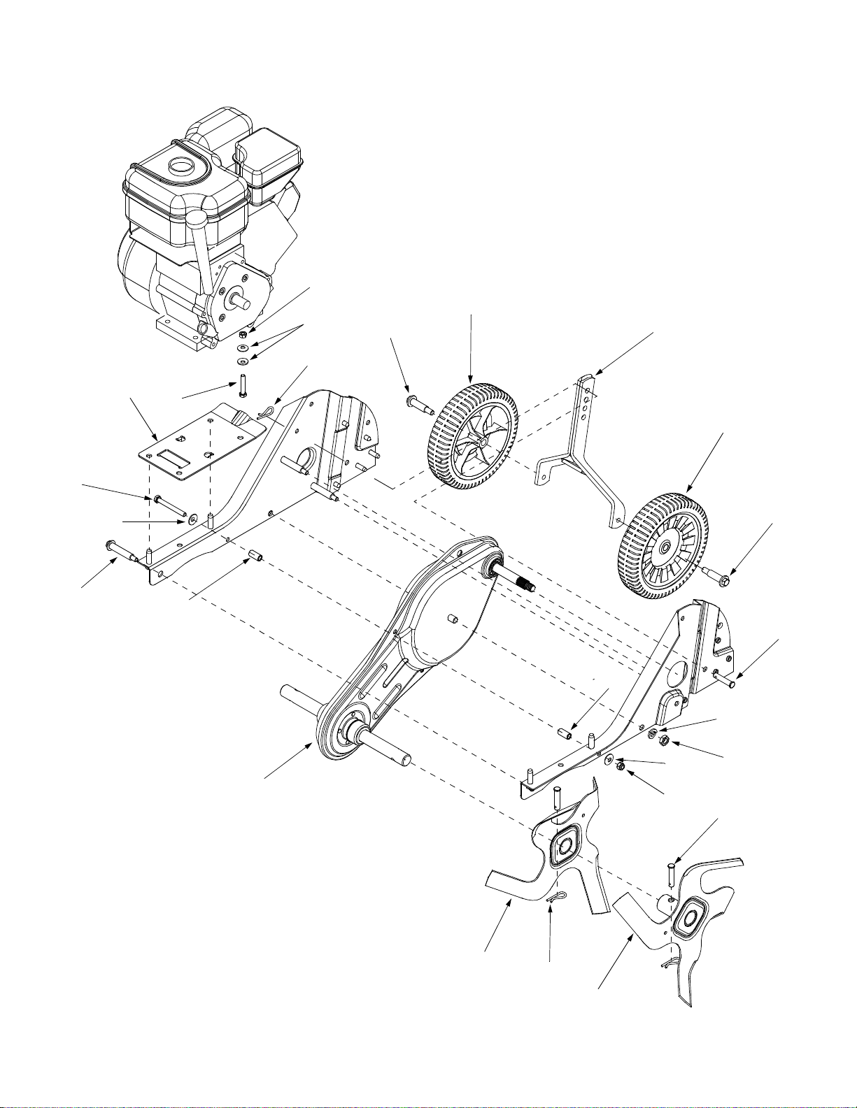
Model Series 330
4
18
17
1
2
3
9
7
6
8
19
10
11
10
6
12
1
2
5
13
14
5
18
15
4
16
Page 19

Model Series 330
Ref.
No.
1. 734-1781 Wheel 8 x 1.75
2. 738-0929 Shoulder Screw
3. 686-0081A Wheel Bracket Assembly
4. 714-0149B Cotter Pin
5. 711-0415 Clevis Pin
6. 736-0242 Bell Washer .340 ID x .872 OD
7. 710-0189 Hex Cap Screw 5/16-18 x 3.0
8. 738-0934 Shoulder Screw
9. 786-0145A Engine Mounting Plate
10. 750-0470 Spacer .47 OD x .96Lg
11. 686-0091 Chain Case Assembly
Part No. Part Description
Ref.
No.
12. 712-0429 Hex Lock Nut 5/16-18
13. 736-0171 Lock Washer 7/16
14. 712-0240 Jam Nut 7/16-20
15. 642-0002 Inner Tine Assembly - RH 12”
16. 642-0004 Outer Tine Assembly -RH 12”
17. 712-3010 Hex Nut 5/16-18
18. 736-0242 Bell Washer .340 ID x .872 OD
19. 710-3180 Hex Cap Screw 5/16-18 x 1.75
Part No. Part Description
642-0003 Inner Tine Assembly - LH 12”
642-0005 Outer Tine Assembly - LH 12”
19
Page 20

MANUFACTURE R’S LIMITED WARRANTY FOR:
The limited warranty set forth below is given by MTD LLC
with respect to new merchandise purchased and used in the
United States, its possessions and territories.
MTD LLC warrants this product against defects for a period
of two (2) years commen cing on the date of original p urchase
and will, at its option, repair or replace, free of charge, any
part found to be defective in materials or workmanship. This
limited warranty shall only apply if this product has been
operated and maintain ed in accordance with the Operator’s
Manual furnished with the product, and has not been subject
to misuse, abuse, commercial use, neglect, accident,
improper maintenance, alteration, vandalism, theft, fire,
water, or damage because of other peril or natural disaster.
Damage resulting from the installation or use of any accessory or attachment not approved by MTD LLC for use with
the product(s) cov ere d b y this manual will vo id your warranty
as to any resulting damage.
Normal wear parts or components thereof are subject to separate terms as follows: All normal wear pa rts or component
failures will be covere d on th e produc t for a p eriod o f 90 day s
regardless of cause. After 90 days, but within the two year
period, normal wear part failures will be covered ONLY IF
caused by defects in materials or workmanship of OTHER
component parts. Normal w ear p arts and components
include, but are not limited to: batteries, belts, blades, blade
adapters, grass bags , rider deck wheels, se ats, snow thrower
skid shoes, shave plates, auger spiral rubber, tires.
HOW TO OBTAIN SERVICE: Warranty service is available,
WITH PROOF OF PURCHASE, through your local authorized service dealer. To loca te the deal er in your are a, chec k
your Yellow Pages, or contact MTD LLC at P.O. Box 361131,
Cleveland, Ohio 44136-0019, 1-800-800-7310, 1-330-2204683 or log on to our Web site at www.mtdproducts.com.
This limited warranty doe s not provi de cove rage in the fo llowing cases:
a. The engine or component parts thereof. These items
carry a separate manufacturer’s warranty. Refer to the
applicable manufacturer’s warranty for terms and conditions.
b. Log spli tter pumps, valves, and cylinders have a sepa-
rate one year warranty.
c. Routine maintenance items such as lubricants, filters,
blade sharpening, tune-ups, brake adjustments, clutch
adjustments, deck adjustments, and normal de terioration
of the exterior finish due to use or exposure.
d. MTD LLC does not extend any warranty for products
sold or exported outside of the United States, its possessions and territories, except those sold through MTD
LLC’s authorized c han nel s of exp ort dis trib utio n.
e. Parts that are not ge nuine MTD par ts a re n ot covere d by
this warranty.
f. Service completed by so meone other tha n an authorized
service dealer is not covered by thi s warrant y.
g. Transportation charges and service calls are not
covered.
No implied warranty, including any implied warranty of
merchantability of fitness for a particular purpose,
applies after the applicable period of express written
warranty above as to the parts as identified. No other
express warranty, whether written or oral, except as
mentioned above, given by any person or entity, including a dealer or retailer, with respect to any product, shall
bind MTD LLC. During the period of the warranty, the
exclusive reme dy is repair or replaceme nt of the pr oduct
as set forth above.
The provisions as set forth in this warranty provide the
sole and exclusive remedy arising from the sale. MTD
LLC shall not be liable fo r incidental or consequential
loss or damage including, without limitation, expenses
incurred for substitute or replacement lawn care services or for rent al expenses to temporarily replace a warranted product.
Some states do not allow the exclusion or limitation of incidental or consequential damages, or limitations on how long
an implied warranty lasts, so the above exclusions or limitations may not apply to you.
In no event shall recovery of any kind be greater than the
amount of the purchase p rice of the produc t sold. Alteration
of safety features of th e produc t shall v oid this warra nty.
Y ou assu me the risk a nd liabi lity for loss , damage, or injury to
you and your property and/or to others and their property
arising out of the misuse or inability to use the product.
This limited warranty shall not extend to anyone other than
the original purchaser or to the person for whom it was purchased as a gift.
HOW STATE LAW RELATES TO THIS WARRANTY: This
limited warranty gives you specific legal rights, and you
may also have other rights which vary from state to
state.
MTD LLC, P.O. BOX 361131 CLEVELAND, OHIO 44136-0019 1-800- 800-7310
 Loading...