

Page 1
Owner’s Manual
CRAFTSMAN
6.5 Horse Power
Self-Propelled
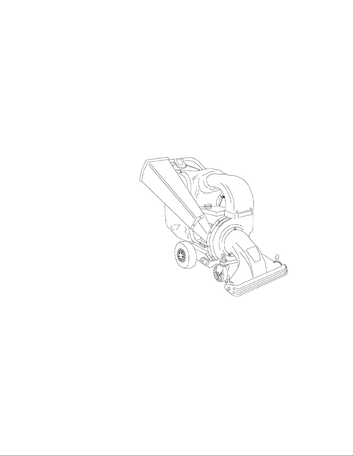
CHIPPER-SHREDDER VACUUM
Model No.
247.77763
CAUTION: Before using this product,
read this manual and follow all Safety
Rules and Operating Instructions.
Sears, Roebuck and Co., Hoffman Estates, IL 60179, U.S.A.
Printed in U.S.A.
770-10034
(8/98)
Page 2
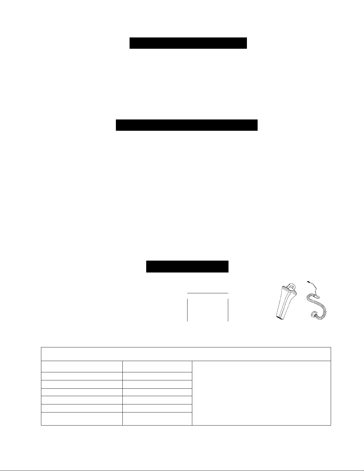
TABLE OF CONTENTS
Content Page
Warranty Information 2 Service & Adjustment
Safe Operation Practices
Assembly 5
Operation 8 Parts List
Maintenance
3
13
Content
Off-Season Storage
Trouble-Shooting
WARRANTY INFORMATION
One-Year Warranty on Craftsman Chipper-Shredder Vacuum
For one year from the date of purchase, when this Craftsman chipper-shredder vacuum is maintained, lubricated,
and tuned up according to the operating and maintenance instructions in the owner’s manual, Sears will repair,
free of charge, any defect in material or workmanship.
This warranty excludes blades, chipper blades, flails, air cleaners, spark plugs, catcher bags and tires which are
expendable parts and become worn during normal use.
If this chipper-shredder vacuum is used for commercial or rental purposes, this warranty applies for only 30 days
from the date of purchase.
WARRANTY SERVICE IS AVAILABLE BY CONTACTING THE NEAREST SEARS SERVICE CENTER IN THE
UNITED STATES. THIS WARRANTY APPLIES ONLY WHILE THIS PRODUCT IS IN USE IN THE UNITED
STATES.
Page
15
17
18
19
This warranty gives you specific legal rights, and you may also have other rights which vary from state to state.
Sears, Roebuck and Co., D/817WA, Hoffman Estates, II 60179
ACCESSORIES
These accessories are
available where the unit was
purchased. They are also
available at most Sears retail
outlets, and service centers.
Most Sears stores can order
repair parts for you when you
provide the model number of
your Craftsman chippershredder vacuum.
Horsepower:
Engine Oil Type
Engine Oil Capacity
Fuel Capacity:
Spark Plug
Spark Plug Gap
Tire Pressure
'Till
jy
Air
Filter
Plug
PRODUCT SPECIFICATION
6.5 Horse Power
SAE30
20 Ounces
Approx. 3 Quarts
Champion RN4C
.030"
24 P.S.I.
Engine Gas Fuel
Oil
HEEy
\ Gasoline
J
Can
Model Number
Serial Number.................................................................
Date of Purchase
Record both serial number and date of purchase and
keep in a safe place for future reference.
A
i
\r\
y
Stabilizer
.........
247;77763......................................
............................................................
10-foot
Hose Kit
Page 3

dk
A
SAFE OPERATION PRACTICES
This symbol points out important safety instructions which, if not followed, could endanger the per
sonal safety and/or property of yourself and others. Read and follow all instructions in this manual before
attempting to operate your chipper-shredder vacuum. Failure to comply with these instructions may result in
personal injury. When you see this symbol—heed its warning.
Your chipper-shredder vacuum was built to be operated according to the rules for safe opera-
DANGER" manual. As with any type of power equipment, carelessness or error on the part of
■ the operator can result in serious injury. If you violate any of these rules, you may cause seri
ous injury to yourself or others.
This unit is equipped with an internal combustion engine and should not be used on or near any unimproved
forest-covered, brush-covered or grass-covered land unless the engine’s exhaust system is equipped with a
spark arrester meeting applicable local or state laws (if any). If a spark arrester is used, it should be
maintained in effective working order by the operator.
In the State of California the above is required by law (Section 4442 of the California Public Resources
Code). Other states may have similar laws. Federal laws apply on federal lands. A spark arrester for the
muffler is available through your nearest Sears Authorized Service Center (See the REPAIR PARTS section
of this manual.)
General Operation
• Read this owner’s guide carefully in its entirety before
attempting to assemble this machine. Read,
understand, and follow all instructions on the machine
and in the manual(s) before operation. Be completely
familiar with the controls and the proper use of the
machine before operating it. Keep this manual in a
safe place for future and regular reference and for
ordering replacement parts.
• Your chipper-shredder vacuum is a powerful tool, not a
plaything. Therefore, exercise extreme caution at all
times. Your unit has been designed to perform two
jobs; to chip and vacuum vegetation found in a normal
yard. Do not use it for any other purpose.
• Never allow children under 16 to operate the unit.
Children 16 years and older should only operate under
close parental supervision. Only responsible
individuals who are familiar with these rules of safe
operation should be allowed to use your unit.
• Keep the area of operation clear of all persons,
particularly small children and pets. Stop the engine
when they are in the vicinity of the unit.
• When feeding material into this equipment, be
extremely careful that pieces of metal, rocks, bottles,
cans or other foreign objects are not included.
Personal injury or damage to the machine could result.
• Always wear safety glasses or safety goggles, during
operation and while performing an adjustment or
repair, to protect eyes from foreign objects that may be
thrown from the machine.
• Wear sturdy, rough-soled work shoes and close fitting
slacks and shirt. Shirt and slacks that cover the arms
and legs and steel-toed shoes are recommended. Do
not wear loose fitting clothes or jewelry, and secure
hair above shoulder length. They can be caught in
moving parts. Never operate a unit in bare feet,
sandals or sneakers. Wear gloves when feeding
material in the chipper chute.
Do not operate the unit while under the influence of
alcohol or drugs.
Do not over-reach. Keep proper footing and balance at
all times.
Never place your hands or any part of your body or
clothing near or under rotating parts. Keep clear of the
discharge opening at all times Never insert your
hands or any part of your body or clothing into the
nozzle, chipper chute or discharge opening as the
rotating impeller can cause serious injury.
If it is necessary for any reason to unclog the feed
intake or discharge openings or to inspect or repair any
part of the machine where a moving part can come in
contact with your body or clothing, stop the machine,
allow it to cool, disconnect the spark plug wire from the
spark plug and move it away from the spark plug
before attempting to unclog, inspect or repair.
Never operate unit without vacuum bag and discharge
chute properly affixed to unit. Large zippered end of
bag must be closed to prevent objects from being
blown out.
Never operate unit without either the inlet nozzle or
optional hose attachment properly affixed to unit.
These devices shield the operator from accidental
contact with the rotating impeller. Never attempt to
convert the unit from nozzle to hose mode or vice versa
with the engine running.
Never attempt to remove or empty vacuum bag when
engine is running. Shut the engine off and wait for the
impeller to come to a complete stop before removing
the bag. The impeller continues to rotate for a few
Page 4

• seconds after the engine is shut off. Never place any
part of the body in the impeller area until you are sure
the impeller has stopped rotating.
• Keep all guards and safety devices in place and
operating properly.
• Do not allow an accumulation of processed material
to build up in the discharge area as this will prevent
proper discharge and can result in kick-back from the
chipper chute.
• Keep your face and body back from chipper chute to
avoid accidental bounce back of any material.
• If the cutting mechanism strikes a foreign object or if
your machine should start making an unusual noise
or vibration, immediately stop the engine, disconnect
the spark plug wire and move the wire away from the
spark plug. Allow the machine to stop and take the
following steps:
a. Inspect for damage
b. Repair or replace any damaged parts.
c. Check for any loose parts and tighten to assure
continued safe operation.
• Muffler and engine become hot and can cause a burn.
Do not touch.
• Do not allow leaves or other debris to build up on
engine’s muffler. The debris could ignite and cause a
fire.
• Do not operate engine if air cleaner or cover over
carburetor air-intake is removed, except for
adjustment. Removal of such parts could create a fire
hazard.
Children
Tragic accidents can occur if the operator is not alert to the
presence of small children. Children are often attracted to
the chipping and vacuuming activity. Never assume that
children will remain where you iast saw them.
• Keep children out of the work area and under the
watchful eye of a responsible adult other than the
operator.
• Be alert and turn the unit off if a child enters the area.
• Never allow children under the age of 16 to operate
the chipper-shredder vacuum.
• Check and add fuel before starting the engine. Never
remove gas cap or add fuel while the engine is
running. Allow engine to cool at least two minutes
before refueling.
• Replace gasoline cap securely and wipe off any
spilled gasoline before starting the engine as it may
cause a fire or expiosion.
• Extinguish all cigarettes, cigars, pipes and other
sources of ignition.
• Never refuel unit indoors because flammable vapors
will accumulate in the area.
• Never store the machine or fuel container inside
where there is an open flame or spark such as a gas
hot water heater, clothes dryer or furnace.
• Never run your machine in an enclosed area as the
exhaust from the engine contains carbon monoxide,
which is a odorless, tasteless and deadly poisonous
gas.
• To reduce fire hazard, keep engine and muffler free of
leaves, grass, and other debris build-up. Clean up
fuel and oil spillage. Allow unit to cool at least 5
minutes before storing.
• Before cleaning, repairing, or inspecting, make certain
the impeller and all moving parts have stopped.
Disconnect the spark plug wire and keep wire away
from spark plug to prevent accidental starting. Do not
use flammable solutions to clean air filter.
• Keep all nuts, bolts, and screws tight to be sure the
equipment is in safe working condition.
• Nevertamper with safety devices. Check their proper
operation regularly.
• After striking a foreign object, immediately stop the
engine, disconnect the spark plug wire from the spark
plug, and thoroughly inspect the unit for any damage.
Repair damage before starting and operating unit.
• Do not alter or tamper with the engine’s governor
setting. The governor controls the maximum safe
operating speed of the engine. Over-speeding the
engine is dangerous and will cause damage to the
engine and to other moving parts of the machine.
• Checkthe vacuum bag frequently for wear. Replace if
worn or damaged.
• Keep vacuum bag free of debris when not in use.
Service
• Use extreme care in handling gasoline and other
fuels. They are extremely flammable and the vapors
are explosive.
• Store fuel and oil in approved containers, away from
heat and open flame, and out of the reach of children.
SAVE THESE INSTRUCTIONS FOR FUTURE REFERENCE.
Your Responsibility
Restrict the use of this power machine to
persons who read, understand and follow the
A
warnings and instructions in this manual and on
the machine.
Page 5
ASSEMBLY
IMPORTANT: This unit is shipped without gasoline
or oil in the engine. After assembly, see
OPERATION section of this manual for proper fuel
and engine oil fill-up.
NOTE: To determine right and left hand sides of your
chipper-shredder vacuum, stand behind the unit with
the engine farthest away from you.
Your chipper-shredder vacuum has been completely
assembled at the factory, except for the nozzle, the
chipper chute with support bracket and the catcher bag.
These parts are shipped loose in the carton. A pair of
safety glasses and a 20-oz. bottle of engine oil are also
included in the carton.
Removing From Carton
• Cut the corners of the carton.
• Remove all packing inserts.
• Remove ail loose parts. See Figure 1.
• Push down on handle to lift front of chippershredder vacuum and roll unit out of the carton.
• Make certain all parts and literature have been
removed before the carton is discarded.
r-j
20-oz. Bottle
of Engine Oil
Figure 1
with Support Bracket
Loose Parts
(See Figure 1.)
1. Nozzle
2. Chipper Chute with Support Bracket
3. Catcher Bag
4. Safety Glasses (Not Shown in Figure 1 )
5. A 20-oz. Bottle of Engine Oil
Tools Required
1. 1 /2" or adjustable wrenches
2. 7/16” or adjustable wrenches
3. Funnel (Recommended)
4. Pliers
Disconnecting Spark Plug
(See Figure 2.)
• Before proceeding with assembly of your new
chipper-shredder vacuum unit, disconnect the
spark plug wire from the spark plug on the
engine and move it away. This will prevent
accidental starting of the engine in any way.
Page 6
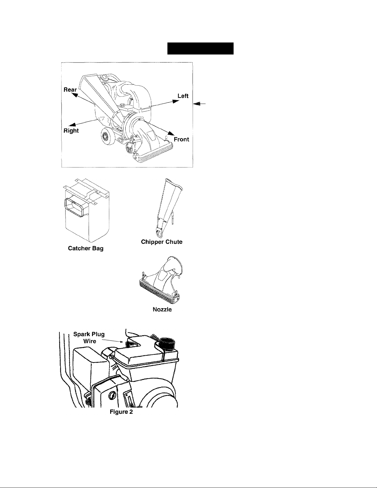
Attaching the Nozzle
(See Figure 3.)
• Remove the three plastic wing nuts from the
front of the chipper-shredder vacuum.
• Place the nozzle over the three weld studs.
• Secure with the plastic wing nuts just removed.
Plastic
Wing Nuts
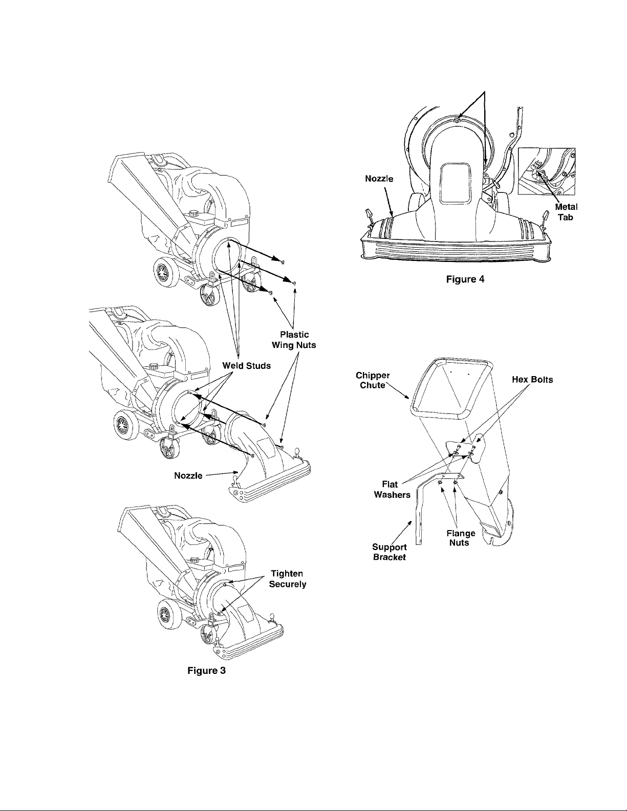
Attaching the Chipper Chute
• Loosen, but do NOT remove, the two hex bolts,
flat washers, and flange nuts which are secured
to the support bracket. See Figure 5.
NOTE: The metal tab in the nozzle must depress the
safety switch on the front of the chipper-shredder
vacuum or the engine will not start. See Figure 4.
Figure 5
Remove the two flange nuts, hex bolts and
saddle washers which secure the right side of
the upper handle to the right side of the lower
handle. See Figure 6.
Next, remove the three hex nuts and bell
washers from the weld studs found beside the
opening on the right side of the chipper-shredder
vacuum. See Figure 6.
Page 7
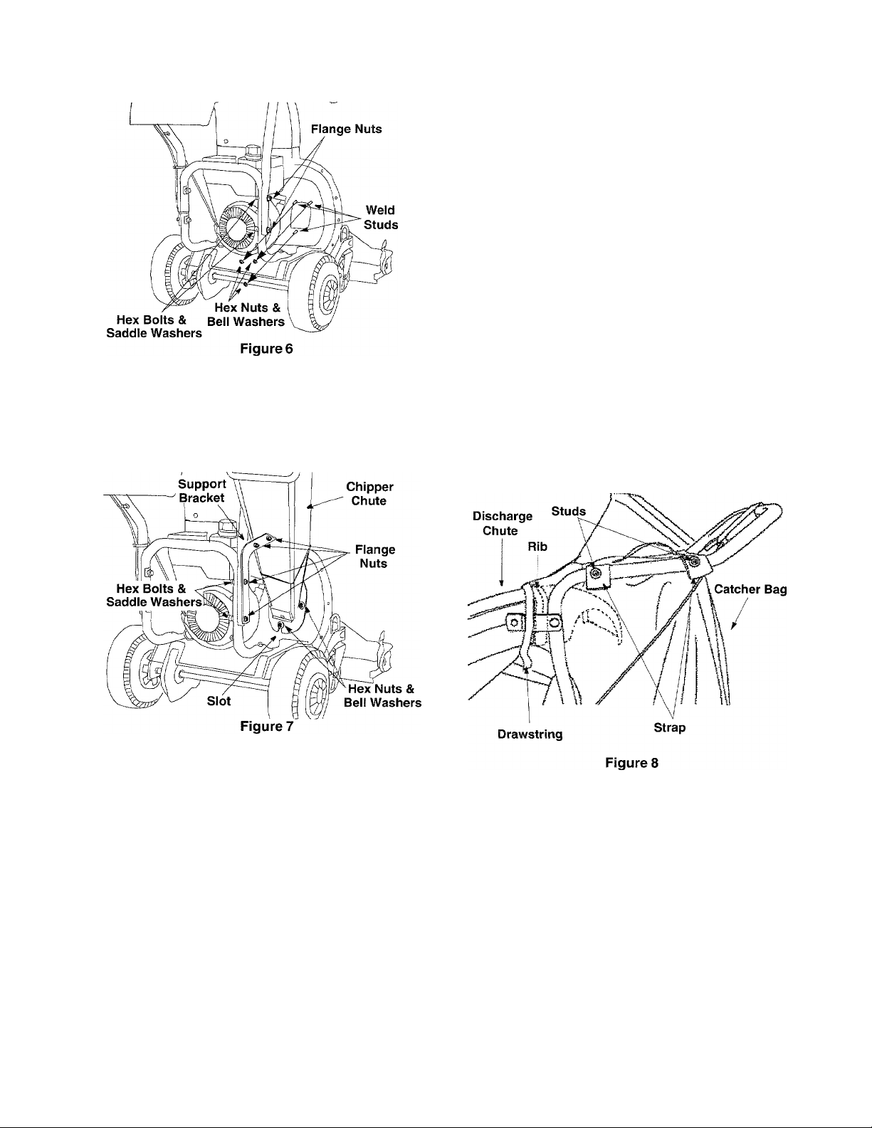
Place the chipper chute over the weld studs
keeping the slotted side towards the bottom.
Loosely secure with the three hex nuts and bell
washers that were removed earlier. Do not fully
tighten the hex nuts at this point in the assembly.
See Figure 7.
• Align the support bracket with the holes in the
right side of the upper and lower handles where
the hex bolts were just removed. Push up
slightly on the chipper chute in order to better
align the holes in the support bracket with the
holes in the handles.
• Replace the hex bolts, saddle washers and
flange nuts to affix the support bracket to the
handle assemblies. See Figure 7.
• Follow by tightening all hardware securely first
on the chipper chute, then on the support
bracket, and finally on the handle.
Attaching the Catcher Bag
• Place the catcher bag inside of handle
assembly. Slip the opening on the bag over the
discharge chute, making certain it is over the rib
on the discharge chute.
• Place the four straps on the top of the bag over
the upper handle, hooking them on the studs.
• Squeeze the clamp on the drawstring and pull
the drawstring tight. Release the clamp. See
Figure 8.
Page 8
OPERATION
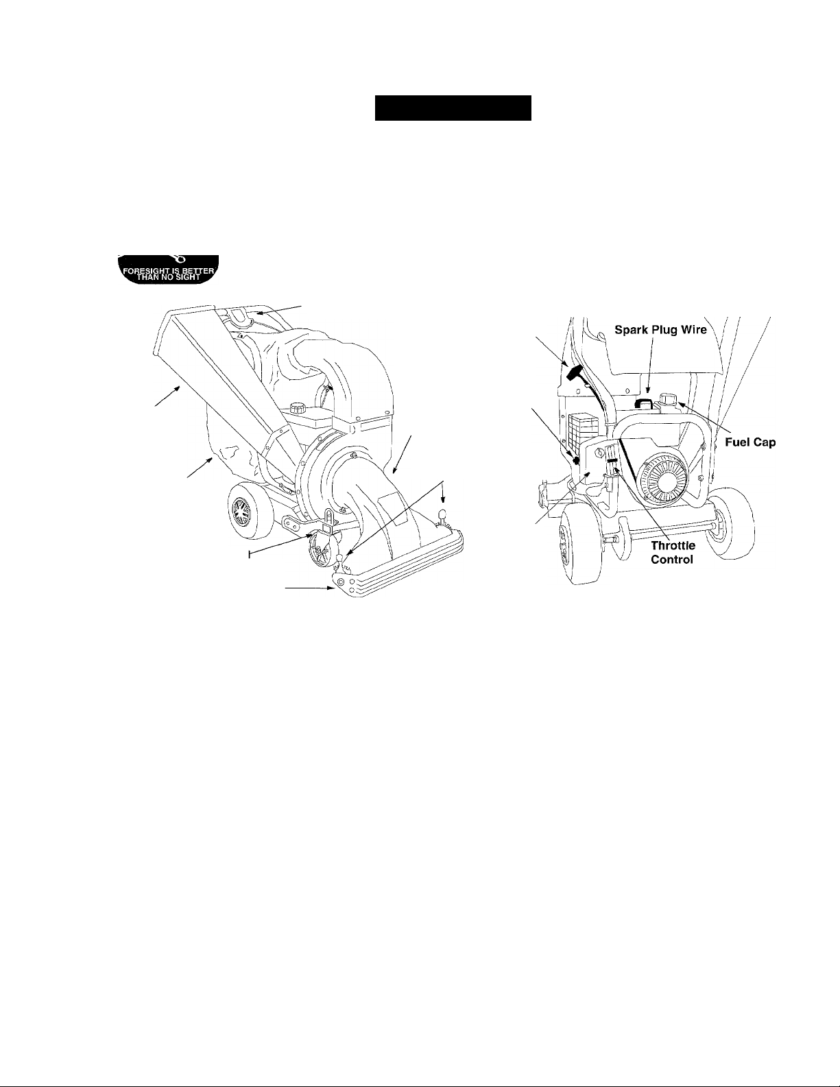
Know Your Chipper-Shredder Vacuum
Read this owner’s manual and safety rules before operating your chipper-shredder vacuum. Compare the
illustrations below with your equipment to familiarize yourself with the location of various controls and
adjustments. Save this manual for future reference.
11111 |ii| Wh The operation of any chipper-shredder vacuum can result in foreign objects being thrown into
^sAFET^AssEs'^ {|-|g eyes, which can result in severe eye damage. Always wear safety glasses, provided with
the Craftsman chipper-shredder vacuum, for operating this equipment or while performing any
adjustments or repairs on it.
Drive Clutch Control
Chipper
Chute
Catcher Bag
Front Caster Whee
Nozzle Door
Operating Controls
Chipper Chute
Allows twigs and small branches up to three inches in
diameter to be fed into the impeller for shredding.
Nozzle
Yard waste such as leaves and pine needles can be
vacuumed up through the nozzle.
Catcher Bag
Collects shredded material fed in through the chipper
chute or vacuumed in through the nozzle.
Drive Clutch Control
Squeezing the drive clutch control causes the
chipper-shredder vacuum to self-propel.
Nozzle Door
Nozzle ground clearance can be adjusted with the
nozzle door.
Starter
Handle
Primer
Nozzle
Nozzle Door Height
Adjustment Levers,
Air Filter
View from rear of
chipper-shredder vacuum
Figure 9
Front Caster Wheels
Allows for a choice in the manueverability of the
chipper-shredder vacuum.
Primer
The primer is used to assist in starting a cold engine
or restarting of a engine after a short shutdown.
Starter Handle
This is used to start the engine.
Throttle Control
Controls the engine speed and stops the engine.
Stopping the Engine
• Move throttle control lever to STOP position.
• Disconnect spark plug wire and move away from
the spark plug to prevent accidental starting while
the equipment is unattended.
Meets ANSi safety standards
Craftsman chipper-shredder vacuums conform to the safety standard of the American National Standards Institute (ANt
Page 9

Gas And Oil Fill-up
Oil (one 20-oz. bottle shipped with unit)
Only use high quality detergent oil rated with API
service classification SF, SG or SH. Select the oil’s
viscosity grade according to the expected operating
temperature. Follow the chart below.
NOTE: Although multi-viscosity oils (5W30, 10W30,
etc.) improve starting in cold weather, these
multiviscosity oils will result in increased oil
consumption when used above 32"F. Check engine
oil level more frequently to avoid possible engine
damage from running low on oil.
Colder
32°F
Warmer
A
A
A
WARNING: Never fill the fuel tank indoors.
Gasoline produces noxious fumes. Always
be certain to fill the fuel tank in a well
ventilated area to avoid inhalation of
gasoline fumes.
WARNING: Never smoke while fueling
your chipper-shredder vacuum. Gasoline
produces cumbustable fumes which can
ignite and cause personal injury.
WARNING: Do not fill closer than 1/2 inch
from the top of the fuel tank to prevent
spills and to allow for fuel expansion. If
gasoline is accidently spilled, move
chipper-shredder vacuum away from area
of spill. Avoid creating any source of
ignition until gasoline vapors have
disappeared.
5W30
Oil Viscosity Chart
• Remove oil fill dipstick.
• With the chipper-shredder vacuum on level
ground, use a funnel to fill engine with oil to
FULL mark on dipstick. Capacity is
approximately 20 oz. Be careful not to overfill.
Overfilling will cause the engine to smoke
profusely and will result in poor engine
performance. The oil bottle packaged with your
chipper-shredder vacuum contains 20 oz. of oil.
• Tilt chipper-shredder vacuum toward the left,
then re-level. Check the oil level making certain
not to rub the dipstick along the inside walls of
the oil fill tube. This would result in a false
dipstick reading. Refill to FULL mark on dipstick,
if necessary. Replace dipstick and tighten.
• Check oil level three times prior to starting
engine to be certain you’ve gotten an accurate
dipstick reading. Running the engine with too
little oil can result in permanent engine damage.
Gasoline
• Remove fuel cap from the fuel tank.
• Make sure the container from which you will
pour the gasoline is clean and free from rust or
foreign particles. Never use gasoline that may
be stale from long periods of storage in its
container. Gasoline that has been sitting for any
period longer than four weeks should be
considered stale.
• Fill fuel tank with approximately 3 quarts of
clean, fresh, lead-free grade automotive
gasoline. DO NOT use Ethyl or high octane
gasoline. Replace fuel cap.
SAE 30
• Check the fuel level periodically to avoid running
out of gasoline while operating the chippershredder vacuum. If the unit runs out of gas as it
is chipping, it may be necessary to unclog the
unit before it can be restarted. Refer to
Removing the Flail Screen
on page 15.
Starting The Engine
IMPORTANT: If your unit shows any sign of motion
with the drive clutch control in the disengaged
position, shut the engine off immediately. Readjust
following the instructions on page 16.
WARNING: Make sure that no one other
than the operator is standing near the
dk
A
chipper-shredder vacuum unit while starting
or operating.
Do not operate this unit unless the nozzle,
discharge chute, and the bag have been
properly installed.
Attach spark plug wire and rubber boot to spark
plug if not already attached.
Place the throttle control lever in FAST position.
Depress the primer three to four times slowly.
Wait about two seconds between each push.
When temperature is at or below 50°F/10°C, it
may be necessary to depress the primer five to
six times. You may have to use the primer to
restart a warm engine after a short shutdown.
Place one foot on the left rear wheel to prevent
the unit from skidding while starting.
Grasp starter handle and pull rope out slowly
until engine reaches start of compression cycle.
The rope will pull slightly harder at this point. Let
the rope rewind slowly.
Page 10
NOTE: While the engine is reaching the compression
cycle, you may hear a "clanking" noise. This noise is
caused by the impelier ftails pivoting and falling into
piace and iS normai. This noise wiii continue untili the
impeiier reaches full speed.
• Pull the rope with a rapid, continuous, full arm
stroke while keeping a firm grip on the starter
handle.
• Continuing to keep a firm grip on the starter
handle, let the rope rewind slowly. Do not let the
starter handle snap back against the eye bolt on
the handle. Repeat, if necessary, until engine
starts. Additional priming may be necessary.
• Move throttle control to IDLE position for a few
minutes to warm up the engine. Move it back to
fast when running.
• ALWAYS keep the throttle control in the Fast
postion when operating the chipper-shredder
vacuum.
NOTE: Engine may run very slowly for the first five to
ten seconds after it has been started untii the impeller
gains momentum and allows the engine to reach its
top RPM.
NOTE: To idie smoothly, a new engine may require 3
to 5 minutes of running at above the slow idle speed.
The idle speed has been adjusted for proper running
after this break-in period.
Stopping the Engine
• Move throttle control lever to STOP position.
• Disconnect spark plug wire and move away from
the spark plug to prevent accidental starting while
the equipment is unattended.
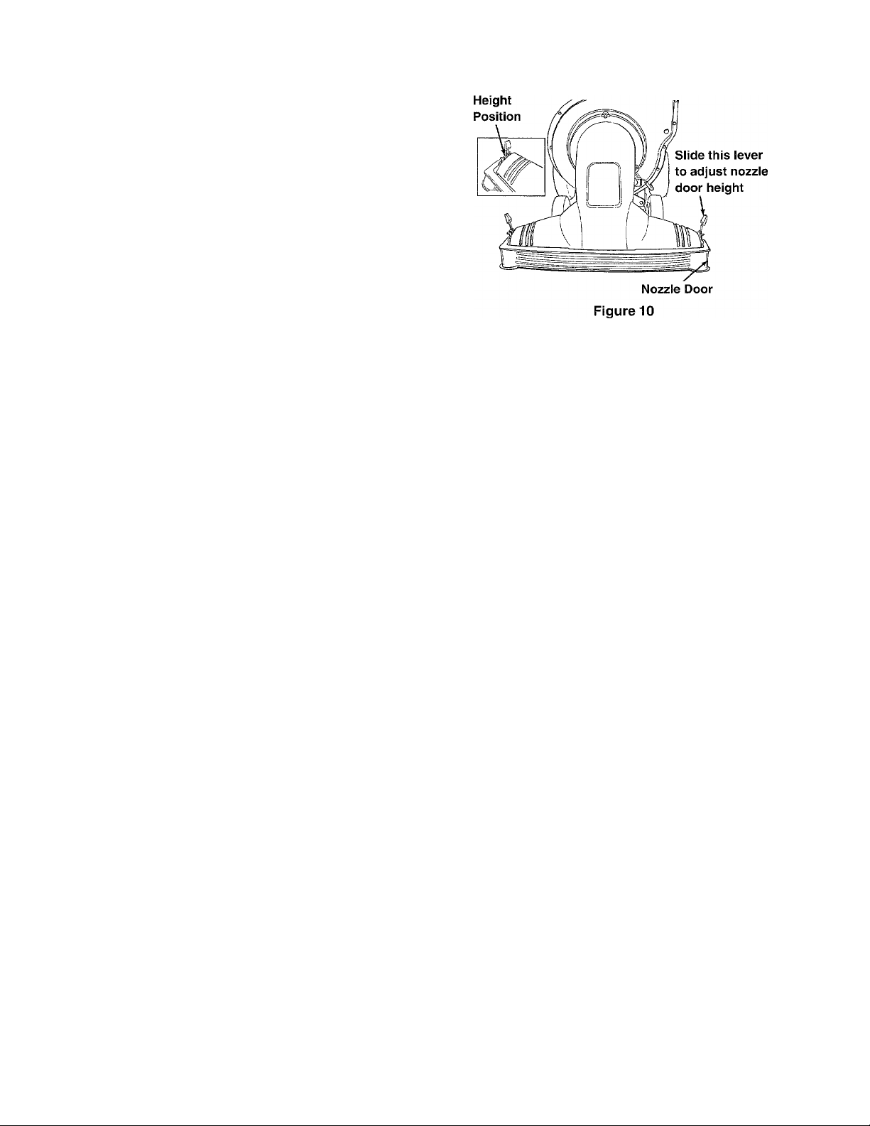
Adjusting Nozzle Height
• The nozzle door height adjustment levers have
five position settings and are found each side of
the nozzle door. See Figure 10. The nozzle door
height should be adjusted according to the
conditions.
• Slide the height adjustment lever forward or
backward for adjusting the nozzle door upwards
or downwards. See Figure 10.
WARNING: Keep your hands, feet and
any loose clothing clear of the nozzle any
A
time the engine is running. When the
engine is running, a vacuum is being
created in the nozzle which can draw in
loose clothing.
WARNING: Never make any adjustments
on the nozzle while the engine is running.
A
NOTE: Raise the nozzle height to vacuum a thick
layer of lea ves; lower the nozzle height for smoother
lawns.
Operation of your
Chipper-Shredder Vacuum
Your chipper-shredder vacuum is designed to chip
small tree branches and twigs, shred leaves and
vacuum foliage and other lawn debris. For
convenience in operation, your Craftsman chippershredder vacuum is equipped with a drive clutch
control allowing it to "self-propel."
WARNING: The impeller (chipping/
shredding mechanism) is rotating at all
A
A
IMPORTANT: Your chipper-shredder vacuum is
equipped with a safety switch at the front left portion
of the impeller housing. The metal tab on the nozzle
must depress this switch for the engine to start. Be
certain the nozzle is properly in place before
attempting to start the unit. See Figure 4 on page 6.
A
times when the engine is running.
WARNING: Keep your hands away from
the nozzle opening and NEVER place your
hands or arms inside of the chipper chute
when the engine is running. Doing so could
result in serious personal injury.
WARNING: Always survey the area to be
vacuumed thoroughly before operating the
chipper-shredder vacuum. Clear the area
of any obstructions such as toys, dog
chains, etc. Running over such an
obstruction can result in personal injury as
well as damage to the chipper-shredder
vacuum.
Do not vacuum up anything other than normal
yard waste such as leaves or pine needles.
10
Page 11
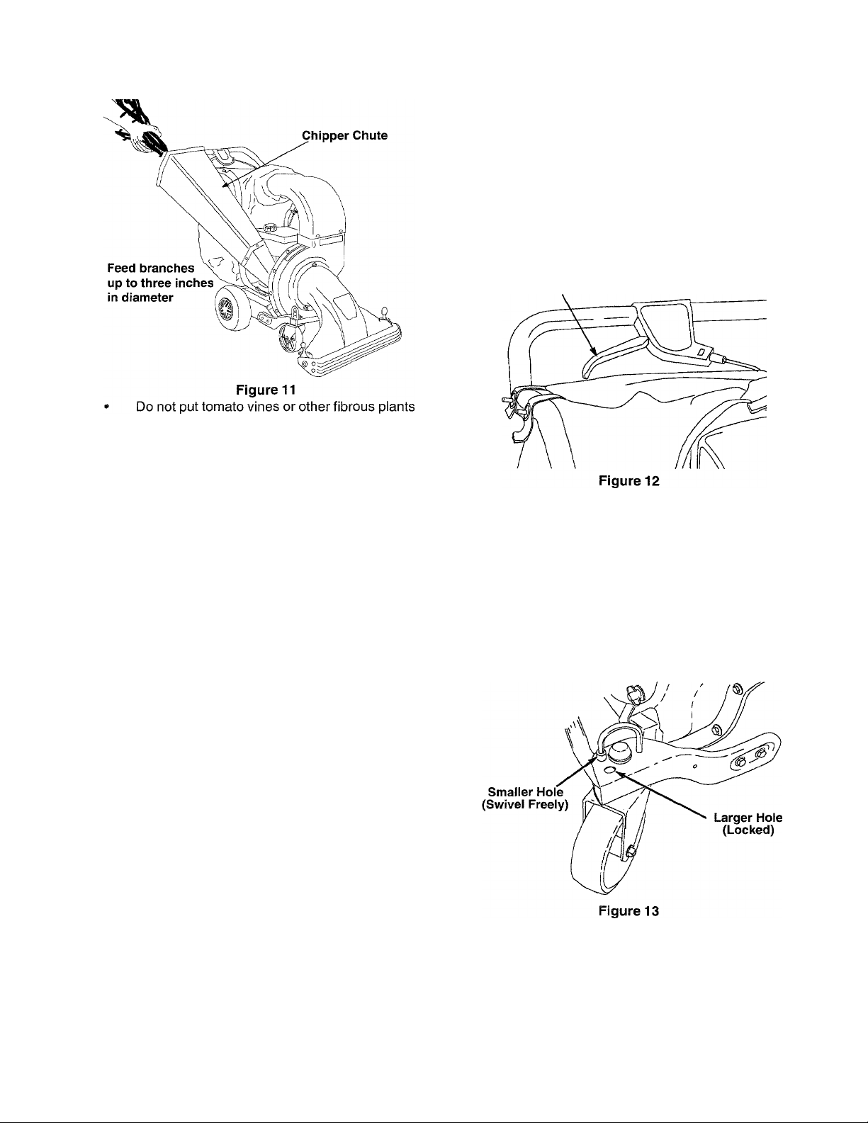
into the chipper chute unless it is thoroughly
dried out. Do not place any material other than
normal yard waste such as leaves, twigs or
branches up to three inches in diameter into the
chipper chute. See Figure 11.
Drive Clutch Control
Squeezing the drive clutch control engages the drive
mechanism to the rear wheels and causes the
chipper-shredder vacuum to self-propel. Release the
drive clutch control slightly to slow down the chippershredder vacuum’s ground speed when negotiating
an obstacle or making a turn. Release the drive clutch
control completely to stop the rear wheels from
driving. See Figure 12.
Drive Clutch
Control
WARNING: Personal injury and/or
dk
• For best performance, keep the chipper blades
• If the discharged material starts to become
• If the flail screen, located inside the housing in
NOTE: Care should be taken not to shut off the
damage to the unit could result if you try to
feed any material other than specified.
sharp.
stringy, or if the rate of discharge slows down
considerably, the chipper blades may have
become dull. To sharpen or replace the blade,
refer to Service and Adjustment section on
page 15.
the discharge area, becomes clogged, remove
the screen and clean. For instructions on
cleaning the screen, refer to the Service and
Adjustment section on page 15.
engine or to run out of gasoline while operating the
chipper-shredder.
• Check the fuel level periodically to avoid running
out of gasoline.
• To eliminate the possibility of jamming, never
turn engine off until all chipping is completed.
If the unit runs out of gas or is turned off as it is
shredding or chipping, it may be necessary to unciog
the unit before it can be restarted. Refer to “Removing
the Flail Screen” in Service and Adjustment section
on page 15.
Front Caster Wheels
Your chipper-shredder vacuum is equipped with
caster front wheels. The casters can be locked in a
straight ahead position or can be left to swivel freely.
• Lift and place pins in the larger holes for locked,
straight ahead operation. Place pins in smaller
holes to allow casters to rotate freely for more
manueverability. See Figure 13. Lock wheels in
straight position when operating on slopes.
11
Page 12
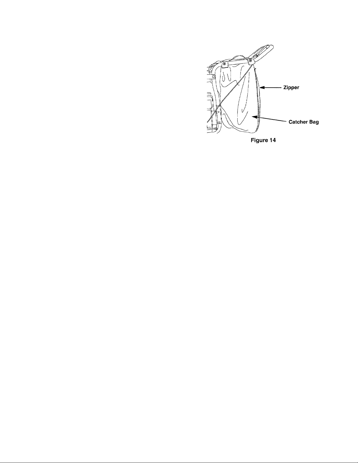
Catcher Bag
• To empty the catcher bag, open the large zipper
on the left side of the catcher bag and remove
the shredded debris from it. See Figure 14.
WARNING: Never operate your chippershredder vacuum without the catcher bag
A
A
properly in place. Doing so can result in
personal injury.
WARNING: Always make certain the
catcher bag is zipped closed before
operating the chipper-shredder vacuum.
Not doing so can result in personal injury.
12
Page 13
MAINTENANCE
General Recommendations
• Always observe safety rules when performing
any maintenance.
« The warranty on this chipper-shredder vacuum
does not cover items that have been subjected to
operator abuse or negligence. To receive full
value from the warranty, operator must maintain
the equipment as instructed in this manual.
• Some adjustments will need to be made
periodically to maintain your equipment properly.
• All adjustments in the Service and Adjustments
section on page 15 of this manual should be
checked at least once each season.
• Follow the maintenance schedule given below.
• Periodically check all fasteners and make sure
these are tight.
WARNING: Always stop the engine and
dk
disconnect the spark plug wire before
performing any maintenance or adjustments.
Lubrication
• Lubricate pivot points on the nozzle door height
adjustment levers according to chart below using
a light oil.
• Apply grease gun to the lube fittings found on the
front caster wheels according to chart below.
Cleaning
• Clean the chipper-shredder vacuum thoroughly
after each use.
• Wash the bag periodically with water. Allow to dry
thoroughly in the shade. Do not use heat.
Customer Responsibilities
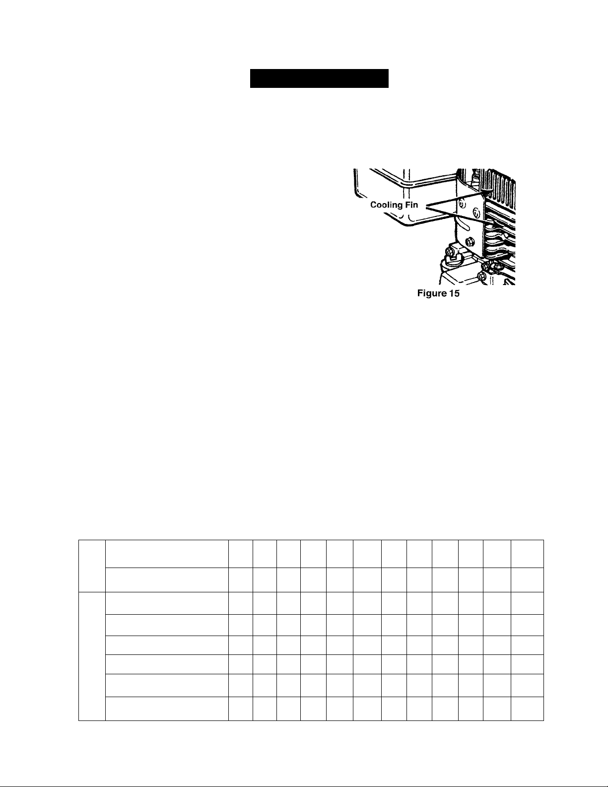
Clean engine periodically. Remove dirt and
debris with a cloth or brush.
Frequently remove grass clippings, dirt and
debris from cooling fins (see Figure 15), air intake
screen and levers and linkage. This will help
ensure adequate cooling and engine speed.
• Yearly or every 25 hours, whichever occurs first,
remove the blower housing and clean it to avoid
overspeeding, overheating and engine damage.
Clean more often if necessary.
NOTE: Cleaning with a forceful spray of water is not
recommended as it could contaminate the fuel system.
Change Engine Oil
• Only use high quality detergent oil rated with API
service classification SF, SG or SFI. Select the
oil’s viscosity grade according to your expected
operating temperature. Refer to page 9 of this
manual for viscosity chart.
Maintenance Schedule
t-
o
Lube pivot points & casters
Z3
a
o
cc
Clean equipment
a.
Check engine oil </
Change engine oil
lU
z
Service air cleaner
o
z
UJ
Service spark plug
Service muffler
Clean engine
/
/
❖
/
13
Record service dates here
Page 14
• Stop engine and wait several minutes before
checking oil level. With engine on level ground,
the oil must be to FULL mark on dipstick,
• Change engine oil after the first five hours of
operation, and every twenty-five hours
thereafter.
To Drain Oil
Drain oil while engine is warm. Follow the instructions
given below.
• Remove oil drain plug from the left side of the
engine and allow oil to run out into a suitable
container.
• When engine is drained of all oil, replace drain
plug securely.
• Refill with approximnately 20 oz. of fresh oil.
Refer to GAS AND OIL FILL-UP section.
• Replace dipstick.
c. Wrap in a clean cloth and squeeze (do not
twist) until completely dry, or allow to air dry.
d. Saturate with engine oil and squeeze (don’t
twist) to distribute oil. Remove excess oil.
e. Replace pre-cleaner making sure that the
screen side is towards the paper element.
NOTE; If the pre-cleaner is torn or damaged in any
way, replace it.
• If necessary, replace paper filter (do not attempt
to clean). Install new filter on base.
• Slide pre-cleaner over filter.
• Install cover and wing nut.
• Tighten wing nut securely.
WARNING: Temperature of muffler and
A
nearby areas may exceed 150° F(65°C).
Avoid these areas.
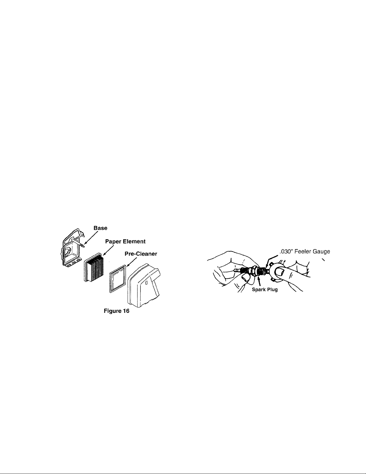
Air Cleaner
The air cleaner prevents damaging dirt, dust, etc.,
from entering the carburetor and being forced into the
engine and is important to engine life and
performance. The air cleaner consists of a pre
cleaner or foam filter, and a paper filter. See Figure
16. Never run the engine without air cleaner
completely assembled.
Wing
Nut
To Service Air Cleaner:
1. Service pre-cleaner after every 25 hours of use,
or at least once a season.
2. Service filter every 100 hours of use, or at least
once a season.
3. Service pre-cleaner and filter more often under
dusty conditions.
• Remove wing nut and cover. See Figure 16.
• Slide pre-cleaner off filter. Clean the inside of
base and cover thoroughly.
• Clean pre-cleaner as follows;
a. Wash in water and detergent solution, and
squeeze (do nottwist) until all dirt is removed.
b. Rinse thoroughly in clear water.
Spark Plug
• Clean the spark plug and reset the gap to .030"
at least once a season or every 50 hours of
operation. See Figure 17. Spark plug
replacement is recommended at the start of
each season. Refer to engine parts list for
correct spark plug type.
NOTE: Do not sandblast spark plug. Sparkplug
should be cleaned by scraping or wire brushing and
washing with a commercial solvent.
Figure 17
Servicing Muffler
• Inspect muffler periodically, and replace if
necessary.
• If your engine is equipped with a spark arrester
screen assembly, remove after every 50 hours
of use for cleaning and inspection. Replace if
damaged.
WARNING: Do not operate the chippershredder vacuum without a muffler or
dk
tamper with the exhaust system. Damaged
mufflers or spark arresters could create a fire
hazard.
14
Page 15
SERVICE & ADJUSTMENTS
Removing Flail Screen
If the discharge area becomes clogged, remove the
flail screen and clean area as follows.
• Stop the engine. Make certain the chippershredder vacuum has come to a complete stop.
Disconnect the spark plug wire before
unclogging the discharge chute.
• Remove the catcher bag from the unit.
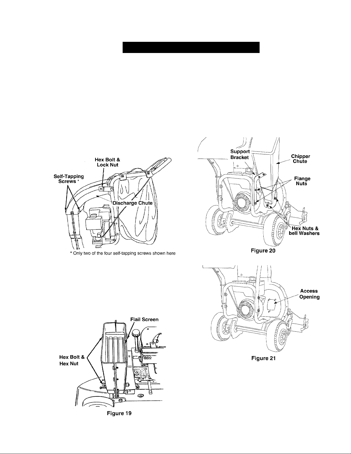
• Remove hex bolt and lock nut from the top side
section of the discharge chute. See Figure 18.
• Remove the four self-tapping screws from the
bottom of the discharge chute. (Be careful not to
drop the hardware into the chute.) Remove the
discharge chute. See Figure 18.
Servicing Chipper Blades
• Disconnect the spark plug wire and move it
away from the spark plug. Remove the flail
screen as instructed in the previous section.
• Remove the two flange nuts which secure the
support bracket to the handle assembly. Follow
by removing the three hex nuts and bell washers
which secure the chipper chute to the impeller
housing. See Figure 20
• Remove the chipper chute to allow access to the
impeller assembly. See Figure 21.
Figure 18
• Remove the two hex bolts and hex nuts which
extend through the housing. Lift the flail screen
from inside the housing. See Figure 19.
• Clean the screen by scraping or washing with
water. Reinstall the screen.
NOTE: Be certain to reassemble the flail screen with
the curved side DOWN.
15
A
WARNING: Make sure to wear heavy duty
gloves for this job. While accessing the
chipper blade, you may have to clean the
screw head of dust and shredded particles to
enable the alien wrench to operate.
the wrench carefully so that you do not
cut your hand on the chipper blade.
Handle
Page 16

• Locate one of the chipper blades in the access
opening by rotating the impeller by hand.
• Remove the blade using a 3/16" alien wrench on
the outside of the blade and 1/2" wrench on the
impeller assembly, inside the housing. Torque
hardware to 250/300 inch pounds.
• Remove the other blade in the same manner.
Replace or sharpen blades.
• If sharpening, make certain to remove an equal
amount from each blade.
• Reassemble following above instructions in
reverse order.
NOTE: Make sure that the blades are reassembled
with the sharp edge facing upward, as viewed from
the access plate opening.
Adjusting Carburetor
WARNING: If any adjustments are made to
A
The carburetor has been pre-set at the factory and
should not require adjustment. If your engine does
not operate properly due to suspected carburetor
problems, take your chipper-shredder vacuum to your
nearest SEARS service center.
the engine while the engine is running (e.g.
carburetor), keep clear of all moving parts.
Be careful of heated surfaces and muffler.
Drive Clutch Cable Adjustment
Adjust the drive clutch control if you notice the
following:
a. The chipper-shredder-vacuum moves
forward with the drive clutch control
disengaged.
b. The chipper-shredder-vacuum does not
self-propel with the drive clutch control
engaged.
c. The drive belt is slipping (unit hesitates
while engine maintains the same speed).
• Use the adjustment wheel located in the clutch
control housing to tighten or loosen (slack) in the
drive cable. See Figure 22 .
• In addition, the adjustment wheel may also be
used to determine the position in which the drive
clutch control is engaged. If it is more
comfortable to have the drive engaged with the
lever further away from the handle, tighten (take
up slack) in the drive cable.
Engine Speed
The engine speed on your chipper-shredder vacuum
has been set at the factory. Do not attempt to
increase the engine RPM. If you think that the engine
is running too fast or too slow, take your chippershredder vacuum to the nearest SEARS service
center for repair and adjustment.
WARNING: Do NOT attempt to alter the
A
engine speed by tampering with the engine’s
governor linkage. Doing so could result in
serious personal injury and damage to the
engine. The engine RPM has been set at the
factory.
Figure 22
Replacing Transmission Drive Belt
Do not attempt to replace the transmission drive belt
on your chipper-shredder vacuum. Special tools are
required. In the event you need to have the belt
replaced, take the unit to the nearest SEARS service
center.
16
Page 17

OFF-SEASON STORAGE
Prepare your Craftsman chipper-shredder vacuum
for storage at the end of the season or if the unit wiii
not be used for 30 days or longer. A yeariy check-up
by your iocai Sears service center is a good way to
ensure that the unit runs properly next season.
Chipper-Shredder Vacuum
• Clean the equipment thoroughiy.
• Wipe equipment with an oiled rag to prevent
rust. Use a light oil or silicone to wipe.
• Service the engine following instructions below.
• Store unit in a clean, dry area. Do not store next
to corrosive materials such as fertilizer.
Engine
IMPORTANT: It is important to prevent gum deposits
from forming in essential fuel system parts such as
the carburetor, fuel filter, fuel line, or gas tank during
storage. Also, experience indicates that alcohol
blended fuels (called gasohol or using ethanol or
methanol) can attract moisture which leads to
separation and formation of acids during storage.
Acidic gas can damage the fuel system of an engine
while in storage.
• Drain the fuel tank.
• Start the engine and let it run until the fuel lines
and carburetor are empty.
• Drain carburetor.
• Never use engine or carburetor cleaner
products in the fuel tank or permanent damage
may occur.
NOTE: Fuel stabilizer is an acceptable alternative in
minimizing the formation of fuel gum deposits during
storage.
• Add stabilizer to gasoline in fuel tank or storage
container.
• Always follow the mix ratio found on stabilizer
container.
• Run engine at least 10 minutes after adding
stabilizer to allow the stabilizer to reach the
carburetor.
• Do not drain the gas tank and carburetor if using
fuel stabilizer. Drain all the oil from the
crankcase (this should be done after the engine
has been operated and is still warm) and refill
the crankcase with fresh oil.
• If you have drained the fuel tank, protect the
inside of the engine as follows.
• Remove spark plug, pour approximately 1/2
ounce (approximately one tablespoon) of engine
oil into cylinder and crank slowly to distribute oil.
• Replace spark plug.
Other
• Do not store gasoline from one season to
another.
• Replace the gasoline can if it starts to rust. Rust
and/or dirt in the gasoline will cause problems.
• Store unit in a clean, dry area. Do not store next
to corrosive materials, such as fertilizer.
NOTE: If storing in an unventilated or metal storage
shed, be certain to rustproof the equipment by coating
with a light oil or silicone.
17
Page 18

TROUBLE-SHOOTING
Problem Possible Causes
Engine fails to start
Loss of power, erratic operation
Engine overheats
Too much vibration
Fuel tank empty, or stale fuel.
Spark plug wire disconnected.
Faulty sparkplug.
Nozzle safety switch not depressed.
Spark plug wire loose.
Blocked fuel line or stale fuel.
Water or dirt in fuel system.
Carburetor out of adjustment.
Dirty air cleaner.
Carburetor not adjusted
Engine oil level low.
Loose parts or damaged impeller
Corrective Action
Fill tank with clean, fresh fuel.
Connect wire to spark plug.
Clean, adjust gap or replace.
Adjust metal tab so it depresses the
safety switch.
Connect and tighten spark plug wire.
Clean fuel line; fill tank with clean, fresh
gasoline.
Disconnect fuel line at carburetor to
drain fuel tank. Refill with fresh fuel.
Contact your local Sears service
center.
Service air cleaner following
instructions on page 14.
Contact your local Sears service
center.
Fill crankcase with proper selection of
oil.
Stop engine immediately, disconnect
spark plug wire, tighten all bolts and
nuts and make necessary repairs. If
vibration continues, consult with your
local Sears service center.
Unit does not discharge
Rate of discharge slows considerably
or composition of discharged material
changes
For repairs beyond the minor adjustments listed above, please contact your local Sears service center.
Discharge chute clogged
Foreign object lodged in impeller.
Vacuum bag is full.
Dull chipper blades
Clean flail screen and blower housing
following instructions on page 15.
Stop engine immediately, disconnect
spark plug wire, and remove lodged
object.
Empty the bag.
Sharpen or replace blades following
instructions on page 15.
18
Page 19

PARTS LIST
Sears Craftsman 6.5 H.P. Chipper-Shredder Vacuum Model 247.77763
KEY
NO.
1 631 -0086
2
3 710-0969 Screw, Truss Hd Tapp
4 720-0190 Knob, Height Adj. 2
5 731-1831 Flap, Nozzle Rear 1
6
7 732-0754 Spring Lever
8
9 738-0913
10 781-0702 Bracket, Door Index RH
11
12 764-0522 Bag, 3 Bushel 1
13 731-1838A
PART
NUMBER
Nozzle Assembly Complete
(Includes Keys 2-11)
631-0049 Door Assembly, Black 1
631-0085
736-3084
781-0703
Nozzle, Black, w/ Switch Bracket 1
Washer, Flat, .510 x 1.20 x .060 2
Screw, Shoulder, .50 x 5/8-16
Bracket, Door Index LH
Discharge Chute
DESCRIPTION QTY.
19
1
2
2
2
1
1
1
Page 20

Sears Craftsman 6.5 H.P. Chipper-Shredder Vacuum Model 247.77763
Page 21

Sears Craftsman 6.5 H.P. Chipper-Shredder Vacuum Model 247.77763
KEY
NO.
1
2 681-0097A
3
4
5 710-0805 Screw, Hex Cap, 5/16-18 x 1.5 1
6
7 710-0604
8
9 710-0896
10 710-1331 Screw, Phil Cntrsnk, #10-16 x 1.25
11
12 711-0737
13 712-0138 Nut, Hex, 1/4-28 1
14 712-3004A Nut, Hex Flange Lock, 5/16-18 GR5
15 719-0359 Adapter, Engine Mtg 1
16
17 731-0620
18 731-1059
19 731-1646 Belt Cover 1
20 731-1735 Upper Clutch Cover 1
21 731-1736 Lower Clutch Cover
22 736-0329 Washer, Lock, 1/4
23 736-0451 Saddle Washer, .320 x .93 7
24 736-3008 Washer, Flat, .344 x .75 x .12
25 741-0413 Bearing, Flange, .631 ID x .72 OD 2
26 746-0714 Cable, Clutch, 56.0
27 747-0815 Eye Bolt
28
29 749-0980
30 749-0996 Handle, Upper
31
32
33 781-0700 Bracket, Axle 2
34 681-0087
35
36
37 732-0306 Spring, Compression
38
39 736-0366 Washer, Flat, .64 x 1.12 x .12
40
41 737-3000 Fitting, Lube, 3/16
42 741-0487A
43
44 734-1804
45 750-1042
46
47
48 712-0431
PART
NUMBER DESCRIPTION QTY
1539-019 Nut, Push, .25
Frame Assembly
710-0157
710-3180 Screw, Hex Cap, 5/16-18 x 1.75 6
710-0502A
710-0841
710-3008 Screw, Hex Cap, 5/15-18 x .75 GR5 3
725-0157 Cable Tie
747-0929A
781-0647
781-0697
714-0104
726-0214
736-0264
736-0931
747-0924
710-0521
681-0088
Screw, Hex Cap, 5/16-24 x .75 1
Screw, Hex Wash Hd Tapp,
3/8-16 X 1.25
Screw, Hex Wash Hd Tapp, 5/16-18 x .62 4
Screw, Phil Cntrsnk, #10-12 x .75
Screw, Hex Wash Hd, 1/4-14 x .62
Pin, Stud, .250 X 1.75 4
Lever, Drive Control 1
Cap, Cable Mtg 1
Belt Keeper 1
Handle, Lower
Bracket, Chute Stabilizing 1
Transmission Cover 1
Bracket Assembly, Front Wheel 1
Pin, Internal Cotter
Cap, Push, 5/8
Washer, Flat, .330 x .630 x .06 2
Washer, Flat, .203 IDx.403 OD .040 2
Bearing, Flange, .632 ID
Pin, Front Wheel Lock 2
Wheel, 6.00 x 2.00 2
Spacer, .384 ID x .5 OD x 2.3 Lg 2
Screw, Hex Cap, 3/8-16 x 3.0 2
Bracket Assembly, Pivot Wheel 2
Nut, Hex Flange Lock, 3/8-16
4
1
4
3
3
2
10
2
1
1
1
1
1
1
1
2
2
2
4
2
4
2|
21
Page 22

Sears Craftsman 6.5 H.P. Chipper-Shredder Vacuum Model 247.77763
KEY
NO.
2 710-1273
3 736-0217
4 736-0247
5
10
11 736-0119
PART
NUMBER
1 681-0108
681-0107
711-0833B Pin, Clevis
6
7 710-1054
712-0411
8
9 715-0166
719-0329
DESCRIPTION QTY.
Impeller Ass’y (Includes Keys 5-13)
Screw, Hex Cap, 3/8-24 x 2.75 GR5 1
Washer, Lock, 3/8 Heavy Duty
Washer, Flat, .406 x 1-1/4 HD 1
Impeller 1
Screw, Flat Hd. Cap, 5/16-24 x 1.0 4
Nut, Hex Insert Lock, 5/16-24
Pin, Spirol,.156x1.000 Std.
Blade, Flail 3
Washer, Lock, 5/16
12 781-0490 Blade, Chipper
—
781-0735
Clip, Retainer (Not Shown) 3
1
1
3
4
3
4
2
KEY
NO.
10
11 781-0780
PART
NUMBER
681-0068
1
710-0751 Hex Cap Screw
2
712-3010
3
712-3027 Hex Flange Nut, 1/4-20
4
728-0175
5
731-1574A Chipper Chute, Black
6
735-0249
7
736-0173 Flat Washer, .28 x .74 x .063
8
736-0242 Bell Washer, .34 x .872
9
Chipper Chute Assembly
Hex Nut, 5/16-18
Pop Rivet
Chute Flap
DESCRIPTION QTY.
781-0633 Chute Flap Strip
Chute Bracket
1
5
3
5
3
1
1
5
3
1
1
22
Page 23

Sears Craftsman 6.5 H.P. Chipper-Shredder Vacuum Model 247.77763
KEY
NO.
PART
NUMBER
1 781-0653
2 781-0627
3 781-0599
4 736-0119
5 731-1613
726-0272
6
7
725-3166
8 725-1700
9 723-0438
10 719-0326
712-3004A
11
DESCRIPTION
QTY.
Blade, Flail Housing
Cover, Chipper Blade
Blade, Upper Shredder 1
KEY
NO.
1
12
1 13
14 710-3008 Screw, Hex Cap, 5/16-18 x .75 2
PART
NUMBER
712-0421
Knob, 5/16-18 3
DESCRIPTION
712-0384 Nut, Hex Center Lock, 1/2-13 2
Washer, Lock, 5/16 3 15 710-1268 Screw, Wash Hd Tapp #10-16
Cover, Safety Switch Mtg.
Clamp
Switch, Snap Mount
Cover, Switch
Rubber Seal
Screen, Discharge
Nut, Hex Flange Lock, 5/16-18
1 16
1
1 18
1
2
1 21
4
710-0896 Screw, Wash Hd Tapp 1/4-14 1
710-0772 Screw, Hex Cap, 5/16-18x2
17
710-0604 Screw, Wash Hd Tapp 5/16-18
710-0382 Screw, Hex Cap, 1/2-13 x 5.0 2
19
20
681-0098
Housing Ass’y, Inner Flail
681-0060 Housing Ass’y, Outer Flail 1
629-0241A
22
Harness, Wire
23
QTY.
2
3
18
1
1
Page 24

Sears Craftsman 6.5 H.P. Chipper-Shredder Vacuum Model 247.77763
KEY
NO.
1
2
3 754-0457
4
5
6
PART
NUMBER
DESCRIPTION
781-0677 Chain Case LH
781-0676
Chain Case RH
V-Belt, 3/8 X 24.68
748-0313
741-0413
736-0336
Spacer, .630 x 1.25 x .29
Bearing, Hex Flange, .631 ID
Washer, Flat, 5/8 x 1.0
7 713-0422 Chain, Endless, #41 x 50 Inks
8 710-0896
9 710-0603
Screw, Hex Wash Hd,
Screw, Hex Wash Hd Tapp
5/16-18 x .5
10 618-0256
Trans. Assembly Complete
11 611-0063 Shaft Assembly, Axle
12 10662B Spring, Plastic Ratchet
QTY.
1
1
1
KEY
NO.
13
PART
NUMBER
DESCRIPTION QTY.
634-0136 Wheel Assembly, Complete
634-0129
Ratchet Rim Ass’y, Complete 2
734-0210 Tire, Pneumatic, 10x4
2 734-0255 Valve, Tubeless Air
2
2
14
1
15
7 16
2 17
18
1
1
19
4
20
741-0487A
712-0456
712-3027 Nut, Hex Flange Lock, 1/4-20
714-0104 Pin, Internal Cotter
736-0366
748-0188B
748-0381
748-0405
734-1984
Bearing, Flange, .632 ID
Nut, Special Hex 1/4-20 4
Washer, Flat, .64 x 1.12 x .12
Pawl, LH .345 ID
Pawl, RH .345 ID (Not Shown) 2
Ratchet, Wheel, .5 Serr ID x 1.62
Hubcap, 4.0
24
2
2
2
4
4
2
4
2
2
2
Page 25

Sears Craftsman 6.5 H.P. Chipper-Shredder Vacuum Model 247.77763
24
KEY
NO.
1
PART
NUMBER
DESCRIPTION QTY.
618-0255 Transmission Assembly, Complete
Includes Ref. Nos. 2 thru 20
2 16500A
3 711-1118
Hex Bearing Cup 1
Shaft, Output w/ 6T Sprocket 1
4 717-1432 Gear, Helical 34T
5 721-0213 Seal, Oil, .625 X.812
736-0187 Washer, Flat, .64 x 1.24 x .06 HD
6
7 736-0336
8 741-0413
Washer, Flat, 5/8 x 1.0 2 25 712-0138
Bearing, Hex Flange, .631 ID
9 741-0414 Bearing, Flange, .629 ID
10 741-0415 Bearing, Flange, .566 ID
11
719-0325
12
748-0373
13 719-0324A
Housing, Lower 1
Bearing, Flange, .503 ID
Housing, Upper 1 31 738-0440 Shoulder Spacer, .375 x .165 1
14 748-0208A Bearing, Flange, .378 ID
15 710-0589
16 717-1433
17
721-0329
18 736-0314
Screw, Hex Tapp, #10-16 x .75 3 33
Shaft, Pinion 10T 1
Seal, Oil, .50 X .687 1 35
Washer, Thrust, .382 x .684 2
KEY
NO.
1
19 736-0520
20
21
PART
NUMBER DESCRIPTION QTY.
Washer, Flat, .504 x .70 x .030
741-0479
Bearing, Thrust, .375 x .812 1
656-0008 Pulley Ass’y, Idler w/ Bearing, 1
Includes Ref. No. 22
1 22
1
1
741-0556 Bearing, Needle, .375 x .375
23 710-0589 Screw, Hex Tapp, #10-16 x .75 1
24 710-1062
Screw, Hex w/ Patch, 1/4-20 x 1.25 1
Nut, Hex. 1/4-28
1
26
712-3045 Nut, Hex Jam, 5/16-24 L.H. Thd 1
1
27 732-0357A Spring, Extension, 1.12 Lg 1
1 28 736-0270 Washer, Bell, .265 x .75 x .06 1
29
1
30
1 32
736-0329
736-0425 Washer, Bell, .325 x .930 x .045
738-0826
Washer, Lock, 1/4
Shoulder Bolt, 1/4-28 x .375 1
756-0618 Pulley, Flat, 5.06 Dia 1
34
782-7569 Belt Keeper
782-7570
Bracket, Idler
25
1
1
1
1
2
1
1
Page 26

Sears Craftsman 6.5 H.P. Engine Model No. 143.986501
for Chipper-Shredder Vacuum Model 247.77763
279 161
V" 161A /
26
Page 27

Sears Craftsman 6.5 H.P. Engine Model No. 143.986501
for Chipper-Shredder Vacuum Model 247.77763
KEY
NO.
1
PART
NUMBER
37120A
Cylinder (Incl. 2)
2 26727 Dowel Pin
4 31857
5 30969
14 651052
15 37108
16 37110
30 36831
35 651053
37 29216
38 37109
40 40004
40005
41 36070
36071
42 40006
Oil Drain Extension
Extension Cap 154 650913 Rocker Arm Stud
Washer
Governor Rod
Governor Lever
Crankshaft 159 35626 Rocker Arm Cover Gasket
Screw, TorxT-15, 10-32 x 63/64"
Lock Nut, 10-32 161
Retaining Ring
Piston, Pin & Ring Set (Std.) 173
Piston, Pin & Ring Set (.010" OS)
Piston & Pin Ass'y (Std.) (Incl. 43) 182
Piston & Pin Ass'y (.010" OS) (Incl. 43) 184 26756 Carburetor To Intake Pipe Gasket
Ring Set (Std.)
DESCRIPTION
KEY
NO.
150
151 31673 Valve Spring Cap
153
155
157 650914 Nut, 1/4-28
158
160
161A
178
185
40007 Ring Set (.010" OS) 207
43 20381
45
46
32875A Connecting Rod Ass'y (Incl. 46 & 49) 224 36581 Intake Pipe Gasket
3261OA
48 35616
49 36611
50
37040
64 651015 Screw, 1/4-20 X 1-1/8"
69 36624
70 36625
75
80
27897 Oil Seal
30574A
81 30590A
82 30591
83
36057
86 650488
89 610961
119 36719
120
36721 Cylinder Head
Piston Pin Retaining Ring 223
Connecting Rod Bolt
Valve Lifter
Oil Dipper
Camshaft
238
239
240
245 36046
245A
Cylinder Cover Gasket
250
Cylinder Cover (Incl. 75 thru 83) 250A
251
Governor Shaft 252
Washer
Governor Gear Ass'y (incl. 81)
Governor Spool
275
277 650988 Screw, 1/4-20 x 2-9/32"
278
Screw, 1/4-20 X 1-1/4" 279
Flywheel Key
280 36893
Cylinder Head Gasket 305
307
125 36471 Exhaust Valve (Std.) (Incl. 151) 308
36472 Exhaust Valve (1/32" OS) (Incl. 151)
310
126 29314C Intake Valve (Std.) (incl. 151) 380
29315C
130
130A
650912 Screw, 5/16-18 x 1-1/2"
650999
135 34645
Intake Valve (1/32" OS) (incl. 151)
Screw, 5/16-18x2-41/64"
Resistor Spark Plug (RN4C)
390
400 36720 Gasket Set
PART
NUMBER
DESCRIPTION
37039 Valve Spring
36649 Push Rod Guide
35624A
Rocker Arm
36629 Push Rod
36630A Rocker Arm Cover
651008 Screw, 1/4-20 X 31/64"
651012
Stud
36675A Breather Tube
650852
Nut, 1/4-20
650451 Screw, 1/4-20 x 1"
36631 Intake Pipe
36632
Throttle Link
650451 Screw, 1/4-20 X 1"
28820 Screw, 10-32 X 1/2"
27272A Air Cleaner Gasket
36633A Air Cleaner Body (Incl. 239)
Air Cleaner Filter
36634 Air Cleaner Filter (Poly)
37073
Air Cleaner Cover
37074 Air Cleaner Baffle
650886 Wing Nut
650821
36722
36674
650852
Screw, 10-32 X 1/2"
Muffler
Spacer
Nut & Lock Washer
Heat Shield
35554 Oil Fill Tube
35499
"0" Ring
37079 Fill Tube Clip
36902 Dipstick
640025B
590736
— 754299A Replacement Short Block (Not Shown)
Carburetor (Incl. 184)
Rewind Starter
27
Page 28

Sears Craftsman 6.5 H.P. Engine Model No. 143.986501
for Chipper-Shredder Vacuum Model 247.77763
KEY
NO.
1 37111
PART
NUMBER
DESCRIPTION
Extension Spring
2 32600 Oil Seal
3
4 36622
5
6
11
12 650815
36621 Air Baffle (Left) 30
Air Baffle (Right) 32
30200 Screw, 10-24x9/16" Thd. 33
36623A Blower Housing Extension
611205
Flywheel 35
Bell Washer 36 36863
13 650816 Flywheel Nut
14 34443B Solid State Ignition
15 610118
16 651007
Spark Plug Cover 40 29443
Torx Screw T-15,10-24 x 15/16" 41
17 36711 Governor Link
18
36054
Ground Wire
20 36736 Control Bracket
21
22
24
610973
650821
651008
Terminal 46
Screw, 10-32X 1/2"
Screw, 1/4-20x31/64"
KEY
NO.
26
28
PART
NUMBER
DESCRIPTION
36638 Control Knob
36864 Blower Housing
650821 Screw, 10-32 X 1/2"
35985B Starter Cup
— Rivet (Purchase Locally)
34 30705 Fuel Line
26460 Fuel Line Clamp
Fuel Tank
37 36246
38 34080
Fuel Cap
Spacer
Wire Clip
36644 Fuel Tank Bracket
42 651010 Screw, 1/4-20x7/8" Thd.
43 36261
Lubrication Decal
44 35703 Speed Control Decal
590736 Rewind Starter
—
36720 Gasket Set (Not Shown)
28
Page 29

Sears Craftsman 6.5 H.P. Engine Model No. 143.986501
for Chipper-Shredder Vacuum Model 247.77763
carburetor
KEY
NO.
—
1
2 631767
4 631184
5
6 631036
7
16
PART
NUMBER
640025B
631615
631183
650506
632164
DESCRIPTION
Carburetor
Throttle Shaft & Lever Assembly
Throttle Return Spring
Dust Seal Washer
Dust Seal (Throttle)
Throttle Shutter
Shutter Screw
Fuel Fitting
17 650417 Throttle Crack Screw/ldle Speed
18 630766
20 640018
631867
25
27 631024
28 632019
29 631028
631021 Inlet Needle, Seat, & Clip Inci. 31)
30
631022 Spring Clip
31
35 36045
Tension Spring
Restrictor Screw
Float Bowl
Float Shaft
Float
Float Bowl "0"-Ring
Primer Bulb/Retainer Ring
36 640019 Main Nozzle Tube
37 632547 ”0''-Ring, Main Nozzle Tube
40 640015
44
27110
47
630748
631027 Welch Plug, Atmospheric Vent
48
High Speed Bowl Nut
Bowl Nut Washer
Welch Plug, Idle Mixture Well
KEY
NO.
—
1
PART
NUMBER
590736
590599A
2 590600
3 590696
4
590601
5 590697
590698
6
7 590699
8 590700
11
590705
12 590535
590701
13
DESCRIPTION
Rewind Starter
Spring Pin (Inci. 4)
Washer
Retainer
Washer
Brake Spring
Starter Dog
Dog Spring
Pulley & Rewind Spring Assembly
Starter Housing Assembly
Starter Rope (98" x 9/64" diameter)
Starter Handie
rewind
starter
29
Page 30

For the repair or replacement parts you need
delivered directly to your home
Call 7 am - 7 pm, 7 days a week
1 -800-366-PART
(1-800-366-7278)
For in-home major brand repair service
Call 24 hours a day, 7 days a week
1-800-4-REPAIR
(1-800-473-7247)
For the location of a
Sears Parts and Repair Center in your area
Call 24 hours a day, 7 days a week
1-800-488-1222
For information on purchasing a Sears
Maintenance Agreement or to inquire
about an existing Agreement
call 9 am - 5 pm, Monday-Saturday
1 -800-827-6655
REPAIR SERVICES
America's Repair Specialists
Page 31

Manual del propietario
6.5 caballos de fuerza
Autopropulsada
Astiiladora-Desmenuzadora-Aspiradora
Modelos No.
247.777763
Precaución:
Antes de operar este
equipo lea y observe todas
las reglas e instrucciones
de seguridad
Sears, Roebuck and Co., Hoffman Estates, IL 60179, U.S.A.
Printed in U.S.A.
770-10034
(7/98)
Page 32

TABLA DE MATERIAS
Contenido
Garantía
Reglas de seguridad 3 Servicio y ajustes
Armado 5 Almacenamiento
Operación
Página
2 Mantenimiento
8 Tabla de localización de fallas
Contenido
Página
13
15
17
18
INFORMACION DE GARANTIA
GARANTIA COMPLETA DE UN ANO PARA LA ASTILLADORA-ASPIRADORA A GASOLINA CRAFTSMAN
Por un año desde la fecha de compra cuando esta astilladora-aspiradora a gasolina Craftsman sea mantenida, lubricada y
puesta a punto de acuerdo con las instrucciones de operación y mantenimiento en el manual del operario, Sears reparará
libre de costo cualquier defecto de material o de mano de obra.
Esta garantía excluye las cuchillas, desgranadoras, filtros, bujías, bolsas del retén y neumáticos, las cuales son partes
desechadles que se desgastan durante el uso normal.
Esta garantía se aplica por 30 días solamente a partir de la fecha de compra, si la astilladora-desmenuzadora se usa para
fines comerciales o de alquiler.
EL SERVICIO DE GARANTIA ESTA DISPONIBLE EN EL CENTRO DE SERVICIO DE SEARS MAS CERCANO EN LOS
ESTADOS UNIDOS.
Esta garantía le otorga derechos legales específicos y usted puede también tener otros derechos que varían de estado a
estado.
SEARS, ROEBUCK AND CO. DEPT. D817WA, HOFFMAN ESTATES, IL 60179
ACCESSORIOS
Estos accesorios y aditamentos
estaban disponibles cuando la
astilladora-aspiradora se
compró originalmente. Están
también disponibles en la
mayoría de las tiendas
minoristas y centros de
catálogo y servicio de Sears. La
mayoría de las tiendas de
Sears pueden ordenar esos
artículos para usted con el
número de modelo de su
astil ladora-aspi radora.
Caballos de fuerza
Capacidad de aceite de motor
Capacidad de combustible 3 cuartos (sin plomo)
Bujía Champion RN4C
Presión del neumático
Filtro
de aire
Bujía Aceite Recipiente Estabilizador Tapón del manauera^de
de motor de gasolina apisonador Jp¡radora
ESPECIFICACIONES DEL PRODUCTO
6.5 H P
SAE 30 (20 onzas)
24 P.S.I.
Número de modelo
Número de serie.
Los números de modelo y de serie se encuentran en el
rotulo.pegado al producto.
Usted debería registrar el número de serie y la fecha de
compra y guardarlos en un lugar seguro para referencia
futura.
247.77763
Page 33

PRACTICAS SEGURAS DE OPERACION
Este símbolo señala instrucciones importantes de seguridad las cuales, si no se observan, podrían poner en
peligro la seguridad personal y/o la propiedad suya y de otras personas. Lea y observe todas las instrucciones de
A
A
A
Operación general
• Lea cuidadosamente esta guía del propietario en su
totalidad antes de intentar armar esta máquina. Lea,
comprenda y observe todas las instrucciones en la
máquina y en el manual(es) antes de la operación.
Guarde este manual en un lugar seguro para referencia
futura y regular y para ordenar piezas de repuesto.
• Su astilladora-aspiradora es una herramienta poderosa y
no un juguete. Por consiguiente ejerza una precaución
extrema en todo momento. Su unidad ha sido diseñada
para desempeñar dos tareas; astillar y aspirar vegetación
hallada en un patio normal. No la use para ningún otro fin.
• Nunca permita que niños menores de 16 años operen la
unidad. Los niños de 16 años de edad y mayores deben
operar solamente bajo una supervisión paterna estrecha.
Debe permitirse operar la unidad a individuos
responsables que estén familiarizados con estas reglas
de operación segura solamente.
• Mantenga el área de operación despejada de todas las
personas, particularmente niños pequeños y animales
domésticos. Apague el motor cuando están cerca de la
unidad.
• Al alimentar material al equipo, sea extremadamente
cuidadoso que no se incluyan piezas de metal, rocas,
botellas, latas u otros objetos extraños. Podrían resultar
lesiones personales o daños a la máquina.
• Use siempre lentes de seguridad o anteojos de
seguridad, durante la operación y al efectuar ajustes o
reparaciones, para proteger los ojos contra objetos
extraños que pueden ser despedidos por la máquina.
• Use zapatos de trabajo resistentes, de suela áspera y
pantalones y camisa ajustadas. Se recomiendan camisas
y pantalones que cubran los brazos y las piernas y
zapatos de puntera de acero. No use ropas holgadas ni
este manual antes de intentar operar su astilladora-aspiradora motorizada. No cumplir con estas instrucciones
puede resultar en lesiones personales. Cuando vea este símbolo obedezca su advertencia.
Su astilladora-aspiradora fue fabricada para operarse de acuerdo con las reglas para una opera
ción segura en este manual. Al igual que con cualquier tipo de equipo motorizado, la falta de
PELIGRO ^cuidado o error de parte del operador puede resultar en lesiones graves. No observar las
instrucciones siguientes de seguridad podría resultar en lesiones graves o en la muerte.
El escape del motor de este producto contiene substancias químicas conocidas por el Estado de California como
causantes de cáncer, defectos de nacimiento u otras lesiones reproductivas.
Esta unidad está equipada con un motor de combustión interna y no debe usarse en o cerca de tierras no
mejoradas cubiertas de bosques, matorrales, y/o hierbas, a menos que el sistema de escape esté equipado con
un supresor de chispas que cumpla con las leyes del estado o federales aplicables (de existir). Si se usa un
supresor de chispas debe ser mantenido en buenas condiciones de trabajo por el operador.
En el Estado de California lo indicado arriba es requerido por ley (Sección 4442 del Código de Recursos Públicos
de California). Otros Estados pueden tener leyes similares. Las leyes federales se aplican en las tierras federales.
Está disponible un supresor de chispas para el silenciador en su Centro de Servicio Autorizado Sears más
cercano (Vea la sección de PIEZAS DE REPUESTO de este manual).
joyas y sujete el cabello para que esté por encima de los
hombros. Pueden quedar atrapadas en las piezas
móviles. Nunca opere una unidad con los pies descalzos,
sandalias o zapatillas. Al alimentar material en la canaleta
de la astilladora, use guantes.
• No opere la unidad mientras está bajo los efectos del
alcohol o las drogas.
• No se incline demasiado. Manténgase firmemente
parado y en equilibrio en todo momento.
• Nunca coloque sus manos o ninguna parte de su cuerpo
o ropas cerca de o debajo de piezas giratorias.
Manténgase alejado en todo momento de la abertura de
descarga. Nunca inserte sus manos ni ninguna parte de
su cuerpo ni ropa dentro de la boquilla, canaleta de la
astilladora o la abertura de descarga ya que la hélice
giratoria puede causar lesiones graves.
• Si por alguna razón es necesario destapar la toma de
alimentación o de la abertura de descarga o inspeccionar
o reparar cualquier parte de la máquina donde una pieza
móvil puede entrar en contacto con su cuerpo o ropa,
apague la máquina, permita que se enfríe, desconecte el
conductor de la bujía de la bujía y aléjela de la bujía antes
de Intentar destapar, inspeccionar o reparar.
• Nunca opere la unidad sin que la bolsa de la aspiradora y
la canaleta de descarga estén bien fijadas a la unidad.
Para evitar que los objetos grandes sean impulsados, el
extremo grande de cierre a cremallera de la bolsa debe
estar cerrado.
• Nunca opere la unidad sin que la boquilla de entrada o el
aditamento opcional de la manguera estén
apropiadamente fijados a la unidad. Esos mecanismos
protegen al operador contra el contacto accidental con la
hélice giratoria. Nunca trate de convertir la unidad del
modo de boquilla al de manguera o viceversa con el
motor funcionando.
Page 34

• Nunca trate de retirar ni vaciar ia bolsa de la aspiradora
cuando el motor está funcionando. Apague el motor y
espere hasta que la hélice se detenga completamente
antes de retirar la bolsa. La hélice continúa girando
durante unos segundos después de apagar el motor.
Nunca coloque ninguna parte del cuerpo en el área de la
hélice hasta que esté seguro que la hélice ha detenido
su giro.
• Mantenga todas las guardas y mecanismos de
seguridad en su lugar y operando apropiadamente.
• No permita una acumulación de material procesado en
el área de descarga ya que esto impedirá la descarga
apropiada y puede resultar en contragolpe de la
canaleta de la astilladora.
• Mantenga su rostro y cuerpo detrás de la canaleta de la
astilladora para evitar un rebote accidental del material.
• Si el mecanismo de corte golpea un objeto extraño o si
su máquina comienza a emitir un ruido o vibración no
común, apague inmediatamente el motor, desconecte el
conductor de la bujía y mueva el conductor alejado de la
bujía. Permita que la máquina se detenga y tome los
pasos siguientes.
• Inspeccione por daños.
• Repare o reemplace las piezas dañadas.
• Inspeccione por piezas flojas y ajuste para asegurar una
operación segura continuada.
• El silenciador y el motor se calientan y pueden causar
quemaduras. No los toque.
• No permita que hojas u otros desechos se acumulen
sobre el silenciador del motor. Los desechos podrían
encenderse y causar un incendio.
® No opere el motor si se retira el filtro de aire o la cubierta
sobre la toma del carburador, excepto para ajustar. El
retiro de tales piezas podría crear un riesgo de incendio.
Niños
Pueden ocurrir accidentes trágicos si el operador no está
alerta a la presencia de niños pequeños. Los niños se
sienten atraídos a menudo a la actividad de astillado y
aspiración. Nunca suponga que los niños permanecerán
donde usted los vio por última vez.
• Mantenga a los niños fuera del área de trabajo y bajo los
ojos vigilantes de un adulto responsable que no sea el
operador.
• Esté alerta y apague la unidad si un niño entra al área.
• Nunca permita que niños menores de 16 años de edad
operen la astilladora-aspiradora.
Permita que ei motor se enfríe por dos minutos por lo
menos antes de cargar combustible.
• Vuelva a colocar la tapa de gasolina y limpie la gasolina
derramada antes de arrancar ei motor, ya que puede
causar un incendio o explosión.
• Apague todos los cigarrillos, cigarros, pipas y otras
fuentes de encendido.
• Nunca cargue combustible a la unidad bajo techo ya que
los vapores inflamables se acumularán en el área.
• Nunca almacene la máquina ni el recipiente de
combustible bajo techo donde haya llamas abiertas o
chispas, tales como calentadores de agua caliente a
gas, secadora de ropas u hornos.
• Nunca haga funcionar su máquina en un área cerrada ya
que el escape del motor contiene monóxido de carbono,
que es un gas inodoro, insípido y envenenador mortal.
• Para reducir el riesgo, mantenga el motor y el silenciador
libre de hojas, césped, y otras acumulaciones de
desechos. Limpie los derrames de combustible y aceite.
Permita que la unidad se enfríe por 5 minutos por lo
menos antes de arrancar.
• Asegúrese que la hélice y todas las piezas móviles estén
detenidas antes de limpiar, reparar o inspeccionar.
Desconecte el conductor de la bujía y mantenga el
conductor alejado de la bujía para prevenir el arranque
accidental. No use soluciones inflamables para limpiar el
filtro de aire.
• Mantenga todas las tuercas, pernos y tornillos bien
ajustados para asegurarse que el equipo esté en buenas
condiciones de trabajo.
• Nunca manipule los mecanismos de seguridad.
Inspeccione regularmente su operación apropiada.
• Después de golpear un objeto extraño, apague
inmediatamente el motor, desconecte el conductor de la
bujía de la bujía, e inspeccione completamente la unidad
por daños. Repare el daño antes de arrancar y operar la
unidad.
• No altere ni manipule la graduación del regulador del
motor. El regulador controla la velocidad operativa
máxima del motor. Es peligroso hacer funcionar el motor
a una velocidad excesiva y causará daños al motor y a
otras piezas móviies de las máquinas.
• inspeccione frecuentemente la bolsa de la aspiradora
por desgaste. Reemplace si está gastada o dañada.
• Cuando no está en uso, mantenga la bolsa de la
aspiradora libre de desechos.
Servicio
Al usar gasolina y otros combustibles use un cuidado
extremo. Son extremadamente inflamables y los vapores
son explosivos.
• Almacene el combustible y aceite en recipientes
aprobados, alejados del calor y de las llamas abiertas,
fuera del alcance de los niños.
• Inspeccione y agregue combustible antes de arrancar el
motor. Nunca retire la tapa de gasolina ni vierta
combustible mientras el motor está funcionando.
ADVERTENCIA —su responsabilidad
Restrinja el uso de esta máquina motorizada a las personas que lean, comprendan y siguen las advertencias e
A
instrucciones en este manual y en la máquina.
Page 35

Parte
posterior
Derecha
INSTRUCCIONES DE ARMADO
IMPORTANTE: Esta unidad se despacha sin
gasolina o aceite en el motor. Para un llenado
apropiado de combustible y de aceite del motor,
Izquierda
Frente
Tolva de la astilladora
Ménsula de soporte
después del ensamblado, lea la sección de
OPERACION de este manual.
NOTA: Párese detrás de la unidad con el motor
alejado de usted, para determinar los lados derecho
e izquierdo de su astilladora-desmenuzadoraaspiradora.
Su astilladora-desmenuzadora-aspiradora ha sido
completamente ensamblada de fábrica, excepto por la
boquilla, la tolva de la astilladora con la ménsula de
soporte y la bolsa retenedora. Esas partes se envían
sueltas en la caja. Se incluyen también en la caja un par
de antiparras de seguridad y una botella de 20 oz. de
aceite de motor.
Extracción de la caja
• Corte las esquinas de la caja.
• Extraiga todas las inserciones de envase.
» Extraiga todas las piezas sueltas. Vea la figura 1.
* Presione sobre la manija para elevar el frente de la
astilladora-desmenuzadora-aspiradora y ruede la
unidad fuera de la caja.
® Antes de desechar la caja, asegúrese que ha
extraído todas las piezas y la literatura.
Aceite de motor
(20 onzas)
Piezas sueltas
(Vea la figura 1.)
1. Boquilla
2. Tolva de la astilladora con la ménsula de soporte
3. Bolsa
4. Antiparras de seguridad (no se muestran en la
figura 1)
5. Aceite de motor (20 onzas)
Figura 1
Herramientas requeridas
1. Llaves de 1/2" o ajustables
2. Llaves de 7/16" o ajustables
3. Embudo (recomendado)
4. Pinzas
Desconexión de la bujía
(Vea la figura 2.)
* Desconecte el cable de la bujía de la bujía en el
motor y aléjela, antes de proceder con el
ensamblado de su nueva unidad astilladoradesmenuzadora-aspiradora. Esto evitará el
arranque accidental del motor.
Page 36

Fijación de la boquilla
(Vea la figuras.)
• Extraiga las tres tuercas mariposa plásticas del frente de
laastilladora-desmenuzadora-aspiradora.
• Coloque la boquilla sobre los tres pernos prisioneros
soldados.
• Asegure con las tres tuercas mariposa plásticas recién
extraídas.
Tuercas mariposa
Figura 4
Fijación de la tolva de la astilladora
• Afloje, pero NO extraiga los dos pernos
hexagonales, arandelas planas y tuercas de unión
que están aseguradas a la ménsula de soporte.
Vea la figura 5.
NOTA: La aleta de metal en la boquilla debe
presionar el Interruptor de seguridad al frente de la
astilladora-desmenuzadora- aspiradora o el motor no
arrancará. Vea la figura 4.
Figura 5
Extraiga las dos tuercas de unión, pernos
hexagonales y arandelas curvas que aseguran el
lado derecho de la manija superior al lado derecho
de la manija inferior. Vea la figura 6.
A continuación, extraiga las tres tuercas
hexagonales y arandelas acampanadas de los
pernos prisioneros soldados ubicados al lado
derecho de la astilladora-desmenuzadoraaspiradora. Vea la figura 6.
Page 37

Coloque la tolva de la astilladora sobre los pernos
prisioneros soldados manteniendo el lado
ranurado hacia la parte inferior. Asegure
flojamente con las tres tuercas hexagonales y
tuercas acampanadas que se extrajeron antes. No
ajuste bien ias tuercas hexagonales en este
momento del ensamblado. Vea la figura 7.
» Alinee la ménsula de soporte con los orificios del
lado de la derecha de las manijas inferior y
superior, donde recién se extrajeron los pernos
hexagonales. Empuje ligeramente hacia arriba la
tolva de la astilladora para alinear mejor los
orificios en la ménsula de soporte con los orificios
en las manijas.
• Vuelva a colocar los pernos hexagonales,
arandelas curvas y tuercas de unión para fijar la
ménsula de soporte a los conjuntos de la manija.
Vea la figura 7.
• Continúe ajustando seguramente toda la ferretería
primero a la tolva de la astilladora, a continuación a
la ménsula de soporte y finalmente a la manija.
Fijación de ia bolsa retenedora
• Coloque la bolsa retenedora dentro del conjunto
de la manija. Deslice la abertura de la bolsa sobre
la canaleta de descarga, asegurándose que esté
sobre la costilla de la canaleta de descarga.
• Coloque las cuatro correas del tope de la bolsa
sobre la manija superior, enganchándolas en los
pernos prisioneros.
• Cierre la mordaza sobre el cordón y tire del mismo
hasta que esté tirante. Abra la mordaza. Vea la
figura 8.
Page 38

OPERACION
Conozca su astilladora-desmenuzadora
Refiérase a las “reglas de seguridad” según indicadas en la página 2 de este manual, antes de usar su astiliadora-aspiradora
sea siempre cuidadoso.
La operación de una astilladora-aspiradora puede resultar en que objetos extraños sean despedidos
contra los ojos, lo que puede lesionarlos gravemente. Antes de astillar, o mientras efectúe ajustes o
reparaciones, use siempre los anteojos de seguridad provistos con esta unidad o protectores de los
ojos. Recomendamos la máscara de seguridad Wide Vision sobre los anteojos o las antiparras estándar
disponibles en las tiendas minoristas de Sears.
Controles de operación
Tolva de la astilladora
Permite que ramitasy ramas pequeñas de hasta dos
pulgadas de diámetro sean alimentadas a la hélice para
desmenuzar.
Boquilla
Desechos de jardín tales como hojas y espinas de pino
pueden aspirarse por la boquilla.
Bolsa retenedora
Recoge material desmenuzado alimentado a través de la
tolva de la astilladora o aspirado a través de la boquilla.
Control del embrague del propulsor
El oprimir el control del embrague del propulsor causa que
la astilladora-desmenuzadora-aspiradora se autopropulse.
Puerta de la boquilla
La distancia al suelo de la boquilla puede ajustarse con la
puerta de la boquilla.
Ruedas metálicas delanteras
Permite una selección en la facilidad de maniobra de la
astilladora-desmenuzadora-aspiradora.
Cebador
El cebador se usa para asistir en arrancar un motor en frío o
volver a arrancar un motor después de un breve apagado.
Manija del arrancador
Se usa para arrancar el motor.
Control del regulador
Controla la velocidad del motor y apaga el motor.
Apagado del motor
• Mueva el control del regulador a la posición STOP.
• Desconecte el cable de la bujía y aléjelo de la bujía para
evitar un arranque accidental mientras el equipo está
desatendido.
Cumple con las normas de seguridad de ANSI
Las astilladoras-desmenuzadoras-aspiradoras de Craftsman conforme con las normas de seguridad
del American National Standards Institute (ANSI)
Page 39

Llenado de gasolina y aceite
Aceite (una botella de 20 oz. enviada con la unidad)
Use sólo aceite detergente de alta calidad clasificado
con la clasificación de servicio API de SF, SG, o SH.
Seleccione el grado de viscosidad del aceite de
acuerdo con la temperatura esperada de operación.
Siga la tabla de abajo.
NOTA: A pesar que los aceites de viscosidad
múltiple (5W30, 10W30, etc.) mejoran el arranque en
el tiempo frío, esos aceites de viscosidad múltiple
resultarán en un consumo mayor de aceite cuando se
use sobre los 32^F. Para evitar un daño posible al
motor por la escasez de aceite, inspeccione más
frecuentemente el nivel.
Más
frío
• Extraiga la varilla de medición del aceite.
• Con la astilladora-desmenuzadora-aspiradora
colocada sobre terreno nivelado, use un embudo para
llenar el motor con aceite hasta la marca FULL
(LLENO) en la varilla de medición. La capacidad es de
20 oz. aproximadamente. Tenga cuidado en no llenar
excesivamente. Un llenado excesivo causará que el
motor humee profusamente y resultará en un mal
funcionamiento del motor. La botella de aceite inciuida
con su astiiladora-desmenuzadora- aspiradora
contiene 20 oz. de aceite.
• Incline su astilladora-desmenuzadora-aspiradora hacia
la izquierda y después nivele nuevamente. Inspeccione
el nivel de aceite asegurándose de no rozar la varilla de
medición en las paredes interiores del tubo de llenado
de aceite. Esto resultaría en una lectura falsa de la
varilla de medición. Si fuera necesario, llene hasta la
marca FULL en la varilla de medición. Vuelva a colocar
la varilla de medición y ajuste.
• Para asegurarse que tiene una lectura precisa de la
varilla de medición, inspeccione el nivel de aceite tres
veces antes de arrancar el motor. EI hace r fu ncionar el
motor con demasiado poco aceite puede resultar en
daño permanente al motor.
Gasolina
• Extraiga la tapa de combustible del tanque de combustible.
• Asegúrese que el recipiente del cual vierte la gasolina
esté limpio y iibre de óxido o partículas extrañas.
Nunca use gasolina que puede estar rancia por largos
períodos de almacenamiento en su recipiente. La
gasolina que ha estado estacionaria por un período
mayor de cuatro semanas debe considerarse rancia.
-<
--------------
5W30 SAE30
Tabla de viscosidad de aceite
322P
---------------
Más
caliente
Uene el tanque de combustible con 3 cuartos
aproximadamente de gasolina automotriz limpia,
fresca, sin piorno. NO use gasolina etíiica o de octano
elevado. Vuelva a colocar la tapa de combustible.
ADVERTENCIA: Nunca llene el tanque de
combustible bajo techo la gasolina produce
humos nocivos. Asegúrese siempre de
llenar el tanque de combustible en un área
bien ventilada para evitar inhalación de
humos de gasolina.
ADVERTENCIA: Nunca fume al cargar
combustible a su astilladora-
A
A
• Inspeccione periódicamente el nivel de combustible
para evitar que se agote la gasolina al operar la
astiiladora-desmenuzadora- aspiradora. Si se agota
ei combustible de la unidad mientras está astillando,
puede ser necesario destaparla antes de que pueda
volver a arrancar. Refiérase a retiro del tamiz de
la desgranadora en la página 15.
desmenuzadora-aspiradora. La gasolina
produce humos combustibles que pueden
encenderse y causar lesiones personales.
ADVERTENCIA: No llene a más de 1/2
pulgada desde el tope del tanque de
combustible para evitar derrames y permitir
la expansión del combustible. Si el
combustible se derrama accidentalmente,
aleje la astilladora-desmenuzadoraaspiradora del área del derrame. Evite crear
una fuente de encendido hasta que hayan
desaparecido los vapores de la gasolina.
Arranque del motor
IMPORTANTE: Apague inmediatamente el motor, si
su unidad muestra señales de movimiento cuando el
control del embrague de propulsión está
desenganchado. Reajuste siguiendo las
instrucciones en la página 16.
ADVERTENCIA: Al arrancar u operar,
asegúrese que nadie más que el operador
ák
A
esté parado cerca de la unidad astiiladoradesmenuzadora- aspiradora.
No opere esta unidad a menos que la
boquilla, canaleta de descarga y la bolsa se
hayan instalado bien.
Fije ei cable de la bujía y la bota de goma a la
bujía, si no lo están.
Coloque la palanca de control del regulador en la
posición FAST (RAPIDO).
Accione lentamente el cebador tres o cuatro
veces. Espere dos segundos aproximadamente
entre ellas. Cuando la temperatura es igual a o
menor de 50®F/10^, puede ser necesario accionar
Page 40

el cebador de cinco a seis veces. Usted puede
tener que usar ei cebador para volver a arrancar
un motor caliente después de un apagado breve.
• Coloque un pie sobre la rueda posterior izquierda
para evitar que la unidad resbale al arrancar.
• Sujete la manija del arrancador y tire lentamente de
la cuerda hasta que el motor alcance el comienzo
del ciclo de compresión. La cuerda ofrecerá una
ligera resistencia en este punto. Permita que la
cuerda se vuelva a enrollar lentamente.
NOTA: Mientras el motor está alcanzando el ciclo de
compresión, usted puede escucharen ruido metálico.
Este ruido es causado por las cuchillas desgranadoras
pivoteando y calzando en su lugar y ES normal. Este
ruido continuará hasta que la hélice alcance la velocidad
máxima.
• Tire de la cuerda con una pasada rápida, continua
de todo el brazo, sujetando firmemente la manija
del arrancador.
• Continuando sujetando firmemente la manija del
arrancador, permita que la cuerda vuelva a
enrollarse lentamente. No deje que la manija del
arrancador salte contra la argolla de la manija.
Repita si fuera necesario hasta que arranque el
motor. Puede ser necesario cebar más.
• Mueva el control del regulador a la posición IDLE
(VACIO) por unos pocos minutos para calentar el
motor. Al funcionar retroceda a la posición "fast"
(rápido).
• Al operar la astilladora-desmenuzadoraaspiradora, mantenga SIEMPRE el control del
regulador en la posición Fast.
NOTA: El motor puede funcionar muy lentamente
durante los primeros cinco a diez minutos después
de arrancar hasta que la hélice gana momento y
permite que el motor alcance sus RPM máximas.
NOTA: Para pasar suavemente a la velocidad de
vacío, un nuevo motor puede requerir de 3a 5
minutos de funcionamiento sobre la velocidad lenta
de vacío. La velocidad de vacío ha sido ajustada para
un funcionamiento apropiado después de este
período inicial.
Detención del motor
• Mueva la palanca de control del regulador a la
posición STOP.
• Desconecte el cable de la bujía y aléjela de la
misma para evitar un arranque accidental mientras
el equipo está desatendido.
Ajuste de la altura de la boquilla
• Las palancas de ajuste de la altura de la puerta de
la boquilla tienen tres posiciones de graduación y
se encuentran cuatro a cada lado de la puerta de
Figura 10
la boquilla. Vea la figura 10. La altura de la puerta
de la boquilla debe ajustarse de acuerdo con las
condiciones.
Deslice la palanca de ajuste de altura hacia
adelante o atrás para ajustar la puerta de la
boquilla hacia arriba o abajo. Vea la figura 10.
ADVERTENCIA: Siempre que el motor está
funcionando, mantenga sus manos, pies y
A
ropas holgadas alejados de la boquilla. Al
funcionar el motor se crea un vacío que
puede aspirar las ropas holgadas.
ADVERTENCIA:Nunca efectúe ajustes en
la boquilla mientras funciona el motor.
ák
NOTA: Aumente la altura de la boquilla para aspirar
una capa gruesa de hojas, disminuya la altura de la
boquilla para céspedes más lisos.
Operación de su astilladoradesmenuzadora-aspiradora
Su astilladora-desmenuzadora-aspiradora está
diseñada para astillar ramas y ramitas de árboles
pequeños, desmenuzar hojas y aspirar follaje y otros
desechos del césped. Su astilladoradesmenuzadora- aspiradora Craftsman está
equipada con un control de embrague del propulsor
permitiendo que se "autopropulse".
ADVERTENCIA: La hélice (mecanismo
astillador/desmenuzador) está girando en
ák
A
todo momento cuando funciona el motor.
ADVERTENCIA: Mantenga sus manos
alejadas de las aberturas de la boquilla y
NUNCA coloque sus manos o brazos
dentro de la tolva de la astilladora cuando
el motor está funcionando. El hacerlo
puede resultaren lesiones personales
graves.
10
Page 41

IMPORTANTE: Su astilladora-desmenuzadora-
aspiradora está equipada con un interruptor de
seguridad en la porción izquierda delantera de la
armazón de la hélice. Para que el motor arranque, la
aleta de metal en la boquilla debe presionar este
conmutador. Antes de intentar arrancar la unidad,
asegúrese que la boquilla esté en su lugar apropiado.
Vea la figura 4 en la página 6.
ADVERTENCIA: Antes de operar la
astilladora-desmenuzadora- aspiradora,
A
No aspire nada que no sea desechos normal del
jardín tales como hojas o agujas de los pinos.
No coloque plantas de tomates ni otras plantas
fibrosas en la tolva de la astilladora a menos que
esté bien seca. No coloque en la tolva de la
astilladora ningún material que no sea desecho
normal del jardín tales como hojas, ramitas o
ramas de hasta dos pulgadas de diámetro. Vea la
figural 1.
revise siempre el área a ser aspirada.
Despeje el área de obstrucciones tales
como juguetes, correas de perro, etc. El
pasar sobre tales obstrucciones puede
resultaren lesiones personales así
también como daños a la astilladoradesmenuzadora- aspiradora.
para afilar o reemplazar la cuchilla.
• Si se tapona el tamiz de la desgranadora, ubicado
dentro del armazón en el área de descarga,
extraiga el tamiz y límpielo. Refiérase a la sección
de servicio y ajuste en la página 15, para
instrucciones de como limpiar el tamiz.
NOTA: A/operarla astilladora-dezmenuzadora, debe
ejercerse cuidado en no apagar el motor o de agotar
el combustible.
• Para evitar agotar el combustible, inspeccione
periódicamente el nivel de combustible.
• Nunca apague el motor hasta que se haya
completado todo el astillado, para evitar la
posibilidad de que se atasque la unidad.
Puede ser necesario destaponar la unidad antes de
volver a arrancar, si se agota la gasolina o se apaga
mientras está desmenuzando o astillando. Refiérase
a "retiro del tamiz de la desgranadora" en la sección
de "SERVICIO Y AJUSTE".
Control del embrague del propulsor
El oprimir el control del embrague del propulsor
engancha el mecanismo propulsor a las ruedas
posteriores y causa que la astilladoradesmenuzadora-aspiradora se autopropulse.
Cuando esté circundando una obstrucción o girando,
suelte ligeramente el control del embrague del
propulsor para disminuir la velocidad sobre el terreno
de la astilladora-desmenuzadora-aspiradora. Para
detener completamente la acción motriz de las
ruedas posteriores, suelte el embrague propulsor.
Vea la figura 12.
ADVERTENCIA: Si usted trata de alimentar otro
material que el especificado pueden resultar
A
lesiones personales y/o daños a la unidad.
Para obtener el mejor resultado, mantenga
afiladas las cuchillas de la astilladora.
Las cuchillas de la astilladora pueden estar
desafiladas, si el material descargado es fibroso o
si disminuye la velocidad de descarga. Refiérase a
la sección de servicio y ajuste en la página 15,
Control del
embrague
Ruedas delanteras de metal
Su astilladora-desmenuzadora-aspiradora está
equipada con ruedas delanteras de metal. Las
ruedas de metal pueden calzarse en una posición
recta de avance o que giren libremente.
• Coloque clavijas en los orificios más pequeños
para permitir que las ruedas metálicas giren
libremente para más maniobrabilidad. Vea la
11
Page 42

figura 13. Al operaren pendientes, calce las
ruedas en la posición recta de avance.
Bolsa
• Para vaciar la bolsa retenedora, abra el cierre a
cremallera grande del lado izquierdo de la bolsa
retenedora y extraiga el desecho desmenuzado
del mismo. Vea la Figura 14.
ADVERTENCIA: Nunca opere su
astilladora-desmenuzadora-aspiradorasin
A
A
que la bolsa retenedora esté colocada
correctamente en su lugar. En caso
contrario puede resultar en lesiones
personales.
ADVERTENCIA: Antes de operar la
astilladora-desmenuzadora- aspiradora
asegúrese siempre que el cierre a
cremallera de la bolsa retenedora está
cerrado. En caso contrario puede resultar
en lesiones personales.
12
Page 43

MAINTENIMIENTO
Recomendaciones generales
• Usando un aceite liviano, lubrique los puntos de pivote
en las palancas de ajuste de altura de la puerta de la
boquilla, de acuerdo con la tabla de abajo.
• Aplique el revólver engrasador a los engrasadores de
las ruedas delanteras, de acuerdo con la tabla de abajo.
• Para mantener adecuadamente su unidad, se deben
efectuar algunos ajustes periódicos.
• Todos los ajustes en la sección de servicio y ajustes de
este manual deben efectuarse una vez por temporada
por lo menos.
• Siga el programa de mantenimiento proporcionado abajo.
• Inspeccione periódicamente todos los sujetadores y
asegúrese que estén firmes.
ADVERTENCIA; Antes de efectuar
ák
mantenimiento o ajustes, siempre detenga el
motor y desconecte el cable de la bujía. Nunca
extraiga la canaleta de descarga hasta que el
motor se haya detenido completamente.
Lubricación
• Usando un aceite liviano, lubrique los puntos de
pivote en las palancas de ajuste de altura de la puerta
de la boquilla, de acuerdo con la tabla de abajo.
• Aplique el revólver engrasador a los engrasadores de
las ruedas delanteras, de acuerdo con la tabla de abajo.
Limpieza
• Limpie completamente la astilladora-aspiradora
después de cada uso.
• Lave periódicamente la bolsa con agua. Permita
que seque bien a la sombra. No use calor.
• Limpie periódicamente el motor. Elimine la
suciedad y los desechos con un trapo o cepillo. No
se recomienda limpiar con un rociado fuerte de
agua, ya que el agua podría contaminar el sistema
de combustible.
Anualmente o después de cada 25 horas de uso, lo
que ocurra primero, retire el tamiz de toma de aire y
la armadura del soplador, y limpie las áreas
mostradas en la figura 15 para evitar la velocidad
excesiva, calentamiento excesivo y daños al motor.
Limpie más frecuentemente si fuera necesario.
Figura 15
ADVERTENCIA: Para eliminar toda la
A
grama, suciedad y desechos de combustible,
limpie periódicamente el área del silenciador.
Cambio del aceite del motor
• Use sólo aceite detergente de alta calidad
clasificado según la clasificación de servicio API de
SF, SG o SH. Seleccione el grado de viscosidad del
aceite de acuerdo con la temperatura esperada de
operación. Siga la tabla de abajo.
Responsabilidades del cliente
Programa de mantenimiento
O
h-
O
Aceitar los puntos y asters
3
Q
O
Limpiar la astilladora-aspiradora
QC
Q.
Inspeccionar el aceite del motor
Cambiar el aceite del motor
OC
O
t-
Limpiar el filtro de aire
o
s
Calibre la bujía
Inspeccionar el silenciador
Limpiar el motor
A' rë>
^ <0 ^
r
¿Sí?' >?>• >&•
</
13
Fechas de servicio
Page 44

• Apague el motor y espere varios minutos antes de
inspeccionar el nivel del aceite. Con el motor sobre
un terreno nivelado, el aceite debe estar en la
marca FULL de la varilla de medición.
• Cambie el aceite del motor después de las
primeras cinco horas de operación y después
cada veinticinco horas.
Para drenar el aceite:
• Drene el aceite mientras el motor está caliente.
• Retire la tapa de drenaje de aceite. Refiérase a la
figura 12. Vierta el aceite en un recipiente
apropiado.
• Llene con aceite fresco. Refiérase a la sección de
LLENADO DE GASOLINA Y ACEITE.
• Vuelva a colocar la varilla de medición.
Filtro de aire
El filtro de aire impide que la suciedad, polvo, etc.
dañinos, penetren al carburador y sean forzados
dentro del motor y es importante para la duración del
motor y el rendimiento.
ADVERTENCIA: Nunca haga funcionar su
ák
Para prestar servicio al filtro de aire
Preste servicio al prefiltro después de cada 25 horas
de uso, o por lo menos una vez por temporada.
Reemplace el filtro cada 100 horas de uso, o por lo
menos una vez por temporada. Preste servicio al
prefiltro y al filtro más frecuentemente bajo
condiciones polvorientas.
• Retire la tuerca mariposa y la cubierta. Vea la
• Deslice el prefiltro fuera del filtro. Limpie
• Limpie el prefiltro como sigue: Lave en una
• Si es necesario, reemplace el filtro (no trate de
• Instale un nuevo filtro en la base. Deslice el
Instale la cubierta y la tuerca mariposa. Ajuste
seguramente la tuerca mariposa.
motor sin que el filtro de aire esté
completamente armado.
Figurale.
completamente el interior de la base y la cubierta.
solución de agua y detergente, y exprima (no
retuerza) hasta que esté completamente seco, o
permita que se seque al aire. Enjuague
completamente en agua limpia. Envuelva en un
trapo limpio y exprima (no retuerza) hasta que esté
completamente seco, o permita que se seque al
aire.
limpiar).
prefiltro sobre el filtro.
/V ADVERTENCIA: la temperatura del
silenciador y de las áreas cercanas pueden
exceder los 150^F(65^C). Evite esas áreas.
Base
Elemento de papel
Prelimpiador
y Tuerca
y mariposa
Figura 16
Bujía
• La bujía debe limpiarse y la separación ajustada a
.030” por lo menos una vez por temporada o
después de cada 50 horas de operación. Vea la
Figura17. Se recomienda el reemplazo de la bujía
al comienzo de cada temporada. Refiérase a la
lista de piezas del motor para el tipo correcto de
bujía.
NOTA: No limpie la bujía con chorro de arena. La
bujía debe limpiarse raspando o cepillando con
cepillo de alambre y lavando con un solvente
comercial.
Silenciador
No opere la astilladora-aspiradora sin un silenciador
o apisonador con el sistema de escape. Los
silenciadores o supresores de chispas dañados
pueden crear un riesgo de incendio.
• Inspeccione periódicamente y reemplácelo si fuera
necesario.
• Si su motor está equipado con un conjunto de
tamiz de supresor de chispas, retire después de
cada 50 horas de uso para limpieza e inspección.
• Reemplace si está dañado.
ADVERTENCIA: No opere la astilladora-
desmenuzadora-aspiradora sin un
A
silenciador ni manipule el sistema de
escape. Silenciadores o supresores de
chispas dañados pueden crear un riesgo de
incendio.
14
Page 45

SERVICIO Y AJUSTE
Retiro del tamiz
de la desgranadora
Si se estanca el área de descarga, retire el tamiz de
la desgranadora y limpie el área como sigue.
• Apague el motor. Asegúrese que la astilladoraaspiradora se ha detenido completamente.
• Desconecte el conductor de la bujía antes de
destancar la canaleta de descarga.
• Retire el bolsa de la aspiradora, de la unidad.
• Retire perno hexagonal, tuerca hexagonal. Vea la
figura 21.
• Retire los cuatro tornillos autoroscantes del fondo
de la canaleta de descarga, y la tuerca hexagonal,
arandela plana y tuerca hexagonal del tope. Retire
el conjunto de la canaleta de descarga. Vea la
figura 18.
Servicio de las cuchillas de la astiiladora
• Desconecte el cable de la bujía y aléjelo de la
bujía. Extraiga el tamiz de la desgranadora según
instruido en la sección anterior.
• Extraiga las dos tuercas de unión que aseguran la
ménsula de soporte al conjunto de la manija.
Prosiga, extrayendo las tres tuercas hexagonales
y arandelas acampanadas que aseguran la
ménsula de soporte al conjunto de la manija. Vea
la figura 20.
• Extraiga la tolva de la astiiladora para permitir
acceso al conjunto de la hélice. Vea la figura 21.
• Retire los dos pernos hexagonales y tuercas
hexagonales que se prolongan a través de la
armadura. Levante el tamiz de la desgranadora
desde adentro de la armadura. Vea la figura 19
• Limpie el tamiz raspando o lavando con agua.
Reinstale el tamiz.
NOTA: Asegúrese de rearmar el tamiz de la desgranadora con
el lado curvo hacia abajo según se muestra en la figura 19
Page 46

ADVERTENCIA: Asegúrese de usar
A
• Ubique una de las cuchillas astilladoras en la
• Extraiga la cuchilla usando una llave alien de 3/16“
• Extraiga la otra cuchilla de la misma manera.
• Al afilar asegúrese de extraer la misma cantidad
• Vuelva a ensamblar siguiendo las instrucciones de
NOTA: Asegúrese que las cuchillas sean
reensambladas con el borde filoso orientado
hacia arriba, según visto desde la abertura de la
plancha de acceso.
guantes de servicio pesado para esta tarea
al tener acceso a la cuchilla de la astilladora,
usted puede tener que limpiar la cabeza del
tornillo del polvo y las partículas
desmenuzadas para permitir que la llave
alien opere. Manipule cuidadosamente la
llave para no cortar su mano en la cuchilla de
la astilladora.
abertura de acceso girando a mano la hélice.
en el exterior de la cuchilla y una llave de 1/2" en el
conjunto de la hélice, dentro del armazón. Ajuste
el par torsor de la ferretería a 250/300 pulgadas
libras.
Reemplace o afile las cuchillas.
de cada cuchilla.
arriba en orden inverso.
Ajuste del carburador
ADVERTENCIA: Manténgase alejado de
A
todas las piezas móviles, ejerza cuidado
con las superficies calientes y con el
silenciador, si se efectúan ajustes al motor
mientras el motor esta funcionando (por ej.
el carburador).
ADVERTENCIA: NO trate de alterar la
A
velocidad del motor manipulando la
articulación del regulador. El hacerlo puede
resultar en lesiones personales y daños al
motor. Las RPM del motor han sido
graduadas de fábrica.
Ajuste del cable del exmbrague del
propulsor
Ajuste el control del embrague del propulsor si nota lo
siguiente:
a. La astilladora-desmenuzadora-aspiradora
avanza con el control del embrague del
propulsor desenganchado.
b. La astilladora-desmenuzadora-aspiradora
no se autopropulsa con el control del
embrague del propulsor enganchado.
c. La correa motriz resbala (la unidad vacila
mientras el motor mantiene la misma
velocidad).
• Use la rueda de ajuste ubicada en el armazón de
control del embrague, para ajustar o aflojar
(exceso) el cable propulsor. Vea la figura 22.
• Además se puede usar la rueda de ajuste para
determinar la posición en la cual se engancha el
control del embrague del propulsor. Ajuste el cable
propulsor (elimine el exceso)si es más cómodo
tener el embrague enganchado con la palanca
alejada de la manija.
El carburador ha sido ajustado de fábrica y no debe
requerir ajustes. Sin embargo, si su motor no
funciona apropiadamente debido a problemas
sospechosos del carburador, lleve su astilladoraaspiradora a su centro de servicio Sears más
cercano.
Graduación de la velocidad del motor
La velocidad de su motor ha sido graduada de
fábrica. No intente incrementar la velocidad del motor
o puede resultar en lesiones personales. Si usted
piensa que el motor está funcionando demasiado
rápido o demasiado lento, lleve su astilladoraaspiradora a su centro de servicio Sears más
cercano para reparar y ajustar.
Figura 22
Reemplazo de la correa motriz de transmisión
No trate de reemplazar la correa motriz de
transmisión en su astilladora-desmenuzadoraaspiradora. Se requieren herramientas especiales.
Lleve la unidad al centro de servicio SEARS más
cercano, en caso que necesite hacer reemplazar la
correa.
16
Page 47

ALMACENAMIENTO DE FUERA DE TEMPORADA
Prepare inmediatamente su astilladora-aspiradora para
almacenamiento al final de la temporada o si no se usará
durante 30 días o más.
ADVERTENCIA: Nunca almacene la máquina
con combustible en el tanque de combustible,
ák
NOTA: Una revisión anuai por su centro de servicio Sears
es una buena manera de asegurarse que su astiiladoraaspiradora proveerá ei máximo rendimiento para la
próxima temporada.
dentro de un edificio donde ios humos pueden
alcanzar una llama abierta o chispa, o donde
esten presentes fuentes de ignición tales como
calentadores de agua callente y de espacio,
hornos, secadoras de ropa, cocinas, motores
eléctricos, etc.
Astilladora-Aspiradora
• Limpie completamente la astilladora-aspiradora
• Frote la unidad con un trapo aceitado para prevenir la
oxidación (use un aceite liviano o siliconas).
Motor
IMPORTANTE: Es importante evitar que se formen
depósitos de goma en piezas esenciales del sistema de
combustible tales como el carburador, el filtro de
combustible, la manguera de combustible o el tanque
durante el almacenamiento. La experiencia indica que los
combustibles mezclados con alcohol (llamados gasohol o
el uso de etanoi o metano!) pueden atraer la humedad, lo
que conduce a la separación y formación de acido durante
el almacenamiento. El gas addico puede dañar el sistema
de combustible del motor mientras se encuentre
almacenado. Para evitar problemas con el motor, el
sistema de combustible debe vaciarse o tratarse con
estabilizador de combustible antes del almacenamiento,
durante 30 días o más. En la próxima temporada use
combustible fresco.
• Arranque el motor y permita que funcione hasta que las
tuberías de combustible y el carburador estén vacíos.
• Nunca use productos limpiadores del motor o del
carburador en ei tanque de combustible ya que puede
ocurrir un daño permanente.
• Use combustible fresco la próxima temporada.
NOTA: El estabilizador de combustible es una alternativa
aceptable para miniminizar la formación de depósitos de
goma dei combustible durante el almacenamiento. Agregue
el estabilizador a la gasolina en el tanque de combustible o
recipiente de almacenamiento. Siempre siga la proporción
de mezcla de combustible indicada en el recipiente del
estabilizador. Después de agregar estabilizador haga
funcionar el motor durante 10 minutos por lo menos, para
permitir que el estabilizador llegue al carburador. No drene
el tanque de combustible ni el carburador si usa el
estabilizador de combustible.
• Drene todo el aceite del cárter (esto debe hacerse
después que ha funcionado el motor y está todavía
caliente) y llene el cárter con aceite fresco.
• Si usted ha drenado el tanque de combustible, proteja el
interior del motor como sigue. Retire la bujía, vierta 1/2
aproximadamente (una cucharada de té) de aceite de
motor dentro del cilindro e intente arrancar lentamente
para distribuir el aceite. Vuelva a colocar la bujía.
Otro
• No almacene gasolina de una temporada a la otra.
• Reemplace su recipiente de gasolina si comienza a
oxidarse. La oxidación y/o la suciedad en su gasolina
causará problemas.
• Almacene la unidad en un área limpia y seca. No
almacene cerca de materiales corrosivos, tal como
fertilizantes.
NOTA: Si se almacena en una casilla no ventilada o de
metal, asegúrese de proteger contra el óxido el equipo
recubriéndolo con un aceite liviano o siliconas.
17
Page 48

TABLA DE LOCALIZACION DE FALLAS
PROBLEMA
El motor no arranca
Pérdida de potencia,
funcionamiento errático
El motor se sobrecalienta
Demasiada vibración
La unidad no descarga 1. Está taponada la canaleta de descarga.
CAUSA POSIBLE
1. Tanque de combustible vacío, o
combustible rancio.
2. Está desconectado el cable de la bujía.
3. Bujía defectuosa.
4. El control del acelerador no está en la
posición correcta.
1. El cable de la bujía está flojo.
2. La tubería de combustible está bloqueada
0 combustible rancio.
3. Agua o suciedad en el sistema de
combustible.
4. El carburador está desajustado.
5. Filtro de aire sucio.
1. El carburador no está bien ajustado
2. El nivel de aceite del motor es bajo.
1. Piezas flojas o hélice dañada.
2. Hay un objeto extraño en la hélice.
ACCION CORRECTORA
1. Llene el tanque con combustible limpio
y fresco.
2. Conecte el cable a la bujía.
3. Limpie, ajuste la separación o reemplace.
4. Mueva el control del acelerador a la posición
FAST.
1 Conecte y ajuste el cable de la bujía.
2. Limpie la tubería de combustible; llene el
tanque con gasolina limpia y fresca.
3. Desconecte la tubería de combustible
en el carburador para drenar el tanque de
combustible. Llene con combustible fresco.
4. Consulte con su centro de servicio Sears.
5. Preste servicio al filtro de aire
1. Consulte con su centro de servicio Sears.
2. Llene el cárter con aceite apropiado,
1. Detenga inmediatamente el motor y
desconecte el cable de la bujía. Ajuste
todos los pernos y tuercas. Efectúe todas
las reparaciones necesarias. Si continúa la
vibración haga reparar la unidad en un
Centro de Servicio Sears.
1. Detenga inmediatamente el motor y
desconecte el cable de la bujía. Limpie el
tamiz de la desgranadora y el interior del
armazón del ventilador.
2. Detenga inmediatamente el motor y
desconecte el cable de la bujía. Retire el
objeto atrapado.
La velocidad de descarga
disminuye
considerablemente o
cambia la composición
del material descargado.
Por favor consulte con su centro de servicio Sears más cercano, para reparaciones diferentes a los
ajustes menores listados arriba.
1. La cuchilla desmenuzadora y/o la
cuchilla de la astilladora están
desafiladas.
18
1. Afile 0 reemplace la cuchiila(s).
 Loading...