

Page 1
Power Equipment
Owners Manual
SUPER GARDEN TRACTOR
Model Number
2182
Important:
Read Safety Rules and Instructions Carefully
Thank you for purchasing an American-built product
CUB CADET CORPORATION • P.O. BOX360930m CLEVELAND, OHIO 44136
PRINTED IN U.S.A. FORM NO. 772-4081
Page 2

Cub Cadet
Power Equipment
Proper maintenance of your Cub Cadet equipment is the owner’s responsibility. Follow the Instructions
in your owner’s manual for correct lubricants and maintenance schedule. Your Cub Cadet dealer carries a
complete line of quality lubricants and filters for your equipments engine, transmission, chassis and
attachments.
RIDING MOWERS, LAWN TRACTORS, GARDEN TRACTORS, CUB CADET ATTACHMENTS AND HOME
MAINTENANCE PRODUCTS.
FIRST YEAR
This limited warranty for residential and commercial users, covers any defect in material or workmanship in
your Cub Cadet equipment for one year from the date of purchase for the first user purchaser.
Batteries have a one year prorated limited warranty with 100% replacement during the first three months.
We will replace or repair any part or parts without charge through your authorized Cub Cadet dealer.
SECOND YEAR
This limited warranty, for residential users only, covers any defects in material or workmanship in the drive
train for two years from the date of purchase for the first user purchaser.
The drive train consists of the engine, engine cradle, drive shaft, drive shaft clutch, all parts enclosed by the
transmission housing, rear axle housing, brakes and electric power take off (if so equipped). V-belts used for
either the traction drive or any attachments are covered for one year only.
LIMITED WARRANTY
ITEMS NOT COVERED
The warranty does not cover routine maintenance items such as lubricants, filters (oil, fuel, air and
hydraulic), cleaning, tuneups, brake and/or clutch inspection, adjustments made as part of normal mainte
nance, blade sharpening, set-up, abuse, accidents and normal wear. It does not cover incidental costs
such as transporting your equipment to and from the dealer, telephone charges or renting a product tem
porarily to replace a warranted product.
There is no other express warranty.
HOW TO OBTAIN SERVICE
Contact your authorized Cub Cadet servicing dealer who sold you your Cub Cadet equipment. If this dealer is
not available see the Consumer Yellow Pages under "lawn mowers" for the name of a dealer near you.
If you need further assistance in finding an authorized Cub Cadet servicing dealer, write or telephone:
Cub Cadet Corporation
Post Office Box 360930
Cleveland, Ohio 44136
Attn: Customer Service
HOW DOES STATE LAW APPLY?
This limited warranty gives you specific legal rights, and you may also have other rights which vary
from state to state.
Telephone: (216) 273-4550
Page 3

CONTENTS
Section
II
III
IV
V
Warranty
Safe Operations................................... 3
To The Owner
Serial No. Location
Controls
Operation........................................... 15
Adjustments
Maintenance
Off-Season Storage
..............................................
.....................................
..............................
...............................................
.......................................
......................................
..........................
A
A
This unit is equipped with an internal combustion engine and should not be used on or near any
unimproved forest-covered, brush-covered or grass-covered land unless the engine’s exhaust system is
equipped with a spark arrester meeting applicable local or state laws (if any). If a spark arrester is used,
it should be maintained in effective working order by the operator.
In the State of California the above is required by law (Section 4442 of the California Public Resources
Code). Other states may have similar laws. Federal laws apply on federal lands. A spark arrester
muffler is available at your nearest engine authorized service center.
Page
2
7
7
8
19
24
31
Instructions given with this symbol are for
personal safety. Be sure to follow them.
WARNING
Section Page
VI Mowing........................................... 32
Optional Equipment
and Accessories
Maintenance Chart.............................. 34
Troubleshooting................................... 35
Lubrication Table................................. 37
Lubrication Guide
Specifications
Slope Gauge
..............................
................................
......................................
.......................................
33
38
42
43
IMPORTANT
RULES FOR SAFE OPERATION
THIS SYMBOL POINTS OUT IMPORTANT SAFETY INSTRUCTIONS WHICH. IF NOT
FOLLOWED. COULD ENDANGER THE PERSONAL SAFETY AND/OR PROPERTY OF
YOURSELF AND OTHERS. READ AND FOLLOW ALL INSTRUCTIONS IN THIS
A
Your unit was built to be operated according to the rules for safe operation in this manual. As with any
type of power equipment, carelessness or error on the part of the operator can result in serious injury. If
you violate any of these rules, you may cause serious injury to yourself or others.
1. READ THIS OWNER’S MANUAL carefully in its
entirety before attempting to assemble or operate
this unit. Keep this manual in a safe place for
future and regular reference and for ordering
replacement parts.
MANUAL BEFORE ATTEMPTING TO OPERATE YOUR UNIT. FAILURE TO COMPLY
WITH THESE INSTRUCTIONS MAY RESULT IN PERSONAL INJURY. WHEN YOU
SEE THIS SYMBOL - ^ HEED ITS WARNING.
A
WARNING
2. This unit is a precision piece of power equipment,
not a plaything. Therefore, exercise extreme cau
tion at all times.
3. Know the controls and how to stop the machine
quickly.
A
Page 4

4. Do not allow children to operate vehicle. Do not
allow adults to operate it without proper instruc
tion. Only persons well acquainted with these
rules of safe operation should be allowed to use
your mower.
5. Wear sturdy, rough-soled work shoes and close-
fitting slacks and shirts to avoid entanglement in
the moving parts. Never operate a unit in bare
feet, sandals, or sneakers.
6. To prevent injury, do not carry passengers or give
rides. Keep children, pets and bystanders out of
the area while mowing. Only the operator should
ride on the unit and he/she shouid ride only in the
seat.
7. Check overhead clearance carefully before driv
ing under power lines, guy wires, bridges or low
hanging tree branches; before entering or leaving
buiidings, or in any other situation where the
operator may be struck or pulled from the unit,
which could result in serious injury.
8. To maintain control of the unit and reduce the
possibility of upset or collision, operate the tractor
smoothly. Avoid erratic operation and excessive
speed.
9. Keep the area of operation clear of all persons,
particularly small children and pets. Stop engine
when they are in the vicinity of your rrwwer.
Aithough the area of operation should be com
pletely cleared of foreign objects, a small object
may have been overlooked and could be acciden
tally thrown by the mower in any direction and
cause injury to you or a bystander.
10. Always wear safety glasses or eye shields during
operation or while performing an adjustment or
repair, to protect eyes from foreign objects that
may be thrown from the machine in any direction.
16. Before attempting to unclog the mower or
discharge chute, stop the engine. The mower
blade(s) may continue to rotate for a few seconds
after the engine is shut off. Therefore, be sure
the blade(s) have stopped completely. Discon
nect the spark plug wire(s) and keep the wire(s)
away from the plug(s) to prevent accidental start
ing.
17. Disengage power to attachment(s) when trans
porting or not in use.
18. For your safety, use the slope gauge included as
part of this manual to measure slopes before
operating this unit on a sloped or hilly area. If the
slope is greater than IS'’ as shown on the slope
gauge, do not operate this unit on that area or
serious injury could result.
19. Do not stop or start suddenly when going uphill or
downhill. Mow up and down face of steep slopes;
never across the face. Use extreme caution if it is
necessary to drive the tractor up an incline or
back the tractor down an incline because the front
of the tractor could lift and rapidly flip over back
ward which could cause serious injury.
20. Reduce speed on slopes and in sharp turns to
prevent tipping or loss of control. Always keep
the tractor in low gear when going down steep
hills to take advantage of engine braking action.
Choose a low enough gear so that you will not
have to stop or shift while on the slope.
21. Stay alert for holes in terrain and other hidden
hazards which may cause the unit to tip over.
22. Use care when pulling loads or using heavy
equipment.
A. Use only approved drawbar hitch points.
B. Limit loads to those you can safely control.
11. Stop the blade(s) when crossing gravel drives,
walks or roads.
12. Disengage all attachment clutches and shift into
neutral before attempting to start engine.
13. Before leaving the operator’s position, disengage
blades, place shift lever in neutral, engage park
ing brake, shut engine off and remove key.
14. Do not put hands or feet near or under rotating
parts. Stay clear of the discharge opening at all
times as the rotating blade(s) can cause injury.
15. Disengage power to attachment(s) and stop
engine before making any repairs or adjustments.
Disconnect the spark plug wire(s) and keep the
wire(s) away from the plug(s) to prevent acciden
tal starting.
C. Do not turn sharply. Use care when backing.
D. Use counterweight(s) or wheel weights when
suggested in owner’s manual.
23. Watch out for traffic when crossing or near road
ways.
24. When using any attachments, never direct
discharge of material toward bystanders nor allow
anyone near vehicle while in operation.
25. Handle fuel with care. It is highly flammable.
A. Use approved fuel container.
B. Never remove cap or add fuel to a running or
hot engine or fill fuel tank indoors. Wipe up
spilled fuel. Always use original type vented
cap.
Page 5

C. Open doors if engine is run in garage.
Exhaust fumes are dangerous. Do not run
engine indoors.
26. Never store the machine with fuel in the fuel tank
inside a building where ignition sources are
present, such as hot water and space heaters,
clothes dryers, and the like. Allow the engine to
cool before storing in any enciosure.
27. To reduce fire hazard, keep engine and cutting
deck free of grass, leaves or excessive grease.
28. Keep the vehicie and attachments in good operat
ing condition, and keep safety devices in place.
Use guards as instructed in operator's manuai.
29. Keep aii nuts, bolts and screws tight to be sure
the equipment is in safe working condition.
30. The vehicle and attachments should be stopped
and inspected for damage after striking a foreign
object. The damage should be repaired before
restarting and operating the equipment.
31. Do not change the engine governor settings or
overspeed the engine.
32. When using the vehicle with mower, proceed as
follows:
A. Mow only in daylight or in good artificial light.
B. Never make a cutting height adjustment
while engine is running if operator must
dismount to do so.
C. Shut the engine off and wait until the blade
comes to a complete stop before removing
the grass catcher.
D. Check blade mounting boits for proper tight
ness at frequent intervals.
33. Check grass catcher bags frequently for wear or
deterioration. For safety protection, replace only
with new bag meeting originai equipment
specifications.
34. Look behind to make sure the area is clear before
placing the transmission in reverse and continue
iooking behind while backing up. Disengage
blades before shifting into reverse and backing
up.
35. This unit should not be driven up a ramp onto a
trailer or truck under power, because the unit
could tip over, causing serious personal injury.
The unit must be pushed manually to load prop
erly.
36. Check brake operation frequently. Adjust and
service according to brake adjustment instruc
tions in this manual.
Page 6

PRODUCT GRAPHICS
Keep safety product graphics (decals) clean. Replace
any safety graphic that is damaged, destroyed,
SPEE D C ONT ROL
LEVE R \
S'owe ™ h ydr aul ic
y PULL TO 1 CWCD .
BRAKE LOCK.
NOTE IF THE BRAKE LOCK ;S ,
DiSENGAGEDA^^D THE OPERA |
TOP LEAVES THE SEAT'V^ILE
THE ENGiWE IS RUNNlfC THE I
^ENGINE V/)Lu SHOT OFT
BRAK E P EDA L
j
missing, painted over or can no longer be read.
Replacement safety graphics are available through
your dealer.
HYDRA ULI C LIFT L EVE R ST OP
HIGH
TO .
PRESET f
HYDRAULIC I
lift 1
LEVER 1
HEIGHT
IGNI TIO N
. ✓ ON-liGH!S
»“ON
A START
_______
BE -S PCS ’'ON
BE'uRE S'AB'iSG
ANDBE‘0BE
Sh..( :;VG ' =
A’: =EV;SSE
10 ilAHT ’HE
-RON' PIC PUU
KNCBOU' iNS
V PI UP iNOTE,
KNOB WiLt «E
'PACI (MO RUN
PCSCiOS
POiil ON AI
WHICH PIO Wiu
RUN IE SIAP'ING
PRCCtCUBt MAS
BEEN completed
■NC^E iP RTOiS
RCNN'NG ANC ONil
SSHiFlEOiMO
=EvERSE OROPERA
lOR ',fA(-tS
SEA’ ’ME PTD
w .1 Disengage
1C P EA f u ;a !E
PIO P',u. »“Ni^B
GO’ AN D
IN'O SiARt
I
ROCKSHAFT
ARM
ThE
A CAUTION
READ OP ERA TOR 'S M AN UAL Lea rn lo ope ra te thi s m ach ine SA FELY . Do not ri sk
serio us in jur y o r d eat h.
1 Be fam ili ar wit h cont rol s b efo re sta rti ng eng ine an d oper ati ng . B e i n o per ato r's
posit io n w ith spe ei t c ont rol le ver in neu tr al, PT O s wit ch OFF , a nd b ra ke dep res sed.
2. Ke ep shi eld s m p lace Ke ep a'w ay fro m m ovi ng pa rts
3 NO R ID ERS ' K eep al l p eop le and pe ts a s ate di sta nce awa y
4 Don't poi nt mo wer di sch arge a t pe op le.
5. Av oid s lop es Tra ctor s c an be roi le d ov er.
6 Bef ore lea vi ng ope rat or's po si tio n-
Shut off P TO Plac e s pe ed cont rol l ever in n eut ral. S et bra ke lock S hut of f en gi ne.
Remov e i gni ti on key Wa d f or a ll mov em ent to st op bef ore se rvi cin g o r c lean in g
7 Do no t fi ll ga soli ne ta nk w'he n engi ne is ru nni ng or w'h tle eng in e is ho t. Ti ght en cap
secur el y
BRAKE PEDAL LATCH
TURNING BRAKE INSTRUCTIONS ¡~
• Lat ch hr akf i oe da la t nnf it har
Latc h br ake ped als tog eth er
excep t fo r til lag e op e/at ion
Latc h br ake ped als tog eth er
for hig h spe ed or ro ad trav el .
Latc h brak e p edal s tog et her
befo re set ting br ak e l ock
PEDALS LATCHED TDGETHER
FDR SEPARATE
BRAKE PEDAL
OPERATION
LOOK'
BEFORE
BACKING
3U32A(r21,731,741)
GENERAL SAFETY INSTRUCTIONS CAUTION
LOCATED ON THE FRAME COVER
Page 7
TO THE OWNER
Assembled in this manual are operation, lubrication
and maintenance instructions for the Cub Cadet 2182
tractor. The material has been prepared in detail to
help you better understand the correct care and
efficient operation of your tractor. Before you operate
the tractor, study this manual carefully. Additional
copies may be ordered from your dealer at a nominal
price.
Your local authorized dealer is interested in the per
formance you receive from your tractor. He has
factory-trained servicemen, informed in the latest
method of servicing tractors, modern tools, and
original-equipment service parts which assure proper
fit and good performance.
CAUTION
A
DO NOT tow your tractor. Towing or push
ing the tractor for more than a few feet may
damage the hydrostatic drive unit.
SERIAL NUMBER LOCATION
The Cub Cadet 2182 tractor has a hydrostatic drive
unit and will require minimum service if recommended
operation and maintenance procedures are foiiowed.
To obtain top performance and assure economicai
operation the tractor shouid be inspected, depending
on its use, perbdicaily, or at ieast once a year, by your
authorized deaier.
When in need of parts, always specify the model,
chassis, and engine serial numbers, including the
prefix and suffix ietters. Write these serial numbers in
the space provided on this page.
Should you have difficulties with the unit, consuit your
authorized dealer. UNDER NO CIRCUMSTANCES
SHOULD YOU ATTEMPT TO SERVICE THESE
UNITS YOURSELF. Only your dealer is authorized to
repair or replace units on this drive under the terms of
the warranty. Should you desire additional information
not found in this manual, contact your authorized Cub
Cadet dealer.
NOTE
LEFT and RIGHT indicate the left and right
sides of the tractor when facing fonward in
the driver’s seat. Reference to FRONT indi
cates grille end of the tractor; to REAR the
drawbar end.
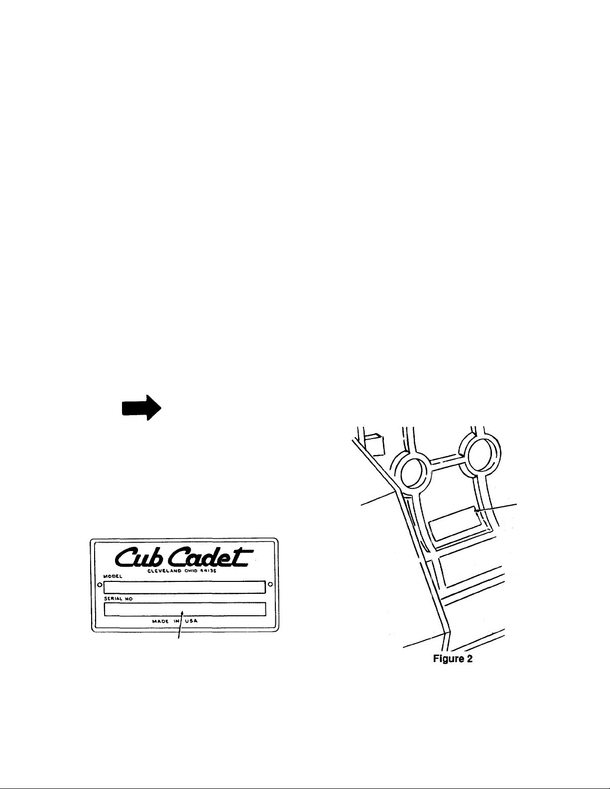
Chassis serial number plate is located near left rear
fender. (See Figure 1.)
CHASSIS SERIAL NUMBER
Figure 1
Engine serial number is located on the left hand, for
ward part of engine at engine rrx>unting plate. (See
Figure 2.)
ENGINE
SERIAL
NUMBER
MODEL.
DELIVERY DATE.
Page 8
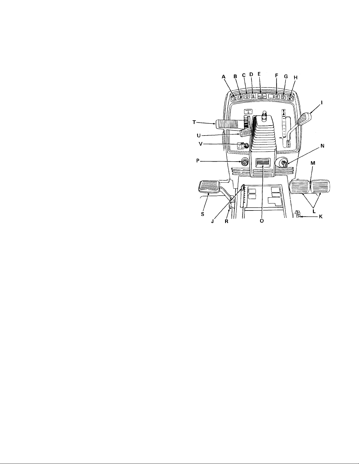
SECTION I. CONTROLS
Your Cub Cadet Tracxor has been safety engineered.
Thoroughly acquaint yourself with all the instruments
A. Low Oil Indicator
B. Low Fuel Indicator
C. Amp Indicator
D. Temp Indicator
E. Hour Meter
F. Reverse "R” Indicator
G. Disengage PTO Indicator
H. Depress Left Pedal Indicator
I. Speed Control Lever
J. Lift Height indicator
K. Cam Lock Knob
L. Turning Brake Pedals
M. Turning Brake Lock
N. Ignitlon/Light Switch
O. Tilt Wheel Release Lever
P. Choke Control
Q. Seat Adjustment Lever (Not Shown)
R. Single Pedal Brake Lock
S. Single Brake Pedal
T. Hydraulic Lift Control Lever
U. Throttle Control Lever
V. Front Power Take-Off (PTO) Control Switch
W. Fuse (Not Shown)
X. Safety Interlock Switches (Not Shown)
and controls before attempting to start or operate the
tractor.
Figure 3
A. LOW OIL INDICATOR
This indicator will illuminate when the oil level is low.
A
When "LOW OIL" indicator illuminates, stop
the tractor and check the oil level. Continu
ing to operate the tractor could result in
severe damage to the engine.
B. LOW FUEL INDICATOR
This indicator will illuminate when the fuel level in the
fuel tank is low.
C. AMP INDICATOR
This indicator will illuminate when a problem exists
with the charging system or the battery. If this indica
tor illuminates, stop the tractor and contact your
Cadet Dealer.
CAUTION
Cub
D. TEMP INDICATOR
This indicator will illuminate if the engine is overheat
ing.
CAUTION
A
When ’TEMP" indicator illuminates, immedi
ately stop the tractor and allow the engine to
cool. Then check the coolant level in the
radiator and examine the radiator screen for
accumulated debris.
E. HOUR METER
The hour meter indicates the actual hours of engine
operation. This enables the operator to determine
when lubrication, change of oil or periodic inspections
are necessary. It also provides a means of computing
cost of specific jobs. The hour meter operates when
ever the engine is running or the ignition key is in the
"ON" position.
Page 9
F. REVERSE ”R" INDICATOR
This indicator is illuminated when the tractor is in
reverse. The reverse "R" indicator must be off before
the tractor can be started.
G. DISENGAGE PTO INDICATOR
This indicator will illuminate if an attempt is made to
start the tractor with the PTO switch engaged. This
indicator must be off before the tractor can be started.
When starting the tractor, this indicator will briefly
flash.
H. DEPRESS LEFT PEDAL INDICATOR
This indicator will illuminate when an attempt is made
to start the tractor with the single brake pedal not fully
depressed.
I. SPEED CONTROL LEVER
NOTE
K. CAM LOCK KNOB
The cam lock knob is used to adjust the cam stop,
which will allow an attached implement to return to a
single preset height. (See Figure 5.)
With the implement at a desired height, release cam
stop by turning locking knob counterclockwise. Turn
cam stop until it contacts tang. Lock cam stop into this
position by turning cam knob clockwise.
Do not rest your foot on the single brake
pedal while driving the tractor as this would
cause the speed control lever to return to the
"N" position.
The lever is used to select any speed from a standstill
“N" position to eight miles per hour in the fonvard
direction and four miles per hour in the reverse direc
tion.
Moving the speed control lever forward provides
increased forward speed, and rrwving the lever rear
ward provides the reverse speeds. (See Figure 3.)
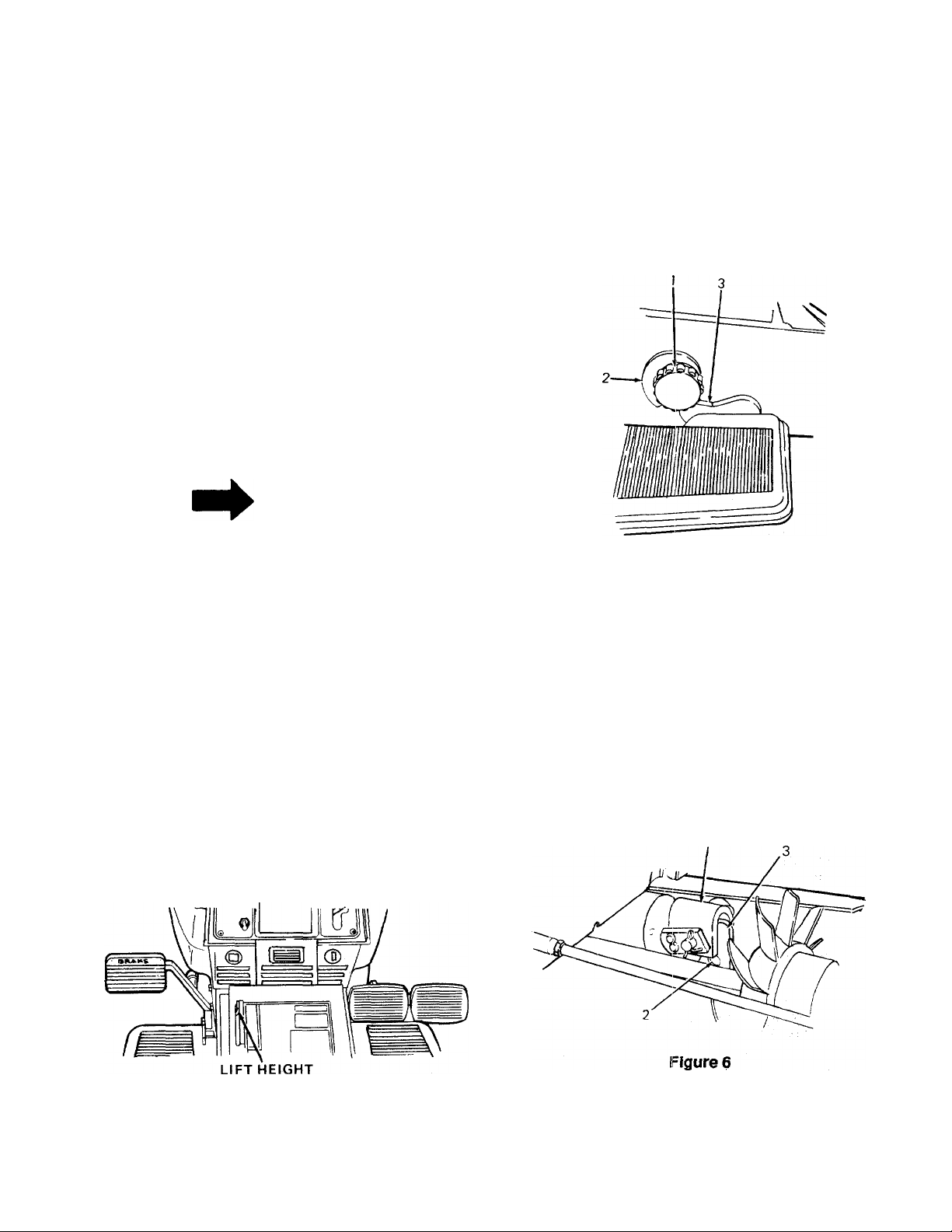
J. LIFT HEIGHT INDICATOR
The lift height indicator will indicate the height of deck
attachment when installed. (See Figure 4.)
Figure 5
1. Locking Knob
2. Cam Stop
3. Tang
Equipment is normally operated in a "Float" position
(implement free to move upward).
To operate equipment in a fixed "Locked" position,
where down pressure of the implement is required
(blade work), remove frame cover and install bolt, 1/2
X 1-1/8 inch (not furnished with tractor), between the
lift arm and lift bracket. (See Figure 6.)
INDICATOR
Figure 4
1. Lift Bracket
2. Hole for Bolt
3. Lift Arm
Page 10
L. TURNING BRAKE PEDALS
NOTE
CAUTION
A
Use the two turning brake pedals only at low
speeds to maintain control of the tractor
when using rear mounted equipment.
The two turning brake pedals are used for individual
braking of the rear wheels to aid in turning the tractor
in soft soii conditions. (See Figure 7.) Depress the
outside turning brake pedal to slow or stop the right
rear tractor wheei; depress the inside turning brake
pedal to slow or stop the left rear tractor wheel. The
tractor will turn in the direction of the wheel that is
slowed or stopped.
Turning brake pedais must be latched
together when operating the tractor in trans
port speeds.
The turning brake iock is located in the top edge of the
outside turning brake pedal (see Figure 7) and is used
to lock the two turning brake pedals together to pro
vide simultaneous braking to both rear wheels when
the turning brake pedals are depressed. To lock the
pedals together, pivot the lock and engage it in the slot
on the inside turning brake pedai. For individual brake
action, pivot the lock into the storage slot in the out
side turning brake pedai.
if the turning brake pedals are not locked together and
the single brake pedal is used, only the left rear tractor
wheel is slowed or stopped.
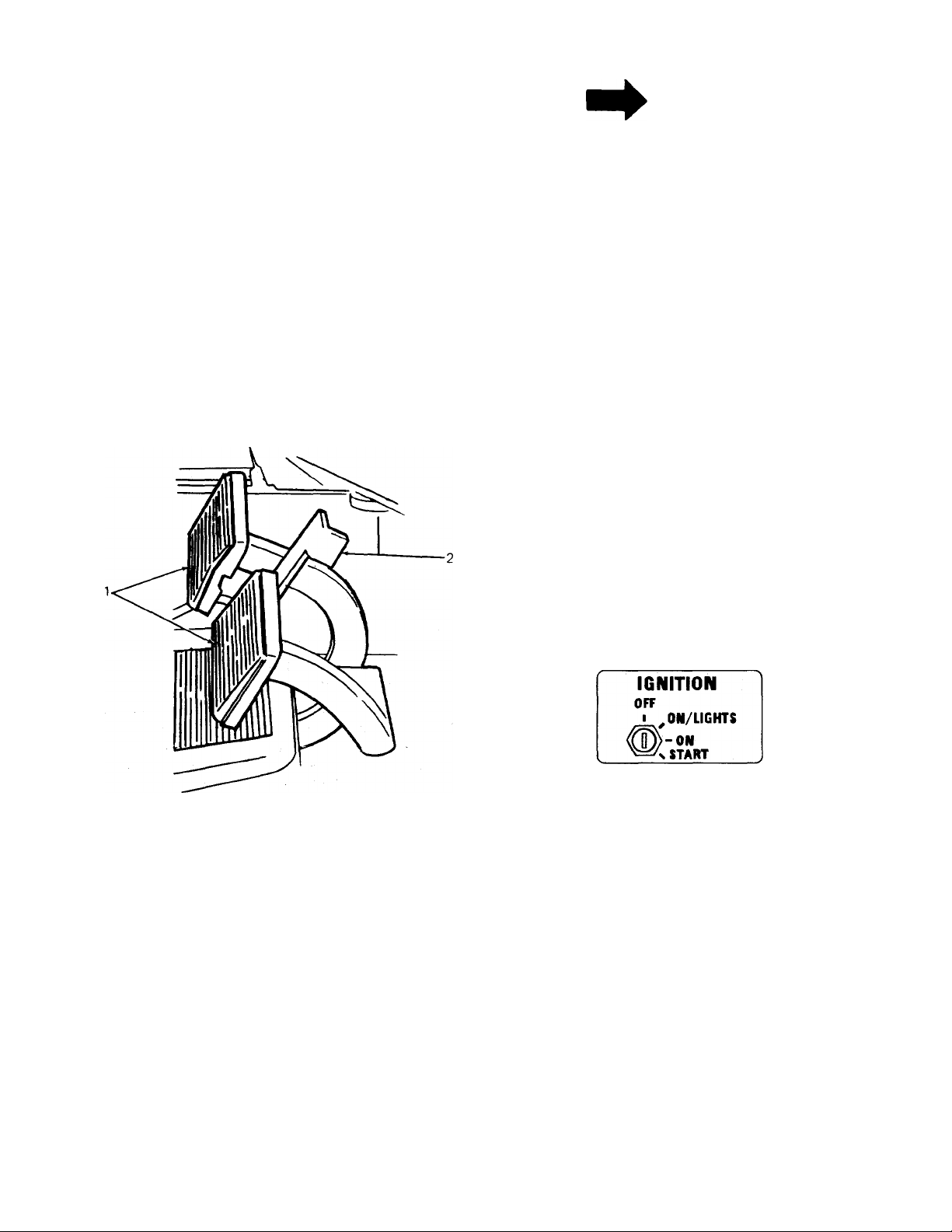
N. IGNITION/LIGHT SWITCH
WARNING
A
Remove the key from the tractor when the
tractor is not in use to prevent accidentai
starting and battery discharge.
Figure 7
1. Turning Brake Pedals
2. Turning Brake Lock
M. TURNING BRAKE LOCK
CAUTION
A
Turning brake pedals should not be used
when mowing lawns. The wheel being
braked may skid and cause iawn damage.
Turning brake pedals should be locked
together.
The combination lights and ignition switch is a fourposition switch. (See Figure 8.)
Figure 8
O. TILT WHEEL RELEASE LEVER
The tilt wheel release lever is used to adjust the steer
ing wheel forward away from the operator or rearward
towards the operator. Refer to ADJUSTING THE
STEERING WHEEL in Section 111.
P. CHOKE CONTROL
The choke control is operated manuaily. Pull knob out
to choke engine. Push knob in to open choke. (See
Figure 3.)
Q. SEAT ADJUSTMENT LEVER
The seat adjustment lever is used to move the seat
forward or rearward. Refer to ADJUSTING THE
SEAT in Section 111.
10
Page 11
R. SINGLE PEDAL BRAKE LOCK
T. HYDRAULIC LIFT CONTROL LEVER
A
The hydrostatic transmission will not hold
the tractor on a hill. In a short period of time
(depending on the steepness of the hill) the
oil will drain from the transmission and allow
the tractor to roll downhill. To avoid an
accident and/or possible injury, engage the
single pedal brake lock.
Always engage the single pedal brake lock when
dismounting the tractor. To lock the brake, the turning
brake pedals must be locked together to provide brak
ing to both rear wheels. Refer to TURNING BRAKE
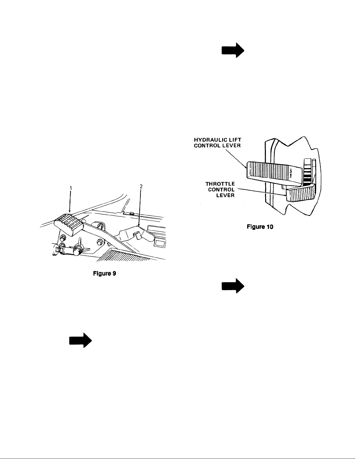
LOCK." Depress single brake pedal and place the sin
gle pedal brake lock in the engaged position. (See
Figure 9.) To disengage the lock, press down on the
pedal, lift the lock up and place it in the disengaged
position.
,WARNING
NOTE
The engine must be running in order to
operate the hydraulic lift.
The hydraulic lift control lever controls the raising and
lowering of equipment used with the tractor, if
installed. The control lever is spring loaded. To raise
the equipment, pull up on the lever. To lower the
equipment, push down on the lever. (See Figure 10.)
1. Single Brake Pedal
2. Single Pedal Brake Lock
S. SINGLE BRAKE PEDAL
NOTE
Do not rest your foot on the single brake
pedal while driving the tractor as this would
cause the speed control lever to return to the
"N" position.
The single brake pedal must be pressed all the way
down to activate the safety starting switch. When the
single brake pedal is in the depressed position it
automaticaily moves the speed control lever to the "N"
position. (See Figure 9.)
U. THROTTLE CONTROL LEVER
This lever controls the sipeed of the engine. When set
in a given position, it will maintain a uniform engine
speed. (See Figure 10.)
NOTE
When using power take-off operated equip
ment, best performance is achieved with the
throttle lever in the "FAST" position.
This symtrol shows slow ("IDLE") posi
tion.
This symbol shows fast position.
V. FRONT POWER TAKE-OFF (PTO) CONTROL
SWITCH
The power take-off (PTO) control switch, which is
located on the left side of the instrument panel,
operates an electric clutch. (See Figure 3.) This elec
tric clutch controls the engagement ("ON”) or disen
gagement ("OFF") of the front PTO.
11
Page 12
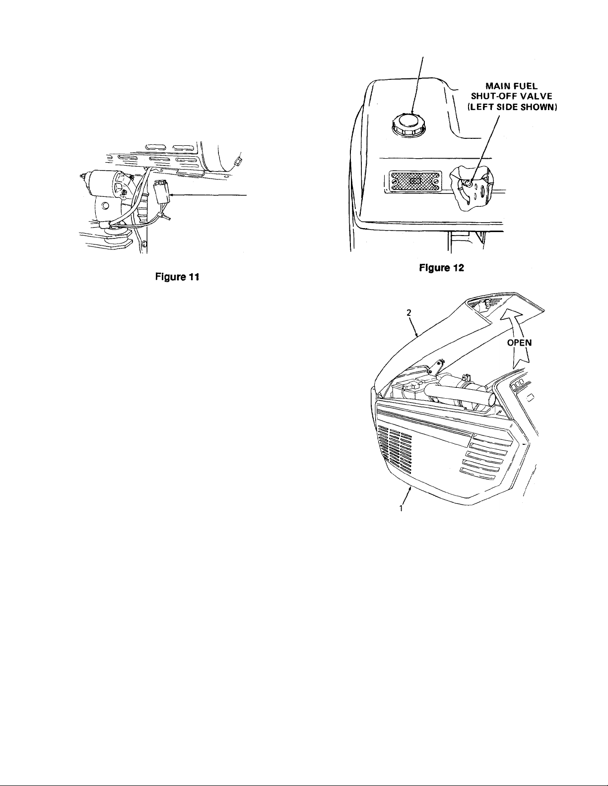
W. FUSE
A fuse is located under the hood on the right side of
the battery tray. It is installed to protect the tractor’s
electrical circuitry and components from damage
caused by excessive amperage overload. (See Fig
ure 11.) (Side panel removed for clarity.)
FUSE
X. SAFETY INTERLOCK SWITCHES
The safety interlock system prevents the engine from
cranking or starting unless the single brake pedal is
fully depressed, and the PTO switch is in the "OFF"
position.
FUEL TANK FILLER CAP
The safety interlock system will automatically shut off
the engine if the operator leaves the seat before
engaging the single pedal brake lock.
The safety interlock system will automatically disen
gage the PTO if the operator leaves the seat with the
PTO in the "RUN" position, or the unit is shifted into
reverse with the PTO in the "RUN" position. To reen
gage the PTO. place the speed control lever in neutral
("N"), move the PTO switch into the "OFF" position
and then engage the PTO while seated.
FUEL TANK
The fuel tank is located in the rear of the tractor. The
fuel tank filler cap is located on the left rear fender.
The main fuel shut-off valves are located on the bot
tom (left and right sides) of the tank. These valves
control the flow of fuel to the engine. To open the
valves turn the knobs counterclockwise until they stop.
To close the valves turn the knobs clockwise until they
are tight. (See Figure 12.)
HOOD AND SIDE PANELS
The tractor hood is arranged to swing up and forward
for easy access to the engine compartment. (See Fig
ure 13.) Whenever engine maintenance is required,
the side panels can be removed.
Figure 13
1. Side Panel (One On Each Side)
2. Hood
WARNING
A
To avoid burns from hot engine or muffler,
remove side panels only when engine is
cold.
To remove either right or left side panel, proceed as
follows:
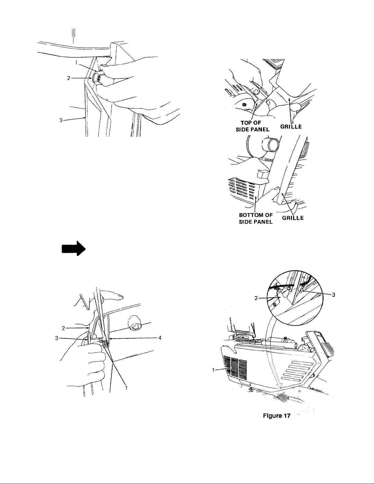
1. Engage the single pedal brake lock. Raise the
hood. Refer to Figure 14 and at top rear of side
panel remove wing nut and flat washer.
12
Page 13
NOTE: LEFT SIDE PANEL SHOWN
Figure 14
1. Wing Nut
2. Flat Washer
3. Side Panel
Loosen LEFT front side panel by applying pres
2.
sure to side of grille and gently pulling on side
panel until the snaps pop out of grille side flange.
(See Figure 15.)
3.
Loosen RIGHT front side panel by first popping
the top snap out of the grille side flange. Then
grasp front of panel below muffler and pull gently
to rerrx)ve bottom snap. (See Figure 16.)
RIGHT SIDE PANEL
NOTE
Be sure both top and bottom snaps have
popped out.
LEFT SIDE PANEL
Figure 15
1. Snap
2. Grille
3. Side Panel
4. Grille Side Flange
Figure 16
4. Locate the lock tab and dash panel lock in Figure
17.
1.
Side Panel
Lock Tab
2.
Dash Panel Lock
3.
13
Page 14
Remove LEFT or RIGHT side panel as follows:
5.
Unseat lock tab by gently pulling front of side
panel towards you. Then pull up and slide panel
forward to disengage dash panel lock. {See Fig
ure 18.)
NOTE: LEFT SIDE PANEL SHOWN
Figure 18
1. Lock Tab
2. Side Panel
3. Dash Panel Lock
SIDE
PANEL
NOTE: LEFT SIDE PANEL SHOWN
Figure 20
3. Grasp top center of panel as shown in Figure 21
and gently pull toward you in order to position
mounting hole over stud.
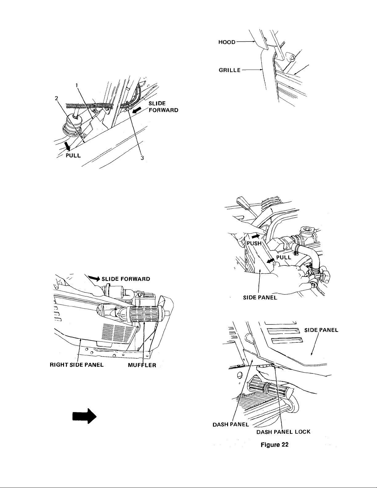
4. Gently pull tip of dash panel toward you and push
in and engage dash panel lock. (See Figure 22.)
5. Install flat washer and wing nut.
To install panels:
1. Position right side panel with front cut out area
placed behind the muffler as shown in Figure 19.
Slide fonward positioning panel on tractor and
secure two front snaps.
Figure 19
Position left side panel on tractor and secure two
front snaps.
Figure 21
NOTE
Make sure upper front corner of both side
panels are inside lip on grille as shown in
Figure 20.
14
Page 15

SECTION II. OPERATION
WARNING
A
RECEIVE INSTRUCTION - Read operator’s
manual. Learn to operate this machine
SAFELY. Don’t risk INJURY or DEATH.
1. Before starting engine or operation: Be
familiar with controls. Be in operator’s
positron with speed control lever in neu
tral, PTO turned off and single brake
pedal depressed.
2. Keep shields in place. Keep away from
rrroving parts.
3. NO RIDERS! Keep all people and pets
a safe distance away. Look before
backing up.
4. Don’t point mower discharge at people.
5. Avoid slopes. Tractors can be rolled
over.
6. Before leaving operator’s position: Shut
off PTO. Place speed control lever in
neutral. Engage single pedal brake
lock. Shut off engine. Remove ignition
key. Wait for all movement to stop
before servicing or cleaning.
7. Do not fill gasoline tank when engine is
running or while engine is hot. Tighten
cap securely.
8. Remove the side panels and clean any accumu
lated grass and debris.
9. Clean the radiator screen.
10. Check the radiator fluid level.
11. Make certain that the backside of the grille insert
is clean and unobstructed. Push down on the top
of the grille insert and pull fonward as shown in
Figure 23. Lift the grille insert up removing the
tabs from the bottom of the grille housing.
Remove by hand any accumulated grass and
debris.
12. Refer to various sections of the Owner’s Manual
for additional information.
BEFORE OPERATING YOUR TRACTOR
1. Refer to "MAINTENANCE" and study this
manual carefully. It has been prepared to help
you operate and maintain your tractor with utmost
efficiency.
2. Familiarize yourself with the operation of all the
instruments and controls.
3. Fill the tank with either lead-free, low-lead or reg
ular gasoline. Make sure before you fill the tank
that the gasoline is clean and fresh.
4. Check the engine and transmission oil levels.
5. Clean the air cleaner element if necessary.
6. Check the tire inflation pressures.
7. Adjust the seat and steering wheel for operator’s
maximum comfort, visibility and complete control
of the tractor.
STARTING THE ENGINE
A
Do not operate tractor if the interlock system
is malfunctioning because it is a safety
device designed for protection.
A
Operator must be seated before starting the
tractor.
15
Figure 23
WARNING
WARNING
Page 16

NOTE
This tractor is equipped with a safety inter
lock system for the protection of the opera
tor.
The safety interlock system prevents the
engine from cranking or starling unless the
single brake pedal is fully depressed and the
PTO engagement switch is in the "OFF"
position.
The safety interlock system will automati
cally shut off the engine if the operator
leaves the seat before engaging the single
pedal brake lock.
NOTE
The safety interlock system will automati
cally disengage the PTO if the operator
leaves the seat with the PTO in the "RUN"
position, or the unit is shifted into reverse
with the PTO in the "RUN" position. To
reengage the PTO, place the speed control
lever in neutral ("N"), move the PTO switch
into the "OFF" position and then engage the
PTO while seated.
1. Operator must be seated.
8. After the engine starts, slowly release the single
brake pedal and gradually push the choke control
knob all the way in. Do not use the choke to
enrich the fuel mixture, except as necessary to
start the engine.
STOPPING THE ENGINE
CAUTION
A
Remove the key to prevent accidental start
ing and battery discharge if equipment is left
unattended.
Move the throttle lever to the "SLOW" position and
allow the engine to idle for a short time before stop
ping. Then turn the key to the "OFF" position.
Remove key from ignition switch.
COLD WEATHER STARTING
A
During operation do not run the engine in
confined area such as storage building any
longer than is necessary. Immediately move
the tractor outside into the air.
WARNING
2. Pull choke control knob to full choke position.
Less choking may be necessary due to variations
in temperature, grade of fuel, etc. Little or no
choking will be needed when the engine is warm.
3. Place the throttle midway between the "SLOW"
and "FAST" positions.
4. Place the PTO switch in the "OFF" position.
5. Place the speed control lever in neutral ("N").
6. Fully depress the single brake pedal.
NOTE
The speed control lever will return to neutral
when the single brake pedal is pressed all
the way down, and the linkage is properly
adjusted.
7. Turn the ignition key clockwise to the "START"
position and release it as soon as the engine
starts; however do not operate the starter for
more than 10 seconds at any one time. If the
engine does not start within this time, turn the key
"OFF" and wait a few minutes, then try again.
A
Operator must be seated before starting the
tractor.
WARNING
NOTE
In cold weather the starting motor may
disengage prematurely. This is caused by
the engine firing once but failing to continue
running. If this happens several times, the
engine will be flooded and it will be neces
sary to leave the throttle in the "SLOW" posi
tion but push the choke in all the way; then
turn the ignition key to the "START" position
and slowly pull the choke out to the position
which will cause the engine to start and con
tinue running. If the engine falters after put
ting tractor into motion, pull the choke out
part way until the engine runs smoothly, then
gradually push the choke back in as the
engine warms.
Engine starting is possible in cold weather providing
the correct weight of engine oil is used, the battery is
16
Page 17

fully charged and the proper starting procedure is fol
lowed. The best procedure for starting at tempera
tures near or below freezing are as follows:
1. Operator must be seated.
2. Pull the choke all the way out into the full choke
position.
3. Move the throttle lever midway between the
"SLOW" and "FAST" positions.
NOTE
When using power take-off operated equip
ment, best performance is achieved with the
throttle lever in the "FAST" position.
NOTE
4. Place the PTO switch in the "OFF" position.
5. Place the speed control lever in neutral ("N").
6. Fully depress the single brake pedal.
7. Move the key switch into the "START" position
and hold until the engine starts; however, do not
operate the starter for more than 10 seconds at
any one time. As soon as the engine starts,
slowly push the choke in part way.
DRIVING THE TRACTOR
A
When the engine is off, the tractor will
become very difficult to steer. This is
because the engine must be on for the
power steering to operate. Do not turn off
engine until tractor comes to a complete
stop or damage to equipment or injury to
persons might occur.
WARNING
CAUTION
A
Avoid sudden starts, excessive speed and
sudden stops.
A
Do not leave the seat of the tractor without
depressing the single brake pedal and
engaging the single pedal brake lock. If
leaving the tractor unattended, also turn the
ignition key off and remove the key.
CAUTION
Unless turning brake pedals are needed for
control in turning the tractor, they should be
locked together at all times to provide simul
taneous braking to both rear wheels.
1.
Depress the single brake pedal, release the sin
gle pedal brake lock and let the pedal up. Move
the throttle lever to the position where the engine
operates best for the load to be handled.
2.
Start the tractor in motion by moving the speed
control lever slowly forward or rearward to
desired speed.
DRIVING ON SLOPES
(Refer to "SLOPE GAUGE" on page 43 in order to
help determine slopes where you may not operate
safely.)
A
Do not mow on inclines with a slope in
excess of 15 degrees (a rise of approxi
mately 2-1/2 feet every 10 feet). A tractor
could overturn and cause serious injury.
A
Operate tractor up and down slopes, never
across slopes.
A
Always drive up or down the face of a slope.
Do not drive so that the tractor may tip over
sideways.
WARNINGj
WARNING
CAUTION
NOTE
Hydraulic power for the power steering will
take priority over installed hydraulically
driven accessories.
Before operating the tractor on any slope, walk the
slope to look for possible hazards such as rocks,
mounds, ruts, stumps or other surface irregularities
which could cause an upset.
17
Page 18

Back the tractor with implement up the steepest por
tion of each slope you intend to work. If the tractor
cannot negotiate the slope in reverse, the slope is too
steep to be worked.
Avoid turns when driving on a slope. If a turn must be
made, turn down the slope. Turning up a slope
greatly increases the chance of a roll over.
Avoid stopping when driving up a slope. If it is neces
sary to stop while driving up a slope, start up smoothly
and carefully to reduce the possibility of flipping the
tractor over backward.
STOPPING THE TRACTOR
A
Always engage single pedal brake lock,
lower equipment and shut off engine before
dismounting. Never try to start engine from
ground.
Fully depress the single brake pedal. When the trac
tor has stopped, make sure the speed control lever is
in the neutral ("N") position. Before dismounting
always disengage the PTO switch, engage the single
pedal brake lock and turn the ignition "OFF".
CAUTION
OPERATING THE FRONT POWER TAKE-OFF
(PTO) CLUTCH
NOTE
Be certain to follow break-in instructions
listed below.
1. Move the throttle lever back to the medium or
"SLOW" position.
2. Flip the toggle switch to the "RUN" (C) position.
(See Figure 25.)
3. Advance throttle to operating speed (full speed).
4. The operator must remain in tractor seat at all
times. If operator should leave tractor seat
without turning off the power take-off switch, the
PTO will automatically disengage.
5. PTO switch must be in the "OFF" (A) position
when shifting the tractor into reverse or the PTO
will shut off automatically. To reengage the PTO,
shift unit into neutral. Move PTO switch to "OFF"
(A) position. Then pull knob out and lift up to
"STARP' (B) position and release.
The turning brake pedals must be latched together to
provide braking to both rear wheels. Latch turning
brake pedals together before locking single brake
pedal.
DRAWBAR
Drawbar equipment must be hitched to the tractor only
at the hitch hole in the drawbar. (See Figure 24.)
Figure 25
FRONT PTO CLUTCH BREAK-IN PROCEDURE
To break-in the components and increase the life of
the clutch assembly, proceed as follows.
1. Attach mowing deck, snow thrower, etc. to the
tractor.
2. Adjust the belt tension as recommended in
attachment owner’s manual.
3. Engage and disengage the PTO ten to fifteen
times without any load (not cutting grass, not
blowing snow, etc.).
18
Page 19

SECTION III. ADJUSTMENTS
ADJUSTING THE SEAT
A
Do not adjust the seat when the tractor is
moving. Adjusting the seat while the tractor
is moving could cause the operator to lose
control of the tractor.
Before starting the tractor, adjust the seat forward or
rearward to the most comfortable driving position. To
reposition the seat, move the seat adjustment lever
(Figure 26) to the left and slide the seat forward or
rearward. Release the adjustment lever when seat is
comfortably positioned. Gently rock the seat forward
and rearward once to be sure seat is locked in place.
.WARNING
Before starting the tractor, adjust the steering wheel
fonward or rearward to the most comfortable position.
To position the steering wheel, push the tilt wheel
release lever down, as shown in Figure 27, and move
the steering wheel fonvard or reanward. Release the
lever when the steering wheel is comfortably posi
tioned. Gently push the steering wheel forward or
reanward once to be sure wheel is locked in place.
Make sure tilt wheel release lever is all the way up as
shown in Figure 28.
ADJUSTING THE STEERING WHEEL
A
Do not adjust the steering wheel when the
tractor is moving. Adjusting the steering
wheel while the tractor is moving could
cause the operator to lose control of the
tractor.
WARNING
Figure 27
19
Page 20

ADJUSTING THE POWER TAKE-OFF CLUTCH
WARNING
A
To avoid possible injury, move speed control
lever into neutral, engage the single pedal
brake lock and turn the ignition "OFF" before
working on the machine.
Brake adjustment check:
1. To check brake adjustment, place a 1 inch thick
wood block between the single brake pedal and
the brake lock tab (see Figure 30).
2. With the 1 inch thick wood block installed, the
brake disc pads should be applying a light
amount of friction against the brake disc rotor. If
they are not, the brakes need adjustment (see
Figure 31).
A
The clutch may be hot. Allow the engine
and clutch to cool before adjusting the
clutch.
The clutch is factory adjusted and should not require
further adjustment under normal operating conditions.
However, if the clutch fails to operate properly, check
as follows:
Using a feeler gauge, check the air gap. (See Figure
29.) Insert feeler gauge into one of three access slots
located around the outside of the brake plate. The air
gap should be .017 inch. Adjust the self-locking nuts
to obtain the proper clearance. Repeat the operation
in all three access slots.
WARNING
Figure 30
1. Single Brake Pedal
2. Brake Lock Tab
3. 11nch Thick Wood Block
Figure 29
1. Access Slots (120° apart In 3 locations)
2. Brake Plate
3. Self-Locking Nuts
BRAKE ADJUSTMENT
During normal operation on this machine, the brakes
are subject to wear and will require periodic examina
tion and adjustment.
Brake adjustment:
(See Figure 31)
1. Latch turning brake pedals together.
2. Place a 1 inch thick wood block between the sin
gle brake pedal and the brake lock tab (see Fig
ure 30).
3. Remove cotter pins and washers from rear end of
both brake rods and loosen jam nuts from clev
ises.
4. Block the front wheels and raise the rear wheels.
5. Adjust each brake rod in turn by:
A. To tighten the brakes, shorten the length of
the brake rod by turning it into the clevis.
B. To loosen the brakes, make the brake rod
longer by turning it away from the clevis.
6. Adjust the brake rods until the disc pads apply a
light amount of friction against the rotor.
20
Page 21

1. Cotter Pin and Washer (Both Sides)
2. Brake Rod (Both Sides)
3. Jam Nut (Both Sides)
4. Clevis (Both Sides)
5. Disc Pads (Both Sides)
6. Rotor (Both Sides)
7. Clearance Between Disc Pads and Rotor
(Both Sides)
8. Turning Brake Pedal Arms
9. Brake Assembly Mounting Bolts
7. Reinstall cotter pins, washers and tighten jam
nuts.
8. Recheck brake adjustment. If the adjustment is
correct, remove wood block and lower tractor.
9. With the wood block removed, the brake disc
pads must not rub against the brake rotor.
WHEEL ALIGNMENT
The front wheels should toe-in approximately 1/8 inch.
Measure the distances A and B on the front wheels.
(See Figure 32.)
NOTE
Dimension B should be approximately 1/8
inch less than dimension A.
Figure 32
For adjustments on toe-in, see your authorized Cub
Cac/ef dealer.
21
Page 22

FRONT WHEEL ADJUSTMENTS
Check the front wheels to ensure that the turning
radius of the unit is equal in both directions. Turn the
wheels all the way to the left. Measure the angle of
the wheel to the frame. Turn the wheel all the way to
the right and repeat the measurement. The angles
shall be equal.
3. Tighten jam nut.
4. Repeat the above steps for the other pivot bar
adjustment boit.
CARBURETOR ADJUSTMENTS
NOTE
Power steering components are under
hydraulic pressure. If not properly adjusted,
serious damage may occur to steering com
ponents.
For adjustments on front wheels, see your authorized
Cub Cacfef dealer.
PIVOT BAR ADJUSTMENT BOLTS
CAUTION
A
The tractor must be checked every 50 hours
of tractor operation for play between the
front axle and the pivot bar adjustment bolts.
The adjustment bolt heads must fit against
the front axle. If play is discovered, the pivot
bar adjustment bolts must be adjusted.
If play is discovered between the front axle and the
pivot bar adjustment bolt heads, adjust both bolts as
follows: (See Figure 33.)
1. Loosen jam nut 3 to 4 turns or as required.
2. Turn pivot bar adjustment bolt counterclockwise
until it hits against the front axle.
A
If any adjustments are made to the engine
while the engine is running (e.g., carbure
tor), disengage all clutches and blades.
Keep clear of all moving parts and be careful
of heated surfaces and muffler.
A
To avoid injury or an accident, engage single
pedal brake lock, place speed control lever
in neutral and make sure equipment is
disengaged before starting engine to make
carburetor adjustments.
A
Carbon monoxide fumes can be fatal! Do
not make any adjustments to the carburetor
in a confined area such as a storage build
ing. Move the tractor outside into the air.
WARNING
WARNING
WARNING
NOTE
In this manual the tractor covered is
equipped with a fixed jet carburetor.
Figure 33
1. Jam Nut
2. Pivot Bar Adjustment Boits
3. Front Axie
22
Page 23

The carburetor is adjusted at the factory and under
normal operating conditions it will not require readjust
ing. However, if the engine does not operate properly,
what may appear to be a faulty carburetor adjustment
is in many cases a clogged air filter. This possibility
should be ruled out before attempting to readjust car
buretor. Refer to "MAINTENANCE" section in this
manual.
To prevent possible damage to the carburetor pilot
screw and throttle stopper adjusting screw, be very
careful when carburetor adjustments are made.
Improper adjustment of the carburetor may result in
engine damage.
FUEL SYSTEM
CHECKING AND ADJUSTMENT
Adjusting Carburetor (Idling)
1. Warm up the engine at a medium speed for 20 to
30 minutes, and then stop the engine.
2.
Tighten the pilot screw of the carburetor com
pletely, and then loosen it by 1 to 1.5 turns. (See
Figure 34.)
Tension Adjustment
Loosen the two bolts holding the alternator, and adjust
until proper tension is obtained. Be sure to retighten
the nuts and bolts after adjustment. (See Figure 35.)
THROTTLE STOPPER
ADJUSTING SCREW
CAUTION
A
Do not tighten the pilot screw too much. The
taper may become stepped.
3.
Start the engine, set the throttle control lever to
the lowest speed position, and then adjust the
engine speed with the throttle stopper adjust
ing screw of the carburetor in such a way the
engine maintains a lowest speed. (Adjust the
engine to the lowest speed but fast enough to
keep it running.)
4.
Tighten or loosen the pilot screw to adjust the
engine to the highest speed. (The speed drops
when the screw is turned too much in either direc
tion.)
5.
Screw in the throttle stopper adjusting screw
with the screw tip touching the throttle valve, until
the speed reaches approximately 1200 r.p.m.
FAN BELT
Fan Belt Tension and Damage
An improperly adjusted fan belt can cause engine
overheating. Push on the fan belt at the middle with a
finger, and check that it deflects about 0.4 in. (10 mm)
[at a load of 22.1 lb. (10 kg)]. Also check the belt for
cracks or tears.
Figure 35
23
Page 24

SECTION iV. MAINTENANCE
ENGINE OIL
The engine crankcase is filled with ship-away oil. This
oil may be used for the first 35 hours of engine opera
tion at temperatures between 0° and 90°F. If tem
peratures are not within this range, drain the oil from
the oil filter and crankcase and replace with new oil as
specified in the "LUBRICATION TABLE."
To aid starting, the selection of crankcase lubricating
oils should be based on the lowest anticipated tem
peratures until the next drain period.
Cub Cadet Low Ash Engine Oil meeting API Service
Classification SF or SG is recommended. For max
imum engine life select API SF or SG oils with lowest
levels of barium, calcium or magnesium additives and
minimum ash content (approximately 0.5%). Lubri
cant suppliers will normally furnish this information on
their engine oils.
For oil change intervals of 100 hours the following oils
are recommended.
17°f and above ■
32°F to 77<^F —
32°F to 0°F —
Cub Cadet Low Ash Engine Oil
S.A.E. 30W or S.A.E. 10W-30
S.A.E. 20Wor S.A.E. 10W-30
S.A.E. 10Wor S.A.E. 10W-30
3.
If the oil level is low, remove the oil port fill plug,
and add new oil to the prescribed level.
Figure 36
For other approved oils refer to
TABLE."
ENGINE OIL
Checking Oil Level and Adding Engine Oil
(See Figures 36 and 37.)
'LUBRICATION
CAUTION
A
Do not operate the engine with the oil level
nearing the iower mark because the oil may
deteriorate quickly. Keeping the oil level
near the upper mark is recommended (never
overfill).
1. Check the engine oil level before starting the
engine.
2. Remove the dipstick, wipe clean, reinsert it, take
it out again and check the oil level. Oil level
should be between the two marks at lower end of
dipstick.
OIL PORT FILLER PLUG
Figure 37
CHANGING ENGINE OIL
CAUTION
A
Stop the engine before changing oil.
1. Remove the drain plug at the bottom of the
engine, and drain all the old oil. Draining oil will
be easier and complete if done while the engine
is still warm.
2. Replace drain plug and add new engine oil up to
the upper mark of the dipstick.
3. Engine should be started, run briefly, stopped and
oil level rechecked.
24
Page 25

REPLACING THE OIL FILTER CARTRIDGE
(See Figure 38)
The oil filter can be obtained through your Cub Cadet
dealer under Part Number KB-70000-15241.
CAUTION
A
Stop the engine before replacing the oil filter
cartridge.
Wipe off any excess oil after installing filter.
1. Replace the oil filter cartridge after the first 35
hours. Thereafter, change the oil filter with every
other engine oil change.
2. Remove the oil filter cartridge with a filter wrench.
OIL CHANGE INTERVALS
OIL
Initial Change
Normal Change
ENGINE OIL LEVEL CHECKS
1. Engine oil level should be checked before starting
the unit every time.
2. Dipstick markings indicate upper and lower limits
at a cold oil condition.
3. Never overfill engine oil.
35 hours
100 hours
OIL FILTER
35 hours
200 hours
3. Apply a film of oil to the gasket of the new car
tridge.
Figure 38
4. Screw in the cartridge by hand. When the gasket
comes into contact with the seal surface, tighten
the cartridge an additional 1/2 turn by hand.
5. After the cartridge has been replaced, the engine
oil level drops. Thus, run the engine for a while
and check for oil leaks around the seal. Recheck
the engine oil level. Add oil if necessary.
DO NOT USE: Synthetic oil, non-detergent oil or
other non-recommended oils.
DO NOT MIX different brands of oil.
ENGINE OIL CAPACITY—98.4 oz. (approximately
6.2 pints) including oil in oil filter.
RADIATOR AND COOLANT
WARNING
A
It is dangerous to remove the radiator pres
sure cap when the system is hot. Allow the
system to cool and remove the cap cau
tiously.
CAUTION
A
1. Make it a rule to check the coolant level
before every operation.
2. Never use dirty or salt water as coolant.
3. Be sure to tighten the radiator pressure
cap securely after checking coolant.
4. When coolant is added, coolant level
may drop the first time the engine is
started. After operating tractor briefly,
allow system to cool and recheck
coolant level.
5. To drain coolant, always open both
coolant cocks located at the crankcase
side and at the lower part of the radia
tor; simultaneously open the radiator
cap as well. With the cap tightly closed,
a complete drain of coolant is impossi
ble.
25
Page 26

Checking Level, Adding and Changing Coolant
(See Figure 39)
NOTE
NOTE
Water and antifreeze must be mixed prior to
filling radiator.
The radiator screen must be removed before
the radiator pressure cap can be removed.
Refer to RADIATOR SCREEN CARE.
1. Remove the radiator pressure cap, and check to
see if water reaches the supply port.
2. In the event of insufficient coolant, fill the radiator
with proper coolant. In addition, check two drain
cocks at the lower part of the radiator and the
side of the crankcase to see if they are securely
closed.
Tractors shipped in the United States and Canada
have the cooling systems filled with antifreeze solu
tion.
WATER LEVEL FULL
RADIATOR SCREEN CARE
WARNING
A'
Do not service the radiator screen when the
engine is running or hot.
CAUTION
A
Do not operate tractor without radiator
screen in place.
NOTE
Radiator screen must be cleaned more fre
quently in dusty and high grass cutting con
ditions. This is to prevent overheating of the
engine.
To remove the radiator screen, lift the hood and
remove the wing nut and washer from the upper rear
corner of the right side panel. Pull outward on the
side panel slightly, grasp the top of the screen and pull
it up and out. Flush off any accumulated grass or
debris. Reinsert screen after cleaning. (See Figure
40.)
Hot Weather Operation
We recommend the use of water with the addition of
cooling system conditioner. The boiling point of
ethylene glycol solution is higher than that of water,
but the ability to transfer heat is less. As a result, the
engine will run cooler with conditioned water.
Other than Hot Weather Operation
We recommend the use of antifreeze with a mixture
ratio to protect the coolant to the lowest anticipated
temperature or a minimum of 33 percent antifreeze for
rust and corrosion protection.
RADIATOR COOLANT MIXTURE
Total coolant -1 U.S. gallon (8 pints).
Coolant consists of 50-50 mixture
quarts antifreeze (ethylene glycol).
2 quarts water, 2
CAUTION
A
Radiator screen must be cleaned before
each use and kept free of debris.
Figure 40
26
Page 27

AIR CLEANER
(See Figures 41,42 and 43)
1. The element of the air cleaner on this engine is
dry type. Never apply oil to it.
AIR CLEANER COVER
4. To ciean the element, use clean dry compressed
air on the inside of the element. Maintain reason
able distance between the nozzle and the filter.
Air pressure at the nozzle must not exceed 100
psi (7 kgf/cm, 690 kpa).
2.
Remove and clean out the dust cup every day if
the work surroundings are dusty. Never allow
dust cup to become half full with dust. (See Fig
ure 42.)
AIR CLEANER COVER
5. When carbon or oil adheres to the element, soak
the element in a mixture of 2 oz. detergent dis
solved in 1 gallon of water for 15 minutes, then
wash it several times in water, rinse with clean
water and air dry completely. After element is
fully dried, inspect inside of the element with a
light and check if it is damaged. (Refer to the
instruction on the label attached to the element.)
6. Replace the element every year or after every six
cleanings.
IMPORTANT
Install the dust cup with the keyed edge
towards the left side of tractor. If the dust
cup is mounted incorrectly, dust or dirt does
not collect in the cup, and dust will cause
severe engine damage.
HYDROSTATIC DRIVE HYDRAULIC FLUID FILTER
Figure 42
3. Avoid removing the element except when clean
ing. To remove the element, first remove wing
nut by turning counterclockwise. (See Figure 43.)
NOTE
Clean the outside area before removing the
filter to keep dirt from getting into the
transmission case. If a mower is mounted
on the tractor, the mower must be lowered
to facilitate removal of the filter.
27
Page 28

Remove the throw-away-can-type filter and replace
with a new filter after the first 10 and 50 hours of
operation, and every 100 hours of operation
thereafter. The filters can be obtained through your
Cub Cadet Dealer under part number 723-3014.
To remove the filter, turn the filter counterclockwise
using an automotive-type filter wrench.
Before installing the new filter, apply a coating of oil on
the filter gasket. Thread the new filter on by hand until
tight enough to seat the gasket. Loosen the filter.
Then turn it until the gasket contacts the base.
Tighten the filter an additional 1/2 turn. Start engine
and allow it to run for a few minutes. Shut engine off
and check for leaks; check oil level in transmission
case.
SPARK PLUGS
A
To avoid possible injury, be sure engine is
off and cool before making any adjustment
or repairs.
WARNING
NOTE
Remove all dirt from around the spark plugs
before removing.
To remove spark plugs, always use a spark plug
wrench. Check gap after every 200 hours of opera
tion.
Replace a defective plug with a new plug. Set gap at
0.043 inch. (See Figure 44.) Tighten plug to 14.5-
18.1 ft-lbs. See your authorized dealer for the correct
replacement plug.
The engine is equipped with an inline fuel filter. Visu
ally inspect the filter periodically. Replace yearly or
when dirty. (See Figure 45.)
LIGHTS
Refer to "SPECIFICATIONS" when replacement of
head lamp bulb or taillight bulb is necessary.
WARNING
A
Do not change head lamp bulbs when hot or
when engine is hot.
CAUTION
A
Do not touch glass portion ot head lamp
bulb. Touching glass portion will reduce life
of head lamp bulb.
NOTE
Prior removal of battery will ease removal
and replacement of head lamp bulbs.
1. Spark Plug
FUEL FILTER
A
Do not replace fuel filter when engine is hot.
WARNING
To replace a head lamp bulb, refer to Figure 46 and
remove the socket from the grille by rotating socket
1/4 turn. Pull old bulb assembly from socket and
insert new bulb assembly. Place socket into grille and
turn to lock in place.
28
Page 29

To replace a taillight bulb, remove socket from the
back of the taillight by rotating socket 1/4 turn.
Remove old bulb from socket and install new bulb.
Replace socket into taillight and turn to lock in place.
FUSE
Always use the same capacity fuse for replacement.
Refer to "SPECIFICATIONS." If electrical system
malfunctions, check the fuse.
To replace a fuse, pull the old fuse from the fuse
housing and install a new fuse. (Refer to Figure 11.)
BATTERY INFORMATION
WARNING
A
Battery acid must be handled with great care as
A.
contact with it can burn and blister the skin. It is
also advisable to wear protective clothing (gog
gles, rubber gloves and apron) when working with
it.*
Should battery acid accidentally splatter into the
B.
eyes or onto the face, rinse the affected area
immediately with clean cold water. If there is any
further discomfort, seek prompt medical attention.
If acid spills on clothing, first dilute it with clean
C.
water, then neutralize with a solution of
ammonia/water or baking soda/water.
Since battery acid is corrosive, do not pour it into
D.
any sink or drain. Before discarding empty elec
trolyte containers, rinse them with a neutralizing
solution.
NEVER connect or disconnect charger clips to
E.
battery while charger is turned on as it can cause
sparks.
Keep all lighted materials (cigarettes, matches,
F.
lighters) away from the battery as the hydrogen
gas generated during charging can be combusti
ble.
As a further precaution, only charge the battery in
a well-ventilated area.
MAINTENANCE OF BATTERY
1. Check electrolyte level periodically (at least every
two weeks). Keep the level to the split rings. Use
only distilled water or a good quality drinking
water. Never add acid or any other chemicals to
the battery after initial activation.
2. The battery should be checked with a hydrometer
after every 25 hours of operation. If the specific
gravity is less than 1.225, the battery should be
recharged. Maximum charge rate 5 amps.
3. Coat the terminals and exposed wire with a thin
coat of grease or petroleum jelly for longer serv
ice and protection against corrosion.
4. The battery should be kept clean. Any deposits
of acid should be neutralized with baking soda
and water. Be careful not to get this solution in
the cells.
5. Avoid tipping the battery. Even a "sealed" battery
will leak electrolyte when tipped.
STORAGE OF THE BATTERY
When storing battery for extended periods,
1,
disconnect battery cables. Removing battery
from unit is recommended.
Keep the exterior of the battery clean, especially
2.
the top. A dirty battery must be stored with a full
charge. A dirty battery will discharge itself.
Check the battery with a hydrometer. The battery
3.
must be stored with a full charge. A discharged
battery will freeze.
Specific Gravity
1.265
1.250
1.200
1.150
1.100
Freezing Point
-71 °F
-62° F
-16°F
5°F
16°F
*Always shield eyes and protect skin and
clothing when working near batteries.
A DANGER
BATTERIES CONTAIN SULFURIC ACID
AND MAY CONTAIN EXPLOSIVE GASES
(when electrolyte has been added).
KEEP BATTERIES OUT OF THE REACH
OF CHILDREN.
29
NOTE
All batteries discharge during storage.
Recharge battery whenever the specific gravity is
4.
less than 1.225, before returning to service or
every two months, whichever comes first.
Page 30

COMMON CAUSES FOR BATTERY FAILURE
Overcharging
1.
Undercharging
2.
Lack of water
3.
Loose hold downs and/or corroded connections
4.
5.
Excessive loads
Battery electrolyte substitutes
6.
7.
Freezing of electrolyte
NOTE
1. Attach the first jumper cable from the positive ter
minal of the good battery to the positive terminal
of the dead battery.
2. Attach the second jumper cable from the negative
terminal of the good battery to the FRAME OF
THE UNIT WITH THE DEAD BATTERY.
TIRES
Keep the pneumatic tires properly inflated. Over
inflation will cause operator discomfort. Underinflation
will cause short tire life.
These failures do not constitute warranty.
BATTERY REMOVAL OR INSTALLATION
WARNING
A
When removing the battery, follow this order
of disassembly to prevent your wrench from
shorting against the frame.
Battery removal:
1. Remove the Negative cable.
2. Remove the Positive cable.
Battery installation:
1. Attach the Positive cable.
2. Attach the Negative cable.
JUMP STARTING
WARNING
A
Failure to use this starting procedure could
cause sparking, and the gases in either bat
tery could explode.
Inflate the front and rear tires for normal or heavy load
operations as shown in the following table:
Tire Size
Front Tires
18x8.50-8
Rear Tires
26x12.00-12
Always see that the tire valve caps are in place and
tightened securely to prevent loss of air and protect
the valve core and stem.
Do not overload the tractor tires by mounting equip
ment on the tractor which exceeds the load capacity of
the size of the tires on the tractor.
MOUNTING TIRES ON THE RIM
After mounting a new or old tire on the rim, inflate it to
20 pounds pressure to seat the tire bead on the rim
flange. Then deflate the tire to the correct operating
pressure.
Pounds per Square Inch
12
12
NOTE
After the first 10 hours of operation, check
and retorque the wheel lug nuts (both sides)
to 35 ft-lbs. to make sure they have seated
properly.
30
Page 31

SECTION V. OFF-SEASON STORAGE
If the machine is to be inoperative for a period ionger
than 30 days, the following procedures are recom
mended;
WARNING
A
Never store engine with fuel In tank indoOrs
or In poorly ventilated enclosures, where fuel
fumes may reach an open flame, spark or
pilot light as on a furnace, water heater,
clothes dryer, etc.
1.
Remove all gasoline from fuel tank to prevent
gum deposits from forming on these parts and
causing possible malfunction of engine.
WARNING
A
Drain fuel into approved container outdoors,
away from open flame.
Fuel left in engine during warm weather
deteriorates and will cause serious starting
problems.
2.
Remove spark plugs and pour one (1) ounce of
engine oil through spark plug hole into cylinder.
Crank engine several times to distribute oil.
Replace spark plugs.
3.
Clean the engine and the entire tractor
thoroughly.
Run engine until engine starts to falter, then use
choke to continue engine operation until all fuel in
tank and carburetor is exhausted. Remove fuel
line at tank or carburetor and drain any remaining
gasoline from system.
4.
Lubricate all lubrication points.
5.
Follow battery storage instructions on page 29.
6.
Protect tires and seat from sunlight. Inflate tires
at regular intervals.
31
Page 32

SECTION VI. MOWING
MOWING
A
To avoid possible injury, do not allow any
one in the area opposite the discharge chute
while mowing. Although the area has been
supposedly cleared of foreign objects, small
objects may be discharged by the mower.
A
Never direct discharge of material toward
bystanders or allow anyone near the
machine while in operation.
For best results it is recommended that the first two
laps should be cut with the discharge thrown towards
the center. After the first two laps, reverse the direc
tion to throw the discharge to the outside for the bal
ance of cutting. This will give a better appearance to
the lawn.
WARNING
WARNING
Streaking may occur when attempting to mow heavy
weeds and tall grass. Under these conditions it may
be necessary to go back over the cut area a second
time to get a clean cut.
The following practices will help eliminate streaking:
1. Mow the area more often so the grass doesn’t get
too tall and heavy.
2. Operate the tractor at full throttle and lower for
ward speeds.
3. Keep the blades sharp and replace blades when
worn.
4. Follow the mowing procedure shown in Figure 47.
Do not cut the grass too short, as the mower will tend
to scalp the grass. Short grass invites weed growth
and yellows quickly in dry weather.
Mowing should be done with the engine at full throttle.
Do not mow at high ground speed.
During certain times of the year and under some con
ditions, the mower may leave streaks of uncut
material.
32
Page 33

OPTIONAL EQUIPMENT AND ACCESSORIES
When you purchased your tractor, you probably had it
completely equipped for your particular needs at the
time. However, later you may wish to obtain optional
equipment or accessories. These items and other
allied equipment can be purchased from, and installed
by, your authorized dealer.
The tractor is used for so many different types of work,
and because it is called on to operate under so many
different conditions, a variety of equipment is available
to adapt it to the requirements of the user. Refer to
equipment catalog.
33
Page 34

MAINTENANCE CHART
10 hours
Operation to
be performed
Clean grille insert,
(front & backside)
Check engine oil level
Fill fuel tank X
Change engine oil
Change engine oil
filter
Check transmission
oil level
Replace transmission
oil filter
Check battery electrolyte
level X
Grease front axle pivot
bolt
Lubricate steering knuckles
(2) & steering arm
Retorque rear wheel
lug bolts
Lubricate brake shaft X
Grease turning brake
pedal - RH
Service air cleaner, element
& dust cup
Lubricate speed control
linkage cam plates
Grease front wheel
bearings
Radiator coolant level
Radiator screen
Pivot bar adjusting bolt
Before
each use
X
X
Dust Cup
X
X
X
or once
a month
More often
under dirty
conditions
X
After 1 St
10 hours
X
X
X
After 1st
10 hours
X
35 hours
three times
a season
1 st time &
more often
under dirty
conditions
1st time
Thereafter
change with
every other
engine oil
change
50 hours
or twice
a season
After 1 St
50 hours
X
X
X
X or
when loose
100 hours
or
yearly
X X
Every 100
hours there
after
Air Cleaner
Element
More often
under dirty
conditions
X X
Before
storage
X
X
NOTE
Maintenance information for optionai equipment may be found in the manual which is included with the
specific piece of optional equipment.
34
Page 35

TROUBLE SHOOTING
Possible Cause Possible Remedy
HARD TO START
No gasoline in fuel tank or carburetor
Fuel line or carburetor clogged
Fuel filter plugged......................................................... Replace.
Water in gasoline.......................................................... Drain the fuel tank and carburetor. Use new fuel and dry
Choked improperly. Flooded engine
Defective ignition or loose wiring
Defective battery
Spark plug dirty or improper gap.................................. Clean, adjust the gap to 0.043-inch or replace the plug.
Engine incorrectly timed............................................... *
Spark plug dirty; wrong gap or wrong type
Poor or weak spark
Carburetor setting incorrect.......................................... Adjust. Refer to "ADJUSTMENTS."*
Poor grade fuel or water in fuel ................................... Drain and use a good grade of clean fuel.
Engine overheating
Engine valves at fault .................................................. *
Engine smokes............................................................. Adjust the carburetor.*
Oil level rises due to gasoline in crankcase
Air filter becomes oil and fuel soaked
Engine leaks oil ........................................................... Refer to "OPERATING IN COLD WEATHER."
Misfiring ....................................................................... Refer to "OPERATING IN COLD WEATHER."
Other engine problems................................................. *
........
................................................
.....................................................
......................................................
..........................
....................................
...........................
.................................
ENGINE OPERATES IRREGULARLY OR KNOCKS
..................
.................
.......................
Fill the tank with gasoline: open the fuel shut-off valves.
Check the fuel line, carburetor and fuel filter.
Clean the fuel line and carburetor with commercial car
buretor cleaner.
the spark plug.
Follow the starting instructions.
Check the wiring, spark plug or fuse.
Check and service. Refer to "BATTERY."
Clean, reset the gap or replace.
Check the spark plug and wiring.*
Refer to "MAINTENANCE."
Refer to "OPERATING IN COLD WEATHER."
Refer to "OPERATING IN COLD WEATHER."
*See your authorized dealer.
35
Page 36

TROUBLE SHOOTING
Possible Cause Possible Remedy
LACK OF POWER
Air cleaner clogged
Engine overload........................................................... Reduce the load.
Engine overheated ...................................................... Make sure radiator screen, side panels and grille insert
Poor fuel, too rich or too lean a mixture ...................... Refer to "ADJUSTMENTS."
Fuel tank air vent clogged............................................ Open the vent in the cap.
Incorrect timing or faulty ignition
Brake drags ................................................................. Adjust the brake. Refer to "ADJUSTMENTS."
Insufficient cool air, dirty radiator screen,
side panels or grille insert
Lean carburetor adjustment ........................................ Readjust. Refer to "ADJUSTMENTS."
Oil level incorrect
......................................................
..................................
ENGINE OVERHEATING
............................................
.........................................................
Service the air cleaner element. Refer to "MAINTE
NANCE."
are free of accumulated dirt and trash. Refer to
"MAINTENANCE."
Keep the air intake area, radiator screen, side panels
and grille insert clean; refer to "MAINTENANCE."
Engine oil level must not be over the "FULL" mark or
below the "LOW" mark. Refer to "MAINTENANCE."
*See your authorized dealer.
36
Page 37

LUBRICATION TABLE
Point of Lubrication
Engine crankcase
Hydro-drive unit
mounted on trans
mission case with
filter
Steering knuckles &
front axle pivot bolt
Front wheel
bearings
Alignment couplings
Check
Hours
Check
before
each
Check
before
each
Change
at
Hours
35
and
100
use
Add
needed
use
10 Use 251H EP grease or equivalent No.2 multi-purpose
35 Two or three strokes minimum of the lubricator using
at
as
Capacity
approx.
3.4 qts
including
oil in
oil filter
Approx.
14 pints
77°F and above
Cub Cadet
Low Ash
Engine Oil
SAE 30W or
SAE10W-30
Cub Cadet Hydraulic Transmission Fluid
NOTE: Cub Cadet hydraulic transmission fluid meets
IH B-6 specifications. If fluid is used that does not
meet these requirements,Cub Cadet will not be respon
sible for substandard performance. Failures due to use
of improper fluid are not covered by warranty. For
maximum protection, use Cub Cadet Hydraulic Trans
mission Fluid.
lithium grease and apply two or three strokes or suffi
cient grease to flush out old grease and dirt.
251H EP grease or eqivalent No. 2 multi-purpose
lithium grease.
251H EP grease or equivalent No. 2 multi-purpose
lithium grease.
AntlClp
lated Air Temperatijre
32°F to 77°F
Engine Oil
SAE 20W or
SAE10W-30
32°F to 0°F
Engine Oil
SAE 10W or
SAE10W-30
37
Page 38

LUBRICATION GUIDE
A
The life of any machine depends upon the care it is given. Proper lubrication is a very important part of
that care.
Be certain that all lubrication fittings are assembled in
place, using the lubrication illustrations as a guide.
Always lubricate the tractor thoroughly before taking it
to the field. Use a pressure lubricating gun.
Be sure all fittings are free from dirt and paint so the
lubricant is certain to enter the bearing.
Always force the lubricant through the full length of
each bearing until it emerges at the end, carrying with
it the worn lubricant and any dirt that may have
entered the bearing.
Miscellaneous working parts not provided with lubrica
tion fittings should be oiled daily with a good grade of
lubricating oil.
Lubricant is cheap. Use plenty of it. Worn parts can
be expensive to replace.
WARNING
Keep your supply of lubricating oil and grease stored
in clean containers, and covered to protect from dust
and dirt.
Keep the lubricating gun nozzle clean and wipe dirt
from grease fittings before lubricating.
The symbols in the illustration indicate the method of
application and the hourly intervals to apply the lubri
cant.
Use a pressure lubricating gun
and apply 251H EP grease {or
equivalent No. 2 multi-purpose
lithium grease) sufficient to
flush out the old grease and
dirt. Lubricate at hourly inter
vals indicated on symbols.
Dipstick, use to check engine
oil before each use.
38
Page 39

1. Engine filler cap and
dipstick
2. Steering knuckles (2)
(Both sides)
3. Transmission oil filter
LUBRICATION GUIDE
—Before Each Use
Check the oil (with the engine stopped) and add sufficient new oil to bring it to the
"FULL” mark on the dipstick. Do not overfill. Do not operate the engine if the oil
level is below the "LOW" mark on the dipstick.
—After Every 10 Hours of Operation
Use 251H EP grease or equivalent No. 2 multi-purpose lithium grease and apply
sufficient grease to flush out old grease and dirt.
NOTE: After the first 10 hours only, remove the transmission oil filter and replace
with a new filter. Refer to "MAINTENANCE." Change the transmission oil filter
after 50 hours and every 100 hours of operation thereafter.
4. Front axle pivot bolt
(Right side)
5. Transmission oil level
and fill tube
6. Turning brake pedalRH
7. Front wheel bearings
8. Engine oil drain plug
and oil filter
9. Transmission oil filter
Use 251H EP grease or equivalent No. 2 multi-purpose lithium grease and apply
sufficient grease to flush out old grease and dirt.
NOTE: It may be necessary to rotate the front axle to reach the grease fitting.
—After Every 30 Hours of Operation
Check the oil with the engine stopped. Keep the lubricant up to "FULL" mark on
dipstick.
NOTE: Transmission oil level and fill tube also services the following:
1. Hydrostatic transmission
2. Rear axle
3. Hydraulic lift system
4. Power steering
—After Every 35 Hours of Operation
Use 251H EP grease or equivalent No. 2 multi-purpose lithium grease and apply
sufficient grease to flush out old grease and dirt.
Two or three strokes minimum of the lubricator using 251H EP grease or
equivalent No. 2 multi-purpose lithium grease.
NOTE: After first 35 hours, while the engine oil is warm, remove the drain plug
and oil filter, and drain all of the oil from the crankcase and oil filter lines. Replace
the drain plug. Refer to "MAINTENANCE," "FILLING THE CRANKCASE" &
"OIL FILTER" for proper oil filling procedure. Refer to "LUBRICATION TABLE"
for the proper quantity and viscosity to use.
—After Every 50 Hours of Operation
NOTE: After the first 50 hours only, remove the transmission oil filter and replace
with a new filter. Refer to "MAINTENANCE." Change the transmission oil filter
every 100 hours of operation thereafter.
10. Transmission oil filter
11. Engine oil drain plug
Speed Control Linkage
12. Cam plates
—Every 100 Hours of Operation
Change the transmission oii filter and replace with a new filter.
"MAINTENANCE."
While the engine oil is warm, remove the drain piug and drain ail of the oil from
the crankcase. Replace the drain plug. Refer to "MAINTENANCE," and "FIL
LING THE CRANKCASE" for proper Oil filling procedure. Refer to "LUBRI
CATION TABLE" for the proper quantity and viscosity to use.
Once a year, apply a small amount of 251H EP grease or equivalent No. 2 multi
purpose lithium grease in the slots.
39
Refer to
Page 40

LUBRICATION GUIDE
Miscellaneous
Brake pedal shaft
Alignment couplings
Engine oil drain plug
and oil filter
Lubrication information for optional equipment may be found in the manual which is included with the
specific piece of optional equipment.
Lubricate the brake pedal shaft and linkage with eight or ten drops of engine oil.
Use 251H EP grease or equivalent No. 2 multi-purpose lithium grease.
—After Every 200 Hours of Operation
While the engine oil is warm, remove the drain plug and oil filter (5) and drain all
of the oil from the crankcase and oil filter lines. Replace the drain plug. Refer to
"MAINTENANCE,” "FILLING THE CRANKCASE" & "OIL FILTER" for proper
oil filling procedure. Refer to "LUBRICATION TABLE" for the proper quantity
and viscosity to use.
NOTE
40
Page 41

с
ш
2
о
>
о
Ç
а
гл
Page 42

SPECIFICATIONS
2182
CAPACiTIES
Fuel tank
Crankcase ..............................................................................
Transmission case with hydro-drive unit mounted..................
Cooling capacity
HYDROSTATIC DRIVE
Speed: Forward....................................................................... 0 to 7.5 mph
ENGINE
Make and model...................................................................... Kubota
(electric starting)...................................................................... 21 HP
Cylinders.................................................................................
Bore.........................................................................................
Stroke...................................................................................... 2.45 in.
Displacement (cubic inches) .................................................. 36.61 in.
Engine speed (governed)
Low speed............................................................................
High idle speed
Valve clearance (engine cold)
Intake................................................................................... 0.0057-0.0072 in.
Exhaust................................................................................ 0.0057-0.0072 in.
Ignition.....................................................................................
Spark plug gap (Cub CadetHo. KB-12581-67710)
ELECTRICAL SYSTEM
System voltage........................................................................
Battery.....................................................................................
Alternator.................................................................................
Fuse (auto type) .....................................................................
Head lamp bulb ......................................................................
Taillight....................................................................................
BRAKES ..................................................................................
TIRE SIZES
Front ...............................................................................
Rear
DIMENSIONS
Tread:
Front with 18 X 8.50-8 tires......................................................
Rear with 26 x 12.00-12 tires .................................................
Wheelbase
Length, overall.........................................................................
Width, overall...........................................................................
Height, overall (to top of steering wheel)
Ground clearance....................................................................
Turning radius.........................................................................
.................................................................................
6.2 pts. including oil in filter
1 gallon (2 quarts water, 2 quarts
anti-freeze) [ethylene glycol]
Reverse.......................................................................
(no load) ........................................................................... 3600 RPM
(full load)
........................................................................................
...........................................................................
.................
........
..............................................................................
................................
Specifications are subject to change without notice.
42
5 gals.
7 qts. approx.
0 to 4 mph
3
2.52 in.
1200 RPM
3350 RPM
Battery
0.043 in.
12 volt neg. ground
725-3174
15 amp
20 amp
725-3161
Lamp No. 194
Dual disc, external
18x8.50-8
26 X 12.00-12
33.0 in.
31.5 in.
51.6 in.
78.5 in.
43.5 in.
47.5 in.
7.6 in.
36.0 in.
Page 43

USE THIS SHEET AS A GUIDE TO DETERMINE SLOPES WHERE YOU MAY NOT OPERATE SAFELY.
SIGHT AND HOLD THIS LEVEL WITH A VERTICAL TREE
A POWER POLE
A CORNER OF A BUILDING
OR A FENCE POST
I
.........
...
ft
7^
o
o
■o
3;
w
V)
S’
o
(D
CO
(j3
BJWWl Aft
_ _ _ _ _ _ _ _ _ _ _ _ _
! .................................................................................
FTTWTfnrrni 1f?in'W*VrW
-IT ,
=f\
- - - - - - - - - - - -
..
n
.
..........
AC WARNING I
Do not mow on inclines with a slope in excess of 15 degrees (a rise of approximately 2V2 feet every 10 feet). A
riding mower could overturn and cause serious injury. If operating a walk-behind mower on such a slope, it is
extremely difficult to maintain your footing and you could slip, resulting in serious injury.
Operate RIDING mowers up and down slopes, never across the face of slopes.
Operate WALK-BEHIND mowers across the face of slopes, never up and down slopes.
5’
""IQ
0)
(A
0)
*4%
(D
0)
o
(D
C
O
I m
o
o
o
3
o
(D
Page 44

 Loading...