

Page 1

Owner's Operating
Service Instruction
10*
Manual
• ASSEMBLY
• OPERATION
• REPAIR PARTS
rrrrrirrryrryrmTrrrrnrmTrrrnrrrrnrryrrrry^^
Model No.
134-585A
For one year from date of purchase, MTD Products Inc will replace for the original purchaser, free
of charge, F.O.B. factory or authorized service firm, any part or parts found to Lie defective in material
or workmanship. All transportation charges on parts submitted for replacement under this warranty
must be paid by the purchaser. This warranty does not include replacement of parts which become
inoperative through misuse, excessive use, accident, neglect, iniproper maintenance or alterations by
unauthorized persons. This warranty does not inciude the engine, motor, battery, battery charger or any
component parts thereof. For service on these units, refer to the applicable manufiicturer's warranty.
The above warranty will apply only to the original owner and will be effecti^ra only if the warranty
card has been properly processed. It will not apply where the unit has been used a>mmerciaily.
Warranty service is available through your local authorized service dealer or distributor. UNDER
NO CiRCUMSTANCES WILL THE RETURN OF A COMPLETE UNIT BE ACCEPTED BY THE
FACTORY UNLESS PRIOR WRITTEN PERMISSION HAS BEEN EXTENDED.
JiXJULUJLUJLXJUUUUiJUl a » BXULRJULRJULRJLUJUIAJLRJULJLI.«.« « « »JLJ-8JUI.« »
MTD PRODUCTS INC
PRINTED IN U.S.A.
WARRANTY
5389 WEST 130th STREET
P. 0. BOX 2741 CLEVELAND OHIO 44111
FORM NO. 770-4904
Page 2

IMPORTANT
SAFE OPERATION PRACTICES FOR ELECTRIC RIDER
1 Know the controls and how to
stop quickly—READ THE
OWNER'S MANUAL.
2 Do not allow children to operate
vehicle. Do not allow adults to
operate it without proper in
structions.
3 Do not carry passengers. KEEP
CHILDREN AND PETS A SAFE
DISTANCE AWAY.
4 Clear work area of objects
which might be picked up and
thrown.
5 Place the clutch lockout in the
disengaged position and shift
into neutral before attempting
to start the drive motor.
6 Stop motors before leaving
operator position.
7 Stop motors before making
any repairs or adjustments.
8 Disengage power by turning off
switch when transporting or
not in use.
9 Take all possible precautions
when leaving vehicle unat
tended such as shifting into
neutral, setting parking brake,
stopping cutting deck blades,
drive motor and removing key.
10 Do not stop or start suddenly
when going uphill or downhill.
Mow up and down face of steep
slopes, at a slow forward speed,
never across the face.
11 Reduce speed on slopes and in
sharp turns to prevent tipping
or loss of control. Exercise
extreme caution when changing
direction on slopes.
12 Stay alert for holes in terrain
and other hidden hazards.
13 Use care when pulling loads.
safely control and to limit
current draw of drive motor.
a Use only approved drawbar
hitch points.
b Limit loads to those you can
safely control.
c Do not turn sharply. Use care
when backing.
14 Watch for traffic when crossing
or near roadways.
15 When mowing, be careful not
to direct discharge from mower
toward bystanders. Do not
allow anyone near vehicle while
in operation.
16 The gasses produced while the
batteries are being charged are
highly combustible. Never use
a match or any open flame to
check the water level in the
battery.
17 Keep the vehicle and attach
ment's) in good operating con
dition, and keep safety devices
in place. Use guards as in
structed in owner's manual.
18 Keep all nuts, bolts and screws
tight or in proper adjustment to
be sure the equipment is in safe
working condition.
19 To reduce fire hazard keep
drive motor free of grass and
leaves.
20 The drive motor and cutting
motors should be stopped and
the key removed before in
specting for damage after strik
ing a foreign object, and the
damage should be repaired be
fore restarting and operating
the equipment.
21 When using the vehicle proceed
as follows:
(1) Mow only in daylight or
in good artificial light.
(2) Never make a cutting height
adjustment while the
motor is running if opera
tor must dismount to do
so.
(3) Stop the drive and cutting
deck motors, remove key,
before removing grass
catcher and/or unclogging
chute.
(4) Check blade mounting nuts
for proper tightness at fre
quent intervals.
22 Check grass catcher bags fre
quently for wear or deteriora
tion. Replace with new bags for
safety protection.
Page 3
INDEX
Safe Operation Practices ........................................... 2
Lawn Mower Features
Hints for Best Performance ...................................... 4
Assembly .................................................................. 5
Operation .................................................................. 7
Maintenance
Troubleshooting
Transmission Parts Illustration and Parts List .... 17
............................................................
.............................................
.......................................................
3
10
16
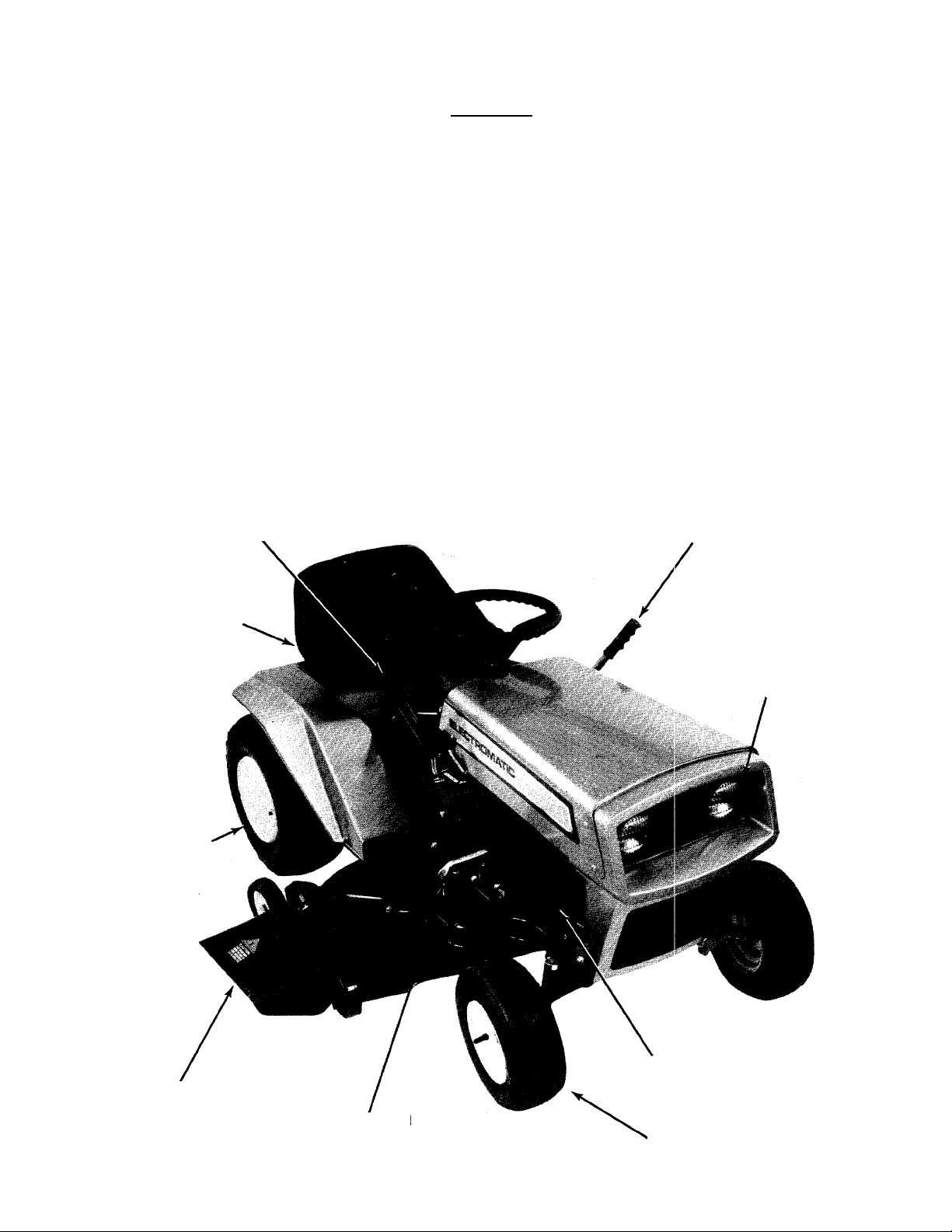
Lawn Mower Features
Blade Lift and Disengagement Lever
Lawn Mower Parts illustration................................. 18
Lawn Mower Parts List
Differential Parts Illustration and Parts List
Wiring Parts Illustration
Wiring Parts List
Traction Motor Parts Illustration and Parts List .. 28
Cutter Motor Parts Illustration and Parts List ... 29
Parts Information .................................................... 30
..........................................
............
..........................................
.....................................................
Clutch Lockout Lever
'.. 19
25
26
27
Adjustable Seat
18x6.50 Tires
Chute Deflector
Head Lamps
(36 Volt)
Three 12-Volt Batteries
Brake Peda
1 5x6.00 Tires
Page 4
Hints for Best Performance
This electric riding mower is the
ultimate in quietness and con
venience. It has its own character
istics that must be considered in
its operation. The "fuel" is in the
form of stored electricity in three
12-Volt batteries wired in series
to provide a 36-Volt system. The
gasoline engine and the electric
motor are similar in the way they
consume fuel (either gasoline or
electricity) by the fact that the
harder the unit is operated, the
faster the fuel is consumed. Cutting
at the maximum ground speed in
heavy grass will consume more
electrical energy than cutting at
an average speed in average or light
grass. The length of operating time
is in direct proportion to the way
the unit is driven and the cutting
conditions. As an example, the unit
will cut light grass for approxi
mately one hour at a modest
forward speed. That time may be
cut in half when cutting heavy grass
at high speed. The size of lawn to
be cut becomes the major influenc
ing factor in how the unit is used.
The built-in charging system takes
12 hours to 100% charge the
batteries.
Your riding mower is engineered
and designed to give you a mani
cured lawn with a minimum amount
of effort for the operator. The twin
blade cutting deck is designed to
effectively discharge the cut grass
from the deck onto the lawn or into
a grass catcher.
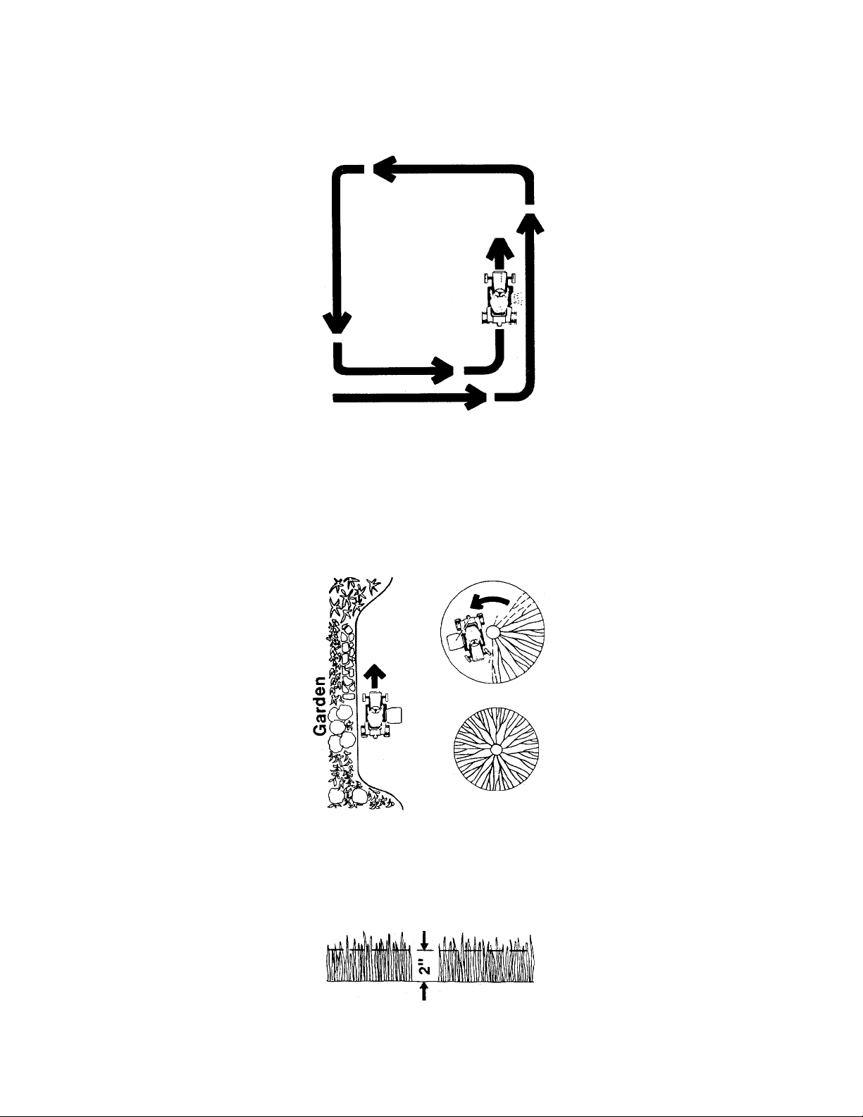
If you are cutting without a grass
catcher and the grass is wet, thick
or lush you should cut in a counter
clockwise direction to discharge
the grass towards the cut section of
your lawn. Recutting large amounts
of clippings will cause windrows
of grass.
When cutting with a grass catcher
kit, you can cut either clockwise or
counter clockwise. Plan your cutting
so you always trim with the left
side of the deck and have clearance
for the grass catcher.
Grasses such as Merion or Kentucky
Blue should not be cut less than 2
inches high. Infrequent cutting re
moves too much of the leaf surface.
Never cut off more than '/3 of the
grass blade.
It is important to have the blade
of your mower sharp when cutting.
Details on blade sharpening are ex
plained in the Maintenance Section
of this handbook. Cutting with a
dull blade generally results in a
white cast over a recent cut lawn
and later the tips of the blades turn
brown.
Avoid cutting wet grass because it
will clog up under the deck and will
not discharge properly. The general
appearance will be much better
when the grass is dry when you cut
it. A new lawn has much softer
blades of grass and has a higher
moisture content. It is extremely
important for this type of lawn to be
cut with a sharp blade.
Following the same pattern every
time when you mow your lawn can
develop ridges at right angles to the
direction of mowing. By changing
your direction of mowing (diagonal
or right angle) you can prevent
this.
Grass Catcher Model No. 194-01 5A
is available as optional equipment
for the mower shown in this manual.
Warning: The mower shall not be
operated wihout the entire grass
catcher or chute deflector in place.
Note: Under normal usage bag
material is subject to wear, and
should be checked periodically. Be
sure any replacement bag complies
with the mower manufacturer's
recommendations. Use factory
replacement bag No. 764-122.
Page 5
Assembly
NOTE: Reference to Left or Right
side of machine is from the oper
ator's position in the seat facing
forward.
The Riding Mower is packed and
shipped in one container and is
fully assembled except for the
steering wheel, seat and activating
the batteries.
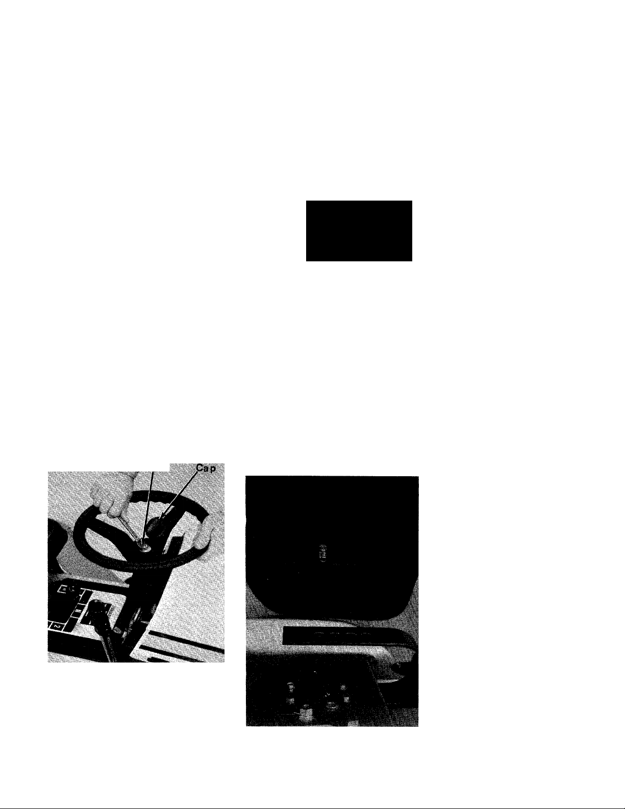
Attaching Steering Wheel
1 Place the steering wheel over
the steering column extending
through the dash. Line up the
flats on the steering column with
the flats in the steering wheel.
(See figure 1.)
2 Place the washer with the
cupped side down over the
steering column anu secure.
3 Place the cap over the center
of the steering wheel and seat
it with your hand.
Nut
Seat Assembly
1 Hook the carriage bolt into the
slot in the bottom of the seat
See Figure 1.
Carriage Bolt
nf-
Figure 2
2 Place the seat on the spring in
one of the four adjustment
holes. (See figure 3.)
3 Secure the seat with the large
lockwasher and nut.
i^ctivating the Batteries
^ Warning: ^
Electrolyte contains sul
phuric acid which is harmful to skin,
eyes and clothing. Avoid direct
contact with the electrolyte at all
times.
Fill batteries in an area where clean
water is available for flushing the
skin and eyes at all times.
Wear glasses (preferably safety
glasses) to protect the eyes while
handling electrolyte.
Electrolyte Antidotes
External: Flood with water, then
cover with moistened sodium bicar
bonate (baking soda). If eyes are
involved, wash first with water then
with 1 per cent solution of freshly
prepared sodium bicarbonate (bak-
ng soda). Call pyhsician immedi
ately.
Internal: Do not use emetics, stom
ach pumps, carbonates or bicar
bonates. Give at least 2 to 3 oz. of
milk of magnesia, or preferably
aluminum hydroxide gel diluted
with water. If these alkalies are not
available, the whites of eggs (2 to
3) well beaten may be used. Give
large quantities of water. Prevent
collapse. Call physician immedi
ately.
Figure 1
Figure 3
Page 6
Assembly
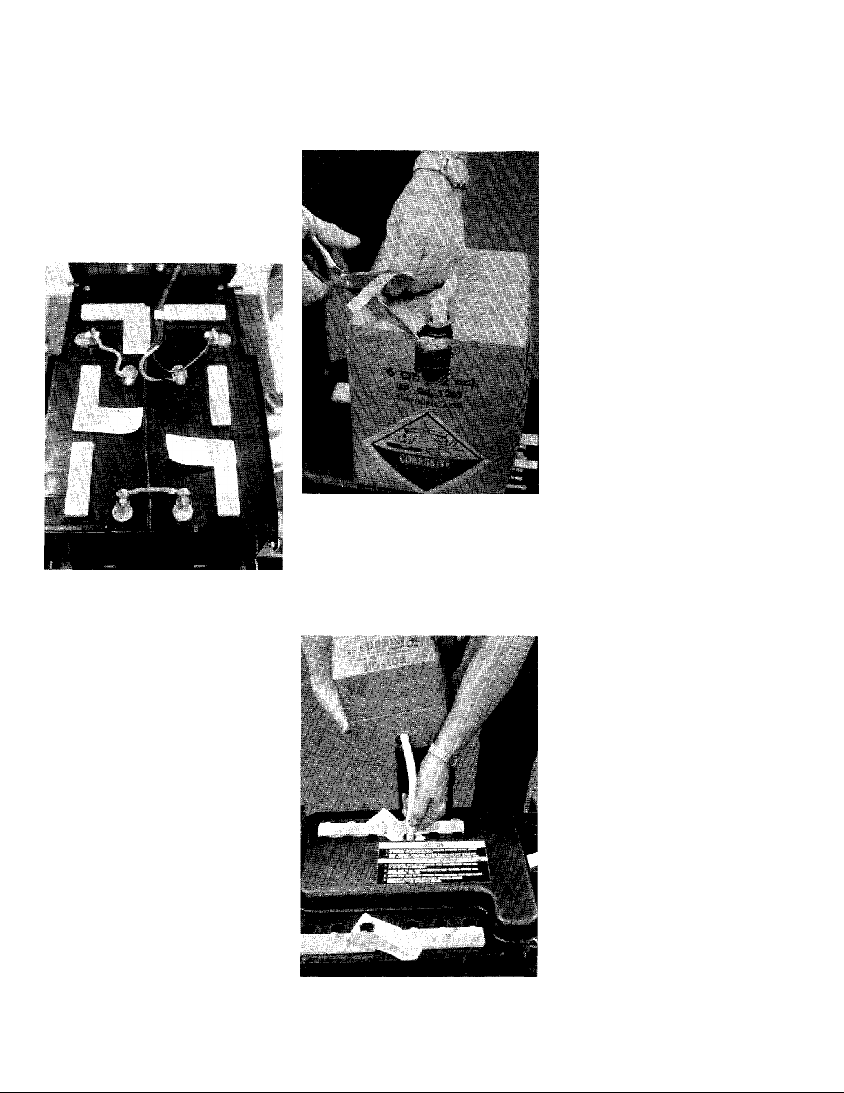
Compare the wiring of the bat
teries against figure 4 to be sur«
the batteries are wired as they
should be. Batteries that are
wired wrong could cause a
dead short when they are
activated.
Figure 4
2 It will be necessary to purchase
locally 18 quarts of Sulphuric
Acid Electrolyte (Sp. Gr, 1.265)
to activate the battery.
6 Charge the batteries as outlined
in the Maintenance Section of
this handbook.
7 Add the remaining acid to fill
the batteries to the split ring.
Tire Pressure
For shipping purposes, the tires on
your unit may be over-inflated. Tire
pressure should be reduced before
unit is put into operation. Pres
sure should not exceed 15 P.S.I.
Equal tire pressure should be
maintained.
Figure 5
Fill the batteries with the acid.
Only fill them until the acid
level is 14” above the plates.
Do not fill to the split ring at
this time.
3 Cut the sealed end from the fill
tube on the acid pack. (See
figure 5.)
4 Pinch the tube to keep the acid
from flowing from the tube
until you have the acid pack in
position as shown in figure 6.
Figure 6
Page 7
Operation
CAUTION
1 Keep al
place.
2 Before leaving operators posi
tion;
Shift transmission into neutral
Set the parking brake
Disengage the blade engage
ment lever
Shut off all motors
Remove ignition key
3 Wait for all movement to stop,
remove the ground v\/ire to the
battery before servicing the
machine.
4 Keep people and pets a safe
distance away from the ma
chine.
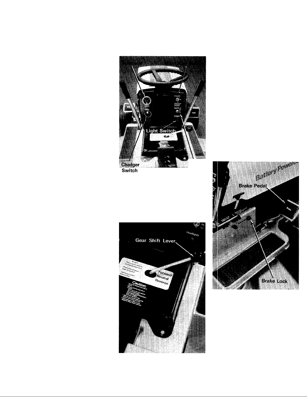
Main Key Switch
Turn the key to the START position
to start the traction motor. The
taction motor operates the drive to
the rear wheels. Once the motor
is running, release the key. The
switch will return to.the ON posi
tion. To stop the motor, turn the
key to the OFF position. This switch
must be in the ON position before
the blades can be operated. (See
figure 7.)
Caution; Remove the key from the
riding mower when the mower is
not in use to prevent accidental
starting.
shields and guards in
EJrake Pedal
The brake pedal is located on the
right side of the mower and is
operated by depressing it with your
right foot. When coming to a com
plete stop it is necessary to depress
both the clutch and the brake.(See
figure 9.)
Etrake Lock
The brake lock is located on the
right side of the mower. To lock
the brake, depress the brake pedal
and lift up the lock button. The
pedal will stay depressed. To re
lease, depress the pedal. (See fig
ure 9.)
Mother
Blade
Switch
Figure 7
Gear Shift Lever
The gear shift lever is used to shift
into FORWARD, NEUTRAL or RE
VERSE. (See figure 8.)
Mower Blade Switch
Raise the switch to the START
position. After the motors are
running, release the switch and it
will return to the ON position. Move
the switch to the OFF position to
stop the blades. The traction motor
fnust be running before the mower
blades can operate. Turning off the
main key switch will shut off both
the traction motor and the blade
motors. (See figure 7.)
Figure 9
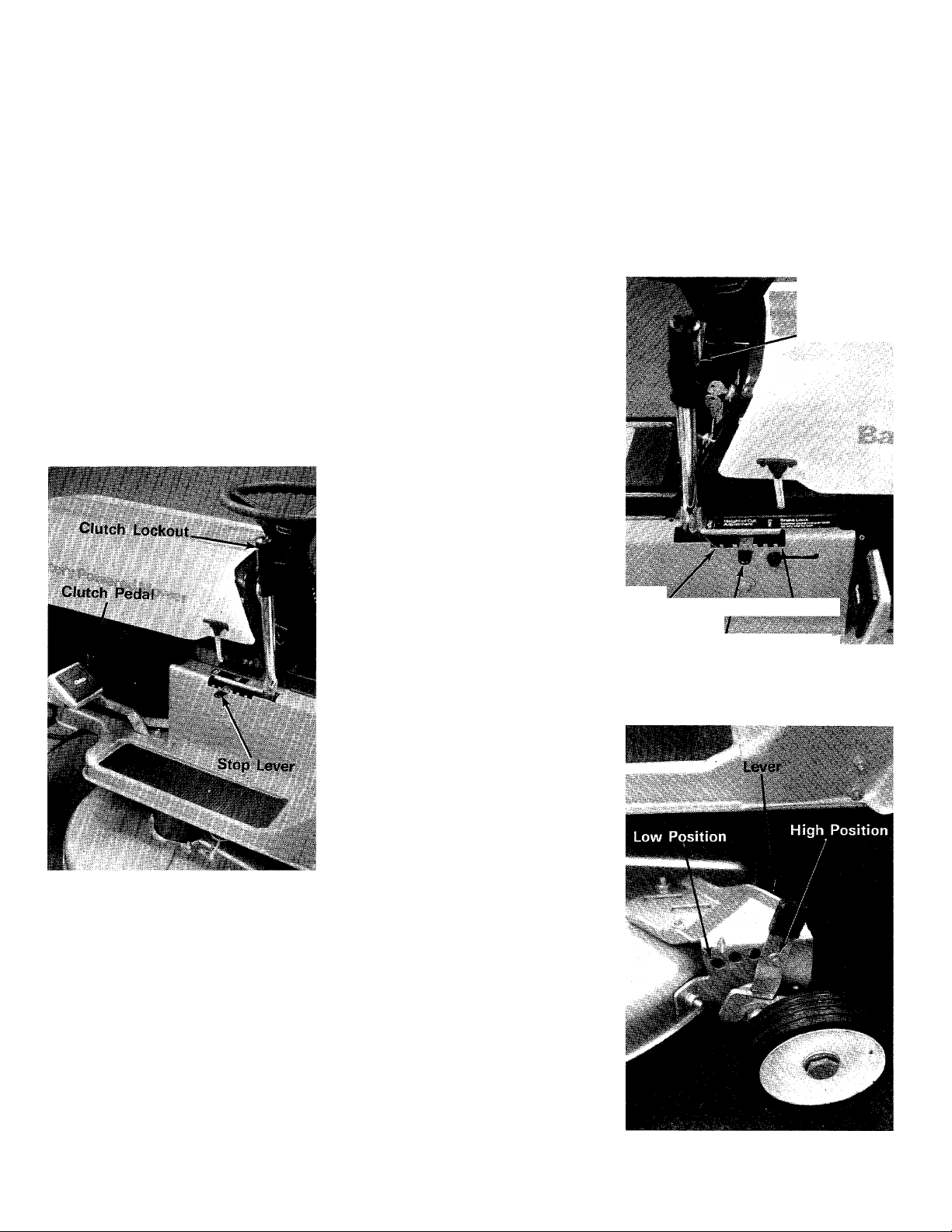
Clutch Pedal
The clutch pedal is used to dis
engage the drive mechanism.
Depressing the clutch pedal at any
time will slow you down or, if
depressed all the way, will stop the
mower. (See figure 10.)
Figure 8
Page 8
Operation
Clutch Lockout
When the clutch pedal is depressed
all the way it can be locked by
placing the clutch lockout in the
START position as shown in figure
10.
Stop Lever
The stop lever allows you to regu
late the nnaximunn ground speed
of the riding mower by setting the
stop lever in any one of the five
settings. The farther forward the
stop lever is set, the faster your
ground speed. (See figure 10.)
Charger Switch
This switch turns on the charger
to recharge the batteries. The cord
for the charger is located under
the hood. Details for charging the
batteries is in the Maintenance
Section of this handbook.. (See
figure 7.)
Lift Lever
The lift lever is used to raise the
cutting deck. (See figure 11.)
Cutting Controis
The cutting controls consist of the
height of cut stop and the wheel
height adjusters.
Height of Cut Stop
Lift the stop and set it at the de
sired cuting height. (See figure 11
To set the cutting deck in the sus
pended position, set the height of
cut stop in the desired cutting
height and then set the deck wheels
so they just clear the ground. (See
figure 12.)
Lift Lever
High Position/ Low Position
Figure 10.
Light Switch
The headlamps are operated by
pulling out the light switch located
on the dash board. The headlamps
will only operate when the traction
motor is running. (See figure 7.)
Ammeter
The ammeter registers the rate of
battery charge. It only registers
when the charger is plugged in and
the switch is in the ON position.
(See figure 7.)
Wheei Height Adjusters
Move the lever towards the wheel
and set it in the desired cutting
height. (See figure 12.)
There are six different cutting
heights. The cutting height can be
set in two different ways; FULL
FLOAT position where the deck
follows the contour of the ground,
and the SUSPENDED position
where the deck hangs from the
frame of the rider. The suspended
position is normally used for cutting
rough uneven ground.
To set the cutting deck in the full
float position, set the wheel height
adjusters in the desired cutting
height. Set the height of cut stop
in the low position. (See figure 11.)
Height of Cut Stop
Figure 11
Figure 12
Page 9
Operation
Starting the Traction Motor
1 Place the Clutch Lockout Lever
in the START position.
2 Turn the Main Key Switch to the
START position. As soon as
the motor is running, release the
key and the switch will return
to the ON position.
3 Turn the key to the OFF position
to stop the traction motor.
Note: The blade motors also shut
off if the Main Key Switch is turned
to the OFF position.
Starting the Biade Motors
1 Start the traction motor as
outlined in the paragraph above.
2 Raise'the Mower Blade Switch
to the START position. As soon
as the motors are running, re
lease the switch and it will re
turn to the ON position.
3 To stop the blades from ro
tating, depress the mower blade
switch to the OFF position.
Note: The blades will also shut off
when the Main Key Switch is turned
off.
WARNING
i
Do not attempt to clear the chute
or perform any cleaning or repairs
of the riding mower without
turning off the main key switch and
removing the key from the switch.
Operating the Mower
1 Set the desired cutting height.
2 Start the traction motor.
3 Set the clutch stop lever in the
slow or medium speed range.
Note: As you become familiar with
the operation of the mower you may
wish to move the stop lever to a
faster position.
t
4 While holding down the clutch
pedal, move the clutch lockout
lever forward.
5 Put the gear shift lever into
either FORWARD or REVERSE.
Note: Do not force the gear shift
lever. If the lever cannot be moved
from NEUTRAL to one of the
drive positions, release the clutch
pedal slowly, depress it again, and
then move the gear shift lever as
required.
6 Once the machine is in motion,
remove your foot from the
pedal. The mower will now move
ahead or to the rear, and the
use of the steering wheel will
provide directional control.
7 The mower is brought to a stop
by pressing your right foot
against the brake pedal and your
left foot against the clutch
pedal. The drive belt will be
disengaged and the brake will
be applied.
Note: The rider should be operated
in the slow speeds when climbing
a hill or descending. This reduces
the current draw going uphill and
retards the forward speed going
downhill.
Operating the Cutter Blades
The blades can be started either
while the mower is moving or
standing still.
Move the Mower Blade Switch to
the START position, as soon as the
motors are running, release the
switch and it will return to the ON
position.
To stop the blades from rotating,
depress the Mower Blade Switch
to the OFF position or.turn off the
Main Key Switch.
Note: When the riding mower is
being used for other than mowing
operations the blades should be
shut off.
Maintenance and adjustments for
the engine are covered in the Engine
Operating and Maintenance Instruc
tions section of this handbook.
I
Figure 13
Figure 14
Page 10

Maintenance
-1 ul ■* JK" Í/T.JSS-.i*
.....
Figure 15
Lubrication
Steering 1—Rack and pinion, lubri
cate with multi-purpose automotive
grease once a year. (See figure
13.)
King Pin 2—Oil with SAE 30 oil
once a year. (See figure 13.)
Wheel Bearings 3—Oil with SAE
30 oil four times a year. (See figure
13.)
Front Pivot Bolt 4—Oil with SAE
30 oil once a year. (See figure 13.)
Deck Wheels 5—Remove the axle
bolts and lubricate with multi-pur
pose automotive grease once a year.
(See figure 14.)
Rear Axle Bearings 6—Oil with
SAE 30 oil once a year. Four bear
ings. (See figure 13.)
Transmission 7—The transmission
is pre-lubricated and does not have
to be checked. If disassembled,
lubricate with 5 ounces of 450°F.
grease. (See figure 13.)
Differential 8—The differential is
pre-lubricated and does not have to
be checked. If disassembled lubri
cate with 2 ounces of 450°F.
grease. (See figure 13.)
Variable Speed Pivot 9—Lubricate
with SAE 30 oil or very light grease
I
every 25 hours or anytime the
clutch pedal operates stiff. Remove
the gear shift knob and transmis
sion cover to lubricate. (See figure
15.)
Variable Speed Pulley 10—Lightly
oil with SAE 10 oil so the center
section of the pulley slides up
and down freely. The two end
bearings are sealed and require no
lubrication.
General—The following parts
should be oiled once a year with
SAE 30 oil:
All deck links
Clutch and brake pivot points
and linkage
Fleight Adjustment Levers
Steering Column bearings
The following items have sealed
bearings and require no further
lubrication.
Idler Bearings
Tie Rod Ends
Battery Charger
WARNING
THE GASES PRODUCED WHILE
THE BATTERIES ARE BEING
CHARGED ARE HIGHLY COMBUS
TIBLE. THE HOOD SHOULD BE
RAISED UNTIL THE CHARGER
SWITCH RETURNS TO THE OFF
POSITION. KEEP OPEN FLAMES
AWAY FROM THE UNIT AND DO
NOT SMOKE IN THE AREA.
The batteries in your riding mower
are specially built to withstand re
peated charging without damage.
Whenever the mower is not being
used, the charger cord should be
plugged into a 110-1 25 volt AC
grounded outlet. The charger will
draw 7.5 amps, until the battery is
charged to 80% of its capacity,
and then it will taper off.
After the cord is plugged into the
outlet, turn the charger switch
clockwise until it stops. The timer
behind the switch will rotate it to the
OFF position at which time the
batteries will be charged to their
fullest capacity. The switch will
not begin to rotate until the batteries
have reached 80% of their capacity.
This will take approximately 5 hours
maximum.
Caution; Always turn the charger
switch to the OFF position before
removing the cord from the outlet.
The charger cord should be left
plugged into a live outlet at all times
when the mower is not in use. A
timer built into the charger will
automatically turn on the charger
once a day for a few minutes and
charge the batteries. This will keep
the batteries at full capacity. This
is very important during winter
storage. A battery will lose
50% of its capacity if it is
not used for a 90 day period.
This can cause a battery to freeze
and crack during extreme cold
weather. Some heat is generated
from the charger while it is oper
ating. This is normal. (See figure
16.)
10
Page 11

Maintenance
The ammeter shows you the rate
at which your batteries are charg
ing. Maximum charging rate
is approximately 7 to 8 amps. The
charging rate will drop to 3 amps
during the latter part of charging.
Battery Maintenance
Follow the instructions in the above
paragraph covering the charging
of the batteries. To charge a set
of batteries to 100% of capacity
will take a maximum of 12 hours.
Reading your ammeter during the
charging will give you an indication
of the state of charge of your bat
teries. If the ammeter reading is
over 6 Amps, you have less than
80% of capacity.
A hydrometer can be used to
check the state of charge of the
batteries. Always read a hydrometer
at eye level to obtain a true reading.
Keep the float vertical. A hy
drometer is designed to give the
correct reading at 80°F. This is
the electrolyte temperatuer, not the
air temperature. Draw enough elec
trolyte into the hydrometer so the
float does not touch the bottom of
the tube. A correction chart is
necessary to obtain a true reading.
(See figure 17.)
Temperature
°F.
120 -F.016
115
110
105
100
95
90 +.004
85
80
75
70
65 -.006
60
55 -.010
50 -.012
45 -.014
40
35 . -.018
30 -.020
25 -.022
20 ■ -.024
15 -.026
10
Figure 18
Correction Chart
Correction
+ .014
+ .012
+ .010
+ .008
+ .006
1 +.002
0
-.002
-.004
-.008
-.016
-.028
Figure 16
Charging Hints
1 Be sure the outlet used to
charge the battery is live and
does not shut off when you turn
off the lights.
2 Only use the charger built into
the mower to charge the bat
teries. Do not use any other
charger.
3 Do not use the battery in the
mower to “jump" any other
vehicle.
Figure 17
1.260 SpGr 1.280 SpGr 100% Chg
1.230 SpGr 1.250 SpGr 75% Chg
1.200 SpGr 1.220 SpGr 50% Chg
1.170 SpGr 1.190 SpGr 25% Chg
1.140 SpGr 1.160 SpGr Very little
1.110 SpGr 1.130 SpGr Discharged
Figure 19
Examples of Reading
Specific Gravity
Hydro. Read. (fig. 17) 1.230 SpGr
Electrolyte Temp. 30° F.
Temp, Correction (fig. 18) -.020
Corrected SpGr* 1.210 SpGr
Hydro. Read, (fig
Electrolye Temp.
Temp. Correction (fig
Corrected SpGr*
*Compare to figure 19.
useful capacity
1.230 SpGr
17)
100° F.
18) -F.008
1.238 SpGr
11
Page 12

Maintenance
Water
Drinking water, except mineral
water, may be used in the batteries.
If your local water has a high min
eral content (hard water) use
distilled water in your batteries.
Do not add electrolyte if the liquid
level is down, only water.
If you add water to the battery
it will lower the specific gravity of
the electrolyte but the battery has
not lost any of its charge. If water
is added during freezing weather be
sure you charge the battery as
outlined in Battery Charger para
graph. Failure to do this can freeze
and crack a battery.
Batteries that use excessive
amounts of water indicate that they
are being over-charged and the
riding mower should be examined
by a serviceman.
Battery Removal
If the batteries are removed from
the riding mower for any reason,
remove the plastic cover by pulling
the pins and unsnapping it. Remove
the cables in the order shown in
figure 20.
This will help prevent your wrench
from arcing if it slips.
Note: Refer to figure 20 when you
reconnect the battery to make sure
it is connected properly.
Headlamps
The headlamps are 36-Volt.
Use only authorized replacements.
(GE 4350 or order from the mower
manufacturer by part number
725-377)
Automatic Reset Breakers
For your protection, both the
traction motor and the mower blade
motors have automatic reset break
ers that will shut off the motors
if they overheat as a result of over
loading. Cutting high grass at an
excessive speed is a common cause
for overheating.
Caution: If one blade motor cuts
out from overheating, both motors
will stop.
If the automatic reset breaker on
the traction motor opens, it will take
about 30 minutes before it will
reset itself.
If the automatic reset breaker on
one of the blade motors opens, it
will take about five minutes before
they will reset themselves.
Fuse (Buss WDA 100)
The 100 Amp. fuse is located
inside the charger box in back of
the dashboard. Unsnap the plastic
cover to check the fuse. There are
three extra fuses in your assembly
pack. DO NOT SUBSTITUTE any
other fuse or any other material in
place of the correct fuse.
The fuse has two purposes. One is
to protect the wiring against a
direct short and the other is to pro
tect the electrical circuit against
overloads.
If either the traction motor or blade
motors are overworked for a long
period of time the automatic reset
breakers will open and the over
heated motor will shut off as ex
plained in the above paragraphs.
If a heavy surge of current is drawn
through either the traction motor
or blade motors the 100 Amp. fuse
can melt. An example of this would
be cutting heavy grass while climb
ing a hill at a fast ground speed.
Figure 20
In the event of a melted fuse, review
how the machine was operated
prior to fuse melting. If the machine
was not heavily loaded, a failure
within the circuitry may have
occurred and the reason
for it melting should be corrected
before a new fuse is installed.
To remove the fuse, remove the
plastic cover, loosen the two nuts
on each end of the fuse and take
the free ends off the two terminals.
Replace it with a Buss WDA 100
fuse. (Manufacturers number
725-376)
12
Page 13

Maintenance
Tighten the adjusting nuts equally
on both sides. Tighten until the
chain has V4 inch slack between
the sprockets.
Figure 21
Blade Replacement
Remove the retainer nut and lockwasher. Pull the blade from the
motor shaft. (See figure 22.)
Figure 23
Brake Adjustment
To adjust the brake on your rider,
follow these steps:
1 Depress the brake pedal and lift
the brake lock so the pedal
stays in the depressed position.
2 Place the clutch loc <out in the
START position.
3 Try to push the rider. If the rider
can be moved, tighten the
brake adjustment nut as shown
in figure 23.
Note: It is not necessary to tip the
rider up on end as shown in the
photograph. The adjusting nut can
be reached with the rider in the
normal operating position.
4 Tighten the adjustment nut one
turn and test the rider. Repeat
if necessary.
Figure 24
The adjusting nuts can be tightened
individually to align the rear axle
if necessary.
Tighten the four locknuts after the
adjustment is made.
Wheel Alignment
The caster (forward slant of the
king pin) and the camber (tilt of the
wheels out at the top) requires
no adjustment. Automotive steering
principles have been used to de
termine the caster and camber on
the rider. The front wheels should
toe-in Ys inch. See figure 25.)
To adjust follow these steps;
Figure 22
When grinding or filing the blade,
remove equal amounts of metal
from both edges to keep the blade
in balance.
Chain Adjustment
To tighten the chain, loosen the
two locknuts on each side of the
rear axle. (See figure 24.)
13
II Remove the elastic locknut and
drop the tie rod end from the
steering arm. (See figure 25.)
Page 14

Maintenance
2 Loosen the hex jam nut on the tie
rod.
3 Adjust the tie rod assembly for
correct wheel alignment.
Note: Dimension B should be ap
proximately Vs inch less than
dimension A.
4 To increase dimension B screw
the rod into the tie rod end.
5 To decrease dimension B un
screw the tire rod from the tie
rod end.
6 Reassemble the rod. Check
dimensions.
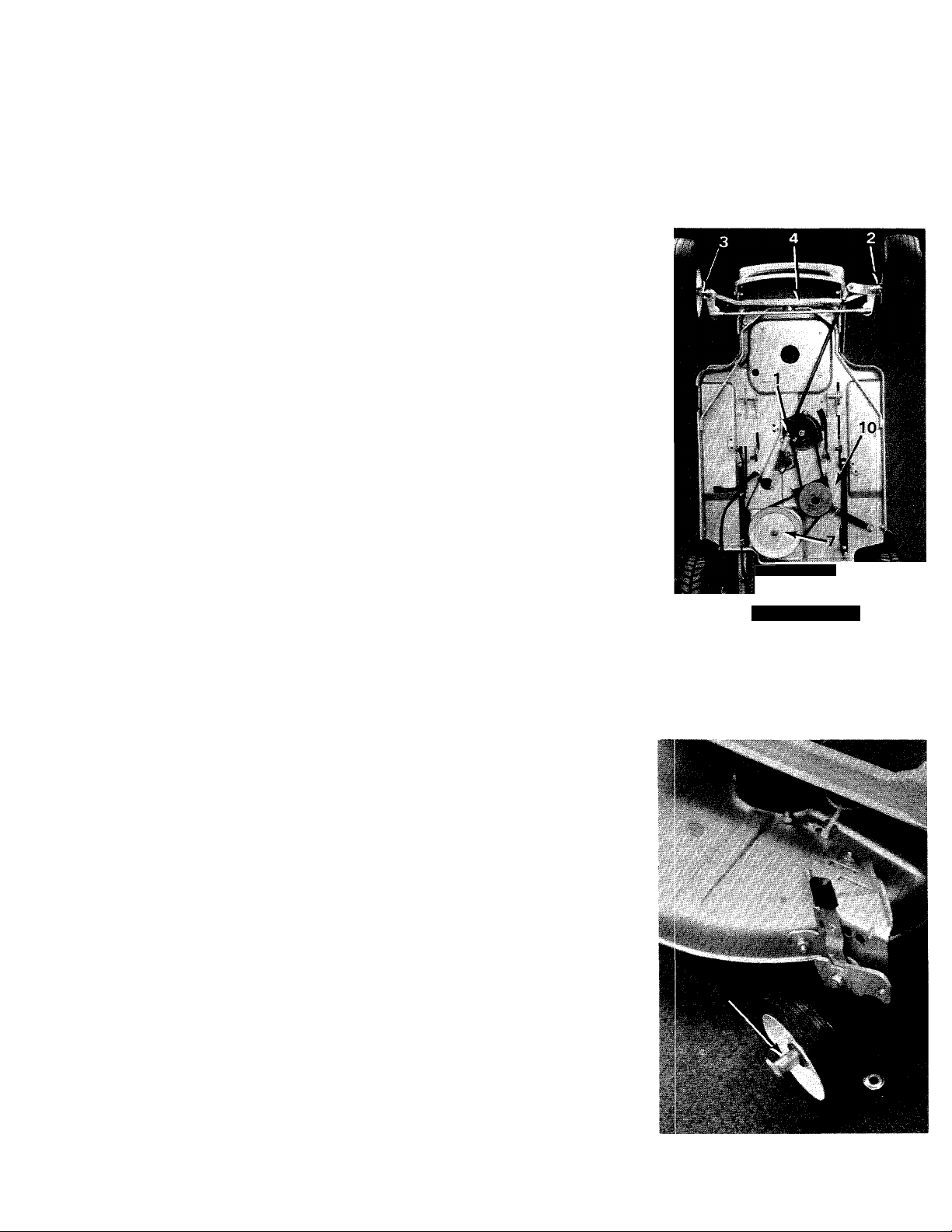
Removing the Variable Speed Belts
The variable speed belts can be
removed from the rider without
removing the cutting deck and
batteries, however, they can be
removed as the photographs show
to give you more working room.
To Remove the Batteries and
Cutting Deck
1 Before lifting up one end of the
mower, remove the batteries
as outlined in the Battery Re
moval Section of this manual.
2 Lift up the front of the rider and
tip it back so it rests on the
rear wheels and the seat back.
3 Remove the cutting deck by
unplugging the two leads to
the mower blade motors, and
removing the six cotter pins
on the lower deck links.
4 Place the lift lever in the locked
out position.
Motor Puiley
Upper Bolt*.
5 Remove the nut and lockwasher
on the transmission pulley and
pull the pulley off the spindle.
(See figure 27.)
6 Remove the lower belt from the
variable speed pulley. (See
figure 28.)
7 Slide the center section of the
variable speed pulley towards
you and unhook the upper belt.
8 Reassemble in reverse order
with the new belts
Figure 28
14
Page 15

Maintenance
Troubleshooting
If a problem is encountered which
cannot be solved, refer to the chart
on page 16 for a possible remedy.
Off-season Storage
If the machine is to be inoperative
for a period longer than 30 days,
the following procedures are
recommended:
1 Clean the entire mower and
motors thoroughly.
2 Lubricate all lubrication points
indicated in figures 13 to 15,
then wipe the entire machine
with an oiled rag in order to
protect the surfaces.
3 Check the water level in the
batteries and add water if
necessary.
4 Plug the charger into an outlet
that has power all the time. Set
the charger switch to the ON
position. When the batteries are
completely charged, the timer
will turn on the charger once a
day for a few minutes to keep
the batteries at full charge.
15
Page 16

Trouble Shooting Chart
Problem
Traction Motor will not run.
Blade motors will not run. A Traction motor not running.
Mower will not move (Traction Motor running)
A Clutch lockout is not in the START position.
B Defective key switch.
C Motor overheated from excessive current draw
Allow the automatic reset breaker to reset itself
This takes about 30 minutes.
D Main fuse blown.
E Defective solenoid.
F Wire loose or disconnected.
G Defective motor.
B Defective mower blade switch.
C Motor overheated from cutting heavy grass at
excessive speed. Allow the automatic reset
breaker to reset itself. This takes about five
minutes.
D Defective solenoid.
E Wire loose or disconnected.
F Defective motor.
A Transmission in neutral.
B Clutch lockout is in the START position.
C Broken or thrown V-belt.
D Broken chain on rear axle.
E Broken or missing key in transmission (input
pulley, output sprocket, clutch collar or pinion
gear on input shaft).
F Gears in differential stripped.
Ammeter registers zero when
charger is turned on.
Batteries will not hold a charge.
Uneven mowing. A Wheel adjusters are not set the same.
Uncut strips of grass.
A The charger is not plugged into a live outlet.
B Loose cables between the batteries.
C Loose wire in the charging system.
D Charger is not working.
E Fuse blown in the charger.
A Very low water level in batteries.
B Battery (or batteries) defective.
B Bent deck.
C Ground speed is too fast for full float cutting.
Adjust deck so it is suspended and reduce
speed.
D Low battery voltage.
A Ground speed too fast.
B Dull blades.
C Short blade(s).
D Bent deck.
E Low battery voltage.
16
Page 17

REF.
PART
NO.
COLOR
NO.
1
716-104
2
748-204 #41 Sprocket Center 8 Tooth
3
714-129
4
711-854
5
714-126
6
717-123
7
748-855
8 712-117
9
748-856 Bevel Gear
10
748-857 Clutch Collar
11
12
717-124 Transmission Case—R.H.—
'3
710-195
1
___
8583
CODE
E-Ring for .500" Dia. Shaft
#4 Hi-Pro Key 3/32 x %" Dia.
Output Shaft
#9 Hi-Pro Key 3/16 X %" Dia.
Transmission Case—L.H.
Flange Bearing
Hex Centerlock V4-28*
Shift Yoke Assembly
Hex Hd. Cap Scr. %-28 x .62"
DESCRIPTION
Complete
Comp. (Witb Detent Hole)
Lg.*
NEW
PART
REF.
PART
NO.
NO.
14
741-862
15 732-863
16 736-116
17 716-106
18 716-865
19
748-866
20 748-867
21 738-159
736-192
22
736-921
23
24 712-922
25 737-120 Greose—High Temp. 450° F.
717-222
26
COLOR
CODE
DESCRIPTION
Detent Ball
Detent Spring
Flat Washer .635 I.D. x .93
O.D.
E-Ring for .625" Dia. Shaft
Snap Ring for .500" Dia. Shaft
Pinion Gear
Bearing .627 I.D.
Pinion Shaft
Flat Washer .531 I.D. x .93
O.D.
Spring Lockwasher ’/2" Scr.*
Hex Jam Not ’/?-20 Thd.*
{5 oz.)
Transmission Complete
NEW
PART
*For faster service obtain standard nuts, bolts, and washers locally,
cally, order by part number and size as shown on parts list.
If these items cannot be obtained lo-
17
Page 18

134-585A
IF YOU WRITE TO US ABOUT THIS ARTICLE
OR IF YOU ORDER REPLACEMENT PARTS AL
WAYS MENTION THIS MODEL & SERIAL NO
MODEL
RIGHT HAND VIEW
18
Page 19

PARTS LIST FOR RIGHT HAND VIEW MODEL 134-585A
REF.
NO.
n
12
PART
NO.
723-296
712-287
13 710-289
14
736-119
COLOR
CODE DESCRIPTION
Hood Lock Ass'y.
Hex Nut'/4-20 Thd.*
Hex Scr. '/4-20 X .50" Lg.*
Spring Lockwasher 5/16"
Scr.*
15
16
712-267
—
Hex Nut 5/16-18 Thd.*
Lift Handle Ass'y. See
Breakdown
17
736-192 Flat Washer .531 I.D. x .93
O.D.
18 11869 Lockout Link Ass'y.
19
20
21
11494
11493
712-923
734-497
Lift Bracket—R.H.
Lift Bracket—L.H. (Not Shown)
Hex Center Locknut %-18 Thd.
Front Wheel Ass'y.—Comp.
15 X 6.00
734-498
Front Wheel Tire Only
22 734-499 Front Wheel Rim Ass'y. Only
23 710-312
Hex Scr. %-18 X 1.31" Lg.
24 711-169 Collar %" I.D.
25 750-207 Front Wheel Bearing
28 712-342 Hex Jam Nut %-16 Thd.*
29
30 10495
31
32
33
34
35
36
37
38
39
40
10555 Front Pivot Bar Ass'y.
Front Pivot Brkt.
710-195 Hex Scr. '/4-28 x .62" Lg.*
726-106
11399
Push On Flange Palnut
Adapter Plate Ass'y.
732-261 Torsion Spring
11633 Chute Cover Ass'y. Comp.
11574
712-193
11840
736-169
Chute Cover Ass'y.
Cone Nut %-24 Thd.
Upper Frame Cover
Spring Lockwasher %" Scr.*
736-232 Wave Washer .530" I.D. x
.78 O.D. X .013
NEW
PART
REF.
NO.
41
PART
NO.
738-234
COLOR
CODE
DESCRIPTION
Snoulder Scr. .500" Dia. x
.295
42
43
712-267
736-119
Hex Nut 5/16-18 Thd.*
Spring Lockwasher 5/1 6-1 6
Thd.*
44 710-198
Hex Hd. Sems Scr. 5/16-18
X 1.36"
45 732-255
714-107
46
47 11023
48 11056
Seat Spring
Internal Cotter Pin '/2" Dia.*
Deck Link Ass'y.
Parking Brake—Lever Ass'y.—
R.H.
726-121
49
50 8118
51 11030
52 710-201
Push Cap ’A" Dia.—Black
G'rip
L ft Handle R.H.
Hex Hd. Cap Scr. %-l 6 x
.62" Lg.*
53
736-219
Belleville Washer .400 I.D.
'x 1.13 O.D.
54 748-201
Spacer .635 I.D. x .88 O.D. x
.57
55
736-233
Wave Washer .660 I.D. x .82
O.D. X .029
56
57
58 731-208
11029 Handle Pivot Bracket
11032 Lift Handle Brkt. Ass'y.
Grille Insert
59 11031 Lift Handle L.H.
60 11034 Clutch Handle Brkt. Ass'y.
61
62
63
712-267
735-126
11027
Hex Nut 5/16-18 Thd.
Washer-Rubber
Handle Brkt. Assy.
64 Rubber Grip
NEW
PART
*For faster service obtain standard nuts and bolts locally. If these items
cannot be obtained locally, order by part number and size as shown
on the parts list.
(459-Mag. Flake)
When ordering parts, if color or finish is important use the appropriate
color code shown above (e.g. Mag Flake finish—11839 (459).)
19
Page 20

134-585A
IF YOU WRITE TO US ABOUT THIS ARTICLE
OR IF YOU ORDER REPLACEMENT PARTS AL
WAYS MENTION THIS MODEL & SERIAL NO
MODEL
LEFT HAND VIEW
20
Page 21

PARTS LIST FOR LEFT HAND VIEW MODEL 134-585A
REF.
NO.
1
2
PART
NO.
731-220
712-158
COLOR
CODE
DESCRIPTION
Steering Wheel Cap
Hex Center Locknut 5/16-18
Thd.
4
3
5
6
736-219
731-219
712-222
736-174
Belleville Washer .400" I.D. 30
X 1.13 O.D.
Steering Wheel 12.0 Dia.
Push Nut%" Dia.
Wave Washer .660" I.D. x
.88 O.D. X .50" Lg.*
7
738-200
8
757-241 Seat Ass'y. Comp.—10.0"
9
736-921 Spring Lockwasher ’/2" Scr.*
10
712-206
11
12
11839-
734-528
—459
Steering Shaft
Hex Nut V2-I 3 Thd.
Rear Fender
Rear Wheel Ass'y.—Comp,
18 X 6.50
734-294
Rear Wheel Tire Only 18 x
6.50
13
14
15
9262
10473
710-258 Hex Hd. Cap Scr. L4-20 x
Rear Wheel Rim Ass'y.
Rear Wheel Hub Ass'y.
.62" Lg.*
16
710-198 Hex Sems Scr. 5/16-18 x
.75" Lg.*
17
725-358
18
712-267 Hex Nut 5/16-18 Thd.*
19
736-119 Spring Lockwasher 5/16"
Cutter Motor 36 Volts
Scr.*
723-241
20
Foot Pad 15.75" Lg. x 4.0"
Wide
21
710-259 Hex Sems Scr. 5/16-18 x
.62" Lg.*
22
23
24
25
9098 Front Axle Ass'y. L.H.
723-156 Ball Joint Ass'y. (Tie Rod End)
711-169
710-494
Collar %" I.D.
Sq. Hd. Set Scr. 5/16-18 x
.38 Cup Pt.
^6
711-256
Tie Rod %-24 (Threaded Both
Ends)
NEW
PART
REF.
NO.
27
PART
NO.
748-184 Flange Bearing .630 I.D,
28 723-156
29
719-197
31 11836—459
32 712-287
33 736-329
34 710-286
35 712-375
COLOR
CODE
DESCRIPTION
Ball Joint Ass'y. (Tie Rod End)
9095 Front Axle Ass'y. R.H.
Front Grille Comp.
Front Hood
Hex Nut ’/4-20 Thd.*
Spring Lockwasher Vi" Scr.*
Truss Hd. Mach. Scr. Vi-20
Hex Center Locknut %-16 Thd.
36 11488 Dash Panel
37
38
736-105
710-253
Belleville Washer
Hex Hd. Cap Scr. %-l 6 x
1.00" Lg.*
39 747-138
40
41
42
43
—
735-156
12381
748-228 Hex Flange Bearing ,505 I.D.
Steering Rod
Steering Ass'y. See Breakdown
Headlight Door Mounting
Dash Panel—Box Ass'y.
Bronze
44 12372 Steering Rod Bracket
710-412 Hex Hd. Cap Scr. Vi-28 x .75"
45
Lg.*
46
47
11048 Steering Segment
1 1074
Steering Housing Ass'y.
48 715-120 Spring Pin Spirol %" Dia. x
1.00" Lg.
736-329
49
Spring Lockwasher Vi" Scr.*
50 712-138 Hex Nut ’/4-28 Thd.*
710-412 Hex Scr. ’/4-28 x .75" Lg.*
51
731-232 Dash Panel Cover
52
712-267
53
725-377 36 Volt Headlight
54
Hex Nut 5/16-18 Thd.*
57 1 1487 Upper Frame
58 710-473
59 736-147
60 712-425
61 731-310
Tuss Mach. Scr. #10-24 x.50" Lg.
Ext. L-Wash. #10 Scr.*
Sq. Nut #10-24 Thd.*
Shield
NEW
PART
N
N
N
*For fatter service obtain standard nuts and bolts locally. If these items
cannot be obtained locally, order by part number and size as shown
on the parts list.
21
(459—Mag. Flake)
When ordering parts, if color or finish is important use the appropriate
color code shown above (e.g. Mag Flake finish—11839 (459).)
Page 22

134-585A
-U9
no \ ns
KJ
74?
^ I ^ ■''
/
4
''
DECK AND FRAME VIEW
22
Page 23

PARTS LIST FOR DECK AND FRAME VIEW MODEL 134-585A
PART
REF.
NO.
1 7 25 -3 74
2 7 31 -2 33
3 7 36 -1 75
4 71 2-2 8 7
5 114 92
6 1149 1
7
736 -1 75
8 7 10 -2 89 He x S c r. ' /4- 20 X .50" Lg .*
710 -2 59 H ex S em s S cr. 5/ 1 6-1 8 x
9
10 71 2- 28 7 Hex N ut /4- 20 T hd .*
1 1
736 -1 75
12
13
710 -2 86
14 7 10 -2 86
15
16 1061 4 Peda l P a d V in yl
17
712 -7 98 Hex N ut % -1 6 T h d.*
18 7 36 -1 69 Sprin g Lo ck wa sh er % " Sc r'. *
19
738 -1 40 S h ou lde r Sc r. .43 7 " D ia . x
20 1109 4 Clu tc h C o nn ec tin g Br kt.
21 ‘
‘71 0-3 2 2 Hex S em s Sc r. 5/ 16 -1 8 x
22 714 -1 29
23
726 -1 00
24
732 -2 45
25
710 -1 98 He x S e ms S cr . 5 /1 6- 18 x
26
738 -2 13 S ho uld e r S cr . .4 98 " Dia . x
27
28 7 12 -2 67
29
736 -1 19
COLOR
CODE DESCRIPTION
NO.
12 Vo lt B a tte ry — De ep
Cyc le (3 )
Bat te ry Co ve r
Spr in g W a sh er .2 70 " I .D . x
.51 O. D. X .030
Hex N u t ’/4 -2 0 Th d .*
Bat te ry Ho ld B rac ke t
Bat te ry Pl ate
Spr in g W a sh er .2 70 " I .D . x
.51 O. D. X .030
,62 " L g.*
Spr in g W a sh er .2 70 " I .D . x
.51 O. D X .030
1 1 49 0
110 37 Clu tch P e da l A ss 'y.
1 1 03 9 Ped a l "U " -B rkt . A ss 'y.
Bat te ry Si de P an el— R .H .
Truss Mach. Scr. Vi-2 0 x . 50 " Lg.*
Truss Mach. Scr. 14-20 x .50"
.18 0
1.0 0" Lq
#4 Hi- Pr o- Ke y 3/3 2 x / s" D ia.
Pus h Nu t % " R od
Bra ke S pr ing
.75 " L g.*
1.4 50 " L g.
Hex N u t 5 /16 -1 8 Th d. *
Spr in g L oc kw a sh er 5/ 16 "
Scr.*
30 712 -26 7
31
1 1 48 9
32
118 71
33
736 -1 19
Hex N u t 5 /16 -1 8 Th d. *
Bat te ry Si de P an el— L .H .
Frame Ass 'y. —Lower
Spring Lockwasher 5/16"
Scr.*
34
35
36
712 -2 67
114 95
736 -1 19
Hex N u t5/ 16 -1 8 T h d.*
Motor Belt Guard
Spring Lockwasher 5/16"
Scr.*
37
38
39
40
41
712 -2 67
756 -2 07
712 -9 22
736-921
712 -2 67
Hex Nut 5/16-18" Thd.*
Motor Pulley 3.00" O.D. Split
Hex Jam Nut %-20 Thd.
Spring Lockwasher V2“ Scr.*
Hex Nut 5/16-18" Thd.*
NEW
PART
Lg.*
REF.
NO.
PART
NO.
42
736 -1 1 9 Spri ng Lo ck w as he r 5 /1 6"
43
754 -1 57 " V" -3 elt 2 1/3 2- 28 " L g .
44
710 -5 1 5
45 10438
46
47 74 8- 17 7
48 71 5- 12 4
49
748 -1 8
50
750 -1 44
51
750 -1 46
52
741 -1 39
53
725 -3 58
54
55
742 -1 36
56
736 -1 58 S p rin g Lo ck wa sh er %" Sc r.*
57
712 -2 42
58
710 -1 98
59
710 -2 89
60
71 1-5 7 1
61
62
710 -1 95
63
732 -2 61
64
65
726 -1 06
66
738 -1 1 9
67
734 -2 95
68 712 -1 1
69
736 -1 05
70
71
736 -1 05
72
73
74
736 -3 29
75
712 -2 87
76 7 36 -1 1
77
712 -2 67
78
712 -9 22
79
736-921
80
754 -1 36
81
756 -1 74
82
714 -1 29
COLOR
CODE
123 90
1
114 97 — 4 52
113 99
115 74 — 4 59
6
109 49
109 37
112 36
112 37
9
DESCRIPTION
Scr .*
Hex H d . C ap S cr . /2 -2 0 x
3,5 0" Lg .*
Var ia ble S pe ed P ul ley A ss 'y .
38. 0" Ele c . R id er D ec k A s s'y .
She a ve H alf
Spr in g P in — Sp ir ol 5/3 2" D ia .
x .6 2" Lg .*
Mo va ble S he a ve P art A ss 'y.
Ste el Tu bin g
Spa ce r .52 0" I. D. x .69 2 O. D,
Ball B ea rin g .5 0" I.D . x 1 .3 8"
C.D ,
Cut ter M ot or 36 V olt s
Dec k As s'y . Co m p.
19. 0 i nc h B la de
Hex J am N u t % -l 1" T hd .*
Hex S em s S cr, 5 /16 -1 8 x
.75 " L g.*
Hex S cr . ’/ 4-20 X .50" Lg .*
Piv ot Pin
Ada p ter P lat e A s s'y .
Hex S cr . ’A -2 8 x . 62 " L g .*
Tor s o n S prin g
Chu te C ov er A ss 'y.
Pus h Nu t ’ A" R od
Sho u lde r S c r. . 62 5" D ia. x
1.7 5" Lg .
Wh ee l A ss 'y . 5 .0" D ia .
Hex In se rt ed L oc kn ut % -2 4
Thd .
Bell ev ille W a sh e r
Spr in g L ev er A ss 'y. w ith K no b
Bell ev ille W a sh e r
Wh ee l P iv ot Ba r
Wh ee l B ra ck et A ss 'y.— R .H .
Wh ee l B ra ck et A ss 'y.— L .H .
Not C al led O ut
Spring Lockwasher ’A" Scr.*
Hex N u t /4-20 Thd.*
Spring Lockwasher 5/Id"
Scr .*
Hex N u t 5/16-18" Thd.*
Hex Jam Nut /2-20 Thd.
Spring Lockwasher /2" Scr.*
"V"-Belt 21/32 X 31." Lg.
Transmission Pulley .50" I.D.
#4 Hi-Pro-Key 3/32 x %" Dia.
NEW
PART
N
*For faster service obtain standard nuts and bolts locally. If these items
cannot be obtained locally, order by part number and size as shown
on the parts- list.
(459—Mag. Flake)
When ordering parts, if color or finish Is important use the appropriate
color code shown above (e.g. Mag Flake finish—11839 (459).)
23
Page 24

PARTS LIST (CONTINUED) FOR DECK AND FRAME VIEW MODEL 134-585A
REF.
NO.
PART
NO.
711-494 Spacer .510" I.D. x .760 O.D.
83
DESCRIPTION
X .390
711-242 Spacer .380" I.D. x 1.010 x
84
.320
736-119
85
712-429
86
87 712-798
736-169
88
11069 Variable Speed Plate Ass'y.
89
90
91
92 710-376
93
94
95
96
97 712-429 Hex Inserted Locknut 5/16-
98
99
100
101
102
103
104 11067
105 736-114
106 11056
107
108 736-119
109 11024
110 761-137
1 11 HH-02-03631
112
113'
116
11036 Brake Pedal Brkt. Ass'y.
11065
732-208 Variable Drive Spring
725-357 Traction Motor 36 Volts
714-507
11064 Clutch Rod—Vari. Spd.
11072
711-404
736-244
712-429
736-264
719-922
712-267
HH-06-03031
HH-05-03034
710-316
Spring ockwasher 5/1 6"
Scr.*
Hex Inserted Locknut 5/16-
18 Thd.
Hex Nut %-16 Thd.*
Spring Lockwasher %" Scr.*
Vari. Spd.—Beit Guard Ass'y.
Hex Scr. 5/16-18 x 1.00" Lg.*
Cotter Pin 3/32" Dia. x .75"
Lg.*
18 Thd.
Variable Speed—Link
Shoulder Nut
Flat Washer .141 I.D. x .28
O.D.
Hex Inserted Locknut 5/16-
18 Thd.
Flat Washer .344" I.D. x .62"
O.D.
Hex Jam Nut 1/2-20 Thd.
Vari. Speed—Eccenter Ass'y.
Internal Lockwasher I/2" Scr.*
Parking Brake—Lever Ass'y.—
R.H.
Hex Nut 5/16-18 Thd.*
Spring Lockwasher 5/16"
Scr.*
Deck Link
Disc Brake Ass'y.—Comp.
Locknut
Compression Spring
Push Pin
Hex Scr. %-16 X 3.50" Lg.
NEW
PART
REF.
NO.
114 HH-03-03097
115
1 17 761-138
118
119 HH-12-03045
120
121 HH-18-02770
122
123 712-429 Hex Inserted Locknut 5/16-
124 10364 Rear Axle Plate
125
126
128
129 10360
130
131 710-198
132
133
134
135 747-106
136 712-267
137
138
139 710-412
140 722-115
141
142 736-329
143
144 714-115
145 10396
146 710-289
147
148 731-309
149
PART
NO.
HH-15-02533
HH-12-03041
712-375 Hex Center Locknut %-16 Thd.
HH-03-03032
710-437
748-151
712-429
10362
732-157
736-119
10398
713-160
713-154
Friction Pad 1.600 Dia. x .370 T
# 420 Chain Vz" Pitch x 87
717-222
11853
712-138
746-133
714-101
DESCRIPTION
Backup-Wash.
Spacer for Disc Brake
Casting, Cam Side
Casting, Carrier Side
Cam Lever
Thrust Washer 5/16" I.D.
18 Thd.
Chain Adjusting Link 5/16-
18 X 4.38" Lg.
Flange Bearing with Flats
.753 I.D.
Hex Inserted Locknut 5/16-
18 Thd.
Axle Bolt Plate Ass'y.
Rear Axle Brkt. Ass'y.
Hex Sems Scr. 5/ 16-1 8 x
.75" Lg.*
Spring .38 O.D. x 3.25
Spring Lockwasher 5/16"
Scr.*
Disc Brake Brkt. Ass'y.'
Brake Rod .25" Dia. x 23.50".,
Lg-
Hex Nut5/16-18 Thd.*
Links
#420 Master Link Vz" Pitch
Type II
Single Speed Transmission Ass'y.
Hex Scr. ’/4-28 x .75" Lg.*
Ball Knob—Black
Transmission Shift Lever Ass'y.
Spring Lockwasher Scr.*
Hex Nut ’/4-28 Thd.*
Cotter Pin ’/a" Dia. x 1.00" Lg.*
Transmission Support Brkt. Ass'y.
Hex Scr. ’/4-20 X .50" Lg.*
Wire Clip—Open Type
Bushing
Intern. Cot. Pin Vz Dia.
NEV
PA
ik.
-
N
*For faster service obtain standard nuts and bolts locally. If these items
cannot be obtained locally, order by part number and size as shown
on the parts list.
(459—Mag. Flake)
When ordering parts, if color or finish is important use the appropriate
color code shown above (e.g. Mag Flake finish—11839 (459).)
24
Page 25

DIFFERENTIAL 10483
12 15
PARTS LIST FOR DIFFERENTIAL 10483
REF.
NO.
PART
NO.
719-150
1
2 738-130
738-13
3
748-185
4
748-158
5
711-276
6
736-187
7
736-188
8
9 9133
715-247
10
11 710-526
712-237
12
719-150
13
14 715-123
15 736-119
16 748-169
17
737-120
COLOR
CODE
DESCRIPTION
Housing Half (1)
Shaft-—Short (1)
Shaft—Long (1)
Gear—-Double "D" Hole (2)
Gear—Round Hole (2)
Drive Pin (1)
Flat Washer (2)
Washer (2)
Sprocket (1)
Spirol Pin 3/16" Dia. X 1.00"
Lg.* (2)
Hex Hd. Cap Scr. 5/16-24 x
4.00" Lg.* (4)
Hex Locknut 5/16-24 Thd. (4)
Housing Half (1)
Dowel Pin 3/16" Dia. x .62"
Lg. (2)
Spring Lockwasher 5/16"
Scr.* (8)
Flange Bearing (2)
Grease—High Temp. 450°F.
(2 oz.)
NEW
_PAfiI
*For faster service obtain standard nuts, bolts, and washers locally. If these items cannot be obtained lo
cally, order by part number and size as shown on parts list.
25
Page 26

Page 27

REF.
NO.
1
10
11
12
2
3
4
5
6
7
8
9
PART
NO.
725-377
725-388
725-358
725-358
725-376
725-373
725-268
725-150
725-389
725-370
725-374
725-369
PARTS LIST FOR SCHEMATIC
COLOR
CODE
36 Volt DC Headlight 13
Electric Wire
Cutter Motor R.
Cutter Motor L.
Fuse too
Diode
Safety Switch (Normally Open) 18
Electric Wire 8 Ga.-Red
Electric Wire
Solenoid—36 Volt
12 Volt Battery 21
Solenoid—36 Volt
DESCRIPTION
NEW
PART
REF.
NO.
PART
725-378
725-371
14
725-201
725-372
15
725-357 Drive Motor
16
725-202
17
725-386
725-368
19
725-440
710-198
20
736-119
712-267
22
NO.
COLOR
CODE
DESCRIPTION
Metal Strip
Ignition Switch
Ignition Key (Not Shown)
Cutter Switch
Light Switch
Ammeter
Motor Harness
Wire Harness N
Hex Sems Scr. 5/16-18 x .75" Lg.*
L-Wash. 5/16" Scr.*
Hex Nut 5/16-18 Thd.*
’7ó?S‘-37S' 36~i/.
NEW
PART
Black and
Stripped Green
Red
Harness Connector Looking into
Plug Motor Marked IL
Red
Yellow
Green
czif—Green
Drive Motor Connector Looking into Plug
Black Bridge Wire
Black
710-117 Hex Scr. (5/16-24x1.00)
736-242 Bell Wash (5/16)
736-249 Fib. Wash (.34 I.D. x 1.00 O.D. x .063)
736-248 Fib. Wash (.34 I.D. x .62 O.D. x .063)
3 Fib. Wash (.34 I.D. x 1.00 O.D. x .063)
Red Bridge Wire
Reid
Harness Connector Looking into
Plug Motor Marked IR
Red and Orange
Black
-242 Bell Wash (5/16)
Terminal
712-256 Hex
736-159 FI.
27
Jam Nut (5/16-24)
Vl/asher (5/16)
-376 Fuse (100 Amp.)
725-
,736-159
,712-256
Page 28

Traction Motor
2
3 4
20 21 22
Q ;■«
5
Model 725-357 C BOSH 06277-21-M048HM
REF.
NO.
1 01 137-21-SC48HM
2 06330-25-CP48HM
3
4 01225-25-BB48HM
5 01144-26-PL48HAA Plate, Bearing Retainer
6
7
8 06331-23-HC48HM
9
10 EC 3164
11
PART
NO.
Scr., Bearing Retainer Plate
Cap, Drive End-Vent
Not required
01 141-23-SC48HM Thru Bolts
06327-21-AT48HM
01 11 3-25-SC48HM
01219-24-BR48HM
Bearing, Drive End
Armature Assembly
Hsg., Assy., Motor-Vent
Scrs., Brush Holder Retain.
Retainer, Brush Shunt
Brush & Bolt Assy.
DESCRIPTION
PARTS LIST
REF.
NO.
12 SP 551013 Brush Spring
13 01112-27-BH48HM
14 SC 3080-1
15 EC 3046-4 Holder, Motor Protector
01238-20-SW48HM
16
17 01111-29-BG48HM Bearing, Commutator Cap
01216-22-WA48HM Washer, Insulating
18
19 06328-23-CP48HM
20 WA 3074-1 Washer, Insulating
21
WA 1 -9 CA or ZN
22 NT 7-8 CA or ZN Nut
PART
NO.
Brush Holder
Scr., Motor Protector Holder
Cap, Commutator End
Washer
DESCRIPTION
Motor Protector & Bracket
28
Page 29

Cutter Motor
2
3 4
Il 18
Vli
r’/ Il
5
14
—^ 16-
REF.
NO.
01137-21-SC48HM
1
PART
NO.
2 01149-24-CP48HM
01138-23-RG48HM
3
01127-22-BB48HM
4
01144-26-PL48HM
5
01140-25-SC48HM
6
01 173-22-AT48HM
7
01162-23-HG48HM
8
01 113-25-SC48HM
9
EC 3164
10
Model 725-358 (01119-27-M048HM)
DESCRIPTION
Screw, Bearing Retainer
Cap, Drive End
Ring, Retaining
Bearing, Drive End
Plate, Bearing Retaining
Thru Bolts
Armature Assembly
Housing Assembly, Motor
Screw, Brush Holder
Retainer, Brush Shunt
PARTS LIST
REF.
NO.
1 lA 01107-24-CB48HM Brush & Cable Assembly
12
SP 551013
13
01112-27-BH48HM Brush Holder
14
SC 3080-1
16A
01217-20-SW48HM
17
01111-29-BG48HM
18 Not required
01148-22-CP48HM
19A
PART
NO.
Brush Spring
Screw, Thermal Overload
Retainer
Thermal Overload Switch &
Cable Assy.
Bearing, Commutator Cap
Cap, Commutator End
DESCRIPTION
29
Page 30

PARTS INFORMATION
POWER EQUIPMENT PARTS AND SERVICE
Parts and service for all MTD manufactured power
equipment are available through the authorized serv
ice firms listed below. All orders should specify the
model number of your unit, parts numbers, descrip
tion of parts and the quantity of each part required.
A 1 Engine & Mower Co.
327 East 9th Street
Salt Lake City, Utah 84102
American Eieetric Ignition Co.
124 N. W. 8th Street
Oklahoma City, Oklahoma 73102
Auto Eieetric & Carburetor Co.
2S25 4th Avenue, S.
P. O. Box 1948
Birmingham, Alabama 35233
Automotive Equipment Service Co.
3117 Holmes Street
Kansas City, Missouri 64109
Bailey's Rebuild inc.
1325 E. Madison Street
Seattle Washington 98102
Bleckrie, Inc.
7900 Lorain Avenue
Cleveland, Ohio 44102
Brown Equipment Distributor Inc.
110 Beech Street
Corydon, Indiana 47112
Bullard Supply
2409 Commerce Street
Houston, Texas 77003
Carl A. Anderson Co.
623 S. 16th Street
Omaha, Nebraska 68102
Catto A Putty, Inc.
P. O. Box 2408
510 Soledad Street
San Antonio, Texas 78205
Center Supply Company
6867 New Hampshire Avenue
Takoma Park, Maryland 20012
Dixie Sales Company
P. O. Box 1408
327 Battleground Avenue
Greensboro, North Carolina 27402
East Point Cycle & Key Shop
1617 Whiteway
East Point, Georgia 30044
Gamble Distributors
West End Avenue
Carthage, New York 13619
Garden Equipment Co., Inc.
6600 Cherry Avenue
Long Beach, California 90805
Gardenville Supply, Inc.
Pipersville, Pennsylvania 18947
Henry W. O'Neil & Assoc., Inc.
410 North Goodman Street
Rochester, New York 14609
Henzier, Inc.
2015 Lemay Ferry Road
St. Louis, Missouri 63125
Kenton Supply
8216 North Denver Avenue
Portland, Oregon 97217
Kimber't Inc.
115 W. Geddes St.
Syracuse, New York 13204
The Lawnmower Shop
1340 El Camino Real
San Carlos, California 94070
Marr Brothers
423 E. Jefferson
Dallas, Texas 75203
Mathews Auto Electric Co.
420 East 2nd Street
Tulsa Oklahoma 74120
McClure Lawn & Garden Supply
1114 Lexington Avenue
Mansfield, Ohio 44907
Memphis Cycle & Supply Co.
421 Monroe Avenue
Memphis Tennessee 38103
Morton B. Collins Co.
300 Birnie Avenue
Springfield, Massachusetts 01107
Moz-AII of Florida, Inc.
365 Greco Avenue
Coral Gables, Florida 33146
DEFECTIVE OR MISSING PARTS must be reported
to the factory immediately. Such claims must include
your model number and date of purchase.
National Central, Div. of
Joe Sterling, Inc.
Drawer "D" 687 Seville Rd.
Wadsworth, Ohio 44281
Parts & Sales Inc.
2101 Industrial Pkwy.
Elkhart, Indiana 46514
Power Equipment Distributor
36463 So. Gratiot Avenue
Mt. Clemens, Michigan 48043
Power Lawn & Garden Equip. Co.
2551-2571 J. F. Kennedy Road
Dubuque, Iowa 52001
Radco Distributors
2403 Market Street
P. O. Box 3216
Jacksonville, Florida 32206
Raub Supply Company
James & Mulberry Sts.
Lancaster, Pennsylvania 17604
Richmond Battery A Ignition
P. O. Box 25369 - 957 Myers St.
Richmond, Virginia 23260
Smith Hardware Company
515 N. George Street
Goldsboro, North Carolina 27530
South Denver Lawn Equip. Co.
527 West Evans
Denver, Colorado 80223
Suhren Engine
8330 Earhart Blvd.
New Orleans, Louisiana 70118
Sutton's Lawn Mower Shop
Route 4, Box 343
North Little Rock, Arkansas 72117
Warner Equipment
7520 Lyndale Avenue, So.
Minneapolis, Minnesota 55423
Woodson Salas A Service
1702 North Sylvania
Ft. Worth, Texas 76111
♦
♦
♦
♦
t
♦
♦
♦
♦
♦
♦
♦
♦
♦
♦
♦
FORM NO. 770-4904
The purpose of warranty is to protect the customer from defects in workmanship and materials,
defects which are NOT detected at the time of manufacture. It does not provide for the unlimited
and unrestricted replacement of parts. Use and maintenance are the responsibility of the cus
tomer. The manufacturer cannot assume responsibility for conditions over which it has no
control. Simply put, if it's the manufacturer's fault, it's the manufacturer's responsibility; if
it's the customer's fault, it's the customer's responsibility.
CLAIMS AGAINST THE MANUFACTURER'S WARRANTY INCLUDES
1. Replacement of Missing Parts on new equip- 1. Model Number of unit involved,
ment.
2. Replacement of Defective Parts within the
warranty period.
3. Repair of Defects within the warranty
period.
WARRANTY PARTS AND SERVICE POLICY
All claims MUST be substantiated with the
following information:
2. Date unit was purchased or first put into
service.
3. Date of failure.
4. Nature of failure.
30
▼
t
♦
♦
♦
♦
♦
♦
t
t
♦
♦
♦
♦
PRINTED IN U.S.A.
 Loading...