

Page 1

Batens
Parts Catalog
6HP ModelTiller
Models
GARDEN WAY INCORPORATED
12197
Serial Numbers 121971100101 - 121971199999
12203
Serial Numbers 122031100101 - 122031199999
Page 2
BOLENS® 6HP TILLER
MODELS 12197 & 12203
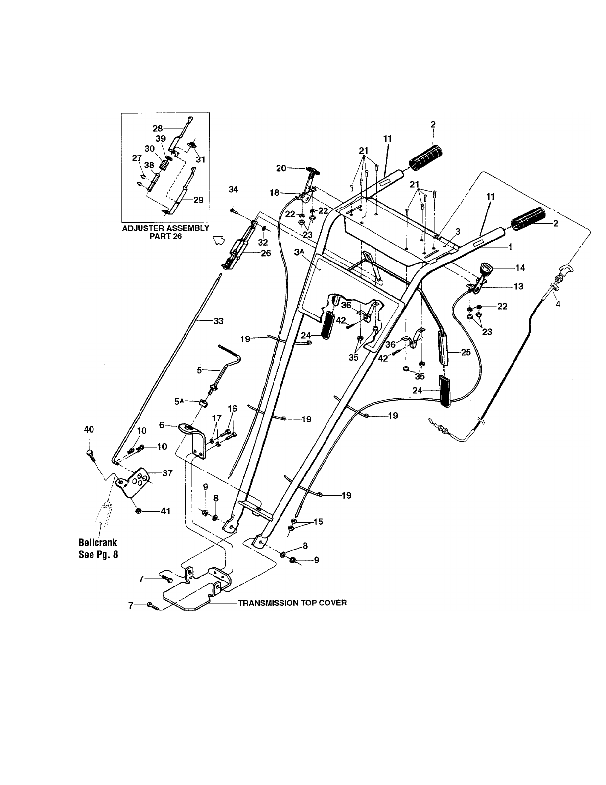
HANDLEBAR ASSEMBLY & CONTROL LEVERS
Page 3

MODELS 12197 & 12203 BOLENS® 6HP TILLER
HANDLEBAR ASSEMBLY & CONTROL LEVERS
REF
No.
1
2 9126 Grip-handlebars
3 1917210
3A 1917208
4 1916784 Reverse Clutch Control Cable
5 20703
5A 9955 Washer-keyed...........................
6 1900475001
7
8 9904
9
10 9338
11 1903597
13
14 9057 Knob-wheel gear control lever....
15
16
17 1100243 Lockwasher-3/8
18 1916900
19 1735531
20 9212
PART
No.
1917235
1100046
9837 Locknut-hex, 3/8-16
9442 Wheel Gear Control & Cable
1186211 Nut-hex, 5/16-24, wheel gear
1100068
DESCRIPTION QTY.
Handlebars-(incl. Ref. No.’s 2, 21 1114748 Screw-round hd, No. 10-32 x 1/2.
3 and 3A)
Decal-for operator control panel.. 1
Decal- model name, logo
Handle, Height Adjustment....... . 1 26 20862 Adjuster Assembly (incl. Ref. No.’s
Bracket-handlebar height adjust.. 1 27 9532 Klip Ring
Screw-hex hd., 3/8-16 x 1
Washer-plain (flat) 3/8, S.A.E
Hair Pin Cotter
Decal-forward clutch (A)
Assy. (incl. Ref. No.’s 14,15, 34 97083 Pin-Clevis
19, 21,22, and 23)
cable adjustment
Screw-hex hd., 3/8-16 x 3/4*
Engine Throttle Control & Cable... 2
Ties-plastic
Knob-throttle control lever
...............................
........................
.........
.......
..................
..........................
...........
.................
...................
........................
................................
........
..
...
....
REF
No.
. 1
. 2
. 1
. 1
. 1
. 2 28
. 2 29 20809 Adjuster, Left Side
. 2 30 9059 Spring-Adjuster
. 2
. 2 32 9386 Klip Ring
. 1
. 1 36 20806
. 2 38 9432 Bushing.......................................
. 2
. 2
. 4 42
. 1
22 1100240 Lockwasher-No. 10
23 1186208 Nut-hex, No. 10-32
24
25 20863
31
33 20831
35 9853 Sems Nut
37
39 9973 Washer........................................ 1
40 1100805 Screw-hex hd., 1/4-20 x 3/4*
41
PART
No. DESCRIPTION QTY
....................
.....................
9390
20808 Adjuster, Right Side
9522
20888 Swivel
9811 Nut-1/4-20................................... 1
9552
Grip-paddle................................. 2
Bail-forward clutch control (incl.
two Grips, Ref. No. 24)
27, 28, 29, 30, 38 and 39)
.....................................
...........................
Nut-rectangular........................... 1
.....................................
Rod-forward clutch
...................................
....................................
Bracket-bail support
.........................................
Screw-flanged hex hd, self-
tapping, 1/4-20 x 1/2*
............
.......
....................
......................
.....................
...................
......
..............
8
4
4
1
1
2
1
1
1
1
1
1
4
2
1
1
1
2
Specify GRADE 5 if ordering part locally.
(A) Model 12197
(B) Model 12203
Page 4
BOLENS® 6HP TILLER
MODELS 12197 & 12203
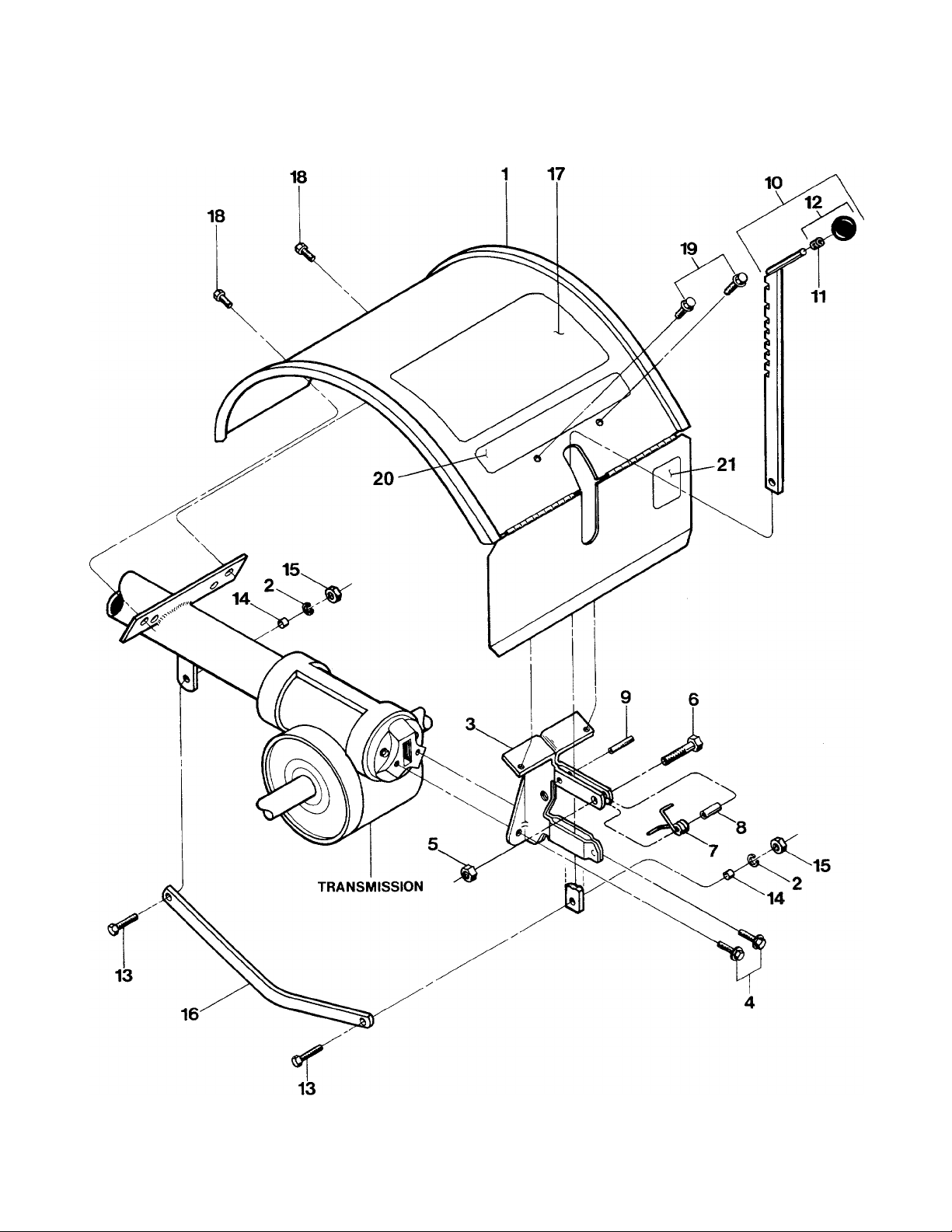
HOOD, BRACKET & DEPTH REGULATOR
Page 5

MODELS 12197 & 12203 BOLENS® 6HP TILLER
HOOD, BRACKET & DEPTH REGULATOR
REF
No.
4 90038 Screw-flanged hex hd.. 1/4-20x1/2*
5 9811 Locknut-hex, 1/4-20
6 1100069
7
8 9438
9 9308 Roll Pin-1/4x 1 (spiral)
10
11 9120
12 9119
13 1100043
14 1113-1
PART
No. DESCRIPTION
1 1917236 Hood-tine cover, with hinged fiap. 15 1186231 Nut-hex, 3/8-16
incl. Ref. No. 17, 20, 21. (B)
1
1917239
2 1100243 Lockwasher-3/8..........................
2527 Bracket-hood & depth regulator 5/16-18x1/2*............................ 2
3
9384 Spring-depth regulator plunger.... 1 [Not shown.]............................
1117A Bar Assembly-depth adjustment 24 1916419
Hood-tine cover, with hinged flap. 17 1916805 Decal-tiller operating instructions.
Incl. Ref. No. 21 - 27. (A)
(Incl. Ref. No. 9)
5/16-18x5/8*...........................
Screw-hex hd., 1/4-20 x 1 *
Spacer
........................................
(Incl. Ref. No’s, 11 and 12)
Ring-retaining, toierance ring
Knob-depth regulator
(Incl. Ref. No. 11)
Screw-hex hd, 3/8-16 x 1-1/4*
Bushing-spacer, drag bar
....................
...................
...............
...................
..........
QTY.
...
.......
.....
....
...
REF
No.
1
16 20775 Drag Bar-depth regulator
2
18 9553 Screw-hex hd, self-tapping.
1
19
2 20
1
21 1911361 Decal-Tine Warning. (B)
1 22 1916417
1 23 1916418 Decal-Thrown Object. (A)
1
1
1
25 1916420 Decal-Read Operator Manual before
1
26 1916421 Decai-Belt. (A) [Not Shown.]
2 27 1916423 Decal-Tines. (A) [Not Shown.].... 1
2
PART
No. DESCRIPTION QTY.
(B)
...........................................
9552
1917199 Decal-Logo. (A and B)
Screw-flanged hex hd, self-tapping.
Decal-Read Operator Manual. (A)
[Not shown.]............................ 1
Decal-Hot Surface. (A)
[Not shown.]............................ 1
Maintenance. (A) [Not Shown.] 1
..........................
...........
.............................
...............
............
......
2
1
1
2
1
1
1
1
Specify GRADE 5 if ordering part locally.
(A) Model 12197
(B) Model 12203
Page 6
BOLENS® 6HP TILLER
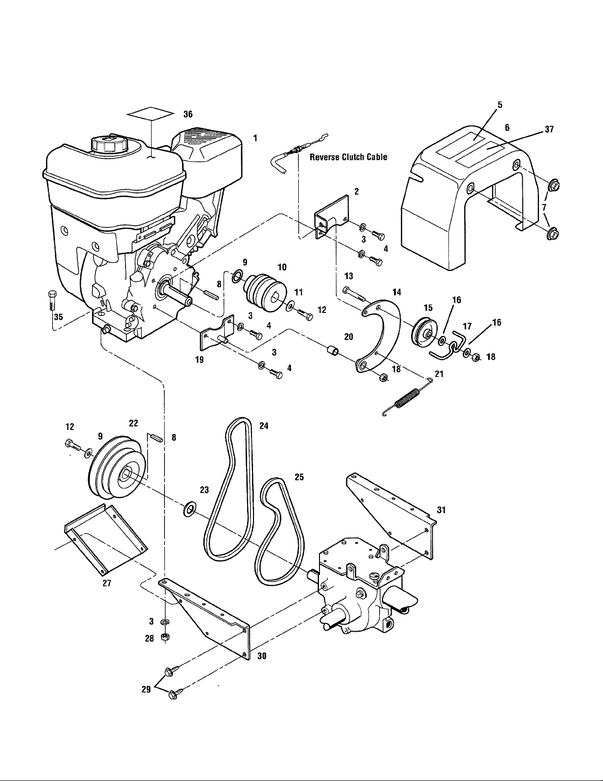
ENGINE, SUPPORT BRACKETS, PULLEYS, BELTS & BELT COVER
MODELS 12197 & 12203
26
Page 7

MODELS 12197 & 12203
ENGINE, SUPPORT BRACKETS, PULLEYS, BELTS & BELT COVER
BOLENS® 6HP TILLER
REF
No.
10
11
12
13
14
15
16
17
18
19
20 1916536
PART
No.
1
2
3
4
5
6
7
8
9
* *
1916633001
1100242
1111696
1904557
1917139
1186391 Nut-5/16-18, Flange Lock
1108841
1138-1
1916520
9944
9572
1111606
1916578001
1916535
1107382
1916725
1110107 Locknut, 5/16-18
1916559001
DESCRIPTION
Engine-6HP,
standard recoil start
Bracket, Clutch Cable
Lockwasher-5/16
Screw-hex hd., 5/16-24 x 1/2
Decal-Hot surfaces/belt warning.
Cover-(incl. Ref. No. 5)
Key-3/16x 1-1/2.........................
Washer-Disc Spring
Pulley, Engine Drive
Washer, Belleville......................
Screw-hex hd., 5/16-24 x 1 -1/8..
Screw-hex hd., 5/16-18 x 2
Reverse Idler Arm
Pulley, Reverse Idler.................
Washer, Flat, 5/16.....................
Belt Guide
Bracket, Reverse Idler
Bushing
.....................................
...............
...............
......................
....
.............
.........
..................
.................
.......
.....................
.................................
.......................
..............
REF
QTY.
. 1
No.
21 1916728
1 22
1 23
8 24 1916753
4
25
1
26
1 self-tapping
2 27 1916189001
2 28
1
29
1
2 30
2
31
1 32
1 33
1 34
2 35
36
1 37
1
1
PART
No.
1916522
1440 Support Washer
1909404 Forward Drive Belt
1900396
1186230 Hex Nut, 5/16-18
1186329 Screw-flanged hex hd.,
1916797001 Support Bracket-engine, left side.
1916796001
....
....
....
1100799
1915810
1903584 Decal-Warning Hot Surface. (B)..
DESCRIPTION
Spring, Reverse Return
Pulley, Transmission.................. 1
Reverse Drive Beit
Screw-hex hd., #10-32 x 1/2,
Guard, Belts/Pulleys
5/16-18x3/4*............................
Support Bracket-engine, right side 1
Ref. No. not used.
Ref. No. not used.
Ref. No. not used.
Screw-hex hd., 5/16-18 x 1-1/2... 4
Decal-Stabilization
.............
.........................
.....................
.....................
.............................
..................
........................
.....................
QTY.
1
1
1
1
4
1
4
4
1
1
1
Specify GRADE 5 if ordering part locally.
* * See your local authorized engine service dealer for engine
parts or service. Refer to engine nameplate for engine type
and code information.
(A) Model 12197
(B) Model 12203
Page 8

BOLENS® 6HP TILLER
MODELS 12197 & 12203
FORWARD IDLER ASSEMBLY
REF
No.
1 1110108 Locknut-hex, 3/8-16
2
3
4 1916192001 Idler Arm-left, forward tiller
5 9338
6 20545 Washer-plain, 5/16
7 1111607 Screw-hex hd., 5/16-18 x 2-1/4*.
8
9 9479 Pivot Bushing
10 9340 Pin
PART
No. DESCRIPTION
..................
9090
20532 Spacer....................................... 1 13
1916727 Spring........................................
Specify GRADE 5 if ordering part locally.
Pulley-idler, forward tiller
direction
Hairpin Cotter
.............................................
.................................
............................
.........
..........
....................
...................
REF
QTY.
No.
11 20517-01 Forward Link
2
1 12 1916194001
14 1186230
1 15
1 16 20553
1 17
2 18 1916196001
1
19
2 20 1186331
1
21
PART
No.
1100242 Lockwasher-5/16......................
1916195001
20532
1100043
1917149001
DESCRIPTION QTY
............................
Mounting Bar
I\lut-hex, 5/16-18
Shifting Base
Spacer-Bushing........................ . 2
Bushing-bellcrank
Bellcrank
Screw-hex hd., 3/8-16x1-1/4*..
Screw-flanged hex hd..
5/16-18x1
Belt Guide-forward belt
............................
......................
............................
....................
..................................
..............................
............
. 1
. 2
. 2
. 2
. 1
. 2
1
1
1
1
Page 9

MODELS 12197 & 12203
WHEEL SHAFT, ECCENTRIC SHAFT & TILLER SHAFT ASSEMBLIES
BOLENS® 6HP TILLER
16
WHEEL SHAFT, ECCENTRIC SHAFT & TILLER SHAFT ASSEMBLIES
REF
No.
1
2 9511
3 1166-1
—
—
—
4
5
6
7 20914
8
PART
No.
9621
DESCRIPTION
Oii Seal-left and right sides
Ring-retaining, heavy-duty, external 2
Shim-1-1/64I.D., .062 thick
1166-2
1166-3
1166-4
1086
2494
9373
Shim-as above, but .030 thick....
Shim-as above, but .015 thick.... A/R 12 9055 Spring.......................................
Shim-as above, but .010 thick....
Bushing.....................................
Wheel Shaft (axle)-incl. Ref. l\lo. 6
Key-hi-pro (1/4 X1-5/16), clutch
to wheel shaft
........................
Gear-wheel drive (worm gear). 18
9935
cast iron
Shim-between key and gear 19
.................................
(1.016I.D.X1.468 0.D.X.062
thick)
......................................
Specify GRADE 5 if ordering part locally.
PART
No.
20712 Clutch-wheei drive, cast iron
......
QTY.
2
REF
No.
9
10 20879 Eccentric Shaft-wheel clutch
.......
A/R
shifting
A/R 11 1442 Pin-eccentric shaft
A/R
2 14 20757
1
9622 Oil Seal-eccentric shaft............ 1
13
Lever-eccentric shaft
11000804
15
16 97074
Screw-hex hd., 1/4-20 x 1/2*....
Ball Bearing-for tiller shaft
1 17 20896 Tiller Shaft-incl. Ref. No. 18
1104
Key-woodruff, 1/4 x 1-1/4,
1 for tiller shaft/worm gear
20913 Worm Gear-bronze, tiller drive... 1
1
A/R - As Required
DESCRIPTION
..................................
...................
...
...............
.......
.....
.......
QTY.
1
1
1
1
1
1
2
1
1
Page 10

BOLENS® 6HP TILLER
BOLO TINES, WHEELS
FRONT/
FORWARD
MODELS 12197 & 12203
BLUNT END TOWARDS YOU
LEFT HAND TINE RIGHT HAND TINE
10
FRONT/
FORWARD
Page 11

MODELS 12197 & 12203
BOLENS® 6HP TILLER
BOLO TINES, WHEELS
REF PART
No.
1
2 1270-2A Bolo Tine-single, right hand tine
3 1733398
5
7
8
No.
1100043
1982612
1270-1A Bolo Tine-single, left hand tine
1902154001
Screw-hex hd., 3/8-16 x 1-1/4*.... 16 1901118 Replacement set of 16 Bolo Tines-
used on left side of tiller (Incl.
two of each Ref. No.'s 1 and 3). 8 each of Ref. No.’s 1 and 3
Hex Locknut, 3/8-16................... 18 9
Screw-hex hd., 3/8-16 x 2, tire mounted on 6” gray wheel.
GRADE 8
used on right side of tiller (Incl. 10
two of each Ref. No.'s 1 and 3). 8 specs, as above
Tine Holder-for bolo tines, left 11 9380
and right sides
DESCRIPTION QTY. No. No.
................................
........................
REF
2
2
12 9338
PART
DESCRIPTION
includes eight each of right hand
and left hand tines, and sixteen
......
2706-01 Wheel & Tire Assy-left side, 4.10x6
tubeless pneumatic (10-20 lbs.
air required), tractor tread
2706-02 Wheel & Tire Assy-right side, same
......................
Clevis Pin-.312 X1 -3/4 long
Hitch Pin..................................... 2
.......
......
QTY.
1
1
1
2
CUSTOM TILLING TINES (EXTRA LONG-WEARING)
Special hard-faced tines that are thicker than standard tines for use in sandy, gritty soil, when custom tilling or market gardening
REF PART REF
No. No.
10802 Custom Tilling Tine Kit-(lncludes
8 #2475-1 bolo tines,
8 #2475-2 bolo tines, 16 #1100043
screws and 16 #1733398 locknuts) 1
IMPORTANT: Left and right sides of tiller are determined by
standing in the operator position and facing the direction of
forward travel.
* Specify GRADE 5 if ordering part locally.
DESCRIPTION QTY.
No. No.
PART
DESCRIPTION QTY.
2475-1 Bolo Tine, custom tilling, left hand 8
2475-2 Bolo Tine, custom tilling, right hand 8
11
Page 12

BOLENS® 6HP TILLER
TRANSMISSION HOUSING, COVERS, SEALS, GASKETS & PLUGS
MODELS 12197 & 12203
NOTE 1: THESE SCREWS ARE A SPECIAL SEALING SCREW THAT CAN NOT BE REUSED
WITHOUT RISKING THE LOSS OF TRANSMISSION OIL. IF THESE SCREWS ARE LOOSENED
OR REMOVED, THEY MUST BE REPLACED WITH NEW HARDWARE.
12
Page 13

MODELS 12197 & 12203
TRANSMISSION HOUSING, COVERS, SEALS, GASKETS & PLUGS
BOLENS® 6HP TILLER
REF
No.
1 9621
2 9726
3 97076
4
5 85030
6 11513
7 20694
10
11 97073
12 90038
* Specify GRADE 5 if ordering part locally.
A/R-As Required
PART
No.
1186329 Screw-flanged hex hd.,
8 1916197001
9467
9
1916198001 Plate-wheel drive cable mounting.
DESCRIPTION
Oil Seal-double lip, wheel shaft,
right and left sides...................
Plug-pipe, 1/4, oil level hole and
gear oil drain hole
Seal-transmission bore
5/16-18x3/4*
Oil Seal-input pinion shaft
Cover-top of transmission (incl.
four of Ref. No. 18 and two of
each of Ref. No.’s 21 and 22)....
Gasket-transmission top cover
Transmission case, tube and rear
housing assembly
Plug-gear oil fill hole...................
Oil Seal-tiller shaft, left and right 22 1100068
sides........................................
Screw-flanged hex hd.,
5/16-18x5/8*............................
...........................
...................
..............
..........
...................
REF
QTY.
..
No.
13 1916273001
2 14 1129-1
2
15
1
6 16 1115
1 17 1124-2
18 1186331
1 5/16-18x1*..............................
1 19 1915087 Screw Kit; includes five (5)
1 screws
1 20 This Ref. No. not used
1 21 1100243 Lockwasher-3/8.........................
2
2
PART
No.
1915089 Screw Kit: includes three (3)
DESCRIPTION QTY.
Cover-tiller housing, left side..... 1
Gasket-tiller housing cover, .010
(fits all covers)
1/4-20 X 7/8 self-sealing ....
screws
..............................
Cap-rear bearing
Gasket-rear bearing cap, .010
thick
........................................
Screw-flanged hex hd.,
1/4-20x5/8 self-sealing
....................................
Screw-hex hd., 3/8-16 x 3/4*..... 2
.................
.......................
A/R
A/R
1
A/R
4
A/R
2
13
Page 14

BOLENS® 6HP TILLER
MODELS 12197 & 12203
DRIVE SHAFT, INPUT PINION SHAFT & GEAR ASSEMBLIES
MAIN DRIVE SHAFT ASSEMBLY
14
INPUT PINION SHAFT &
GEAR ASSEMBLY
Page 15

MODELS 12197 & 12203
MAINE DRIVE SHAFT, INPUT PINION SHAFT & GEAR ASSEMBLIES
BOLENS® 6HP TILLER
REF
PART
No.
1 1714
2 20718
3 9301
4 11603
1224-1
5
5 1224-2
5 1224-3
1325C
No.
DESCRIPTION QTY.
MAIN DRIVE SHAFT
Bearing-tapered roller with race.. 1
Gear-spur, main drive shaft
Key-3/16 sq. X1
Drive Shaft-main drive shaft is one-
piece with integral, single-lead
work-hardened worm at front to 9
drive the wheel worm gear, and
integral six-lead work-hardened
worm at rear to drive the tiller
gear (also includes pressed-on
#1714 rear roller bearing, race
for bearing and #9301 key)
Shim-rear bearing cap, .010 thick
(see Note 1 below)
Shim-same as above, but .030 thick 18
(see Note 1)
Shim-same as above, but .005 thick
(see Note 1)
Shim Set-includes the following
shims: two 1224-1; two 1224-2;
one #1224-3
........................
..........................
..........................
.........................
......
...
................
1
1
1
A/R
A/R
A/R
A/R
REF
No.
PART
No.
DESCRIPTION QTY.
INPUT PINIDN SHAFT & GEAR ASSEMBLY
9572 Screw-hex hd.,
6
5/16-24x1-1/8*
9944 Washer-disc spring (concave
7
surface faces pulley)
8 1108841
20880
10 1440
11
85030
12 9500 Ring-retaining (snap ring), externa
13 9953 Washer-thrust
14
9428
9677 Set Screw-5/16-18x3/8*............
15
16 20791 Input Pinion-steel shaft
17 20792 Gear-input pinion
9093 Retainer-snap ring, external
19 20799
9517 Retainer-snap ring, internal
20
Key-3/16 sq.x 1-1/2
Pulley-transmission drive
Washer-support
Oil Seal-input pinion shaft, front.
Bushing.....................................
Pinion Assy-(incl. one each of Ref.
No.’s 16,17 and 18)
.......................
.............
..................
.........
........................
...........................
.............
......................
.....
...............
......
1
1
1
1
1
1
1
2
1
1
1
1
1
A/R
1
NOTE 1-Shim between drive shaft rear bearing and rear bearing cap to achieve 5-to-10 thousandths of an inch (.005-.010) end
play on drive shaft.
A/R - As Required
* Specify GRADE 5 if ordering part locally.
15
Page 16

BOLENS® 6HP TILLER MODELS 12197 & 12203
HiLLER/FURROWER ATTACHMENT
11
16
Page 17

MODELS 12197 & 12203
BOLENS® 6HP TILLER
HILLER/FURROWER ATTACHMENT
REF
No.
1 1900771001 Furrower-blade only
2 1186098 Carriage Bolt-5/16-18x3/4............. 4
3 1177548 Star Washer-external tooth, 5/16 4
4 9902 Plain Washer-5/16 S.A.E
5 9824 Wingl\lut-5/16-18
6 1900773001 Hiller Wing-left
7 1900774001 Hiller Wing-right
8 1900772001 Bracket-blade mounting
PART
No.
DESCRIPTION
.....................
..........
...........................
..............................
............................
............
1
4
1
1
1
QTY.
4
REF
No.
9 9725 , Carriage Bolt-blade mounting,
10 1100243 Lockwasher-3/8, plated.............. 2
11 1186231 Nut-hex, 3/8-16, plated
12 9318 Pin-clinch....................................... 1
PART
No.
12579 Hiller/Furrower-complete attachment
DESCRIPTION
3/8-16x1-1/2
(owner must bolt blade to
mounting bracket, and wings to
blade). Instructions included.... 1
..............................
..................
2
2
QTY.
17
Page 18

BOLENS® 6HP TILLER
MODELS 12197 & 12203
ROW MARKER ATTACHMENT
BUMPER ATTACHMENT
PART #1904522001
18
BUMPER ATTACHMENT PART #12593
(Viewed from front of tiller)
Page 19

MODELS 12197 & 12203
BOLENS® 6HP TILLER
ROW MARKER ATTACHMENT & BUMPER ATTACHMENT
REF
No.
PART
No.
DESCRIPTION
Row Marker Attachment - Part #12589
1 1904522001 Main Support & Yoke Assy-
complete. Incl. Ref. No.'s
10,11,12,13,14,15,16,17 & 18. 1
2 1594 Marker Blade-blade only
3 1904524001 Marker Arm-main arm
4 1904523001 Marker Arm-extension arm with
stop pin
5 9347 Hitch Pin-(incl. in Hardware Pkg
#1837)....................................... 1
6 9786 Thumbscrew-1/4-20 x 1/2, not
avail, sep. (see hardware pkg.
#1837)
7 1596 Nut Bar-(inci. in hardware pkg
#1837)....................................... 1
8 9828 Nut-hex, 10-24 w/attached start
washers, not avail, sep. (see
hardware pkg #1837)
9 1100135 Screw-round hd.,10-24 X1, not
avail, sep. (see hardware pkg
#1837)
1837 Hardware Package-includes: one
#9347 hitch pin (Ref. 5), two
#9786 thumbscrews (Ref. 6),
one #1596 nut bar (Ref. 7),
two #9828 hex nuts (Ref. 8),
two 1100135screws (Ref. 9).... 1
12582 Row Marker Attachment & Pony
Hiller/Furrower Attachment -
complete: incl. #12579 Pony
Hiller/Furrower and #12589
Row Marker
12589 Row Marker Attachment -
complete: attaches to furrower
attachment #12579, includes
#1904522001 Main Supports
Yoke Assy................................. 1
.....................................
.......................................
.......................................
..............................
......
...........
..................
................
1
1
1
QTY.
2
2
2
1
REF
No.
PART
No.
DESCRIPTION
QTY.
Row Marker Main Support S Yoke Assembly - Part #1904522001
1186349 Screw-hex flanged locking,
10
3/8-16x1-1/2*
1593 Stop Bar
11
1592 Yoke
12
1591 Tube Key-square
13
1590 Washer-friction
14
1588 Main Support
15
1589 Washer-square hole
16
9925 Washer-disc spring
17
1186231 Nut-hex 3/8-16............................... 1
18
........................................
..............................................
............................
..........................
..............................
...............................
....................
.......................
1
1
1
1
2
1
1
1
Bumper Attachment - Part #12593
1904757001 Bumper-top section
19
1904758001 Bumper-bottom section
20
1731025 Bolt-curved head, 5/16-18x2
21
(special bolt); also see #1915811
hardware kit
1111608 Bolt-hex hd., 5/16-18 x 2-1/2*,
22
not avail, separately (order
#1915811 hardware kit
1100242 Lockwasher-5/16, not avail.
23
separately (order #1915811
hardware kit
1186230 Nut-hex, 5/16-18, not avail
24
separately (order #1915811
hardware kit
1915811 Hardware Kit: two #1731025
curved head bolts; four #1111608
hex hd. bolts; six #1100242 lockwashers; six #1186230 hex nuts 1
......................
.............
..............................
..........
..............................
.........
..............................
1
1
2
4
6
6
Note: Common hardware listed above as “not available sepa
rately” can be easily found at most good, local hardware
stores.
Specify GRADE 5 if ordering part locally.
19
Page 20

Parts Ordering Information
For service or parts for your unit or engine:
For service assistance or parts, contact your local authorized
dealer or call or write to the factory. When ordering parts, be
sure to provide the following;
• Serial number and model number of your unit.
• Part number of the part needed.
• Part description.
• Quantity needed.
For engine service or parts, contact your local authorized engine
dealer. Look In the Yellow Pages of the phone book under
“Engines-Gasoline” for the name of local authorized engine deal
ers. An authorized engine dealer can handle all parts, repairs,
and warranty service concerning the engine.
NOTE: Some parts on your engine are exclusive to this unit and
may not be available from the engine dealer. Refer to the engine
drawings in this catalog to identify and order these exclusive
parts.
Record your unit’s model number and serial number:
When requesting service or parts from the factory or your local
authorized dealer, be sure to provide the information on the
unit’s model/serial number decal. The location of this decal is
pointed out by the arrow in the illustration below.
Model Number:
___________________________________
CAUTION
We urge that you use only genuine replacement
parts, which meet all of the latest requirements.
Replacement parts manufactured by others
could present safety hazards, even though they
may fit on this product!
IMPORTANT:
All of our genuine replacement parts must conform to rigid
quality specifications. Some replacement parts we provide may
vary slightly in shape, color or texture from the original parts,
but these slight variations will not affect unit performance.
NOTE: LEFT and RIGHT sides of the unit are determined by
standing behind the handlebars and facing the direction of for
ward travel.
Serial Number:
Customer Service; 1-800-437-8686 »Technical Service: 1-800-520-5520 • Parts Service: 1-800-648-6776
Customer Service: (518) 391 -7007 • Technical Service: (518) 391 -7008 • Parts Service: (518) 391 -7006
For customer assistance, contact your nearest authorized dealer or:
GARDEN WAY INCORPORATED • 1 Garden Way • Troy, New York 12180
•FAX; (518) 391-7332
Outside the United States and Canada:
•FAX (518) 391-7332
1905307 (1/99) Printed in U.S.A.
©1999 Garden Way Incorporated
 Loading...