

Bolens 11A-020W765 Fast Start Manual
WARNING: Read and understand all instruction,
Hex Screw
Shoulder
Screw
warning, and danger labels.
Para instrucciones en Español, refiérase al Manual
del Operador.
Tools Required
• ⁄-inch wrench (or adjustable wrench)
• ⁄-inch wrench (or adjustable wrench)
• ⁄-inch wrench (or adjustable wrench)
• ⁄-inch wrench (or adjustable wrench)
• Flat-head screwdriver
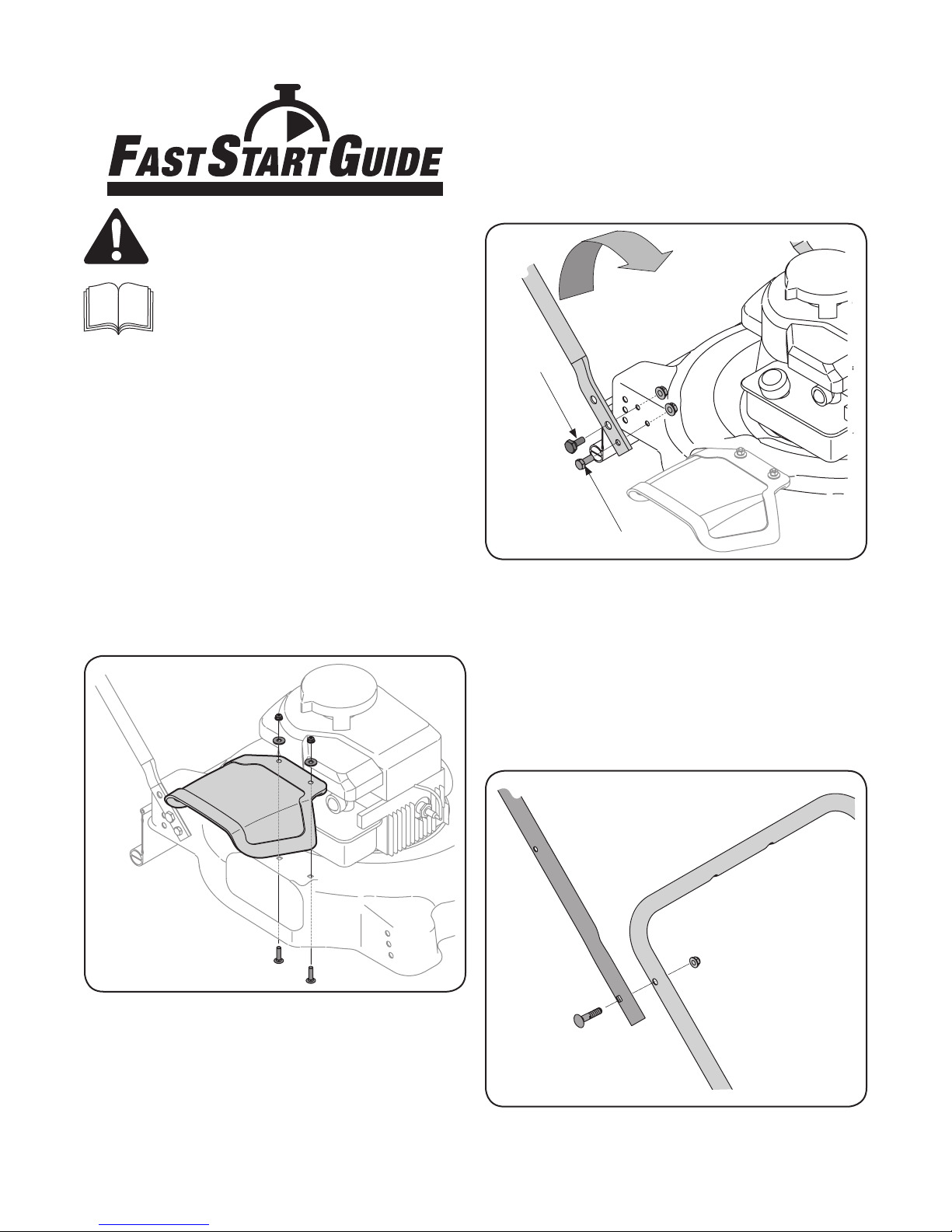
Chute Deflector Assembly
NOTE: Use the hardware in Group 1 to complete the following
steps. Refer to your Operator’s Manual.
1. Align the holes on the chute deflector with the
corresponding holes on the deck surface.
2. Insert carriage screws up through the underside of the
deck and through the chute deflector. See Figure 3-1.
1. Lift the rear of the deck and place it on a block of wood to
secure it.
2. Place the lower handle over the deck and align the holes on
the deck with the corresponding holes on the handle.
3. Pivot the lower handle forward and secure it to the deck
using the hex screws, shoulder screws, and flange lock
nuts. See Figure 3-2.
Figure 3-2
Upper Handle Assembly
NOTE: Use the hardware in Groups 2 and 4 to complete the
following steps. Refer to your Operator’s Manual.
1. Place the upper handle in position over the lower handle
keeping the blade control handle facing up.
2. Secure the upper handle to the lower handle using the
carriage bolts and lock nuts from Group 4 of the hardware
pack. See Figure 3-3.
3. Secure each screw with a washer and lock nut.
Figure 3-1
Lower Handle Assembly
NOTE: Use the hardware in Groups 2 and 4 to complete the
following steps.
Figure 3-3
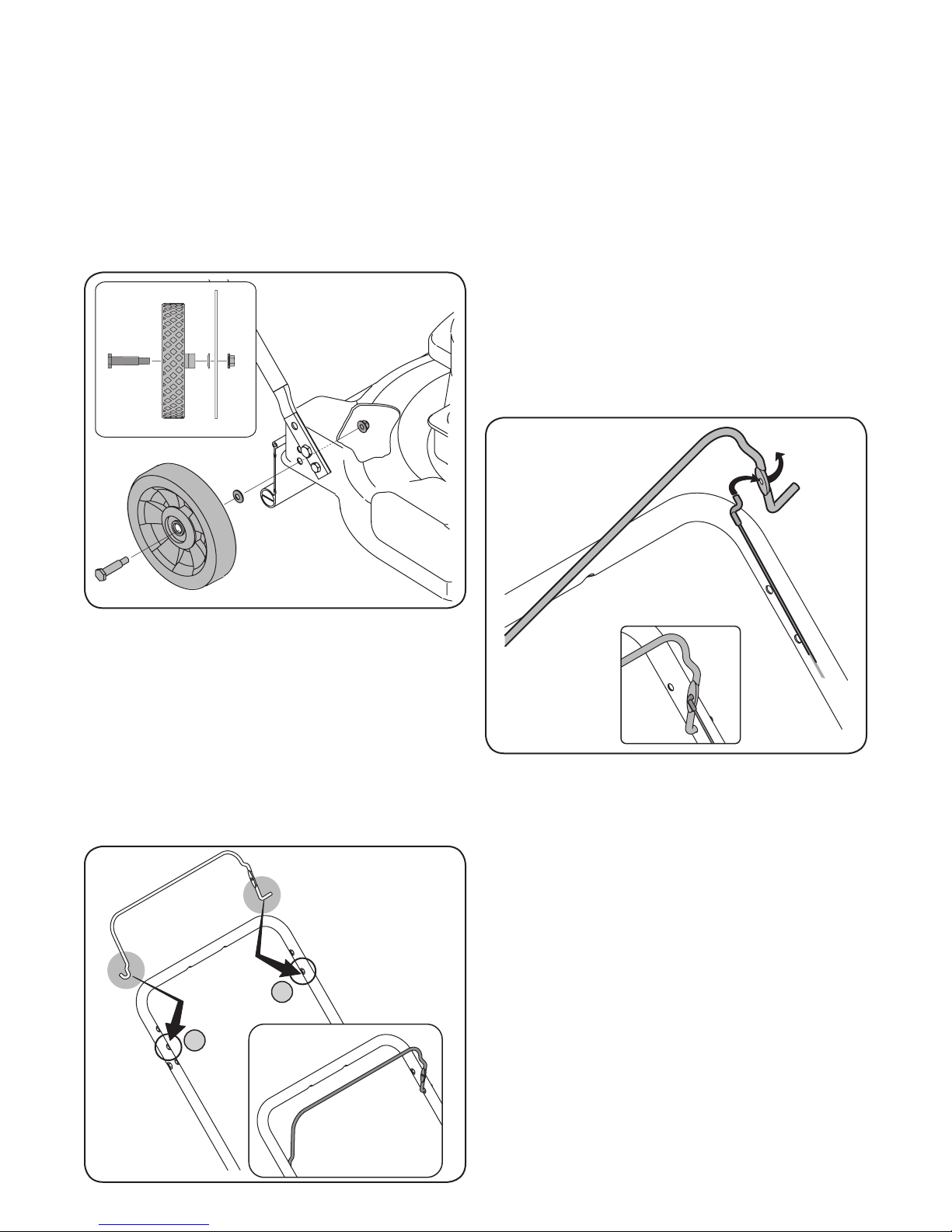
Wheels
1
2
NOTE: Use the hardware in Group 3 to complete the following
steps. Refer to your Operator’s Manual.
The holes in the deck provide three cutting heights. Use
corresponding holes when attaching all four wheels (i.e. for the
lowest cutting position, assemble each wheel at the highest hole
on the deck). Refer to the Cutting Height Adjustment section for
more information.
1. Secure each wheel to the deck as shown in Figure 3-4.
2. Gently squeeze the blade control inward and insert the
straight end into the lower hole located on the left side of
the upper handle. See Figure 3-5.
3. Check to confirm that the blade control pivots freely
against the upper handle.
NOTE: Your mower has been supplied with one of two types of
control cables - one that is secured with a snap fitting as shown
in Figure 3-7 or one that is secured with a stud as shown in Fig.3-
8. Make note of the cable supplied with your mower and follow
the appropriate steps below.
Control Cable (Snap Fitting)
Unwrap the control cable from the engine and route it under the
lower handle.
Z Fitting
1. To make it easier to attach the Z fitting, temporarily remove
the left side of the blade control as shown in Figure 3-6.
Figure 3-4
NOTE: The cupped side of each washer should be pressed
against the deck.
Blade Control
NOTE: If the blade control is secured and in place on the upper
handle, you may skip the following three steps. If, however, the
blade control became displaced either during shipping or during
assembly, reattach it as follows:
1. Insert the curved end of the blade control into the center
hole located on the right side of the upper handle. See
Figure 3-5.
Figure 3-6
2. Hook the Z end of the brake cable into the control from the
inside to outside. See Figure 3-6.
3. Reattach the left side of the blade control.
Figure 3-5
 Loading...