

Page 1

TEN CENTS
ASSEMBLY
OPERATION
MAINTENANCE
PARTS LIST
Important:
Read Safety Rules and
Instructions Carefully
Model Nos.
117-030A
117-030-300
PRINTED IN U.S.A.
FORM NO. 770-6809
Page 2

IMPORTANT
It is suggested that this manual be read in its entirety before attempting to assemble or operate. Keep this
manual in a safe place for future reference and for ordering replacement parts.
This unit is shipped WITHOUT GASOLINE of OIL. After assembly, see operating section of this manual for
proper fuel and amount.
Your rotary mower is a precision piece of power equipment, not a plaything. Therefore exercise extreme
caution at all times.
SAFE OPERATION PRACTICES FOR WALK-BEHIND MOWERS
TRAINING
1. Read the Operating and Service Owner’s
Manual carefully. Be thoroughly familiar with
the controls and the proper use of the equip
ment.
2. Never allow children to operate a power
mower. Only persons well acquainted with
these rules of safe operation should be
allowed to use your mower.
3. Keep the area of operation clear of all per
sons, particularly small children and pets.
Stop engine when they are in the vicinity of
your mower. Although the area of operation
should be completely cleared of foreign
objects, a small object may have been over
looked and could be accidently thrown by the
mower in any direction.
PREPARATION
1. Thoroughly inspect the area where the equip
ment is to be used and remove all stones,
sticks, wire, bones and other foreign objects
which could be picked up and thrown by the
mower in any direction.
2. Do not operate equipment when barefoot or
wearing open sandals. Always wear substan
tial footwear.
3. Do not wear loose fitting clothing that could
get caught on the mower.
4. Check the fuel before starting the engine. Do
not fill the gasoline tank indoors, when the
engine is running, or while the engine is still
hot. Wipe off any spilled gasoline before
starting the engine.
5. Disengage the self-propelled mechanism or
drive clutch on units so equipped before
starting the engine.
6. Never attempt to make a wheel or cutting
height adjustment while the engine is
running.
7. Mow only in daylight or in good artificial
light.
8. Never operate the equipment in wet grass.
Always be sure of your footing; keep a firm
hold on the handle and walk, never run.
OPERATION
1. Do not change the engine governor settings or
overspeed the engine. Excessive engine
speeds are dangerous.
2. Do not put hands or feet near or under
rotating parts. Keep clear of the discharge
opening at all times.
3. Stop the blade(s) when crossing gravel drive,
walks or roads.
4. After striking a foreign object, stop the
engine, remove the wire from the spark plug.
2 equipment specifications.
thoroughly inspect the mower for any
damage, and repair the damage before restart
ing and operating the mower.
5. If the equipment should start to vibrate abnor
mally, stop the engine and check immediately
for the cause. Vibration is generally a warning
of trouble.
6. Stop the engine whenever you leave the
mower, before cleaning the mower housing,
and when making any repairs or inspections.
7. When cleaning, repairing or inspecting, make
certain the blade and all moving parts have
stopped. Disconnect the spark plug wire, and
keep the wire away from the plug to prevent
accidental starting.
8. Before attempting to unclog the mower or
discharge chute, stop the engine and be sure
the blade(s) have stopped completely. Dis
connect the spark plug wire and keep the wire
away from the plug to prevent accidental
starting.
9. Do not run the engine indoors.
10. Shut the engine off and wait until the blade
comes to a complete stop before removing
the grass catcher.
11. Mow across the face of slopes, never up-anddown. Exercise extreme caution when chang
ing direction on slopes. Do not mow
excessively steep slopes.
12. Always disconnect electric mowers (line
operated) before cleaning, repairing or
adjusting.
13. Never operate mower without proper guards,
plates or other safety protective devices in
place.
14. Keep washout ports and other mower
housing service openings closed when
mowing.
MAINTENANCE AND STORAGE
1. Check the blade and engine mounting bolts at
frequent intervals for proper tightness.
2. Keep all nuts, bolts, and screws tight to be
sure the equipment is in safe working condi
tion.
3. Never store the equipment with gasoline in
the tank inside of a building where fumes may
reach an open flame or spark. Allow the en
gine to cool before storing in any enclosure.
4. To reduce fire hazard, keep the engine free of
grass, leaves, or excessive grease.
5. Check the grass catcher bag frequently for
wear or deterioration. For safety protection
replace only with new bag meeting original
Page 3
ASSEMBLY
Your new mower is shipped completely assem
bled with the exception of the handle.
1. Remove lawn mower and all parts from
carton. Make certain that all loose parts and
literature are removed from carton before
carton is discarded.
2. Extend throttle control assembly, which is
attached to rear of mower and place on floor.
^CAUTION
Do not bend or kink control wire.
NOTE
Some engines have manual friction
control on the engine; these require
no remote throttle control.
3. a. Snap lower handle into position on two
lugs which extend from either side on the
rear of the deck.
b. Assemble the two upper handle parts with
cap screws and locknuts provided in parts
bag. The yellow cap screw should be used
to attach throttle control assembly to
upper handle as shown in diagram. Do not
tighten nuts.
c. Attach upper handle assembly to lower
handle with cap screws and locknuts.
Tighten all nuts.
d. Secure control wire to lower handle with
cable clips.
4. Check all nuts and bolts for correct tightness.
5. Slip hand grips on the upper end of each
handle. They will slip on more easily PF you
first soak them in warm soapy water.
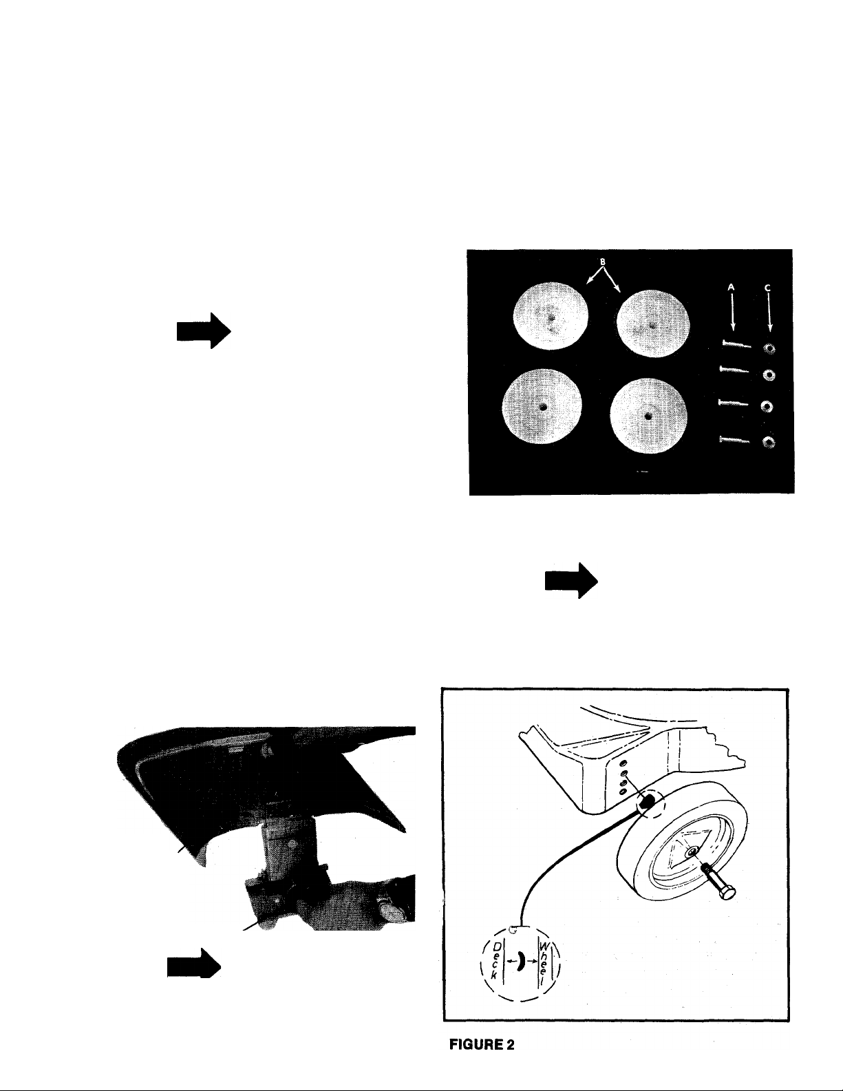
6. Place shoulder bolt (A) through wheel (B). See
figure 1.
7. Place crown side of belleville washer (c)
towards the wheel (away from deck). See
figure 2.
8. Using a W wrench secure wheel to deck.
FIGURE 1
NOTE
Tighten shoulder bolt enough to
slightly compress the belleville
washer.
DO NOT COMPLETELY compress
washer.
Chute Deflector
Shipping Block to be Removed
NOTE
It may be necessary to bend the
ends of the lower handle inward
slightly to assure a snug fit against
the deck mounting area.
Page 4

____
^CAUTION
Pleast note that the chute deflector
on your mower is in an upright posi
tion. It is heid in that position by a
shipping block. This block is used
for shipping purposes only. It must
be removed and discarded before
your mower is put into operation.
OPERATION
NOTE
For shipping purposes your mower
is set with the wheels in a low cut
ting height position. For best re
sults, raise the cutting position untii
it is determined which height is best
for your lawn. See adjustments.
1. Service engine with gas and oii. See engine
manual packed with lawn mower for complete
instructions for the care and maintenance of
engine. READ DIRECTIONS CAREFULLY.
2. When ready to start engine, place throttle
control lever in “START” position and start
engine in accordance with instructions in
engine manual. After engine starts, move
throttle control lever to desired engine speed.
The engine is stopped by placing control lever
in the “STOP” position.
3. Be sure that lawn is clear of stones, sticks,
wire or other objects which could damage
lawn mower or engine. For best results and
to insure more even grass distribution, do not
mow when lawn is excessively wet.
ADJUSTMENTS
CAUTION
A
Do not at any time make any adjust
ment to lawn mower without first
stopping engine and disconnecting
spark plug wire.
STANDARD CUTTING HEIGHT
Adjustment may be made by removing and
moving wheel studs to desired position. Cutting
heights will be raised as wheel studs are moved to
a lower hole and lowered as wheel studs are
moved to a higher hole in the deck. All wheel
studs must be mounted In a relative position to
the deck.
REMOTE THROTTLE (OPTIONAL)
If adjustment becomes necessary, the throttle
control wire assembly can be reset as follows:
1. Loosen, but do not remove, screw securing
throttle control wire assembly at engine.
Move throttle control lever on handle to
2.
“FAST” position.
Move lever, to which control wire is fastened
3.
at engine, to full open position and retighten
screw to secure throttle control wire
assembly.
LUBRICATION
IMPORTANT
Always stop engine and disconnect
spark plug wire before cleaning, lu
bricating or doing any kind of work
on lawn mower.
Wheels—Wheel bearings require no lubrication.
Throttle (Optional)—Periodically lubricate throttle
control lever and throttle wire assembly with a few
drops of light oil (SAE No. 10 or 20) for ease of
operation.
Protective Shield—The pivot points on the
protective shield should be lubricated periodically
with light oil to prevent any rust or binding up.
Always disconnect
spark plug cable dur
ing repairs, refueling
or changing oil. En
gine oil may be
drained through oil
filler opening by tilt
ing the mower on its
side. Change oil after
first 5 hours of opera
tion while engine is
warm. Thereafter,
change oil every 25
hours of operation
while engine is warm.
Chute Deflector—The torsion spring and pivot
point should be lubricated periodically with light
oil to prevent any rust or binding up. Deflector
should work freely.
NOTE: FILL AND
DRAIN OIL FROM OIL
FILL PLUG.
Page 5

MAINTENANCE
Cutting Blade—The blade may easily be removed
for grinding or replacement as follows :
1. Remove bolt and lockwasher holding blade
and blade adapter to engine crankshaft.
2. Remove blade and blade adapter from engine
crankshaft.
3. Remove two bolts, lockwashers and nuts
holding blade to blade adapter (if necessary).
When sharpening blade, follow the original angle
of grind as a guide. It is extremeiy important that
each cutting edge receives an equai amount of
grinding to prevent an unbalanced blade. An
unbalanced blade will cause excessive vibration
when rotating at high speeds and may cause
damage to the mower. Upon reassembly, make
certain all parts are assembled properly and
tightened securely.
NOTE
To ipsure safe operation of your
unit, all nuts and bolts must be
checked periodically for correct
tightness.
Deck—The underside of the mower deck shouid
be cleaned after each period of use as grass
clippings, leaves, dirt and other matter wiil
accumulate. This accumulation of grass clip
pings, etc., is undesirable as it will invite rust and
corrosion and may cause an uneven discharge of
grass clippings at the next cutting.
The deck may be cleaned by tilting the mower
forward or on its side and scraping clean with a
suitable tool or by washing with a stream of water
from a garden hose.
____
^CAUTION
Do not direct the stream of water at
a hot engine, as damage to the en
gine may result.
A'
STORAGE
The following steps should be taken to prepare
lawn mower for storage:
1. Clean and lubricate mower thoroughly as
described in the preceding instructions.
2. Refer to engine manual for correct engine
storage instructions.
3. Coat mower’s cutting blade with chassis
grease to prevent rusting.
4. Place blocks under deck to raise tires clear of
floor.
5. Store mower in a dry, dean area.
USING YOUR ROTARY MOWER
For best results, do not cut wet grass because it
tends to stick to underside of the mower thus
preventing proper discharge of grass clippings. If
wet grass must be cut, reduce walking speed to
help distribute the clippings more effectively.
New grass should be treated as wet grass,
otherwise a normal walking speed is about the
right pace for efficient mowing. The best mowing
pattern is one that allows the clippings to
discharge towards the uncut part of the lawn. This
permits recutting of the clippings to further
pulverize them. When cutting high weeds, dis
charge towards cut portion, then recut at right
angles to first direction.
Lawn should be cut in the fall as long as there is
growth.
NOTE
The manufacturer DOES NOT rec
ommend the use of any accessory
on this Rotary Mower other than
those manufactured by MTD Prod
ucts Inc.
GRASS CATCHER Model No. 197-003A is
available as optional equipment for the mowers
shown in this manual.
\ WARNING {
1. The mower should not be oper
ated without the entire grass catcher
or chute deflector in place.
2. The mower should not be oper
ated without the protective shield on
the rear of the deck in place.
NOTE
Under normal usage bag material is
subject to wear and should be
checked periodically. Be sure any
replacement bag complies with the
mower manufacturer’s recommen
dations.
For replacement bags, use only factory authorized
replacement bag No. 764-0119.
IMPORTANT
After striking a foreign object, stop
the engine, remove wire from spark
plug. Thoroughly inspect the mower
for any damage, and repair the dam
age before restarting and operating
the mower.
Page 6

117-030A
IF YOU WRITE TO US ABOUT THIS ARTICLE
OR IF YOU ORDER REPLACEMENT PARTS AL
WAYS MENTION THIS MODEL & SERIAL NO
MODEL
Page 7

PARTS LIST FOR MODEL 117-030A
REF.
PART
NO.
NO.
1
2 710-0158
COLOR
CODE
Engine
Hex Hd. Cap Scr. 5/16-24 x
DESCRIPTION
IV4” Lg.*
3
11448
4 736-0119
5 712-0123
6 711-0555
7
712-0123
—452
Deck Ass’y. —Comp.
Spring L-Wash. 5/16” Scr.*
Hex Nut 5/16-24” Thd.*
Pivot Pin
Hex Nut 5/16-24 Thd.*
8 714-0365 #6 Hi-Pro Key 5/32x5/8”
Dia.
91010769
742-0122
Biade Adapter Kit
Biade19”
11 736-0217 Spring L-Wash. 3/8” Scr.
Heavy Duty
12 710-0459
Hex Hd. Cap Scr. 3/8-24 x
1 Vz” Lg.—Heat Treated
131410769
710-0117
Biade Adapter Kit
Hex Hd. Cap Scr. 5/16-24 x
1 ” Lg.—H eat Treated
732-0253
15
16 11680
—452
Torsion Spring
Chute Defiector Ass’y.
17 738-0213 Axle Bolt
18 710-0136 Hex Hd. Cap Scr. V4-20 x
1.75” Lg.*
734-0480
19
20 736-0105
Wheel Ass’y.—Comp.
Bell. Wash. 3/8” Scr.
21 726-0106 Push-on Flange Palnut
22
11130
714-0104 Hair Pin Cotter
23
24
07039
25
11191
—452 Adapter Plate
Lower Handle
—452
Protective Shield Ass’y.—
Comp.
26 710-0567
Hex Hd. Cap Scr. Va-ISx
.62” Lg.
27 712-0107
Hex Cent. L-Nut V4-20 Thd.
28 710-0106 Hex Hd. Cap Scr. V4-20 x
IV4” Lg.*
293009363
746-0145
Upper Handle
Cable Clip
31 712-0107 Hex Cent. L-Nut Vi-20 Thd.
32
11609
Throttle Control Ass’y.—
Comp.
07071
33
34
35
36
731-0344
07470
11598
Grip
Throttle Control—Cover
Throttle Control—Knob
Throttle Control—Brkt.
Ass’y.
37
746-0229
Conduit and Wire
46 710-0289 Hex Scr. V4-2OX .50” Lg.*
NEW
PART
*For faster service obtain standard nuts, bolts and washers locally. If these items cannot be obtained locally, order by part
number and size as shown on parts list.
(452—Radiant Tangerine) When ordering parts if color or finish is important, use color code shown at left. t(e.g. Radiant
Tangerine Finish—11907(452).)
The engine is not under warranty by the mower manufacturer. If repairs or service is needed on the
engine, please contact your nearest authorized engine service outlet. Check the “Yellow Pages” of
your telephone book under “Engines — Gasoline.”
Find It Fast
In The
Yellow Pages
Page 8

MRTS INFORMATION
POWER EQUIPMENT PARTS AND SERVICE
Parts and service for all MTD manufactured power
equipment are available through the authorized service
firms listed below. Ail orders should specify the model
number of your unit, parts numbers, description of parts
and the quantity of each part required.
ALABAMA BIRMINGHAM
Auto Elactrie & Carburotor Co...2625 4th Ave. S
ARKANSAS NORTH LITTLE ROCK
Sutton's Lown Mower Shop
Mity Mite Motors, Inc;
CALIFORNIA SAN BERNARDINO
Lawn Mower Supply Co
J.W. Jewett Co
Luttig & Severson
COLORADO DENVER
South Denver Lawn Equip
CONNECTICUT SUFFIELD
The Jones & Ramsey Co
FLORIDA JACKSONVILLE
Rodeo Distributors
Moz-AII of Florida, Inc
GEORGIA EAST POINT
East Point Cycle 8i Key
ILLINOIS LYONS
Keen Edge Co
INDIANA ELKHART
Ports 8i Soles Inc
IOWA DUBUQUE
Power Lawn & Gordon Equip. .2551 J.F. Kennedy ....52001
KANSAS WICHITA
Mixon, Inc
LOUISIANA NEW ORLEANS
Suhren Engine Co......................... 8330 Eorhort Blvd
MARYLAND TAKOMA PARK
Cantor Supply Co.......................6867 New Hampshire Ave. 20012
MASSACHUSETTS SPRINGFIELD
Morton B. Collins Co
MICHIGAN MOUNT CLEMENS
Power Equipment Dist
Lorenz Service Co..............
MINNESOTA MINNETONKA
Honce Distributing Inc....................11212 Woyzata Blvd. ..55343
MISSISSIPPI BILOXI
Biloxi Soles & Service, Inc. ....506 Caillovet St
MISSOURI KANSAS CITY
Automotive Equip. Service
Henzier, Inc
NEW YORK CARTHAGE
Gamble Dist., Inc
Kimbar's, Inc
.............................
........................
........................
..............................
..........................
.........'........... ...............
...................................
...........................
..................................
..........
FORT SMITH
....................
................
SAN FRANCISCO
SACRAMENTO
..............
CORAL GABLES
...................
.....................
..................
LANSING
ST. LOUIS
SYRACUSE
Rt. 4, Box 368 ................ 72117
2515 Towson Ave
25608 E. Baseline — 92410
981 Folsom St.
2030 28th St
............
527 West Evans
850 Thompsonvi He Rd. 06078
2403 Market St
365 Greco Ave
...........
2834 Church St
8615 Ogden Ave
2101 Industrial Pkwy. ..46514
3030 Mascot
300 Birnio Ave..................01107
36463 South Gratiot... 48043
..........
2500 S. Pennsylvania .. 48900
............
3117 Holmes St.
2015 Lomoy Ferry Rd. 63125
West End Ave
115 N. Geddas St
....................
............
.....
..........
...................
..............
............ 32206
................
..............
............
.................
...........
.......................
............
................
..........
35233
72901
94107
95818
80223
33146
30344
60534
67204
70118
39533
64109
13619
13204
BRIGGS & STRATTON, TECUMSEH AND PEERLESS
PARTS AND SERVICE
Briggs & Stratton, Tecumseh and Peerless parts anc
service should be handled by your nearest authorized
engine service firm. Check the yellow pages of your
telephone directory under the listing Engines _______________
Gasoline, Briggs & Stratton or Tecumseh Lauson -------------------
NORTH CAROLINA GREENSBORO
Dixie Soles Company
Smith Hordwora Co........................515 N. George St
OHIO WADSWORTH
Notional Central .............................687 Seville Rd
Bleckrie, Inc
Steba’s Mid'Stata Mower Supply Box 366
Sunshine Wholesale Tire Outlet Route 224
McClure Lawn 8t Garden Supply...1114 Lexington Ave. . 44903
OKLAHOMA MUSKOGEE
Victory Motors, Inc
Ado Auto Supply
OREGON PORTLAND
Kenton Supply Co
PENNSYLVANIA LANCASTER
Roub Supply Co............................ James & Mulberry Sts... 17604
Bluemont Co
TENNESSEE KNOXVILLE
Master Repair Service
Memphis Cycle & Supply Co
American Soles & Service, Inc.. 1922 Lynnbrook
TEXAS DALLAS
Morr Brothers, Inc
Bullard Supply Co
Catto & Putty, Inc........................... P.O. Box 2408
Woodson Sales Corp..................... 1702 N. Sylvonia
UTAH SALT LAKE CITY
A-1 Engine & Mower Co................ 437 E. 9th St...................84111
VERMONT BURLINGTON
Vermont Appliance Co
VIRGINIA RICHMOND
RBI Corp........................................ 963 Myers St.................. 23260
WASHINGTON SEATTLE
Bailey's Rebuild, Inc
WEST VIRGINIA CHARLESTON
Young's, Inc....................................233 Virginia St., E. ...25301
WISCONSIN APPLETON
Automotive Supply Co
...................................
.................................
....................
GOLDSBORO
CLEVELAND
CARROL
WILLARD
MANSFIELD
.........................
ADA
...........................
...........................
PITTSBURGH
.................
MEMPHIS
.........
.........................
HOUSTON
.........................
SAN ANTONIO
FORT WORTH
....................
.....................
...................
327 Battleground Ave.. 27402
............
27530
................
7900 Lorain Ave
..............................
............................
605 S. Cherokee
301 E. 12th St
8216 N. Denver Ave. . 97217
11125 Fronkstown Rd.. 15235
2423 Broadway, N.E. ..37917
421 Monroe Ave
423 E. Jefferson
2409 Commerce St
44 Lakeside Ave
1325 E. Madison St. ...98102
123 S. Linwood Ave. ..54911
.................
...............
..................
................
..............
...........
.............
..........
.............
.............
44281
44102
43112
44890
74401
74820
38103
38116
75 203
77003
78206
76111
05401
WARRANTY PARTS AND SERVICE POLICY
The purpose of warranty is to protect the customer from defects in workmanship and materials, defects which are NOT detected
at the time of manufacture. It does not provide for the unlimited ond unrestricted replacement of parts. Use and maintenance ore
the responsibility of the customer. The manufacturer cannot assume responsibility for conditions over which it hos no control.
Simply put, if it's the manufocturer's foult, it's the manufacturer's responsibility; if it's the customer’s fault, it’s the customer's
responsibility.
CLAIMS AGAINST THE MANUFACTURER’S
WARRANTY INCLUDES
1. Replacement of Missing Ports on new equipment. 1. Model Number of unit involved.
2. Replacement nf Defective Ports within the warranty period. 2. Dote unit was purchased or first put into service.
3. Rapoir of Defects within the worronty period. 3. Dote of failure.
MTD PRODUCTS INC
5389 WEST 130th STREET • P. 0. BOX 2741 CLEVELAND OHIO 44111
AH claims MUST be substantioted with the following
information:
4. Nature of failure.
 Loading...