

Page 1

Owner's Operating
Service Instruction
10*
Manual
ASSEMBLY
OPERATION
REPAIR PARTS
rrnrrrrrrrrrrrrryyyrrirrrrrinr^
Model No,
114-530A
For one year from date of purchase, MTD Products Inc will replace for the original purchaser, free
of charge, F.O.B. factory or authorized service firm, any part or parts found to be defective in material
or workmanship. All transportation charges on parts submitted for replacement under this warranty
must be paid by the purchaser. This warranty does not include replacement of parts which become
inoperative through misuse, excessive use, accident, neglect, improper maintenance or alterations by
unauthorized persons. This warranty does not include the engine, motor, battery, battery charger or any
component parts thereof. For service on these units, refer to the applicable manufacturer's warranty.
The above warranty will apply only to the original owner and will be effective only if the warranty
card has been properly processed. It will not apply where the unit has been used commercially.
Warranty service is available through your local authorized service dealer or distributor. UNDER
NO CIRCUMSTANCES WILL THE RETURN OF A COMPLETE UNIT BE ACCEPTED BY THE
FACTORY UNLESS PRIOR WRITTEN PERMISSION HAS BEEN EXTENDED.
MTD PRODUCTS INC
PRINTED IN U.S.A.
WARRANTY
iUUUUUUUL»J> «.g.MJJJLRJULOAAIUUULJULRJLLftJULJUUl.lttJl.t».» « » «J
5389 WEST 130th STREET • P. 0. BOX 2741 CLEVELAND OHIO 44111
FORM NO. 770-4892
Page 2

I
SAFE OPERATION PRACTICES FOR WALK-BEHIND MOWERS
TRAINING
1. Read the Operating and Service Instruction Man
ual carefully. Be thoroughly familiar with the con
trols and the proper use of the equipment.
2. Never allow children to operate a power mower.
3. Keep the area of operation clear of all persons,
particularly small children and pets.
PREPARATION
1. Thoroughly inspect the area where the equipment
is to be used and remove all stones, sticks, wire,
bones and other foreign objects.
2. Do not operate equipment when barefoot or
wearing open sandals. Always wear substantial
footwear.
3. Check the fuel before starting the engine. Do not
fill the gasoline tank indoors, when the engine is
running, or while the engine is still hot. Wipe ofF
any spilled gasoline before starting the engine.
4. Disengage the self-propelled mechanism or drive
clutch on units so equipped before starting the en
gine (motor).
5. Never attempt to make a wheel adjustment while
the engine (motor) is running.
6. Mow only in daylight or in good artificial light.
7. Never operate the equipment in wet grass. Al
ways be sure of your footing; keep a firm hold on
the handle and walk, never run.
5. If the equipment should start to vibrate abnormal
ly, stop the engine (motor) and check immediately
for the cause. Vibration is generally a warning of
trouble.
6. Stop the engine (motor) whenever you leave the
equipment, before cleaning the mower housing,
and when niaking any repairs or inspections.
7. When cleaning, repairing or inspecting, make cer
tain the blade and all moving parts have stopped.
Disconnect the spark plug wire, and keep the wire
away from the plug to prevent accidental starting.
8. Do not run the engine indoors.
9. Shut the engine (motor) off and wait until the
blade comes to a complete stop before removing
the grass catcher or unclogging chute.
10. Mow across the face of slopes, never up-anddown. Exercise extreme caution when changing
direction on slopes. Do not mow excessively steep
slopes.
11. Always disconnect electric mowers (line operated)
before cleaning, repairing or adjusting.
12. Never operate mower without proper guards,
plates or other safety protective devices in place.
13. Keep washout ports and other mower-housing
service openings closed when mowing.
MAINTENANCE AND STORAGE
OPERATION
1. Do not change the engine governor settings or
overspeed the engine.
2. Do not put hands or feet near or under rotating
parts. Keep clear of the discharge opening at all
times.
3. Stop the blade(s) when crossing gravel drive,
walks or roads.
4. After striking a foreign object, stop the engine
(motor), remove the wire from spark plug, thor
oughly inspect the mower for any damage, and
repair the damage before restarting and operat
ing the mower.
1. Check the blade and engine mounting bolts at
frequent intervals for proper tightness.
2. Keep all nuts, bolts, and screws tight to be sure the
equipment is in safe working condition.
3. Never store the equipment with gasoline in the
tank inside of a building where fumes may reach
an open flame or spark. Allow the engine to cool
before storing in any enclosure.
4. To reduce fire hazard, keep the engine free of
grass, leaves, or excessive grease.
5. Check the grass catcher bag frequently for wear
or deterioration. Replace with new bag for safety
protection.
Page 3
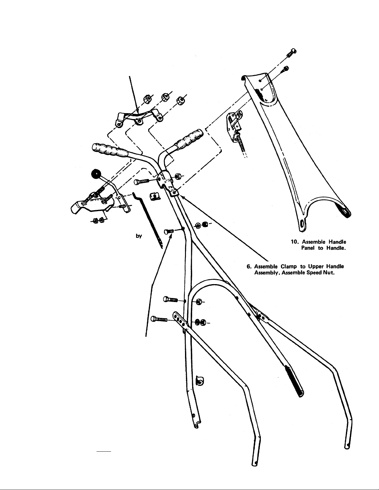
Note: Follow Assembly Instructions In Numerical Order!
7. Assemble Lockout Bracket As
Shown
8. Assemble Lockout Lever
Assembly.
1. Assemble Throttle
Control To Handle
Panel.
11. Install Grips.
9. Blade Engagement Assembly.
a. Remove Blade Spindle Cover
removing three screws.
b. Move brake lever to rear position so
belt is slack.
c. Insert ferrule into blade bracket
assembly from the left.
d. Screw rod into ferrule.
e. Assemble control handle to control
rod as shown.
f. Adjust control rod. A slight pressure
should be needed to operate lockout
lever. Too much pressure can break
lever assembly or control rods.
Readjust control rods if pressure is too
great.
g. Replace Blade Spindle Cover.
3. Assemble Two Upper Handles. Use This
Bolt Only.
5. Position Upper Handle Assembly On
Lower Handle. Adjust Handle Supports
As Desired. Fasten Upper Handle
Assembly and Handle Supports To Lower
Handle.
2. Assemble Lower Handle To Mower.
4. Assemble
Mower.
12. Check ALL nuts and bolts for correct
tightness.
it may be necessary to bend the ends of the
lower handle inward slightly to assure a snug
fit against the deck mounting area.
Handle Supports To
NOTE
Page 4

CAUTION
Please note that the chute deflector on
your mower is in an upright position.
It is held in that position by a shipping
block. This block is used for shipping
purposes only. It must be removed and
discarded before your mower is put
into operation.
Chute Doficctoi
Shipping Block to be Removed
NOTE
8. Put blade into motion by moving blade control
handle to "ON" position.
To engage the blade with the engine running . . .
a. Move the throttle control lever to "FAST" posi
tion.
b. Engage the blade engagement handle SLOWLY.
c. Adjust engine speed.
9. A brief break-in period is essential to insure maxi
mum engine and mower life. This consists of run
ning the engine at half speed for a period of time
required to use one tank of gasoline. It is also rec
ommended to change crankcase oil after the first
five hours of operation or as operating conditions
dictate. Always check oil before operating the
mower. BE SURE CRANKCASE IS FULL.
10. Proper lubrication must be maintained at ali times.
11. Appropriate clothing should be worn when cut
ting brush or heavy weeds. Safety shoes and safe
ty glasses are highly recommended.
12. The engine is stopped by moving the throttle con
trol lever to "STOP" position.
For shipping purposes your mower is
set with the wheels in a low cutting
height position. For best results raise
the cutting position until it is deter
mined which height is best for your
lawn. See adjustments.
OPERATION
1. Before starting engine, check LUBRICATION IN
STRUCTIONS.
2. Check lockout control handles for proper opera
tion. If too great a pressuré is needed to operate
these controls, damage can be done to both the
mechanism and the rods. Readjust so only slight
pressure is needed to operate both the blade en
gaging control and the self-propelled lockout con
trol. See ASSEMBLY INSTRUCTIONS Step 9.
3. Service engine with gasoline and oil. See engine
instructions for complete care and maintenance of
engine. READ DIRECTIONS CAREFULLY.
4. Be sure engine crankcase is filled to capacity with
proper grade of oil.
5. Move both control handles to "OFF" position.
6. Move throttle control lever to "CHOKE" position.
ADJUSTMENT
Handles may be adjusted by changing the position
of the lower support mounting holes. When this
change is made, it may also be necessary to check
the adjustment of control rod. See Step 9 in AS
SEMBLY INSTRUCTIONS
2. Control rod adjustments are made as shown in AS
SEMBLY INSTRUCTIONS Steps 9 and 12.
3. Cutting height adjustment is made by removing
and moving axle bolts to the desired positions. All
axle bolts must be mounted in the same relative
position to the deck. When wheels are mounted to
the deck, the crown shape washers must be assem
bled with the crown away from the deck. This is
necessary to prevent the axle bolts from loosening.
4. If throttle adjustment becomes necessary, the throt
tle control wire may be reset as follows:
a. Loosen, but do not remove, screw securing
throttle control wire assembly at engine.
b. Move throttle control lever on handle to
"CHOKE" position.
c. Move lever to which control wire is fastened to
engine to full choke position. Retighten screw
to secure throttle control wire assembly.
7. Crank engine. Move throttle control lever to
"FAST" position as soon as engine fires. Use choke
as needed to keep engine running during warm
up period.
Page 5
LUBRICATION
Cutting Blade—Remove all
the blade to the blade hub.
nuts and bolts holding
Important: Always stop engine and disconnect spark
plug wire before cleaning, lubricating or doing any
kind of work on the lawn mower.
1. Wheels—Front wheel bearings are of self-lubricat
ing Fortiflex. They require no lubrication. Rear
wheels of Lifetime graphoil bearings require little
lubrication. A light tiim of oil applied to these
bearings will reduce normal friction.
2. Throttle—Periodically lubricate throttle control lever
and entire length of throttle wire assembly with a
few drops of SAE 30 engine oil for ease of opera
tion.
3. Engine—Follow engine manual for lubrication in
structions. Check oil level before each mowing.
4. Friction point between idler bracket assembly (Ref.
No. 94) and deck should be greased once each sea
son with a multi-purpose grease.
5. Blade Spindle Assembly—The Blade Spindle Assem
bly is equipped with a grease fitting. Use grass dis
charge chute for access to the fitting located under
the deck. Use multi-purpose grease. Lubricate PRIOR
to initial use and every 25 hours thereafter. Caution:
Be sure spark plug wire is disconnected and
grounded.
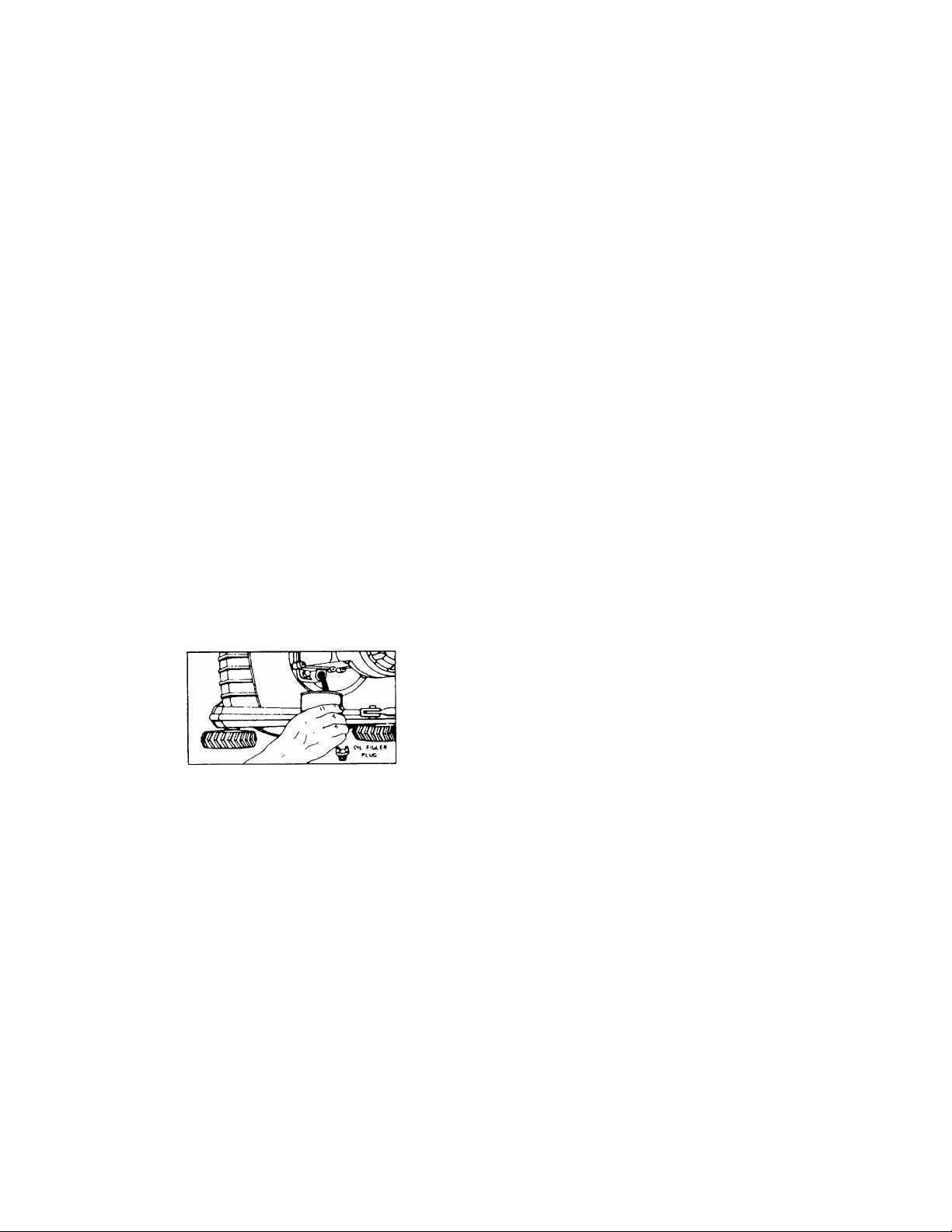
NOTE: FILL AND DRAIN OIL FROM OIL FILL PLUG.
Always disconnect spark plug cable during repairs,
refueling or changing oil. Engine oil may be drained
through oil filler opening by tilting the mower on its
side. Change oil after first 5 hours of operation while
engine is warm. Thereafter, change oil every 25 hours
of operation while engine is warm.
6. Protective Shield — The pivot points on the pro
tective shield should be lubricated periodically with
oil to prevent any rust or binding up.
7. Chute Deflector — The torsion spring and pivot point
should be lubricated periodically with oil to pre
vent any rust or binding up. Deflector must work
freely.
When sharpening blade, follow the original angle
of grind as a guide. It is extremely important that
each cutting edge receives an equal amount of
grinding to prevent an unbalanced blade. An un
balanced blade will cause excessive vibration when
rotating at high speeds and may cause damage to
the mower. Upon reassembling, make certain all
parts are assembled properly and tightened secure
ly-
2. Deck—The underside of mower deck should be
cleaned after each period of use as grass clippings,
leaves, dirt and other matter accumulates. This ac
cumulation of grass clippings, etc. is undesirable as
it will invite rust and corrosion and may cause an
uneven discharge of grass clippings at next cutting.
The deck may be cleaned by tilting the mower back
ward or on its side and scraping clean with a suit
able tool or by washing with a stream of water
from a garden hose. Caution: Do not direct the
stream of water at a hot engine as damage to the
engine may result.
3. Belt replacement may be made as follows:
a. Remove blade spindle cover.
b. Remove front belt guard.
c. Remove blade tension spring.
d. Loosen belt on bracket of idler bearing assem
bly.
e. Remove bracket lever assembly.
f. Remove damaged or worn belt.
g. Place new belt on engine pulley. Do not bend
belt guard pins. Belt should be inside of pins.
h. Work belt to front and mount on blade spindle
pulley. Replace front belt guard.
i. Replace brake lever assembly.
j. Slip belt on idler pulley between pulley and belt
bracket.
k. Replace blade tension spring.
l. Move blade lockout handle to "ON" position.
m. Position belt bracket on idler pulley to clear the
tightened belt. Secure belt bracket in position.
See drawing on page 2.
n. Replace blade spindle cover.
MAINTENANCE
important: Always stop engine and disconnect spark
plug wire before cleaning, lubricating or doing any
kind of work on the lawn mower.
NOTE
To insure safe operation of your unit,
ALL nuts and bolts must be checked
periodically for correct tightness.
Page 6

4. Storage—The following steps should be taken to
prepare the lawn mower for storage:
a. Clean and lubricate mower thoroughly as de
scribed in the proceeding instructions.
b. Refer to engine manual for correct engine stor
age instructions.
USING YOUR ROTARY MOWER
c. Coat mower's cutting blade with multi-purpose
grease to prevent rusting.
d. Place blocks under deck to raise tires clear of
floor.
For best results do not cut wet grass because it tends to
stick to the underside of the mower, thus preventing
proper discharge of grass clippings. If wet grass must
be cut, reduce walking speed to help distribute the
clippings more effectively.
New grass should be treated as wet grass, otherwise a
normal walking speed is about the right pace for effi
cient mowing.
BLADE IDLER BRACKET ASSEMBLY DETAIL
Brake Shoe 754^7
The best mowing pattern is one that allows the clip
pings to discharge towards the uncut part of the lawn.
This permits recutting of the clippings to further pul
verize them. When cutting high weeds, discharge
towards cut portion then recut at right angle to first di
rection.
Lawns should be cut in fall as long as there is growth.
belt is loose. This may be checked by removing the
blade spindle cover.
Page 7

Clip Must Not Touch
"SBelt Where Blade Is
ed.
Page 8

114-530A
IF YOU WRITE TO US ABOUT THIS ARTICLE
OR IF YOU ORDER REPLACEMENT PARTS AL
WAYS MENTION THIS MODEL & SERIAL NO
MODEL
Page 9

PARTS LIST FOR MODEL 114-530A
REF.
NO.
1
2
3
PART
746-128
COLOR
NO.
CODE
—
7861 Clamp Bracket
4 710-606
5
6
8376
712-526
7 712-107
8
9
10
11
12
8378
9354
720-157
7889
8373
13 711-180
14 736-108
712-107
15
712-107
16
17
710-606
710-606
18
19 712-107
20
8327 Lower Handle Support—L.H.
21 712-130
22 738-234
23
25
26
27
28
29
30
31
32
33
34
35
36
37
9372
711-179
710-209
9362
712-107
710-102
8328
736-119.
712-123 Hex Nut 5/ 16-24
746-171
11815—458 Control Panel
710-407
710-192
8325—458
DESCRIPTION
Engine
Cable Clip for %" Tubing
Hex Scr. '/4-20 X 1.50" Lg.*
Lockout Brkt. Ass'y.
Speed Nut #10-24
Hex Center Locknut ’^-20 Thd.
Clamp Bracket
Upper Handle (2-Req'd.)
Grip
Plastic Ball
Lockout Lever Ass'y. with
Plastic Ball
Control Rod
Fl.-Wash. .510 I.D. x .750 O.D.
Hex Center L-Nut !4-20 Thd.
Hex Center L-Nut Va-2Q Thd.
Hex Scr. 14-20 X 1.50 Lg.
Hex Scr. 1/4-20 X 1.50" Lg.*
Hex Center L-Nut 14-20 Thd.
Hex Inserted L-Nut %-16 Thd.
Shoulder Scr. .500" Dia, x .295
Pivot Bracket
Adjustable Ferrule
Hex Sems Scr. %-16 x .62
Lower Handle
Hex Center L-Nut 14-20 Thd.
Hex Scr. 14-20 x 2.50" Lg.*
Lower Handle Support—R.H.
L-Wash. 5/ 16
Throttle
Slot Hex Hd. Self Extr. Scr. #8-
32 X .50
Truss Mach. Scr. #10-24 x .38
Belt Trap Ass'y.
NEW
PART
*For faster service obtain standard nuts and bolts locally. If these items
(458—Arctic Blue)
The engine is not under warranty by the mower manufacturer.
If repairs or service is needed on the engine/ please contact
your nearest authorized engine service outlet. Check the ^'Yellow
Pages" of your telephone book under "Engines—Gasoline."
cannot be obtained locally, order by part number and size as shown
on the parts list.
When ordering parts, if color or finish is important, use the appropriate
color code shown at left. (e.g. Arctic Blue—11815 (458)
Find It Peat
'YMIew Peges'
leflie
Page 10

114-530A
IF YOU WRITE TO US ABOUT THIS ARTICLE
OR IF YOU ORDER REPLACEMENT PARTS AL
WAYS MENTION THIS MODEL & SERIAL NO
MODEL-
10
Page 11

PARTS LIST FOR MODEL 114-530A
PART
REF.
NO.
1
2
3
4
5
6
8
9
712-130
736-300
756-199
710-158
736-235
NO.
9373
4563
11993—458
COLOR
CODE
10 736-217
11
710-152
12
710-158
14
712-130
15 8324—458
16 736-119
V
712-123
18
19
12278
9.925
20 736-921
21
712-922
22 9371
23
736-108
24
738-234
25 754-109
26 732-158
27
756-206
NEW
DESCRIPTION
PART
Control Rod
Hex Ins. Jam Nut %-24 Thd.
Belt Clip
Fl.-Wash.
Flat Idler with Flange
Frame Ass'y. N
Hex Scr. 5/16-24 x 1.25
Fl.-Wash. .406" I.D. x 1.25"
O.D. x .164
Spring L-Wash. %" Scr. H.D.
Hex Scr. %-24 x 1.00" Lg. H.T.
Hex Scr. 5/ 16-24 x 1.25
Hex Ins. Jam Nut%-24 Thd
Belt Guard
Spring L-Wash. 5/16" Scr.*
Hex Nut 5/16-24
Idler Brkt. Ass'y. w. Brake Shoe
Sheave Ass'y.—4" Dia.
(Blade Spindle)
Spring L-Wash. ’/2" Scr.*
Hex Jam Nut ’/2-20 Thd.
Brake Lever
Fl.-Wash. .510" I.D. x .75"
O.D. X .033
Shoulder Scr .500" Dia. x .295
"V"-Belt '/2" X 43" Lg.
Blade Tension Spring
Engine Pulley 4.00" O.D.
(458—Arctic Blue)
The engine is not under warranty by the mower manufacturer.
if repairs or service is needed on the engine, please contact
your nearest authorized engine service outlet. Check the "Yellow
Pages" of your telephone book under "Engines—Gasoline."
*For faster service obtain standard nuts and bolts locally. If these items
cannot be obtained locally, order by part number and size as shown
on the parts list.
When ordering parts, if color or finish is important, use the appropriate
color code shown at left. (e.g. Arctic Blue—11815 (458)
Find It F«tl
laTiM
'Vtllew Pag«s'
11
Page 12

114-530A
IF YOU WRITE TO US ABOUT THIS ARTICLE
OR IF YOU ORDER REPLACEMENT PARTS AL
WAYS MENTION THIS MODEL & SERIAL NO
MODEL.
30
12
Page 13

PARTS LIST FOR MODEL 114-530A
REF.
NO.
PART
NO.
1
710-117
2
710-158
3
11993
4
710-209
5 710-567
6 712-107
7
11650
8 11193
9 718-132
DESCRIPTION
Hex Scr. 5/16-24 x 1.00" H.T.
Hex Scr. 5/16-24 x 1.25" Lg.*
Frame Ass'y.
Hex Sems Scr. %-16 x .62" Lg.*
Hex Sems Scr. 'A-28 x %" Lg.
Hex Cent. L-Nut L4-20
Deck Ass'y.—22 in.
Protective Shield Ass'y.—Comp.
Oil Cap
10 741-113 Ball Brg. .504 I.D. x 1.38 Dia.
1 1 738-114
12
13
14
11679- -458
732-253 Torsion Spring
726-106
15 11130- -458
16 711-555
17 10769
734-439
18
19
734-180
734-392
Should. Scr. .498" Dia. x 4.755"
Chute Deflector Ass'y.
Push Cap
Adapter Plate
Pivot Pin
Blade Adapter Kit
16" Rear Wheel Ass'y.—Comp.
16" Rear Wheel—Less Tire
Semi Pneumatic Tire 16 x 1.75
20 741-178 Ball Brg. .38 I.D.
710-427
21
734-642
22
23 736-105
24 738-251
25 714-365
26 712-123
27
736-119
28
742-125
29
710-117
30 710-459
736-217
31
32 7919
33 10769
34
712-123
736-119
35
Hex Scr. %-16 X 2.00" Lg.*
Front Wheel Ass'y. Comp.
Belleville Washer
Blade Spindle
#6 Hi-Pro Key 5/32 x %" Dia.
Hex Nut 5/16-24 Thd.*
L-Wash. 5/16" Scr.*
22" Blade
Hex Scr. 5/16-24 x 1.00" H.T.
Hex Scr. %-24 x 1.50" Lg. H.T.
Spring L-Wash. %" Scr. H.D.
Scalp Plate
Blade Adapter Kit
Hex Nut 5/16-24 Thd.*
L-Wash. 5/16" Scr.*
36 712-123 Hex Nut 5/16-24 Thd.*
37 736-119
38 712-123
Spring L-Wash. 5/16" Scr.*
Hex Nut 5/16-24 Thd.*
39 12281 Blade Reinforcement Plate
712-123 Hex Nut 5/16-24 Thd.*
40
41 736-119
42
8253 Bearing Housing
L.-Wash. 5/16" Scr.*
43 741-919 Ball Bearing
44
45
8253 Bearing Housing
7ft5-192
Truss Hd. Mach. Scr. 10-24x.38 Lg.
46 8295--458 Blade Spindle Cover
47 712-526
48
11679- -458 Chute Deflector Ass'y.—Comp.
Speed Nut #10-24
NEW
PART
N
N
N
N
*For faster service obtain standard nuts and bolts iocaüy. If these items
cannot be obtained locally, order by part number and size as shown
on the parts list.
(453
__
Arctic Blue) When ordering parts, if color or finish is important, use the appropriate
color code shown at left. (e.g. Arctic Blue—11815 (458)
The engine is not under warranty by the mower manufacturer.
If repairs or service is needed on the engine, please contact
your nearest authorized engine service outlet. Check the "Yellow
Pages" of your telephone book under "Engines—Gasoline."
13
Find It Fast
In Th*
'Yellow Pages'
Page 14

NOTE
The manufacturer DOES NOT recommend the use of
any accessory on this rotary mower other than those
manufactured by MTD Products Inc.
GRASS CATCHER Model No. 194-003A is available as optional
equipment for the mowers shown in this manual.
WARNING:
1. The mower should not be operated without the entire grass catcher
or chute deflector in place.
2. The mower should not be operated without the protective shield on
the rear of the deck in place.
NOTE:
Under normal usage bag material is subject to wear and should be
checked periodically. Be sure any replacement bag complies with the
mower manufacturer's recommendations.
For replacement bags, use only factory authorized replacement bag No.
764-119.
: IMPORTANT
After striking a foreign object, stop the engine (motor), remove wire
from spark plug. Thoroughly inspect the mower for any damage, and
repair the damage before restarting and operating the mower.
14
Page 15

PARTS INFORMATION
DEFECTIVE OR MISSING PARTS must be reported
to the factory immediately. Such claims must include
your model number and date of purchase.
POWER EQUIPMENT PARTS AND SERVICE
Parts and service for all MTD manufactured power
equipment are available through the authorized serv
ice firms listed below. All orders should specify the
model number of your unit, parts numbers, descrip
tion of parts and the quantity of each part required.
A 1 Engine A Mower Co.
327 E»$t 9th Street
Salt Lake City, Utah 84102
American Electric Ignition Co.
124 N. W. 8th Street
Oklahoma City, Oklahoma 73102
Auto Electric & Carburetor Co.
2S25 4th Avenue, S.
P. O. Box 1948
Birmingham, Alabama 35233
Automotive Equipment Service Co.
3117 Holmes Street
Kansas City, Missouri 64109
Bailey's Rebuild Inc.
1325 E. Madison Street
Seattle Washington 98102
Bleckrie, Inc.
7900 Lorain Avenue
Cleveland, Ohio 44102
Brown Equipment Distributor Inc.
110 Beech Street
Corydon, Indiana 47112
Bullard Supply
2409 Commerce Street
Houston, Texas 77003
Carl A. Anderson Co.
623 S. 16th Street
Omaha, Nebraska 68102
Catto A Putty, Inc.
P. O. Box 2408
510 Soledad Street
San Antonio, Texas 78205
Center Supply Company
6867 New Hampshire Avenue
Takoma Park, Maryland 20012
Dixie Sales Company
P. O. Box 1408
327 Battleground Avenue
Greensboro, North Carolina 27402
East Point Cycle A Key Shop
1617 Whiteway
East Point, Georgia 30044
Gamble Distributors
West End Avenue
Carthage, New York 13619
Garden Equipment Co., Inc.
6600 Cherry Avenue
Long Beach, California 90805
Gardenville Supply, Inc.
Pipersville, Pennsylvania 18947
Henry W. O'Neil & Assoc., Inc.
410 North Goodman Street
Rochester, New York 14609
Henzler, Inc.
2015 Lemay Ferry Road
St. Louis, Missouri 63125
Kenton Supply
8216 North Denver Avenue
Portland, Oregon 97217
Kimber't Inc.
115 W. Geddes St.
Syracuse, New York 13204
The Lawnmower Shop
1340 El Camino Real
San Carlos, California 94070
Marr Brothers
423 E. Jefferson
Dallas, Texas 75203
Mathews Auto Electric Co.
420 East 2nd Street
Tulsa Oklahoma 74120
McClure Lawn A Garden Supply
1114 Lexington Avenue
Mansfield, Ohio 44907
Memphis Cycle A Supply Co.
421 Monroe Avenue
Memphis Tennessee 38103
Morton B. Collins Co.
300 Birnie Avenue
Springfield, Massachusetts 01107
Moz-AII of Florida, Inc.
365 Greco Avenue
Coral Gables, Florida 33146
BRIGGS & STRATTON, TECUMSEH AND PEERLESS
PARTS AND SERVICE
Briggs & Stratton, Tecumseh and Peerless parts and
service should be handled by your nearest authorized
engine service firm. Check the yellow pages of your
telephone directory under the listing Engines —
Gasoline, Briggs & Stratton or Tecumseh Lauson —
Power Products.
National Central, Div. of
Joe Sterling, Inc.
Drawer "D" 687 Seville Rd.
Wadsworth, Ohio 44281
Parts A Sales Inc.
2101 Industrial Pkwy.
Elkhart, Indiana 46514
Power Equipment Distributor
36463 So. Gratiot Avenue
Mt. Clemens, Michigan 48043
Power Lawn A Garden Equip. Co.
2551-2571 J. F. Kennedy Road
Dubuque, Iowa 52001
Radco Distributors
2403 Market Street
P. O. Box 3216
Jacksonville, Florida 32206
Raub Supply Company
James & Mulberry Sts.
Lancaster, Pennsylvania 17604
Richmond Battery A Ignition
P. O. Box 25369 - 957 Myers St.
Richmond, Virginia 23260
Smith Hardware Company
515 N. George Street
Goldsboro, North Carolina 27530
South Denver Lawn Equip. Co.
527 West Evans
Denver, Colorado 80223
Suhren Engine
8330 Earhart Blvd,
New Orleans, Louisiana 70118
Sutton's Lawn Mower Shop
Route 4, Box 343
North Little Rock, Arkansas 72117
Warner Equipment
7520 Lyndale Avenue, So.
Minneapolis, Minnesota 55423
Woodson Salas A Service
1702 North Sylvania
Ft. Worth, Texas 76111
♦
♦
♦
♦
The purpose of warranty is to protect the customer from defects in workmanship and materials,
defects which are NOT detected at the time of manufacture. It does not provide for the unlimited
and unrestricted replacement of parts. Use and maintenance are the responsibility of the cus
t
♦
♦
♦
♦
♦
♦
♦
♦
♦
♦
♦
t
tomer. The manufacturer cannot assume responsibility for conditions over which it has no
control. Simply put, if it's the manufacturer's fault, it's the manufacturer's responsibility; if
it's the customer's fault, it's the customer's responsibility.
CLAIMS AGAINST THE MANUFACTURER'S
WARRANTY INCLUDES
1. Replacement of Missing Parts on new equip
ment.
2. Replacement of Defective Parts within the
warranty period.
3. Repair of Defects within the warranty
period.
FORM NO. 770-4892
WARRANTY PARTS AND SERVICE POLICY
All claims MUST be substantiated with the
following information:
1. Model Number of unit involved.
2. Date unit was purchased or first put into
service.
3. Date of failure.
4. Nature of failure.
15
♦
♦
♦
♦
♦
t
t
t
t
♦
♦
♦
♦
PRINTED IN U.S.A.
Page 16

 Loading...