

Bolens 111-051R372 User Manual
OWNEirS GUIDE
ASSEMBLY • OPERATION • MAINTENANCE • PARTS
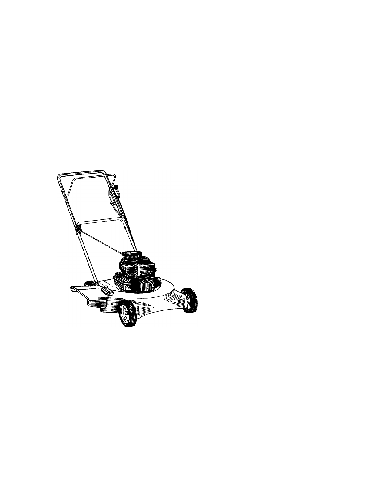
20"
$1.00
ROTARY
MOWERS
Model Numbers
111-050R304 111-051R372
i9û-ûXC.'û0Q
(Model 050R Shown)
Important: Read Safety Rules and Instructions Carefully
N
in
AMERICA
PRINTED IN U.S.A.
WARNING: This unit is equipped with an internal combustion engine and should not be used
on or near any unimproved forest-covered, brush-covered or grass-covered land unless the
engine’s exhaust system is equipped with a spark arrester meeting applicable local or state
laws (if any). If a spark arrester is used, it should be maintained in effective working order
by the operator.
In the State of California the above is required by law (Section 4442 of the California Public
Resources Code). Other states may have similar laws. Federal laws apply on federal lands.
A spark arrester for the muffler is available through your nearest engine authorized service
dealer or contact the service department, P.O. Box 360900, Cleveland, Ohio 44136.
FORM NO. 770-7626F

RULES FOR SAFE OPERATION
IMPORTANT
THIS SYMBOL POINTS OUT IMPORTANT SAFETY INSTR JCTIONS WHICH, IF NOT FOLLOWED, COULD ENDANGER THE PERSONAL SAFETY
AND/OR PROPERTY OF YOURSELF AND OTHERS. READ AND FOLLOW ALL INSTRUCTIONS IN THIS MANUAL BEFORE AHEMPTING
TO OPERATE YOUR LAWN MOWER. FAILURE TO CON PLY WITH THESE INSTRUCTIONS MAY RESULT IN PERSONAL INJURY. WHEN,
YOU SEE THIS SYMBOL- A HEED ITS WARIIING.
A"
A'
DANGER: with any type of power equ pment, careiessness or error on the part of the operator can result in serious
Your lawn mower was bull: to be operated according to the rules for safe operation in this manuai. As
A
TRAINING
Read this owner’s guide carefully in its entirety before attempting
to assemble or operate this machine. Be completely familiar with
the controls and the proper use of this machine beforj operating
it. Keep this manual in a safe place for future and reguh r reference
and for ordering replacement parts.
2. Your rotary mower is a precision piece of power equijment, not
a plaything. Therefore, exercise extreme caution at all l imes. Your
unit has been designed to perform one job: to mow grass. Do
not use it for any other purpose.
3. Never allow children under 14 years old to operate a po\ /er mower.
Children 14 years old and over should only operate mower under
close parental supervision. Only persons well acquaintec with these
rules of safe operation should be allowed to use yo jr mower.
4. Keep the area of operation clear of all persons, partici ilarly small
children and pets. Stop engine when they are in the vicinity of
your mower to help prevent blade contact or throwi object in
jury. Although the area of operation should be comple ely cleared
of foreign objects, an object may have been overlookei I and could
be accidently thrown by the mower in any direction and cause
serious personal injury to the operator or any others allowed in
the area.
PREPARATION
Thoroughly inspect the area where the equipment is o be used.
Remove all stones, sticks, wire, bones and other foreign objects
which could be picked up and thrown by the mower ir any direc
tion and cause serious personal injury to the operator oi any others
allowed in the area. Plan your mowing pattern to avoii I discharge
of material toward roads, sidewalks, bystanders anc the like.
2. Always wear safely glasses or eye shields during operal on or while
performing an adjustment or repair, to protect eyes fi om foreign
objects that may be thrown from the machine in an' direction.
3. Wear sturdy, rough-soled work shoes and close-fitting slacks and
shirts. Shirts and pants that cover the arms and leg; and steel
toed shoes are recommended. Do not wear loose titling clothes
or jewelry. They can be caught in moving parts. Ne'er operate
a unit in bare feet, sandals, or sneakers.
4. Before working with gasoline, extinguish all cigarettes, cigars, pipes
and other sources of ignition. Check the fuel level bef )re starting
the engine. Gasoline is an extremely flammable fuel Do not fill
the gasoline tank indoors, while the engine is runni ig, or until
engine has been allowed to cool for at least two m ñutes after
running. Replace gasoline cap securely and wipe off any spilled
gasoline before starting the engine as it may cause a fire or
explosion.
5. Disengage the self-propelled mechanism or drive clul :h on units
so equipped before starting the engine.
6. The blade control handle is a safety device. Never attemi it to bypass
its operation. Doing so makes the safety device inoperative and
may result in personal injury through contact with l he rotating
blade. The blade control handle must operate easily in both direc
tions and automatically return to the disengaged pos tition when
released.
7. Never attempt to make a wheel or cutting height adjus :ment while
the engine is running.
8. Never operate the mower in wet grass. Always be sjre of your
footing. A slip and fall can cause serious personal I ijury. Keep
a firm hold on the handle and walk, never run. Mow onl i in daylight
or in good artificial light.
injury. If you violate any o these rules, you may cause serious injury to yourself or others.
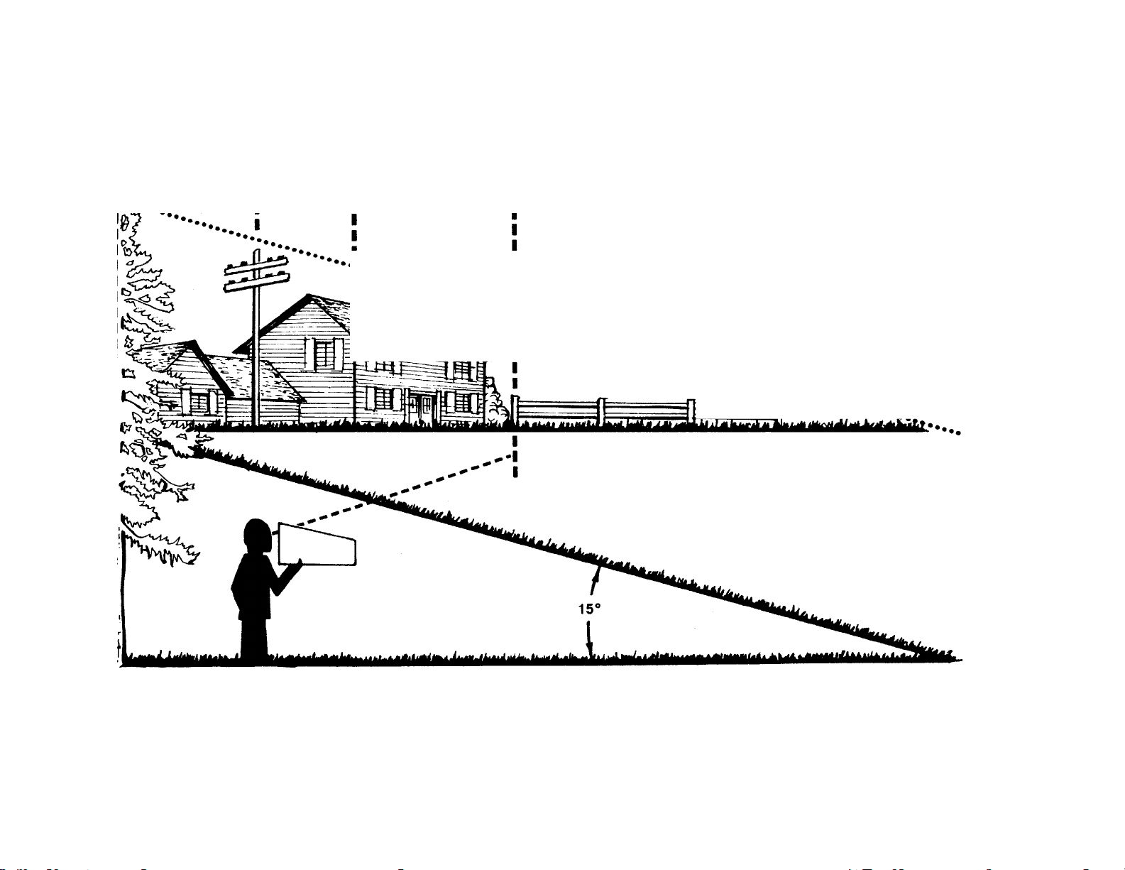
9. For your safety, use the slope gauge included as part of this manual
to measure slopes before operating this unit on a sloped or hilly
area. If the slope is greater than 15° as shown on the slope gauge,
do not operate this unit on that area or serious injury could result.
OPERATION
Do not change the engine governor settings or overspeed the
engine. Excessive engine speeds are dangerous.
Do not put hands or feet near or under rotating parts. Keep clear
of the discharge opening at all times as the rotating blade can
cause injury.
Stop the blade when crossing gravel drives, walks or roads.
After striking a foreign object, stop the engine, remove the wire
from the spark plug, and thoroughly inspect the mower for any
damage. Repair the damage before restarting and operating the
mower.
If the equipment should start to vibrate abnormally, stop the engine
and check immediately for the cause. Vibration is generally a warn
ing of trouble.
Shut the engine off and wait until the blade comes to a complete
6.
stop before removing the grass catcher or unclogging the chute.
The cutting blade continues to rotate for a few seconds after th«~
engine is shut off. Never place any part of the body in the
area until you are sure the blade has stopped rotating.
Before cleaning, repairing or inspecting, make certain the blade
and all moving parts have stopped. Disconnect the spark plug wire,
and keep the wire away from the spark plug to prevent accidental
starting.
Do not run the engine indoors.
Never cut grass by pulling mower toward you. Mow across the
face of slopes, never up-and-down. Exercise extreme caution when
changing direction on slopes. Do not mow excessively steep slopes.
Always be sure of your footing. A slip and fall can cause serious
personal injury.
Never operate mower without proper guards, plates or other safety
10.
protective devices in place.
11.
Muffler and engine become hot and can cause a burn. Do not
touch.
MAINTENANCE AND STORAGE
1. Check the blade and engine mounting bolts at frequent intervals
á£
for proper tightness. Also visually inspect blade for damage (e.g.
bent, cracked). Replace with blade which meets original equip
ment specifications.
2. Keep all nuts, bolts, and screws tight to be sure the equipment
is in safe working condition.
3. Never store the mower with gasoline in the tank or gas containers
inside of a building where fumes may reach an open flame or spark
(e.g. gas hot water heater). Allow the engine to cool before stor
ing in any enclosure.
4. To reduce fire hazard, keep the engine free of grass, leaves and
excessive oil.
5. Check the grass catcher bag frequently for wear or deterioraf
Replace a worn or damaged bag Immediately. For safety pro.
tion, replace only with new bag meeting original equipment
specifications.
-- J
-----------------------
—-------------------------------------------------------------- i J I nib Line —---------------------------------—---------------------------------------------- I
USÉ THIS SHEET AS A GUIDE TO DETERMINE SLOPES WHERE YOU MAY NOT OPERATE SAFELY.
SIGHT AND HOLD THIS LEVEL WITH A VERTICAL TREE
------------------
---------------^---------------------------------A CORNER OF A BUILDING
u
A POWER POLE
i ........
OR A FENCE POST
...........
•■■.^¡rPPe
................................
t;
(D
O
■a
0)
0)
0>
o
S'
0)
(0
0)
(D
■O
a>
o
(D
"Hh
c/>
o
o
c
o
c
(D
—I
(D
<D
<D
3
o
(D
AC WARNING ^
Do not mow on inclines with a slope in excess of 15 degrees (a rise of approximately 214 feet every 10 feet). A
riding mower could overturn and cause serious injury, if operating a walk-behind mower on such a slope, it is
extremely difficult to maintain your footing and you could slip, resulting in serious injury.
Operate RIDING mowers up and down slopes, never across the face of slopes.
Operate WALK-BEHIND mowers across the face of slopes, never up and down slopes.
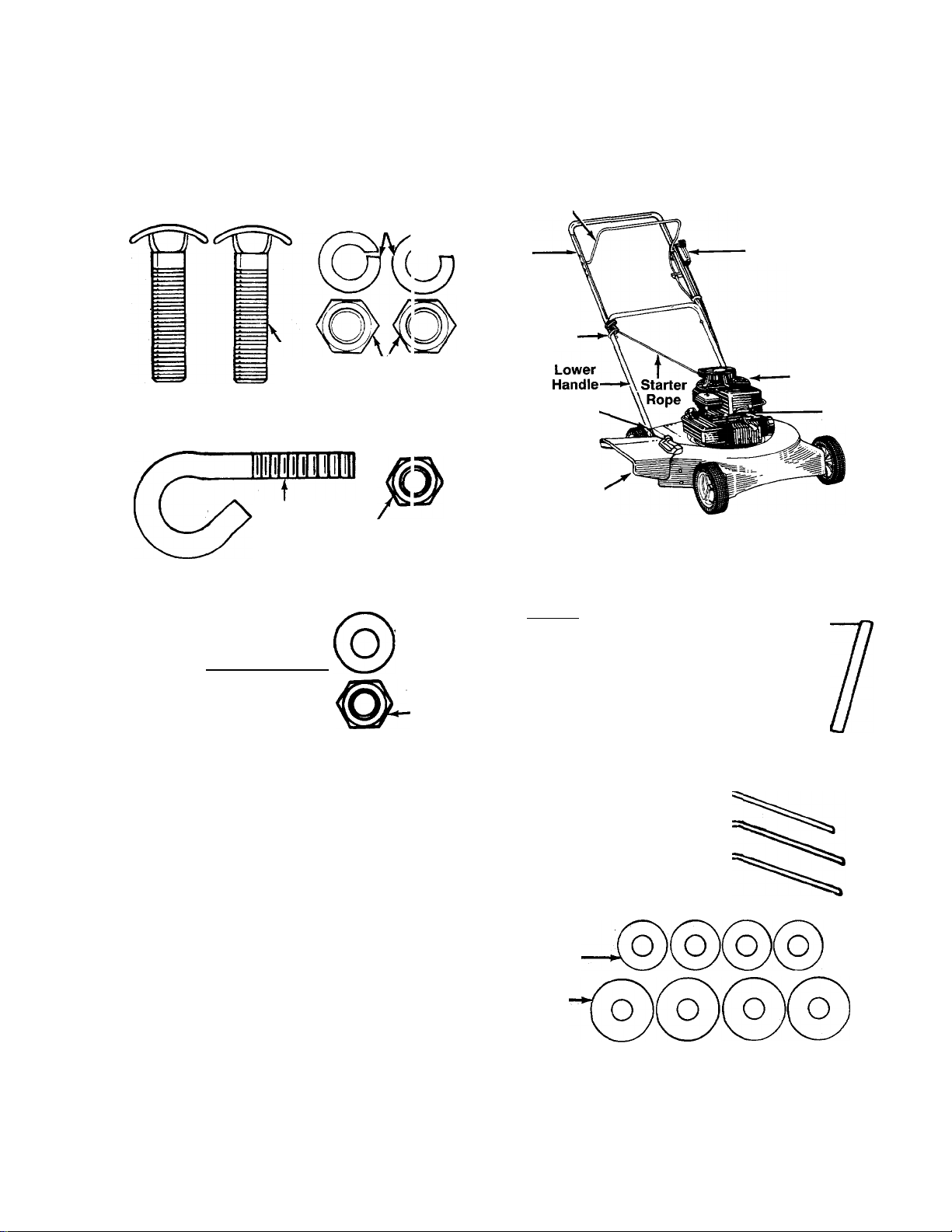
CONTENTS OF HARDWARE PACK
Remove this sheet from your owner’s manual and lay the hardware on the illustration for identification purposes. After assembly,
keep the Slope Gauge which is on the reverse sic e of this sheet for future use.
(Hardware pack contains extra items which ar; not used on your unit. Part numbers are shown in parentheses.)
ATTACHING THE
UPPER HANDLE
Curved
Head
Bolts
(710-0671)
ATTACHING THE
B
STARTER ROPE
Rope
Guide
(710-1205)
ATTACHING THE CABLE BRACKET AND
THROTTLE CONTROL
JllllllllllllllllillllllllllH
Hex Bolt
V*-20 X 1-7/8" Long
(710-1216)
Split WasI ers
5/16" I.II.
(736-011Î)
^
Hex Nuts
5/16-18 Tl read
(712-02(17)
Hex Lock Nut
V4-20 Thread
(712-032-1)
Sp ing Washer
-■1/4" I.D.
(736-0175)
Hex Nut
Vx-20 Thread
(712-0287)
Blade Control
Handle,
Upper
Handle
Rope
Guide
Handle
Mounting
Brackets
Deflector
Cable
Bracket.
(17174)\
Chute
(Model 050R Shown)
PARTS IDENTIFICATION
Throttle
Control
o
Engine
Spark
Plug
>
o
3
<D
SECURING THE CABLES
raí
1C
If
INSTALLATION OF WHEELS
(This hardware is shown one-half size)
Axle Bolts(738-0533)
I
I I I
0
INCHES
I
I I I I
Dable Ties
[726-0240)
Cupped Washers
3/8" I.D. X 7/8" O.D.
(736-0105)
Cupped Washers
3/8" I.D. X
1-1/8" O.D.
(736-0331)
Hex Nuts
3/8-16 Thread-
(712-0798)
I I I
1
I
ASSEMBLY INSTRUCTIONS
IMPORTANT: This unit is shipped WITHOUT GASOLINE
or OIL. After assembly, service engine with gasoline and
oil as instructed in the separate engine manuai packed
with your unit.
NOTE: Reference to right or left hand side of the mower is
observed from the operating position.
The instructions in this manual cover various models of
mowers. Follow only those instructions which pertain to
your unit.
Tools Required for Assembly
(1) Pair of Pliers
(1) 1/2" Wrench
(2) 7/16" Wrenches
(1) 9/16" Wrenches
(1) Adjustabie Wrench
(Two 6" Adjustable Wrenches may be used instead of the
above.)
UNPACKING
1. Remove the lawn mower from the carton by opening the
top flaps and lifting the unit out. Be careful of the staples.
Make certain all parts and literature have been removed
from the carton before the carton is discarded.
2. Disconnect and ground the spark plug wire against the
engine.
3. Stretch out all control cables and place on the floor. Be
careful not to bend or kink the cables at any time during
assembly.
4. Remove page four from this manual and lay the contents
of the hardware pack on the illustration for identification.
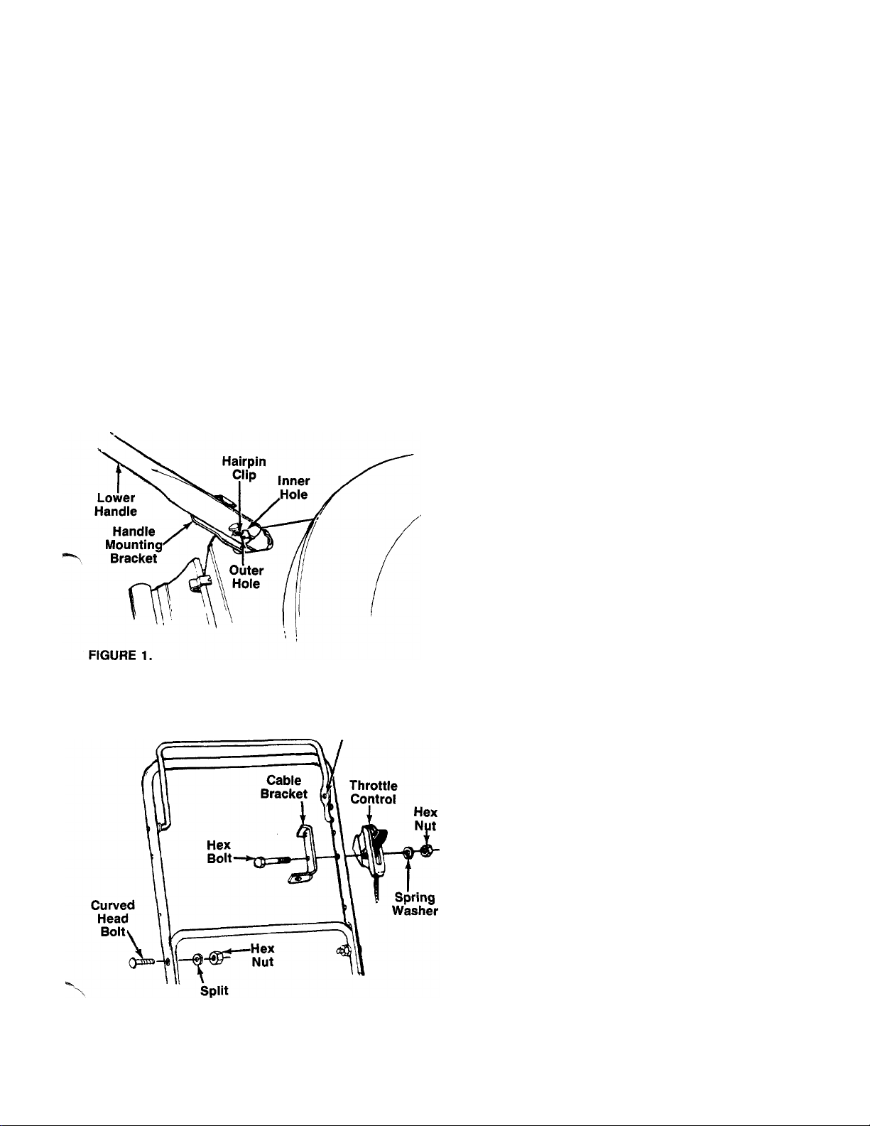
ATTACHING THE LOWER HANDLE
1. Remove the hairpin clips from the holes in the handle
brackets, which extend through the rear of the deck. See
figure 1.
2. Attach the lower handle by placing the bottom holes in
the lower handle over the weld pins on the handle
brackets.
3. Using a pair of pliers, squeeze one leg of the lower
handle against the handle mounting bracket. Insert the
hairpin clip into the inner hole on the weld pin. See figure
-------
1. Repeat on other side.
FIGURE 2.
Washer
Hole in
Blade Control
Handle
NOTE: There are two (2) holes in the handle mounting
brackets. Place the hairpin clip in the inner hole for operation.
Outer hole is for storage.
ATTACHING THE UPPER HANDLE (Hardware A)
1. Place the upper handle in position over the lower han
dle. The hole in the side of the blade control handle (at
tached to the upper handle) must be on the left side.
2. Secure the upper handle to lower handle using the
curved head bolts, split washers and hex nuts as shown
in figure 2.
AHACHING THE CABLE BRACKET AND THRDHLE CDNTRDL (Hardware C)
Attach the throttle control to the left side of upper handle as
-follows. See figure 2.
1. Route the throttle control cable inside the legs and
beneath the upper bar of the lower handle.
2. Place cable bracket against left side of upper handle,
lining up the hole in the bracket with the bottom hole in
upper handle. Place 1/4" hex bolt through cable bracket
and handle, from the inside to the outside.
3. Place throttle control on the hex bolt (outside of upper
handle), with the throttle lever facing upward.
4. Secure with spring washer (cupped side against the throt
tle control) and hex nut.
 Loading...