

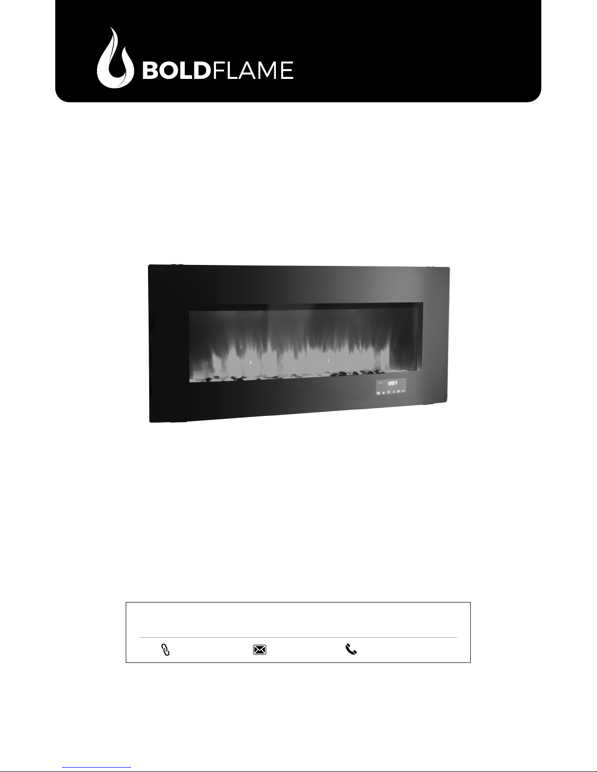
Fornitor XL
SP5293
Please carefully check the unit and make sure there is no damage when you open the carton.
QUESTIONS, PROBLEMS, OR MISSING PARTS?
Please Contact Customer Service Before Returning to Store
www.soupro.com
USER MANUAL
cs@soupro.com
Keep this manual for future reference
+1-800-239-0689
General InformatIon
Table of Contents
• GENERAL INFORMATION
FCC/ICSES Information
Safety Instructions
Warranty
• ASSEMBLY INSTRUCTIONS
Preparation
Assembly
• FIREPLACE OPERATIONS
Operating Instructions
Care And Maintenance
Troubleshooting
2
2
4
5
7
13
14
15
FCC / ICES Information
This equipment has been tested and found to comply with the limits for Class B digital devices, pursuant to part 15 of the FCC
rules. These limits are designed to provide reasonable protection against harmful interference in a residential installation.
The equipment generates, uses and can radiate radio frequency energy and, if not installed and used in accordance with
the instructions, may cause harmful interference to radio or television reception, which can be determined by turning the
equipment off and on. The user is encouraged to try and correct the interference by one or more of the following measures:
(a) Reorient or relocate the receiving antenna
(b) Increase the separation between the equipment and the receiver
(c) Connect the equipment into an outlet on a circuit different from that to which the receiver is connected.
(d) Consult the dealer or an experienced radio/TV technician for help.
This device complies with Part 15 of the FCC rules. Operation is subject to the following two conditions:
(a) This device may not cause harmful interference, and
(b) This device must accept any interference received, including interference that may cause undesired operation.
Modications not approved by the party responsible for compliance could void user’s authority to operate the equipment.
This Class B digital apparatus complies with Canadian ICES-003.
Safety Instructions
Use this rebox only as described in the manual. Any other use is NOT recommended by the manufacturer and may cause
re, electric shock or injury to persons.
CaUtIon:
• If possible, ALWAYS unplug this rebox when not in use.
• DO NOT operate any rebox with a damaged cord or plug or after the heater malfunctions.
• DO NOT operate any rebox if it has been dropped or damaged in any manner. Disconnect power at service panel and have
rebox inspected by a reputable electrician before reusing.
• Any repairs to this unit should be carried out by appropriately qualied service personnel.
• Under no circumstances should this unit be modied. Parts having to be removed for servicing must be replaced prior to
operating this unit again.
• DO NOT use outdoors.
• This unit is not intended for use in bathrooms, laundry areas and similar indoor locations. NEVER place heater where it may
fall into a bathtub or other water container.
• To disconnect this unit, turn all controls to the OFF position, then remove plug from outlet.
• ONLY connect to properly grounded outlets.
• This appliance, when installed, must be electrically grounded in accordance with local codes, with the current CSA C22.1
Canadian Electrical Code or, for USA installations, follow the National Electrical Code, ANSI/NFPA NO.70.
2
• To prevent a possible re, DO NOT block any air intakes or exhaust in any manner. DO NOT use on soft surfaces, like a
bed, where opening may become blocked.
• ALWAYS plug this unit directly into a wall outlet/receptacle. NEVER use with an extension cord or relocatable power tap
(outlet/power strip).
• This heater includes an automatic protection system that will shut off the unit to prevent overheating. If the unit is at risk of
overheating, the front panel will display "E1" and a thermal cut out will shut off the heater to prevent damage or risk of re.
• DO NOT slide rebox on top of wood to avoid scratching wood surface.
• DO NOT place any objects on top of rebox and top air intake vents as this will cause the unit to overheat and can cause a
re.
Please read and understand this entire manual before attempting to assemble, operate or install the product.
IMPORTANT NOTICE
When using electrical appliances, basic precautions should always be followed to reduce the risk of re, electric shock
and injury to persons, including the following:
WARNING: Place this unit in a location that avoids direct sunlight and high temperatures.
WARNING: Plastic bags, nails, etc. should be kept out of reach of children.
WARNING: This appliance is hot when in use. To avoid burns, DO NOT let bare skin touch hot surfaces. Keep
combustible material, such as furniture, pillows, bedding, papers, clothes and curtains, at least 3 feet from the front
of the heater and keep them away from the side and rear.
WARNING: Extreme caution is necessary when any heater is used by or near children or individuals with
disabilities and whenever the replace is left operating and unattended.
WARNING: DO NOT run cord under carpeting. DO NOT cover cord with throw rugs, runners, or similar covering.
Do not route cord under furniture or appliances. Arrange cord away from traffic areas and where it will not be
tripped over.
WARNING: DO NOT insert or allow foreign objects to enter any ventilation or exhaust opening as this may cause
an electric shock or re, or damage the appliance.
WARNING: This appliance has hot and arcing or sparking parts inside. DO NOT use it in areas where gasoline,
paint or ammable vapors or liquids are used or stored. This replace should not be used as a drying rack for
clothing. Christmas stockings or decorations should not be hung in the area of it.
General InformatIon
eleCtrICal ConneCtIon:
• A 15-amp, 120-volt, 60 Hz circuit with a properly grounded
outlet is required. Preferably, the fireplace will be on
a dedicated circuit as other appliances on the same
circuit may cause the circuit breaker to trip or the fuse
to blow when the heater is in operation. The unit comes
standard with 6-ft. three-wire cord, exiting from the rear
of the fireplace. DO NOT exceed the current rating of
the current tap. ALWAYS plug this unit directly into a wall
outlet/receptacle. NEVER use with an extension cord or
relocatable power tap (outlet/power strip).
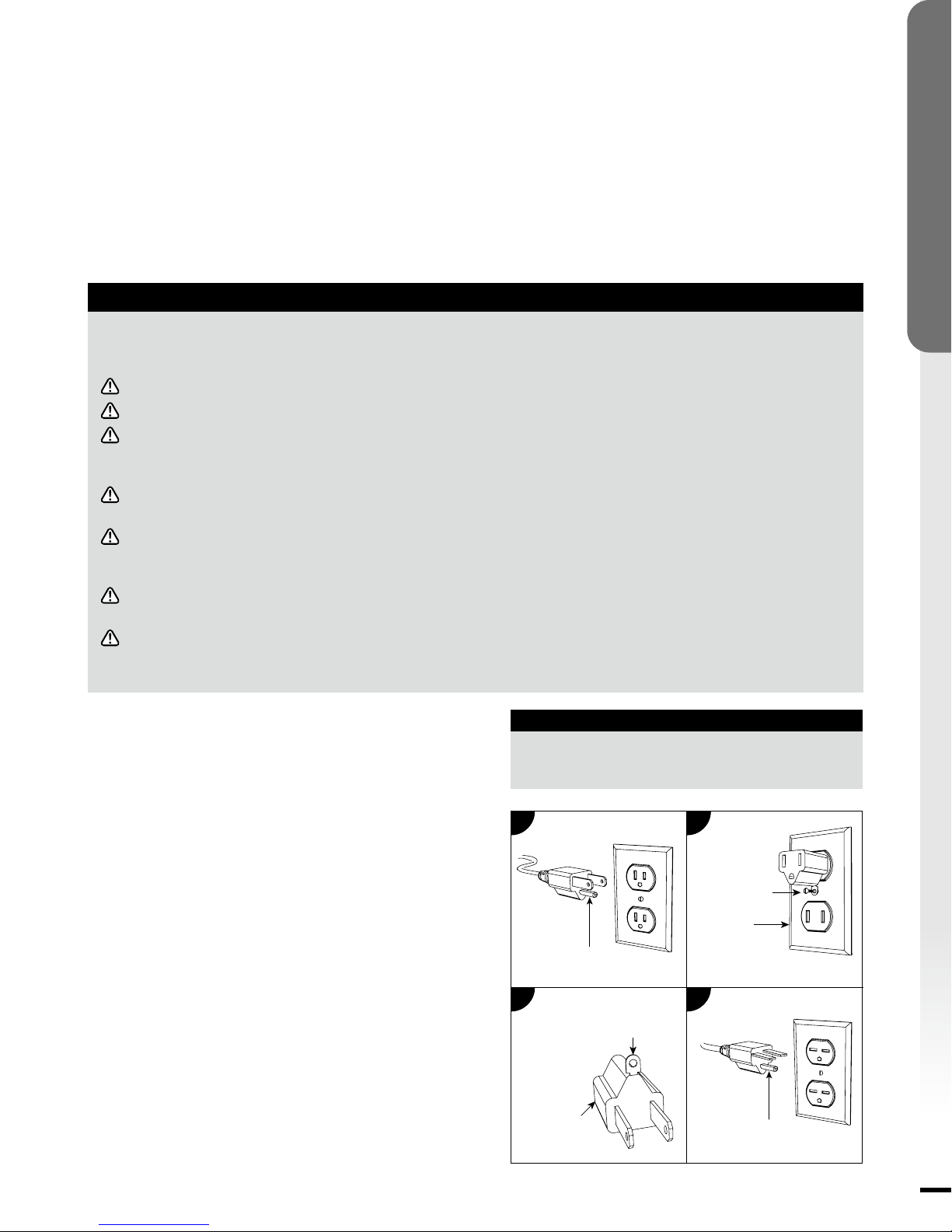
• This rebox is for use on 120 volts. The cord has a plug as
shown below. See illustration for grounding instruction. An
adapter as shown at C is available for connecting threeblade grounding type plugs to two-slot receptacles. The
green grounding lug extending from the adapter must
be connected to a permanent ground such as a properly
grounded outlet box. The adapter should not be used if a
three-slot grounded receptacle is available.
a
Grounding Pin
C
Grounding Means
Adapter
eleCtrICal SPeCIfICatIonS
Voltage:
Amps:
Watts:
120 VAC, 60 Hz
11.7 Amps
1400 Watts
B
Metal Screw
Cover of
Grounding Box
D
Grounding Pin
3
GENERAL INFORMATION
Warranty
1-YEAR LIMITED WARRANTY
Source Pro USA Inc. (hereinafter referred to collectively as “the Company”) warrants that your new Bold Flame Electric
Fireplace is free from manufacturing and materials defects for a period of one (1) year from date of purchase. Subject to the
following conditions and limitations:
1. The electric fireplace must be installed and operated at all times in accordance with the installation
and operating instructions furnished with the product. Any unauthorized repair, alteration, willful abuse,
accident, or misuse of the product shall nullify this warranty.
2. This warranty is non-transferable, and is made to the original owner, provided that the purchase was
made through an authorized supplier of the Company.
3. The warranty is limited to the repair or replacement of part(s) found to be defective in material or
workmanship – provided that such part(s) have been subjected to normal conditions of use and service –
after said defect is conrmed by the Company’s inspection. All replacement parts or products will be new,
remanufactured, or refurbished.
4. The Company may, at its discretion, require that any defective part(s) be returned in exchange for the
replacement part(s).
5. The Company may, at its discretion, fully discharge all obligations with respect to this warranty by
refunding the wholesale price of the defective part(s).
6. This warranty does not cover the LED light bar included with the electric replace.
7. Any installation, labor, construction, transportation, or other related costs/expenses arising from defective
part(s), repair, replacement, or otherwise of same, will not be covered by this warranty, nor shall the
Company assume responsibility for the same.
8. The owner/user assumes all other risks – if any – including but not limited to the risk of any direct, indirect
or consequential loss or damage arising out of the use, or inability to use the product, except as provided
by law.
9. All other warranties – express or implied – with respect to the unit, its components and accessories, or
any obligations/liabilities on the part of the Company are hereby expressly excluded.
10. The Company neither assumes, nor authorizes any third party to assume on its behalf, any other liabilities
with respect to the sale of the unit.
11. The warranties as outlined within this document do not apply to non-accessories used in conjunction with
the installation of this product.
12. This warranty gives you specic legal rights, and you may also have other rights which vary from state to
state.
This warranty is void if:
(a) The replace is subjected to prolonged periods of dampness or condensation.
(b) Any unauthorized alteration, willful abuse, accident, or misuse of the product.
(c) You do not have the original purchase receipt.
www.soupro.com
Make sure you have the following information ready:
• Warranty
• Sales Receipt
• Product Model/Serial Number
• Date of Purchase
• Location of Purchase
4
IF WARRANTY SERVICE IS NEEDED
Please Contact Customer Service
cs@soupro.com
+1-800-239-0689
Preparation
IMPORTANT INFORMATION
1. Before you begin, locate the instructions and hardware. Be sure you have all of the parts and can identify
them.
2. To avoid scratching the finish, assemble the product on a soft, non-abrasive surface such as carpet or
cardboard.
3. Assembly of this product may require more than one person.
4. Selectalocationthatis notsusceptible tomoisture,dustandisawayfrom hightrafc locationsandthings
thatmanycatchreorblockopeningssuchasdrapes,pillows,furnitureetc.
5. It is strongly recommended that the screws be screwed into the wall studs where possible. If the wall studs
cannot be used, wall anchors must be used.
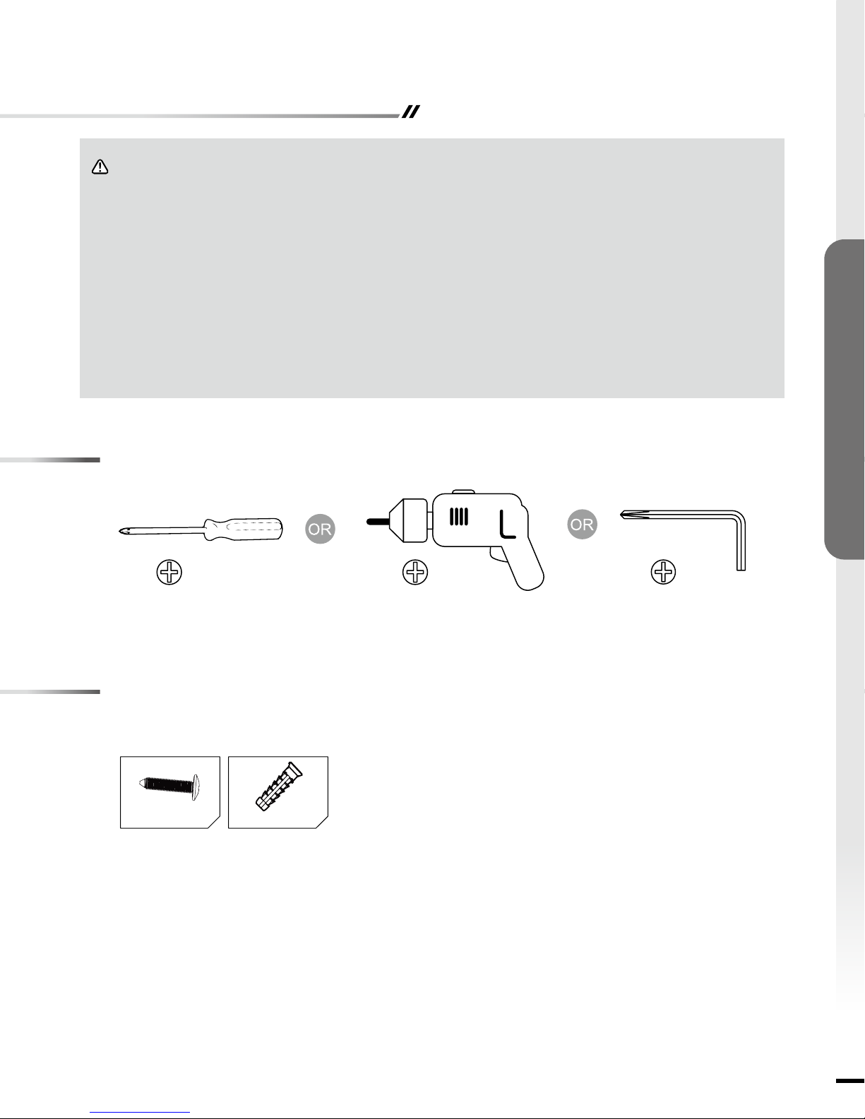
CAUTION: Enclosed wall anchors (BB) only can be use on the concrete wall.
6. Forthebesteffectinstallthereplaceoutofdirectsunlightandawayfromoverheadlighting.
Tools Required
ASSEMBLY INSTRUCTIONS
Philips Screwdriver Hand Drill Hex Key
Hardware Identication
Number of spare hardware is indicated in ( ).
BB x 4AA x 4
(Tool Included)
5
Preparation
ASSEMBLY INSTRUCTIONS
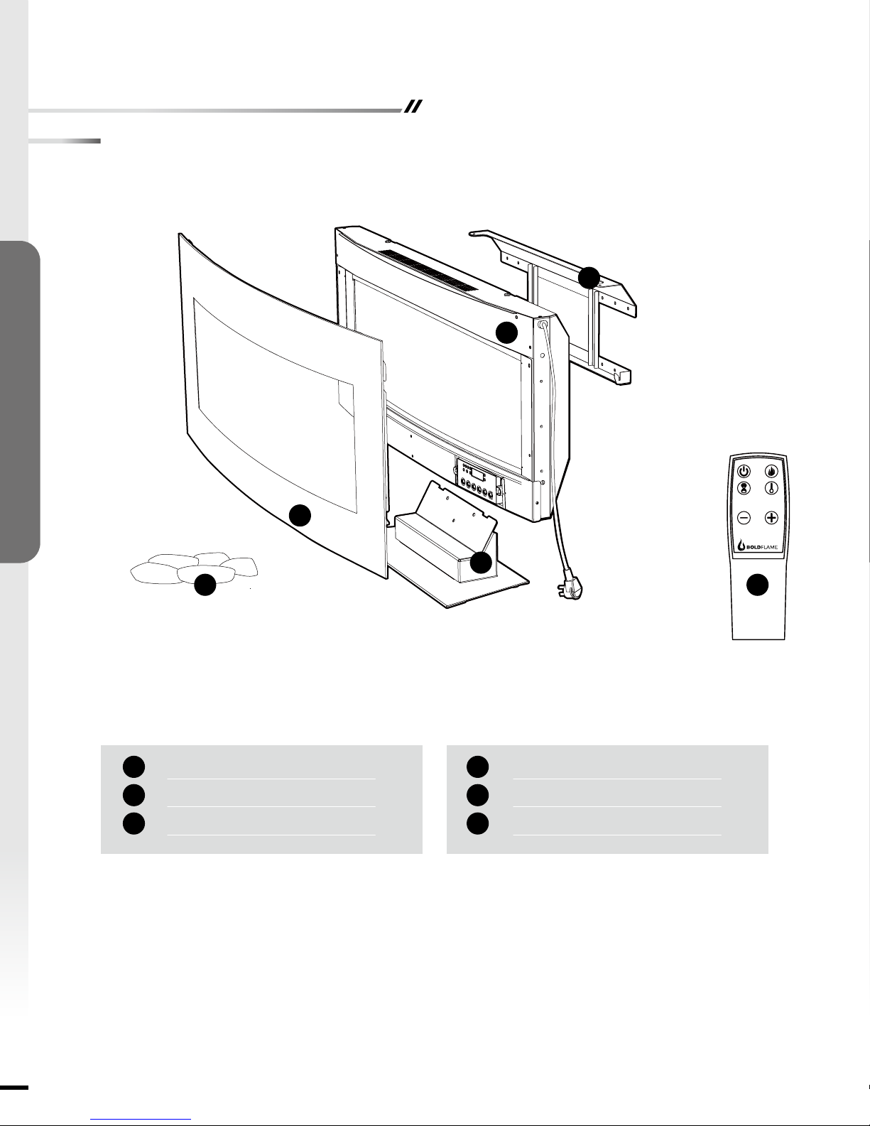
Parts List
D
C
Front Glass Cover
A
Base
B
Fireplace
C
A
B
EF
x 1
x 1
x 1
Mounting Bracket
D
Remote Control
E
Rocks
F
x 1
x 1
x 1
6
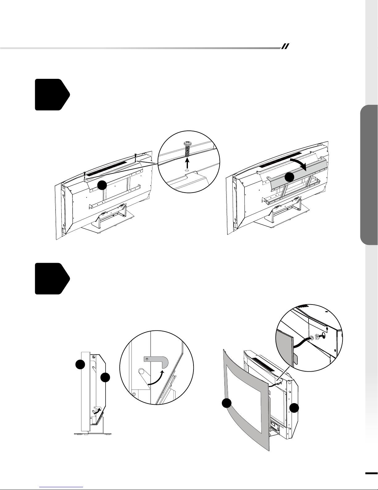
Assembly - Wall Mount Installation
Remove mounting bracket (D) from back of replace (C) by unscrew two screws at the top
of the unit.
1.
D
ASSEMBLY INSTRUCTIONS
D
2.
Release the latches on the both side to unlock the front glass as illustrated below. Carefully
pull the front glass (A) slightly away from the replace (C) and set down. Then gently pull
the release tab on the cable and nish removing front glass (A).
CAUTION:
A
C
Be careful of the cable connecting the front glass to the replace.
A
C
7

Assembly - Wall Mount Installation
3.
ASSEMBLY INSTRUCTIONS
Remove the base (B) of replace (C) by unscrewing three screws at the rear base of the
unit.
C
B
B
4.
Choose a wall location to attach the mounting bracket (D). Position the mounting bracket
(D) in the desired location. Use a level to align the bracket and mark the four holes with a
pencil.
D
Minimun height: 9in
8

Assembly - Wall Mount Installation
Select the hardware appropriate for mounting bracket installation.
5.
STUD WALL
• Secure the mounting bracket (D) to wall using screws (AA) at marked stud locations.
DRYWALL
• Drill holes at marked locations and secure the mounting bracket (D) to the wall with toggle
bolts and washers (not included).
CONCRETE WALL
• Drill 5/16-inch holes at marked locations, then insert wall anchors (BB) into holes. Secure
the mounting bracket (D) to wall using screws (AA).
D
AA
D D
STUD WALL DRYWALL CONCRETE WALL
BB
ASSEMBLY INSTRUCTIONS
AA
6.
Hang the fireplace (C) on the hooks at bottom of mounting bracket (D) and push the
replace (C) into mounting bracket (D). Re-fasten the two screws removed in Step 1.
9

Assembly - Wall Mount Installation
7.
ASSEMBLY INSTRUCTIONS
Distribute the rocks (F) evenly in the tray of the replace (C).
F
C
8.
Re-install the front glass (A) to the replace (C), and connect the mood light cable.
A C
A
C
10
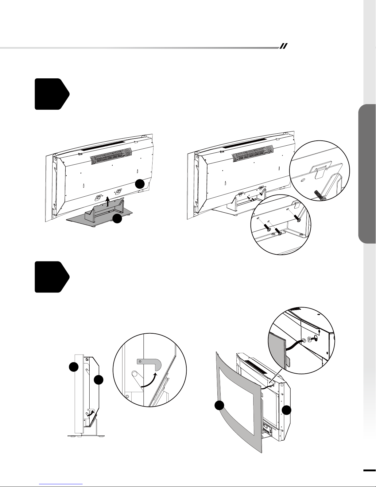
Assembly - Free Standing Installation
Assembly the base (B) of replace (C) by fasten three screws.
1.
C
B
ASSEMBLY INSTRUCTIONS
2.
Release the latches on the both side to unlock the front glass as illustrated below. Carefully
pull the front glass (A) slightly away from the replace (C) and set down. Then gently pull
the release tab on the cable and nish removing front glass (A).
CAUTION:
A
Be careful of the cable connecting the front glass to the replace.
C
A
C
11

Assembly - Free Standing Installation
3.
ASSEMBLY INSTRUCTIONS
Distribute the rocks (F) evenly in the tray of the replace (C).
F
C
4.
Re-install the front glass (A) to the replace (C), and connect the mood light cable.
12

Operating Instructions
AM
PM
Power Button
• Press the POWER button to turn ON or OFF the unit.
• When the unit is in ON mode, touch control panel light
will fully light up for 8 sec and then shut down if without
any others operation including remote control.
• When the unit is in OFF mode, the POWER symbol
LED will Semi-bright. When power OFF, unit will be
stopped, if heater is working before power OFF the
unit, fan will have 20 seconds delay to ensure heat will
not be trapped inside the unit.
Each time the replace is plugged in, a 5-second fan and
heater will turn on for internal check program.
The unit has a memory function with last settings for
heating level and ame brightness effect, unless the main
power to the unit has been interrupted.
Flame Button
• Press the ame button to cycle through the setting as:
Flame Brightness (FL), Flame Color (FC), Mood Light
Brightness (bL), Mood Light Color (bC)
Flame Brightness Setting
• Press “Flame” key until FL0 / FL1 / FL2 / FL3 / FL4 /
FL5 shown on the display, and then press “+” key or “-”
key to adjust the ame brightness from level 0 to level 5.
Flame Color Setting
• Press “Flame” key until FC1 / FC2 / FC3 / FC4 / FC5 /
FC6 shown on the display, and then press “+” key or “-”
key to adjust the ame color.
Setting Color
FC1
FC2
FC3
Yellow
Blue
Yellow + Red
Mood Light Brightness Setting
• Press “Flame” key until bL0 / bL1 / bL2 / bL3 / bL4 /
bL5 shown on the display, and then press “+” key or “-”
key to adjust the mood light brightness from level 0 to
level 5.
Mood Light Color Setting
• Press “Flame” key until bC1 / bC2 / bC3 / bC4 / bC5
/ bC6 / bC7 / bC8 / bC9 / bC10 shown on the display,
and then press “+” key or “-” key to adjust the mood
light color.
Setting Color
Yellow + Blue + Red
FC4
FC5
FC6
Yellow + Blue
Color Rotation
°
F
°
C
Setting Color
bC1
bC2
bC3
bC4
bC5
bC6
Red
Orange
Yellow
Green
Cyan
Blue
Setting Color
bC7
bC8
bC9
bC10
Purple
White
Above 8 colors
gradually changed
RGB 3 colors
gradually changed
Timer Button
Timer Setting
• Timer can be adjusted when heater is ON. It can
adjusted from 0 hour (OFF) to 9 hours with 0.5 hour
interval.
• When TIMER is activated, the symbol will be displayed.
• When TIMER digital is 0 H, TIMER function is invalided.
The TIMER symbol will automatically disappear.
Clock Setting
• For clock setting, hold the TIMER key for 5s, hour
display will flashing. Push UP “+” or DOWN “-” key,
Hours setting can be adjusted. Touch the TIMER key
once more, minute display will ashing. Minutes setting
can be adjusted as the same way as hours setting.
• When clock is at the setting mode, hold UP (“+”) and
DOWN (“-”) keys together to select 12H or 24H mode.
The unit default setting is 24H. The AM or PM symbol
will automatically displayed when the 12H mode was
selected.
• Press the timer key can exit the setting or it will
automatically exit after 8s without any further operation.
Heater Button
• HEATER key is used to control ON/OFF of the heater.
Push UP (“+”) or DOWN (“-”) key to to scroll through
the pre-set temperature range from 59°F (15°C) to
86°F (30°C), ON & OF (OFF). Heater will turned ON
accordingly to the set temperature. When the ambient
temperature is higher than the set temperature, heater
will automatically turned OFF.
• When the temperature is set at “ON”, heater will be
working continuously.
• When HEATER is activated, the heater & temperature
symbol will displayed.
• When the heater is ON, hold the HEATER key for 3
sec; this allow the temperature unit change from °C to
°F or °F to °C. The unit default setting is °F.
FIREPLACE OPERATIONS
13

up Button ; Down Button
Child Lock
FIREPLACE OPERATIONS
•Controlthe setting offlamebrightness,flame color,
moodlightbrightness,moodlightcolor,timer,clockand
temperture.
Activate Child Lock
•Whenthe unit is ON,holdthePOWERbutton for 10
secondstoactivatethe Child Lock function."E3"willbe
displayedanda "beep"willsound 3timestoindicate the
ChildLockfunctionisactivated.Then,allfunctionkeysare
locked.When pressinganybutton, "E3"willbedisplayed
toindicatetheChildLockfunctionhasbeenactivated.
Deactivate Child Lock
•TodeactivatetheChildLockfunction,holdthePOWER
buttonfor10seconds. Then,allfunctionskeysare
unlocked.
Care And Maintenance
CLEANING INFORMATION:
• Make sure the unit is turned off, unplugged and the heating elements of heater are cool whenever you are cleaning the
heater.
• Clean the metal trim using a water-dampened, soft, and clean cloth. DO NOT use brass polish or household cleaners as
these products will damage the metal trim.
• The motors used on the fan and the flame generator assembly are pre-lubricated for extended bearing life and
require no further lubrication. However, periodic cleaning/vacuuming of the fan/heater and air intake/output vents is
recommended.
GLASS INFORMATION:
• Under no circumstances should this product be operated with broken glass.
• Do not strike or slam the glass.
• Do not use abrasive cleaners to clean the glass.
WARNING: Make sure the power is turned off before proceeding. Any electrical repairs or rewiring of this unit
should be carried out by a licensed electrician in accordance with national and local codes.
If repairing or replacing an electrical component or wiring, the original wire routing, color coding and securing
locations must be followed.
WARNING: Electrical outlet wiring must comply with local building codes and other applicable regulations to
reduce the risk of re, electrical shock and injury to persons.
WARNING: Do not use this replace if any part of it has been under water. Immediately call a qualied service
technician to inspect the replace and replace any part of the electrical system.
WARNING: Disconnect the power before attempting any maintenance or cleaning to reduce the risk of re,
electrical shock or personal injury.
WARNING: During any service of this appliance, the power to the unit must be turned off. First turn the main
power switch to the "OFF" position. Then remove the electrical plug from the wall outlet.
NOTE: When the heater is not in use, it should be stored in a dry location, away from possible damage. The
power cord should be stored properly to avoid contact with hot or sharp objects.
REPLACING THE REMOTE CONTROL BATTERY:
When the remote control stops operating or its range seems reduced, it is time to replace the batteries.
NOTE: The batteries should be removed if the product is to be left unused for a long time.
CAUTION:
Non-rechargeable battery is not to be recharged. Exhausted battery is to be removed from the product:
1. The battery compartment is located on the back end of the remote control.
2. Remove battery cover from the back of remote control (E).
3. Insert 2pcs AAA batteries (not included), ensuring the polarities of the battery match the inside of the battery
compartment.
4. Re-insert the battery door.
14
Care And Maintenance
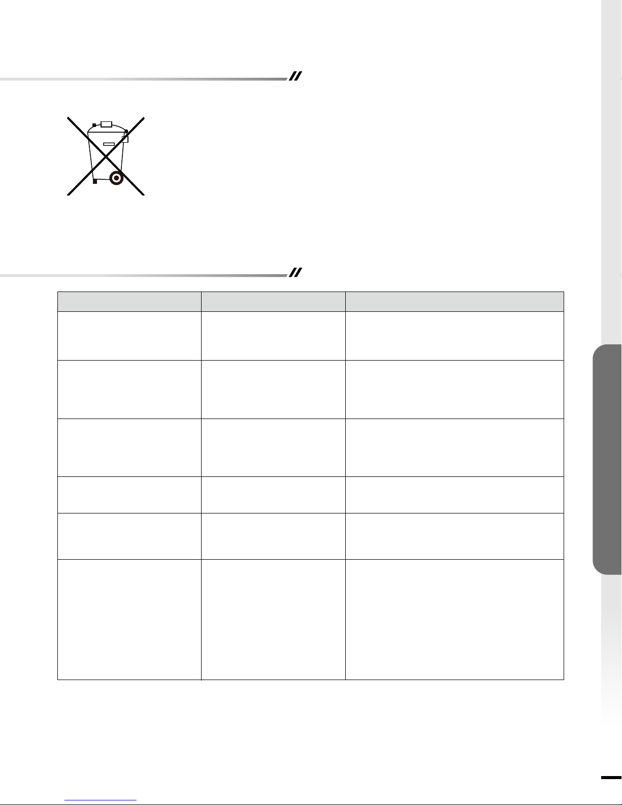
DISPOSAL OF USED BATTERY:
A battery may contain hazardous substances that could be endangering to the environment
and human health.
• This symbol marked on the battery and/or packaging indicates that used battery shall not be
treated as municipal waste. Instead it shall be left at the appropriate collection point for recycling.
• By ensuring the used battery is disposed of correctly, you will help prevent potential negative
consequences for the environment and human health. The recycling of materials will help to
conserve natural resources.
For more information about collection and recycling of used batteries, please contact your local municipality, your waste
disposal service or the point of sale where you purchased this item.
Troubleshooting
Problems
1. No power, logs do not
glow.
2. "E1" is displayed on
control panel.
3. "E2" is displayed on
control panel.
4. "E3" is displayed on
control panel.
5. Fan motor continues
to blow after unit is
powered off.
6. Power cord gets warm
to the touch.
Possible Causes
1. The unit does not have
power.
2. The overheat protection
device has been
engaged.
3. The ambient temperature
sensor is broken or not
working correctly.
4. Child Lock function is
activated.
5. Normal operation.
6. Normal operation.
Solutions
1. Check that unit is plugged into a standard
120 volt outlet. Then make sure power is set
at "ON" position.
2. Unplug unit, wait 5-10 minutes, then the
sensor will reset itself. Plug the unit back
in and turn on the heater. If the problem
persists, call customer service.
3. Unplug unit, wait 5-10 minutes, then the
sensor will reset itself. Plug the unit back
in and turn on the heater. If the problem
persists, call customer service.
4. To inactivate the Child Lock function, hold
the POWER button for 10 seconds.
5. This is a standard feature; the blower runs
for an additional 20 seconds to ensure heat
will not be trapped inside the unit.
6. This is normal for a heater appliance as it
requires more current to operate. Check the
connections of the appliance cord and the
outlet. Make sure the plug fits tightly into
the outlet. During use, check the plug and
outlet frequently to determine if it is HOT;
if so, discontinue use of the appliance and
consult with a qualied electrician to check
or change the overheating outlet(s).
FIREBOX OPERATIONS
15
QUESTIONS, PROBLEMS, OR MISSING PARTS?
Please Contact Customer Service Before Returning to Store
www.soupro.com
Ver. 4
Distributed by Source Pro USA Inc., 26300 SC HWY 121, Whitmire, SC 29178 USA
cs@soupro.com
Crafted in China
+1-800-239-0689
 Loading...