

Page 1
User Manual
1 of 26
PVB-Series
Multi Format LCD Monitor
User Manual
Page 2
User Manual
2 of 26
CAUTION ...................................................................................................................................................... 3
FEATURES ................................................................................................................................................... 5
CONTROLS, INDICATORS AND CONNECTIONS ..................................................................................... 6
MENU BASIC OPERATION ....................................................................................................................... 11
PICTURE MENU ......................................................................................................................................... 13
AUDIO MENU ............................................................................................................................................. 16
DISPLAY MENU ......................................................................................................................................... 17
REMOTE MENU .......................................................................................................................................... 20
SETUP MENU ............................................................................................................................................. 21
INFO MENU ................................................................................................................................................ 23
INPUT SUPPORT MODE ............................................................................................................................ 24
MECHANICAL DIMENSION ....................................................................................................................... 26
Page 3

User Manual
3 of 26
Caution
WARNING:
To reduce the risk of electric shock does not remove cover (or back). No user serviceable parts inside.
Refer servicing to qualified service personnel. To prevent fire or shock hazard, do not expose the rear of
the set to rain or moisture. Do not rub or strike the Active Matrix LCD with anything hard as this may
scratch, mark, or damage the Active Matrix LCD permanently.
Unauthorized tampering with the inside of the monitor invalidates the warranty.
The manufacturer shall not warrant for any damage caused by improper maintenance and/or repair. Work
by third parties.
Important safeguards for you and your new product:
Your product has been manufactured and tested with your safety in mind. However, improper use can
result in potential electrical shock or fire hazards. To avoid defeating the safeguards that have been built
into your new product, please read and observe the following safety points when installing and using your
new product and save them for future reference.
All operating and use instructions should be followed.
The safety and operating instructions should be retained for future reference.
All warnings on the product and in the operating instructions should be adhered to.
Disconnect the unit from the electricity supply before cleaning. Do not use abrasive cleaners. Use a damp
cloth for cleaning.
Do not use this apparatus near water.
A product and cart combination should be moved with care. Quick stops, excessive force and uneven
surfaces may cause the product and cart combination to overturn.
Do not use attachments not recommended by Boland as they may cause hazards.
Do not block any of the ventilation openings.
Install in accordance with the manufacturer’s instructions.
This product should be operated only from the type of power source indicated on the marking label. If you
are not sure of the type of power supply to your home, consult your supplying dealer.
This product is equipped with a three-wire grounding-type cord. This is a safety feature. Do not defeat the
safety purpose of the grounding-type cord.
Power-supply cords should be routed so that they are not likely to be walked on or pinched by items
placed upon or against them, paying particular attention to cords at plugs, convenience receptacles and
the point where they exit from the product.
Before operating the set, please read this manual carefully.
Read Instructions
Follow Instructions
Retain Instructions
Heed Warnings
Cleaning
Water and Moisture
Transporting Product
Attachments
Ventilation
Power Sources
Power Lead Polarization
Power Cord Protection
Outdoor Cable Grounding
Page 4

User Manual
4 of 26
Caution
If an outside antenna or cable system is connected to the product, be sure the antenna or cable system is
grounded so as to provide some protection against voltage surges and built-up static charges. A “face
plate” also needs to be installed with an isolating capacitor to prevent any damage from static.
For added protection for this product during a lightning storm, or when it is left unattended and unused for
long periods of time, unplug it from the wall outlet and disconnect the antenna or cable system. This will
prevent possible damage to the product due to lightning and power-line surges.
An outside antenna system should not be located in the vicinity of overhead power lines or other electric
light or power circuits, or where it can fall into such power lines or circuits. When installing an outside
antenna system, extreme care should be taken to avoid contact with such power lines or circuits, as
contact with them might be fatal.
This product must be earthed properly to comply with the safety regulations in the country of use. If you
are unsure of these regulations, please consult a qualified electrician.
Do not attempt to service this product yourself as opening or removing covers may expose you to
dangerous voltages or other hazards. Refer all servicing to qualified service personnel. If the Set does not
operate properly, switch it off and call your dealer.
Isolate this product from the mains supply and refer servicing to qualified service personnel under the
following conditions:
A. If the power-supply cord or plug is damaged.
B. If the glass front has been damaged.
C. If there is ingress of water between the glass and the LCD screen.
D. If the product does not operate normally by following the operating instructions. Adjust only those controls
that are covered by the operating instructions as an improper adjustment of other controls may result in
damage and will often require extensive work by a qualified technician to restore the product to its normal
operation.
E. If the product has been dropped or the cabinet has been damaged.
F. If the product exhibits a distinct change in performance.
Upon completion of any service or repairs to this product, ask the service technician to perform safety
checks to determine that the product is in proper operating condition and the front seal is intact.
The product should be mounted on a wall only as recommended in the instructions.
This set operates on an AC supply; the voltage is as indicated on the label on the Manual. This appliance
must be earthed at all times through the chassis as well as through the power lead.
Lightning
Power Lines
Earthing the product
Servicing
Damage Requiring Service
Safety Check
Mounting
Power
Page 5

User Manual
5 of 26
Features
This product is the multi-format Digital LCD Panel to display various kinds of digital video input signal as
HD/SD-SDI/DVI/HDMI Digital and analog signal such as Composite/S-Video/RGB/PC-RGB/ Component.
This is also High Definition Broadcasting Monitor which can make it available to do output of stable video
signal with the menu of considering convenient user interface and the easy control for brightness and
color.
• HD/SD SDI 2INPUT/2 OUTPUT.
• WAVEFORM / Vector Scope / Time code Display.
• 16 ch Audio Lever Meter Display. (SDI only/)
• Analog & Digital Signal Audio Lever Meter Display.
- Lever Meter Position display selectable
• Dual Link MODE & 1080p 60 Compatible
• Closed Caption (Analog Signal only): CEA608, 708
• H/V Delay.
• Audio Disembedder & Internal Speaker & Headphone out & Monitor out
• Color Temperature – User, VAR, 11000K, 9300K, 6500K, 5400K, 3200K
• Over Scan/Zero Scan/Under Scan/Pixel to Pixel
• PIP (Picture In Picture)/PIP Blend
• Tally LED function (Green/Red/AMBER)
• Integrated DVI (HDCP) function.
• HDMI (HDCP) function.
• Supports VESA DDC2B and a subset of VESA standards.
• Single board is suitable for mounting behind an LCD panel.
• Supported RS-232C, RS-422.
• Supported External GPI Control (RJ-45).
• OSD: Graphic based OSD, 6 Languages (UNICODE System).
• LCD Dimming Control
- Manual Dimming Level Control.
• UMD
• Auto Calibration: CA-210,CA-310(Minolta) / K-10(Klein)
• ETHERNET: Network System Controller / Update
Page 6
User Manual
6 of 26
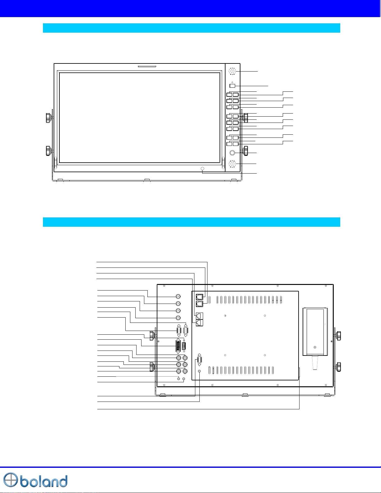
Controls, Indicators and Connections
STANDBY
SDI1
SPEAKER_L
SDI2
HDMI DVI
Composite
SCAN
MARKER
H/V DELAY
AUDIO WF/VT
F1 F2
MENU
UP
ENTER/INPUT
DOWN
ADJUST
SPEAKER_R
IR
SDI 1 OUT
CVBS2/Y/G/Y IN
CVBS3/Pb/B/C IN
CVBS1/Pr/R IN
DVI
HDMI
RS-232 OUT
RS-232 IN
SDI 2 OUT
SDI 2 IN
SDI 1 IN
CVBS1/Pr/R OUT
CVBS2/Y/G/Y OUT
CVBS3/Pb/B/C OUT
AUDIO OUT
AUDIO IN
HEADPHONE
RS422 IN
RS422 OUT
ETHERNET
GPI
DC 12V
LAN UPDATE
PVB17 Front
PVB17 Rear
Page 7
User Manual
7 of 26
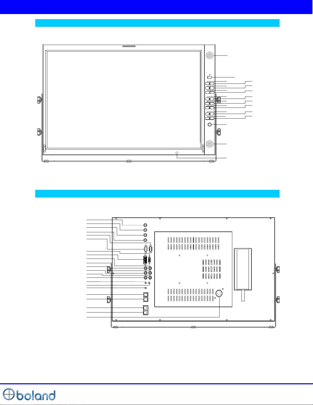
Controls, Indicators and Connections
STANDBY
SDI1
SPEAKER_L
SDI2
HDMI DVI
Composite
SCAN
MARKER
H/V DELAY
AUDIO WF/VT
F1 F2
MENU
UP
ENTER/INPUT
DOWN
ADJUST
SPEAKER_R
IR
SDI 1 OUT
CVBS2/Y/G/Y IN
CVBS3/Pb/B/C IN
CVBS1/Pr/R IN
DVI
HDMI
RS-232 OUT
RS-232 IN
SDI 2 OUT
SDI 2 IN
SDI 1 IN
CVBS1/Pr/R OUT
CVBS2/Y/G/Y OUT
CVBS3/Pb/B/C OUT
AUDIO OUT
AUDIO IN
HEADPHONE
DC 12V
RS422 IN
RS422 OUT
ETHERNET
GPI
PVB24 Front
PVB24 Rear
Page 8
User Manual
8 of 26
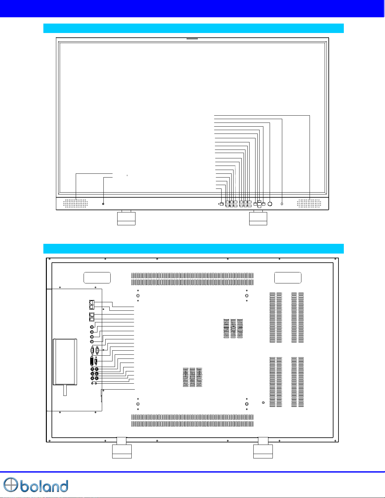
Controls, Indicators and Connections
MARKER
ADJUST
SPEAKER_R
F2
H/V DELAY
SCAN
SDI1
HDMI
Composiet
AUDIO
DOWN
IR
ENTER/INPUT
UP
MENU
F1
WF/VT
SDI2
STANDBY
DVI
HEADPHONE
SPEAKER_L
CVBS3/Pb/B/C OUT
RS-232 OUT
DVI-I
SDI 2 IN
SDI 1 IN
RS422 OUT
AUDIO IN
AUDIO OUT
CVBS3/Pb/B/C IN
CVBS2/Y/G/Y IN
SDI 2 OUT
RS-232 IN
HDMI
CVBS1/Pr/R OUT
CVBS1/Pr/R IN
CVBS2/Y/G/Y OUT
SDI 1 OUT
GPI
ETHERNET
RS422 IN
DC 24V IN
PVB47 Front
PVB47 Rear
Page 9

User Manual
9 of 26
Controls, Indicators and Connections
Front Keys Arrangements
STANDBY
Power ON/OFF Button. This button is operated after being pressed about 3 seconds.
SDI 1 / SDI 2
Select SDI 1/ SDI 2 source directly
HDMI
Select HDMI source directly
DVI
Select DVI source directly
Composite
Select ANALOG source directly ( ‘CVBS1’ ->‘CVBS 2’ ->‘CVBS 3’)
MARKER
Draw Marker on Screen (Off -> 16:9 -> 4:3 … -> 2.35:1)
H/V-DELAY
Activates ‘H & V' blanking display ‘H DELAY’ -> ‘V DELAY -> ‘HV DELAY’ -> OFF
AUDIO
Activates Audio Lever Meter
WF/VECTOR
Activates WAVRFORM & Vector Scope (SDI Only)
Setup Menu Waveform format selecting
FUNCTION 1 ~ 2
Executes functions of user selected
(UNDEF, Aspect, Mono/Blue, Audio Group/Channel/Mute, Time code, Still image,
Caption, Aspect Marker, Area Marker, PIP func & Input, Zoom, Gamma Select, WFM Line Select.)
MENU
Activates main OSD menu
Navigates higher menu in main OSD menu
Exits OSD menu
DOWN
Decreases sound volume of speaker
Decreases values of user menu in main OSD menu
Executes function (by OSD help commands) in main OSD menu
UP
Increases sound volume of speaker.
Increases values of user menu in main OSD menu
Executes function (by OSD help commands) in main OSD menu
SEL/INPUT
Activates OSD menu of input source selecting
Changes input source by selecting
Executes functions (by OSD help commands) in main OSD menu
Activates child menu
ADJUST
Adjust Picture Menu (Brightness -> Contrast -> Color -> Sharpness->Phase & Tint)
Turn Right (with ‘UP' button is same)
Turn Left (with ‘DOWN' button is same)
Page 10
User Manual
10 of 26
Controls, Indicators and Connections
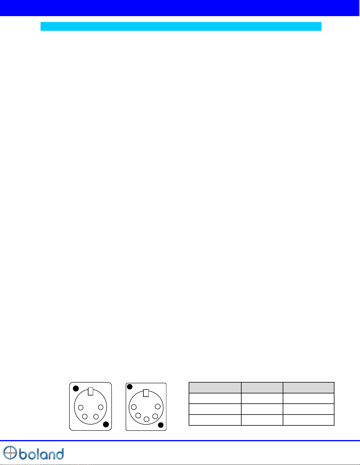
PIN NO(4P_12V)
Description
PIN NO(5P_24V)
1
GND
1 ,2
2 , 3 4 4
+ 12V/+24V
4 , 5
1 2 3
4
1
2
3
4
5
REAR Panel
SDI 1/SDI 2 IN
HD SDI / SD SDI Input
SDI 1/SDI 2 OUT
SDI 1, SDI 2 Loop Out
RS-232C IN
Update /Auto color calibration
DVI-I
DVI-I Type Digital / Analog PC-RGB Video Input
HDMI
High Definition Multimedia Input
CVBS1/Pr/R In
CVBS 1, Component Pr, GBR(SOG sync) R Input
CVBS2/Y/G/Y In
CVBS 2, Component Y, GBR(SOG sync) G, S-Video Y Input
CVBS3/Pb/B/C In
CVBS 3, Component Pb, GBR(SOG sync) B, S-Video C Input
AUDIO IN
DVI-I/Component/GBR/CVBS1,2,3/S-Video Sound Input
AUDIO OUT
AUDIO MONITOR OUT
ETHERNET
Network System Control/ Firmware Upgrade
GPI
GPI 1 ~ 7 Control Port
RS422 IN/OUT
Monitor System Control
HEADPHONE
Headphone output
DC 12V/24V IN
Page 11
User Manual
11 of 26
MENU Basic Operation
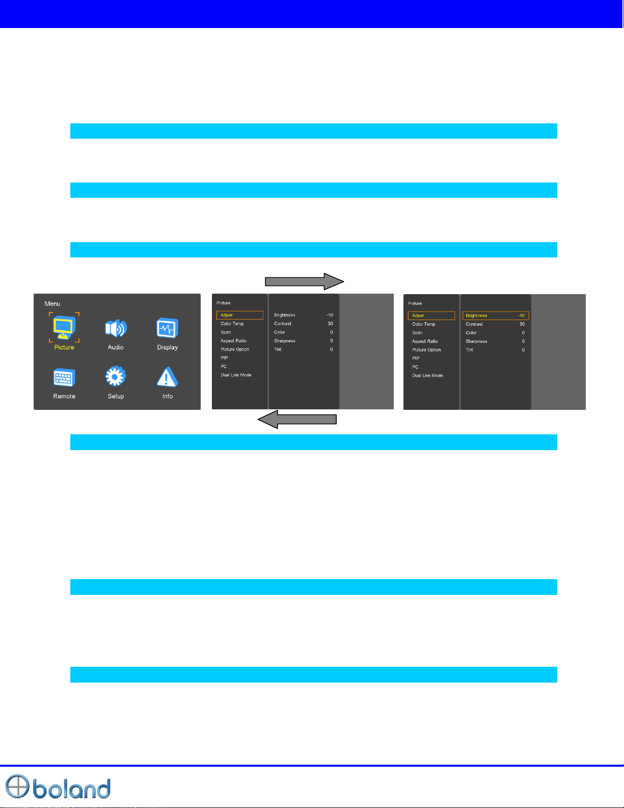
In this menu system, there are several ways to customize the menu settings provided.
Most menus consist of three levels to set up the options, but some require greater depth for the variety of
settings. If you press the MENU button, only the first and second level of the menu system will appear on
the monitor screen. The third level can be displayed by pressing SEL/INPUT. If a menu has more than
three levels, the pop-up dialogue box will be displayed as the fourth or fifth level.
To show and remove the Menu
Press the MENU button to display the menu. A second press of the MENU button will take you back to
monitor viewing.
To go to the next level
Press SEL/INPUT button.
To go back to the previous level
Press MENU button
Typical Menu Operation
1. Press MENU button: The main menu will appear.
2. Use Adjust / Take button Turn Right/ Left to select the desired menu option (icon).
3. While the desired menu option is selected, press SEL/INPUT to move to the second level.
4. Use Adjust / Take button Turn Right/ Left to select the second menu option.
5. Press SEL/INPUT to move to the third level: Some menu options require additional steps.
6. Press MENU to return to the previous menu to return to monitor viewing.
Turning On the Monitor
1. First, connect power cord correctly. At this moment, the monitor switches to standby or power on mode.
In standby mode, in order to turn monitor on, press the ST-BY button.
2. Select the viewing source by using SEL/INPUT button on Keypad in front of monitor
Volume Adjustment
1. Press the Adjust / Take button Turn Right/ Left button on Keypad.
2. If you want to switch the sound off, press the FUNCTION (Audio mute) button.
3. You can cancel this function by pressing the FUNCTION (Audio mute) or volume control button.
Page 12
User Manual
12 of 26
MENU Basic Operation
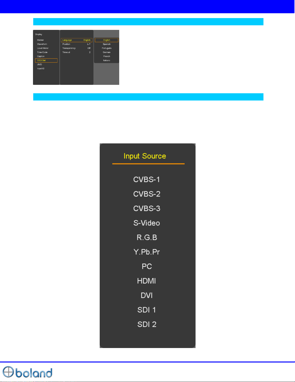
On Screen Menus Language Selection
- Display -> OSD Set -> Language
- The menus can be shown on the screen in the selected
language.
- Supported Language: English, Spanish, Portuguese, German,
French, Italian
How to Select Video Source by OSD
1. Press the SET/INPUT button and then UP/DOWN button to select each video source.
2. Press the SET/INPUT button to go to desired video source.
3. If Input Name is enabled, The SET/INPUT button goes into input name edit mode instead of selecting
source.
Page 13
User Manual
13 of 26
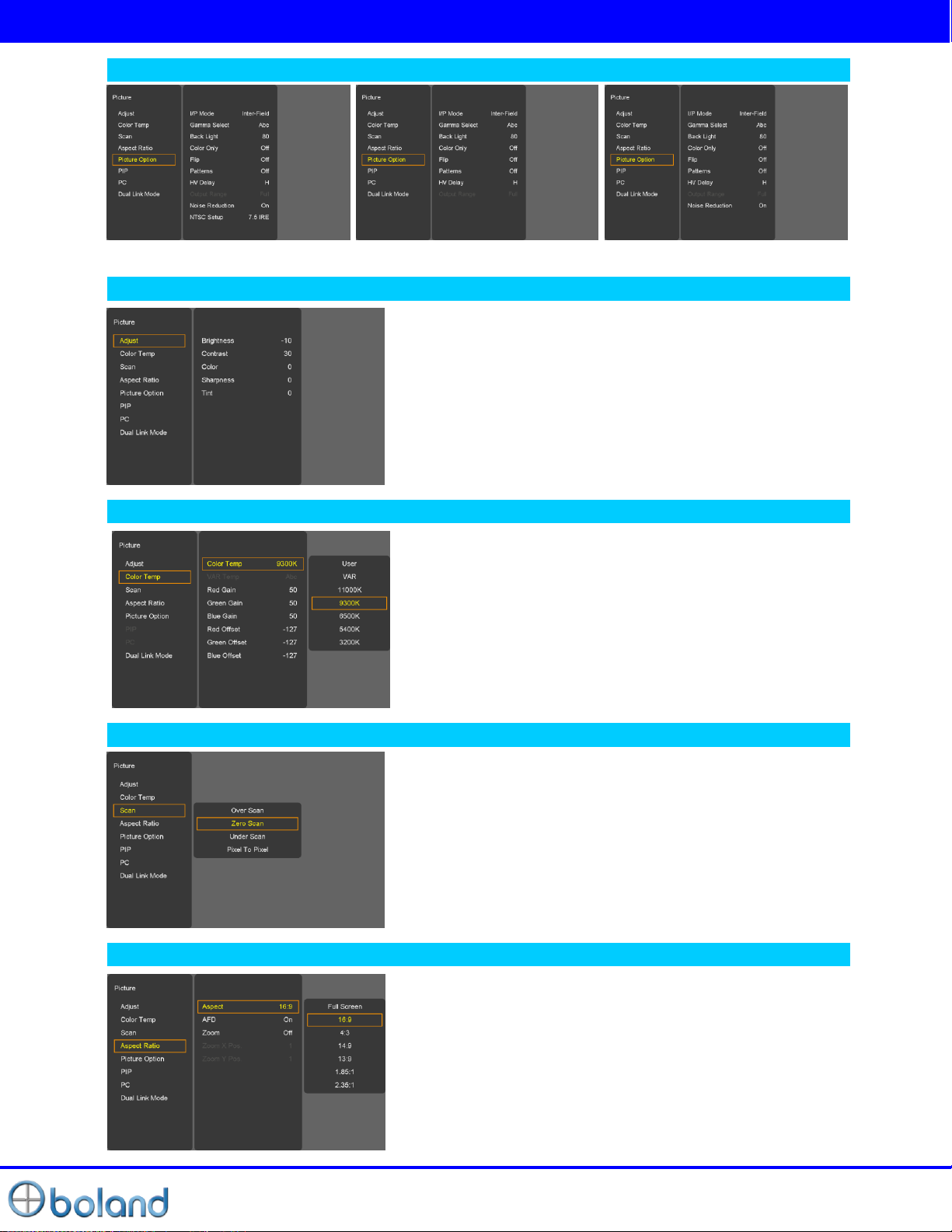
PICTURE MENU
Video Menus of each Input modes
< Video (NTSC) Picture menu> < PC Picture menu> < SDI, HDMI Picture menu>
Adjust
- Adjust the values of Brightness, Contrast, Color, Tint and
Sharpness directly from -50 to 50
Contrast, Brightness, Sharpness, Color (All Sources), Tint
(without PC, DVI, HDMI, Component), Phase (Component).
Color Temp
SCAN
Aspect
- For Setting the Color temperature or adjusting RGB
Gain/Offset value directly
- User (User setting RGB gain value), VAR(3200K ~ 11000K),
Often used value(11000K, 9300K, 6500K, 5400K,3200K)
1. Over Scan – 95% input size and fit the selected display size
2. Zero Scan – 100% Input size and fit the selected display size
3. Under Scan – 105% Input size and fit the selected display
size
4. Pixel to Pixel – Display size is an input size. If input resolution
is bigger than panel size, fit the panel size
- For setting the aspect ratio.
- Full Screen: The images are displayed with a panel size.
- Full Screen, 16:9, 4:3, 14:9, 13:9, 1.85:1, 2.35:1: The images
are displayed with each aspect ratio.
- PC mode: Full Screen & 4:3 only
-AFD (Active Format Description): If this mode is selected, the
embedded Aspect ratio signal in the video signal will be
extracted and displayed as a marker.
Page 14
User Manual
14 of 26
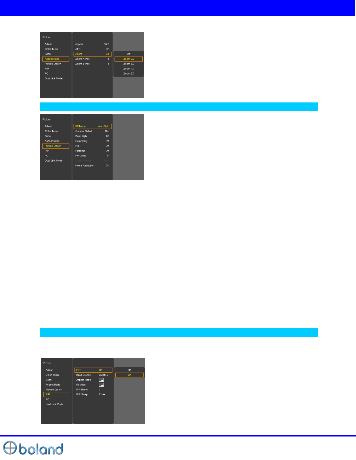
PICTURE MENU
ZOOM
Picture Option
Color Only
Mono Color/Blue only Function on/off
- Mono color: For selecting monochrome images.
- Blue Only: Images have only blue color expect red and green color
Flip
H-Flip Function on/off
Patterns
Auto Run, 100% Color Bars, 75% Color Bars, Luma, RGB, White, Black, RED, Blue, Green
HV Delay
Off / H / V / H+V
Output Range
Normal (16~235)/Full (0~255)
Noise Reduction
-Noise Reduction on/off. (NR is for Video signal (HD-SDI, CVBS, S-Video and Y.Pb.Pr) & DTV timing.
NTSC Setup
- IRE value under NTSC mode between 0 IRE and 7.5 IRE.
- Can see the enlarged picture by (2X, 3X, 4X, 5X) ratios.
- If user select the Zoom 2X, can see the below yellow box in
picture.
- Press Select or Enter button, user can see the enlarged
picture.
- Menu key escape the zoom mode.
I/P Mode
Line Doubler/inter-Field/Field Merge function on/off
Gamma Select
Gamma Level Select (0.8 ~ 3.0)
Back Light
Inverter dimming Level select (0~100)
PIP (Picture IN Picture)
- Watch two programs or source at the same time. And set up PIP size and position.
PIP ON/OFF
- Control PIP function On/Off.
Page 15
User Manual
15 of 26
PICTURE MENU
SDI 1
SDI 2
HDMI-DVI
PC_YPbPr_RGB_YC_CVBS
SDI 1
X O O
O
SDI 2
O X O O HDMI-DVI
O O X
O
PC_YPbPr_RGB_YC_CVBS
O O O
X
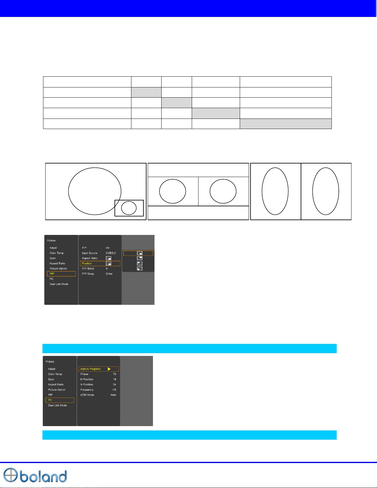
PIP
POP1
POP2
Input Source
- PIP input Source can operate with different signal and type.
- Analog (CVBS 1, 2, 3, Y.Pb.Pr, GBR, PC) inputs + Digital (DVI, HDMI) + SDI (SDI1, SDI2) inputs
-SDI + SDI input PIP
Ex) AV + S-Video (X), DVI + SDI (O), PC + DVI (O), SDI1+SDI2 (O)
- PIP MATRIX TABLE
Aspect
- Choose PIP size of Small/POP1/POP2
Position
PIP Swap
- Using Swap option, you can exchange two programs or source at the same time.
-
Choose the pip position on the each corner of the pane
PIP Blend
-Blend to PIP size of Small
PC Menu
Dual Link Mode (SDI only)
-Dual Link Mode select. (Auto/Off/RGB444/YCbCr444/YCbCr422/Progressive)
- Only operate PC input mode
- Select Auto-adjust and adjust Phase, HV position, Frequency
- Auto-Adjust automatically set the optimum values of Phase,
HV position and Frequency.
-Selects X768 native PC video timings.
(Auto/1024x/1280x/1360x/1366x)
Page 16
User Manual
16 of 26
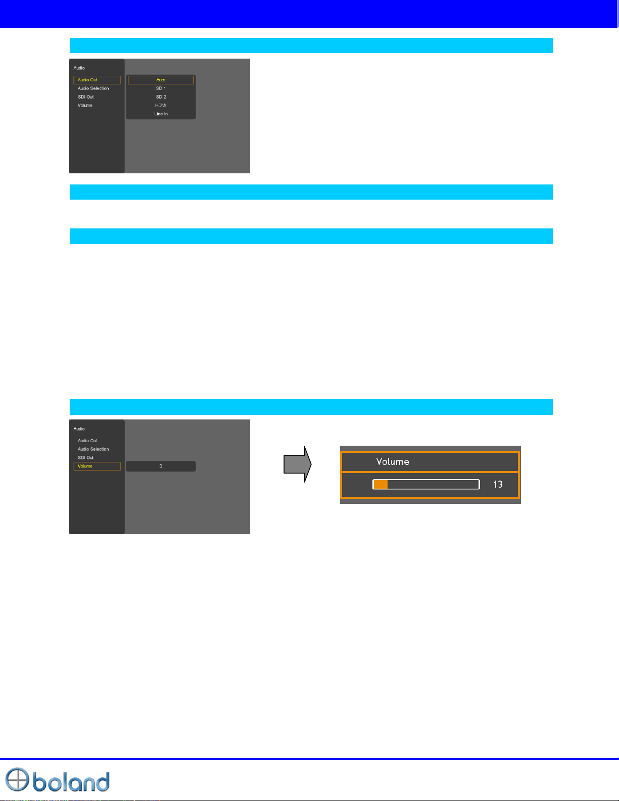
AUDIO MENU
Audio out
Audio Selection
-PIP & W/F Double mode only. Select the Main or Sub.
SDI out
-SDI Audio output Group & Channel source select
SDI Gr/Ch
- Audio output Group source select. (Group1, 2, 3, 4)
- Audio output Channel source select. (Channel1~16, Channel1/2,3/4,5/6,7/8,9/10,11/12,13/14,15/16 off)
SD2 Gr/Ch
- Audio output Group source select. (Group1, 2, 3, 4)
- Audio output Channel source select. (Channel1~16, Channel1/2,3/4,5/6,7/8,9/10,11/12,13/14,15/16 off)
- Select Internal Speaker out. (Auto/SDI1/SDI2/HDMI/Line in)
Volume
- Adjust the speaker or headphone Volume level.
Page 17
User Manual
17 of 26
DISPLAY MENU
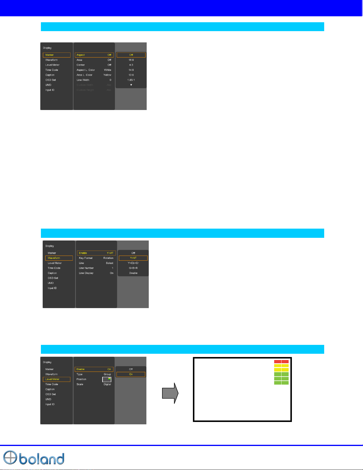
Marker
Aspect
Area
- Area: Draw dotted line Marker on screen in case of images. (16:9 95/93/90/88/80%, 4:3
95/93/90/88/80%, EBU Action 16:9/14:9/4:3, EBU Graphic 16:9/14:9/4:3)
Center Maker
- “+” Marker on center of screen
Aspect L. Color
-Marker Line Color Select. (WHITE, YELLOW, BLUE, RED, BLACK)
Area L. Color
-Area Line Color Select. (WHITE, YELLOW, BLUE, RED, BLACK)
Line Width
- Marker line thickness setting. (0~10)
Custom Marker
-The user wants Marker size setting. (Below panel size)
- 16:9, 4:3, 14:9, 13:9, 1.85:1, 2.35:1, 1.85:1&4:3, Custom fitted
panel size marker on screen.
Waveform
Enable
- Off / Y+VT / Y+Cb+Cr/ G+B+R /Double
Key Format
- Press the W/F button to display the WAVEFORM Mode.
(Rotation, Y+VC, Y+Cb+Cr, G+B+R, Double)
Line Select
- Select line WAVEFORM & Vector Scope display.
Line Number
-Line select: Input Resolution size.
Line Display
-off/on/5 sec
Level Meter
- Display the audio level meter on screen in SDI input.
- Audio level meter cannot display with OSD.
Page 18
User Manual
18 of 26
DISPLAY MENU
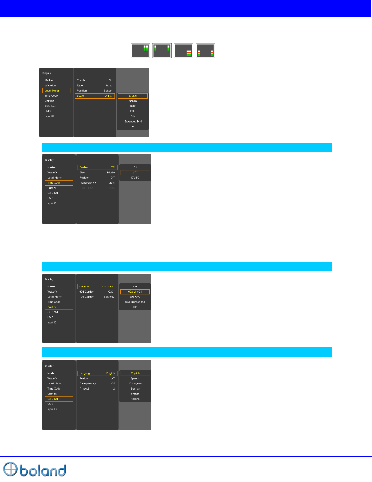
Type
-Pair: Respectively Channel with right and left display
-Group: Respectively group display
Position
- Level Meter Position selects. ( )
Scale
Time code
- Disable blending Time code background with video image. (0%, 25%, 50%, 75%, 100%)
DVITC Line
-Auto, Line 1 ~ 31
- Level Meter Scale mode selects.
(Digital/Nordic/BBC/EBU/DIN/Expanded DIN/SMPTE VU/EBU
VU/France VU)
Enable
- Time code Display (off/LTC/DVITC, SDI only)
Size
-Time code size select. (Small, Middle, Large)
Position
- Time code display position selects (L-T, C-T, R-T, L-B, C-B, RB)
Transparency
Caption
OSD Set
- OSD gone time setting. (3~200)
Caption
-608 Line21, 608 ANC, 608 Transcoded, 708 mode Select
608 Caption
-608 Caption mode Select. (C/C1, C/C2, C/C3, C/C4, TEXT1,
TEXT2, TEXT3, TEXT4, OFF)
708 Caption
-708 Service mode Select. (Service 1/Service 2)
Language
-Select a language for the menus to appear in. (English,
Spanish, Portuguese, German, French, Italian)
Position
- L-T, R-T, C, L-B, R-B
Transparency
- Disable blending OSD background with video image.
Timeout
Page 19

User Manual
19 of 26
DISPLAY MENU
UMD
Channel-01
Tally Red
Channel-01
Tally Green
Channel-01
U.M.D
UMD
- UMD display on/off
Character
- UMD Character Select
Position
- UMD display position select. (L-T, C-T, R-T, L-B, C-B, R-B)
FG Color
- UMD Character color Select (RGB_255_192_128_0_Transpareut)
BG Color
- UMD BG color Select (RGB_255_192_128_0_Transpareut)
Input I.D.
Input ID
- source Message display.
ID Style
- select “Input Format”/”Custom Label”
Input Label
- Display user made name instead of input source name on source OSD and message OSD.
Page 20
User Manual
20 of 26
Remote MENU
GPI Function
Description
Undefined
Not set (no function allocated)
Marker1 On/Off, Marker2 On/Off
Displays the markers which have been set by the
GPI PRESET1, 2 items on the screen.
Center Marker
Displays the center marker.
Safety Area
Displays the Safety Area.
Tally R, Tally G
For lighting up the Red or Green tally lamp.
Scan
Over Scan/Zero Scan/Under Scan/ Pixel to Pixel
Input CVBS 1,2,3, Input G.B.R, Input SDI
1, Input SDI 2, Input Y.Pb.Pr , Input PC ,
Input DVI, Input HDMI
Switches the input source.
Menu Key, Enter Key, Up Key, Down Key
Left Key, Right Key
Use the key function by GPI.
Function 1, Function 2
Activates FUNCTION 1, 2 buttons
Aspect
Sets the aspect ratio of the images
Waveform
Activates WAVRFORM & Vector Scope (SDI
Only)
GPI 7 : Power Key(Fixed)
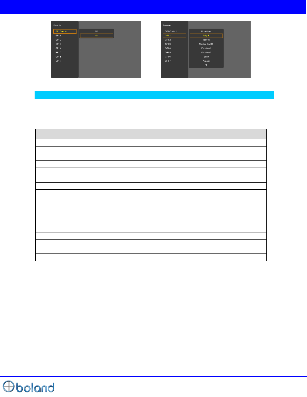
GPI Control & GPI#
- For allocating functions to particular GPI pins.
- When remote control operations are to be performed using the GPI Controller.
- GPI Control: GPI function Enable/Disable
- GPI 1 ~ 7
Page 21
User Manual
21 of 26
SETUP MENU
Function1&2 button
Description
Undefined
Not set (no function allocated)
Aspect
Sets the aspect ratio of the images
Mono/Blue
Execute Mono color or Blue Only
Audio Group
Select the extract the embedded audio group in SDI input.
Audio Channel
Select the extract the embedded audio channel in SDI input.
Time Code
Time Code on/off.
Audio mute
Toggles sound status of speaker/headphone in mute.
Still image
Toggles picture status between motion and still image.
Caption
Caption on/off.
Flip
H-Flip Function on/off
Aspect Marker
Aspect Marker Select
Area Marker
Area Marker Select
Marker Preset
Displays the markers which have been set by the GPI PRESET1, 2
items on the screen.
PIP func & Input
PIP func & input Select
Zoom
Zoom function on/off
Gamma Select
Gamma Select
WFM Line Select
WFM Line select function on/off
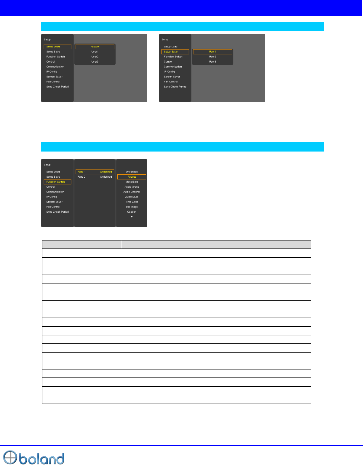
Setup Load & Setup Save
- Setup Load: Load user saved values or default value
- Setup Save: Save user setting values at user 1, 2, 3.
Function Switch
- Function 1, 2: Select the function to be allocated to the FUNCTION 1, 2 buttons
Page 22
User Manual
22 of 26
SETUP MENU
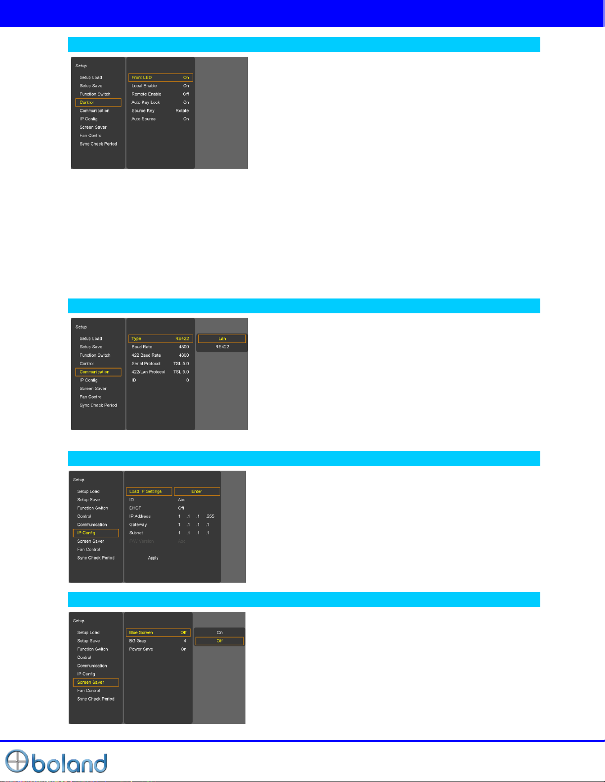
Control
Auto Key Lock
- If it does not work 10 minutes to lock automatically. Key button is operated after being pressed about 2
seconds
Source Key (Front “Input Button / Remote Controller “Source” Button)
-Menu: Select the input signals to the input menu OSD.
-Rotate: Press Button to rotate the input source.
Auto Source
- When there is no input signal, Auto Source change.
Front LED
- Front LED on/off
Local Enable
-Power, up and down key is only worked, if Local enable is off.
Remote Enable
- Select the controller of local or remote. If remote controller is
selected, both local (front key) and remote are worked.
However select local, local key only operated.
Communication
IP Config
Type
-Select the Communication: RS-422 or Lan
Baud Rate _ 422 Baud Rate
- 2400/4800/9600/19200/38400/57600/115200
Serial Protocol_422/Lan Protocol
-Basic / TSL 5.0 / TSL 4.0 / RDU/ Extension
ID (01~99)
- If control each Board, must set ID numbers of each Board
Load Network Settings: ETHERNET cable connected after
“Enter”. (ID/IP Address/Gateway/Subnet Load)
DHCP: DHCP on/off (Manual IP settings – DHCP on)
* “Apply” enter all settings after.
Screen Saver
Blue Screen
- Enables screen saver functions to avoid panel burning.
BG Gray
- Select gray level on besides display picture. (0~7)
Power Save
- DPMS (Display Power Management Signaling) Power Save
Mode.
Page 23
User Manual
23 of 26
SETUP MENU
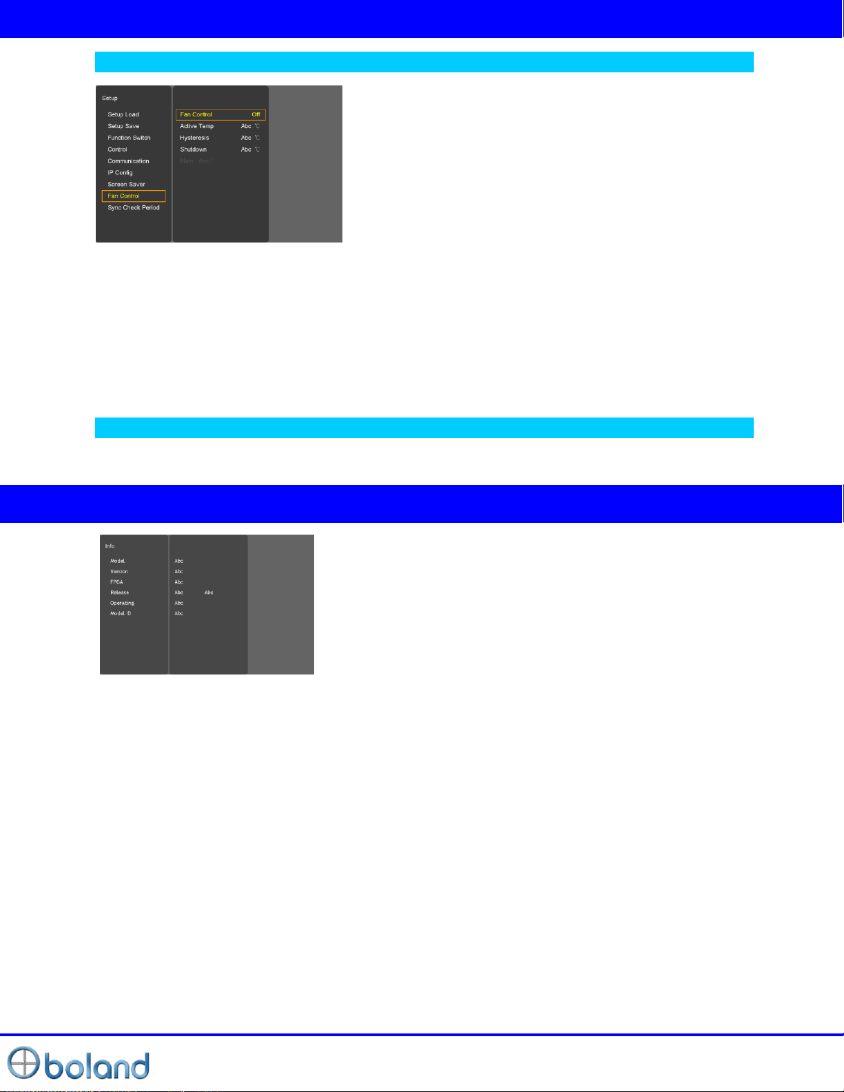
Fan Control
Fan Control
- Internal Fan Controls driving option by temperature sensor Auto / force on / force off
Active Temp
- Adjusts fan driving temperature by Celsius degree. It works only when the Fan Control setting is Auto.
Hysteresis
- Adjusts fan driving hysteresis temperature by Celsius degree. (1~10℃)
Shutdown
- For a monitor protection is above of 75℃, Power Off.
Sync Check Period
- Sync Check Period at when switching the input signal (10 ~ 300 ms)
Info MENU
- Model, H/W Version, FPGA, F/W Release, Operating Time, Cal. ID
Page 24
User Manual
24 of 26
Input Support Mode
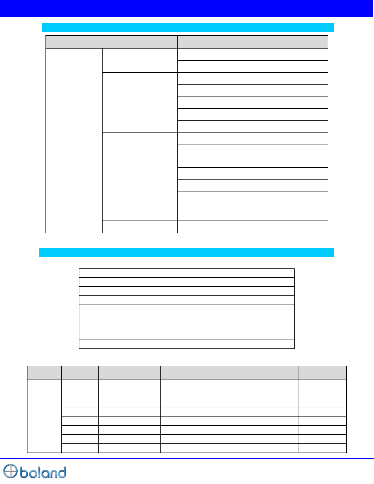
Items
Specifications
Supported
Signals
Serial Digital Interface
HD SDI- 2.970Gbps
SD HDI- 270Mbps
HDMI
DVI-I (DVI+VGA_IN)
H Frequency Range : 20~82 kHz
V Frequency Range : 55 ~ 90 Hz
Maximum resolution :1920x1080 60Hz
Maximum pixel rate : 162 MHz
DTV mode support : 720P, 1080i, 1080p
ANALOG RGB
H Frequency Range : 20~82 kHz
V Frequency Range : 55 ~ 90 Hz
Maximum resolution : 1920x1080 60Hz
Maximum pixel rate : 162 MHz
DTV mode support: 720P/1080i/1080p
SOG sync support
ANALOG Component
(DTV/DVD)
1080p/1080i/720P/480i/576i/480P/576P
CVBS
NTSC/PAL/SECAM
SMPTE-428.1M
2048x1080P(24/25)
SMPTE-425M(3G)
1920x1080P(50/60)
SMPTE-260M
1920x1035i(60/59.94)
SMPTE-259M
1920x1080i(50)
SMPTE-274M
1920x1080i (50/59.94/60)
1920x1080P (30Psf/25Psf/24Psf/30/25/24)
SMPTE-296M
1280x720P (24/25/30/50/59.94/60)
SMPTE-125M
480i(59.94)
ITU-R BT.601
576i(50)
Section
Resolution
H Frequency( kHz )
V Frequency( Hz )
Pixel Frequency( MHz )
Comment
PC
640x400
37.861
85.08
31.5
640x350
31.469
70.087
25.175
640x350
37.861
85.08
31.5
640x480
31.469
59.94
25.175
640x480
35.000
66.667
30.24
640x480
34.940
69.884
28.513
640x480
37.861
72.809
29.765
640x480
37.500
75.0
31.5
Supported Signals
Supported Timings
SDI input
PC & DVI input
Page 25
User Manual
25 of 26
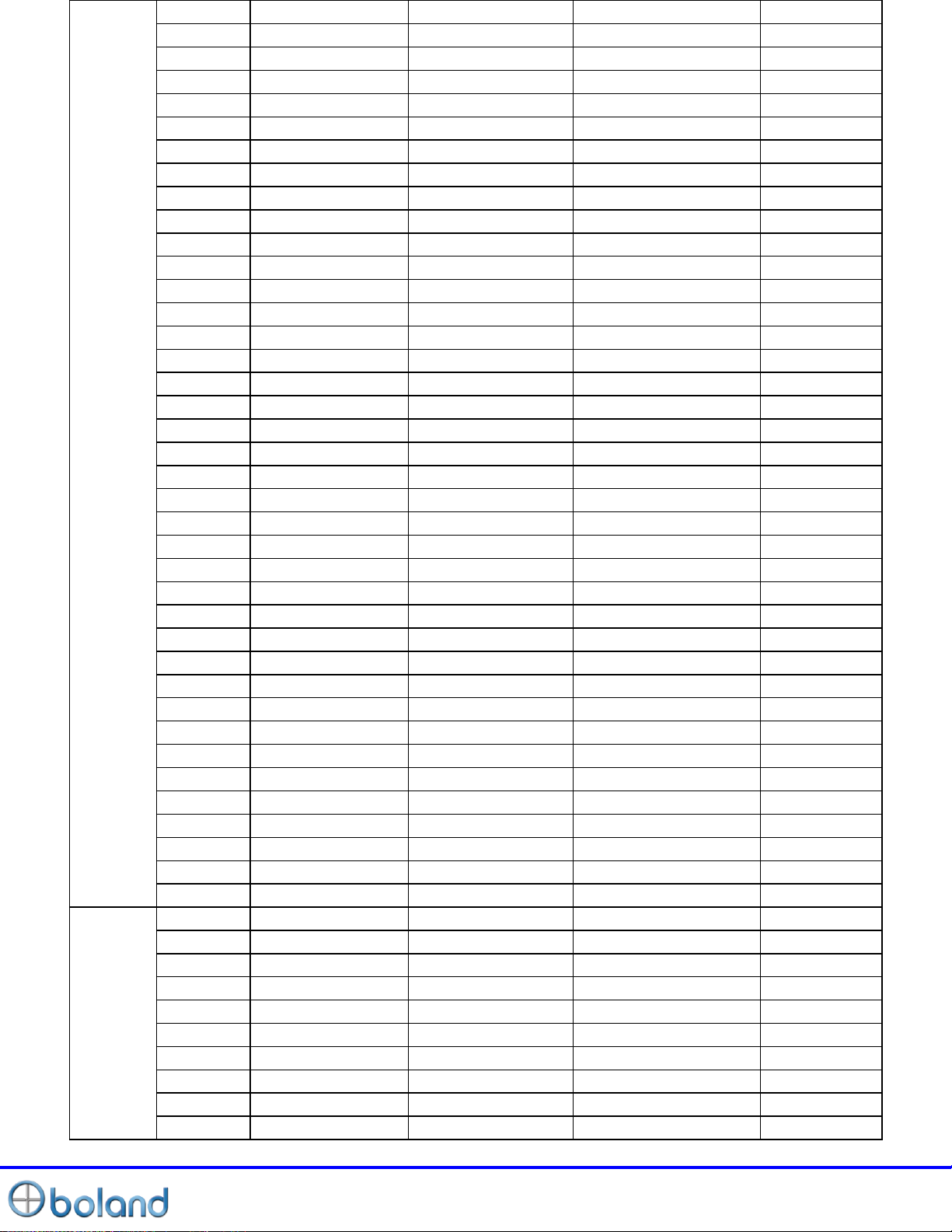
640x480
43.269
85.008
36.0
640x480
45.540
90.0
37.889
720x400
31.469
70.087
28.322
720x400
37.927
85.039
35.5
800x600
35.156
56.25
36.0
800x600
37.879
60.317
40.0
800x600
43.764
70.02
45.513
800x600
48.077
72.188
50.0
800x600
46.875
75.0
49.5
800x600
53.674
85.061
56.25
800x600
56.880
90.0
60.065
832x624
49.726
74.551
57.284
1024x768
48.780
60.001
64.11
1024x768
48.363
60.004
65.0
1024x768
56.476
70.069
75.0
1024x768
57.703
72.039
78.476
1024x768
60.241
74.927
81.724
1024x768
60.030
75.029
78.75
1024x768
68.677
84.997
94.5
1024x768
72.810
90.0
100.187
1152x864
53.700
60.0
81.624
1152x864
62.932
69.924
96.663
1152x864
67.500
75.0
104.993
1152x870
68.681
75.062
100.0
1152x900
61.846
66.0
94.787
1152x900
72.713
76.047
105.561
1280x720
47.760
60.0
74.481
1280x720
52.500
70.0
89.040
1280x720
54.072
72.0
91.706
1280x720
56.400
75.0
95.654
1280x768
60.150
75.0
102.977
1280x960
60.000
60.0
102.104
1280x960
59.640
60.0
102.104
1280x1024
63.337
59.978
108.18
1280x1024
63.981
60.02
108.0
1280x1024
64.754
60.06
108.992
1280x1024
63.600
60.0
108.883
1360x768
47.700
60.0
84.700
1600x1200
75.000
60.0
162.000
DTV
720x480
15.735
59.94
13.500
Interlaced
720x576
15.735
50.0
13.595
Interlaced
720x480
31.469
59.94
25.175
720x576
31.250
50.0
26.566
1280x720
44.964
59.94
74.176
1280x720
37.500
50.0
60.466
1920x1080
33.750
60.0
74.25
Interlaced
1920x1080
28.125
50.0
70.723
Interlaced
1920x1080
31.250
50.0
72.000
Interlaced
1920x1080
67.5
60
148.5
Progressive
Page 26
User Manual
26 of 26
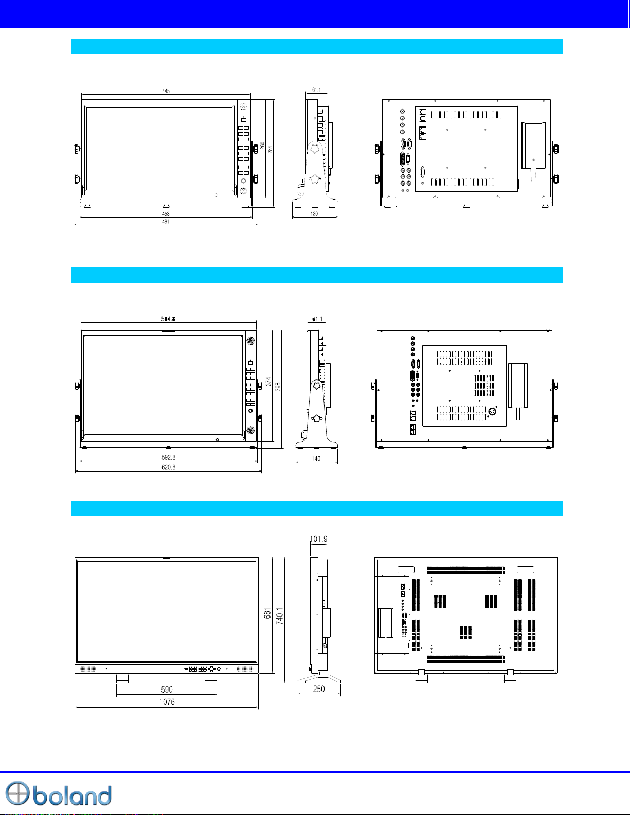
Mechanical Dimension
PVB17
PVB24
PVB47
 Loading...