

Page 1
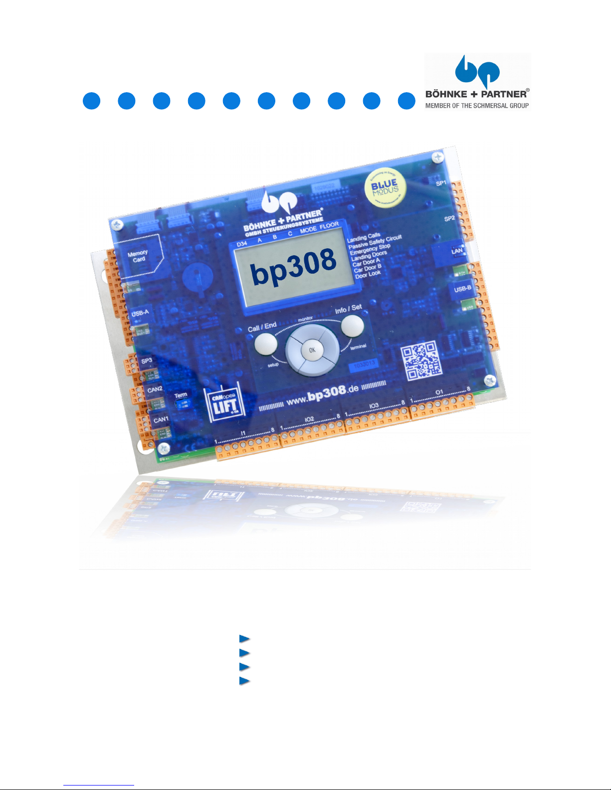
System »bp308«
General Information
Safety instructions
Commissioning
EC-Type Examination
www.boehnkepartner.de
Installation Manual
Page 2

© BÖHNKE + PARTNER
Member of the Schmersal Group
Bergisch Gladbach 2014
1. Intermediate result of the first edition 2014
Installation Manual System »bp308«
February 2014
Author: Development Department
Proof reading: Development Department
Type setting: Development Department
Created using OpenOfficeOffice 4.0
This Installation Manual is in its entirety copyrighted. All rights, especially the rights of translation, presentation, reproduction, copying, using photo mechanical or other way, and storage in electronic media.
This manual does not provide information about our entire product options.
Regardless of the care that has been used for the creation of text, illustrations, and pro-
grams, we can not take responsibility for possible errors or the consequences of a legal liability.
The data presented in this work, names, trade names, trademarks, etc., may be trademarks
and are subject to statutory provisions even if not explicitly.
® BÖHNKE + PARTNER, BlueModus®, WinMOS®300 and CANwizard® are registered trademarks.
www.boehnkepartner.de
Page 3

Table of Contents
1 General Information .......................................................................................................7
1.1 Many Thanks .............................................................................................................. 7
1.2 Purpose........................................................................................................................ 8
1.3 Documentation............................................................................................................8
2 Safety Information...........................................................................................................9
2.1 Qualified Personnel.................................................................................................... 9
2.2 Safety Instructions Concerning Control Units ........................................................9
2.3 Assembling and Operating Requirements..............................................................11
3 Product Certifications .................................................................................................13
3.1 General Description .................................................................................................13
3.2 EC Type Test Certificate BPL 02 with SMZ............................................................14
3.3 EC Certification bp308
(95/16E/G): 01/208/5A/1103/1644Ae5................................................................................. 17
3.3.1 Declaration of Conformity with EC Directive
(95/16/EG).................................................................................................................................. 17
3.3.2 Declaration of Conformity with EC Directive (2004/108/EG) / EN 12015+EN 12016.....18
4 Standards......................................................................................................................19
4.1 EMC-Directives..........................................................................................................19
4.2 EN 81.......................................................................................................................... 20
5 Control System »bp308« .............................................................................................21
5.1 Description of the Product and its Functions.........................................................21
5.2 Summary of the Functions of bp308 ......................................................................22
5.3 Decentralised Lift Control ....................................................................................... 25
5.4 The Group System ................................................................................................... 25
5.4.1 Priority Calls .................................................................................................................. 26
5.4.2 Group Display in WinMOS®300 ....................................................................................26
5.5 Components of the bp308 .......................................................................................27
5.6 Variants of bp308...................................................................................................... 29
5.7 Brief Description bp308............................................................................................29
5.7.1 Top Shot .......................................................................................................................29
5.7.2 Left Side View................................................................................................................ 30
5.7.3 Bottom Shot................................................................................................................... 30
5.7.4 Right Side View..............................................................................................................31
5.7.5 Operator Panel and LCD of the bp308...........................................................................31
5.7.5.1 Standard View .................................................................................................................. 31
5.7.5.2 Lift Status Bar....................................................................................................................32
5.7.5.3 Safety Circuit Status Bar .................................................................................................. 32
5.7.5.4 Operator Panel .................................................................................................................32
Page 4

5.7.6 Service Menu................................................................................................................. 32
5.7.6.1 Starting the Service Menu................................................................................................. 33
5.7.7 Setup Menu....................................................................................................................33
5.7.7.1 Starting the Setup menu....................................................................................................33
5.7.8 Call Menu....................................................................................................................... 34
5.7.9 Info Menu....................................................................................................................... 34
5.7.10 Terminal-Mode............................................................................................................... 35
5.7.11 Monitor Program LPCmon.............................................................................................35
5.7.11.1 Starting the Monitoring Program.....................................................................................35
5.7.12 Program and Parameter Memory...................................................................................36
5.7.12.1 General Information......................................................................................................... 36
5.7.12.2 Exchange......................................................................................................................... 36
5.7.12.3 Software Update.............................................................................................................. 37
5.7.13 Control System bp308 and Frequency Inverter together in one Cabinet .......................38
5.7.14 Easy Service - thanks to clear Layout Assembly............................................................ 39
5.7.15 Control Cabinet with bp308 unit..................................................................................... 39
5.7.16 Standard Features ........................................................................................................ 41
5.7.17 Optional Features........................................................................................................... 43
5.7.17.1 Uninterruptible Power Supply (UPS)...............................................................................43
6 Installation and Commissioning.................................................................................45
6.1 Conditions for Storage and Operation ...................................................................45
6.2 Preparation ............................................................................................................... 46
6.3 Installation of the Controller System bp308...........................................................47
6.4 Installation of the Control Cabinet .......................................................................... 47
6.5 Assembly of the Car Terminal Box .........................................................................47
6.6 Assembly of the Absolute Encoder.........................................................................47
6.6.1 Fixation Kits for Absolute Encoder................................................................................. 48
6.6.2 Assembly in the Shaft ...................................................................................................48
6.6.3 Assembly on the Car......................................................................................................49
6.7 Assembly of the Magnet Switches.......................................................................... 50
7 Electrical Installation....................................................................................................51
7.1 Preparation................................................................................................................ 51
7.2 Interference Suppression and Hints ....................................................................... 52
7.3 Connection of Shielded Cables...............................................................................56
7.4 Designation of Circuit Diagrams ............................................................................. 56
7.5 Sample Circuit Diagram of a Rope Traction lift .....................................................59
7.6 Sample Circuit Diagram of a Hydraulically Operated lift ......................................60
7.7 Electrical Installation ............................................................................................... 61
7.8 Bus Connection......................................................................................................... 61
Electrical Bus Medium.................................................................................................61
7.8.1 Electrical Bus Medium.................................................................................................... 61
7.8.2 Colours of the Cables.....................................................................................................62
7.8.3 Topology of the Network ............................................................................................... 62
Page 5

7.8.4 Example of a Correct Topology......................................................................................63
7.8.4.1 Control Unit of an lift Out of a Group.................................................................................63
7.8.4.2 Group of Two lifts in One Line ..........................................................................................64
7.8.4.3 Group of Two lifts in Three Lines ....................................................................................65
7.8.4.4 Group of Two lifts in Two Lines .......................................................................................66
7.8.5 Pin Assignments ........................................................................................................... 67
7.8.5.1 Pin Assignment of D-Sub Plug Connector with 9 Pins .....................................................67
7.8.5.2 Pin Assignment of the RJ45 Socket Connector ...............................................................67
7.8.5.3 Pin-Assignment of the Open-Style-Connector..................................................................68
7.8.6 Node IDs of the CAN Components ............................................................................... 68
7.9 Travelling Cable to the Car Top Box........................................................................69
7.10 Selection of the Frequency Inverter........................................................................70
7.10.1 Selection by CAN Bus ...................................................................................................70
7.10.2 DCP-Connection to the Inverter .................................................................................... 70
7.10.2.1 Pin Assignment of DCP Plug Connector ........................................................................70
7.10.3 Wiring in Parallel with RVM-01.......................................................................................71
7.11 Installation of the Absolute Encoder....................................................................... 73
7.12 Interconnection of the Group................................................................................... 73
7.13 Data Lines to the Remote Diagnostics
System................................................................................................................................ 74
7.13.1 Analogue Telephone Line.............................................................................................. 74
7.13.2 ISDN.............................................................................................................................. 74
7.13.3 Ethernet......................................................................................................................... 74
7.13.4 LON............................................................................................................................... 75
7.14 Installation of the Emergency Call System............................................................. 75
8 Commissioning Instructions.......................................................................................77
8.1 Preparation................................................................................................................ 78
8.2 Voltage-Test Module STM-02................................................................................... 78
8.2.1 Prior to the First Switch-on ...........................................................................................78
8.2.2 Functional Description of Voltage Test Module STM-02..............................................79
8.3 Technical Tips Concerning the Control Unit..........................................................79
8.4 Checks before Starting the Control Unit ................................................................86
8.5 Switching the Mains Voltage.................................................................................... 88
8.6 Checking the Parameters of Control Unit and Drive Unit......................................88
8.6.1 Checking the Bus Lines.................................................................................................89
8.6.2 Checking the Bus Termination....................................................................................... 90
8.6.3 Checking the CAN Parameters ..................................................................................... 90
8.6.4 Checking the DCP Connection....................................................................................... 90
8.7 First Travel with Emergency Controls..................................................................... 91
8.8 First Travel with Inspection Controls......................................................................92
8.9 Course of a Regulated Two Speed Travel (Summary)...........................................94
8.9.1 Disconnection Points for the High Travelling Speed (V3) ..............................................95
8.10 Course of a Direct Travel with DCP (Summary) ....................................................96
8.11 Commissioning of the Floor selector System ......................................................97
8.11.1 Installation of the Deceleration Switches .....................................................................97
8.11.2 Basic Settings................................................................................................................ 98
8.11.3 Read-in Travel with Absolute Encoder...........................................................................99
Page 6

8.11.4 Travel Speeds.............................................................................................................. 100
8.11.5 Deceleration through S81/S82 with Normal Operation at the Terminal Landings.........101
8.11.6 Impulse diagrams of Absolute Encoder, without Short Distance Landing ...................103
8.11.7 Impulse diagrams of Absolute Encoder with Short Distance Landing..........................104
8.12 First Travel with Normal Operation Controls ............................................105
8.13 Optimising the Travelling Behaviour.....................................................................106
8.14 Commissioning the Emergency Call System .................................................106
8.15 Commissioning the Emergency Call System ...........................................106
8.16 Commissioning the Data Remote Diagnostics ............................................106
8.16.1 Commissioning of a Modem.........................................................................................107
8.16.2 Commissioning of a Network Access .............................................................107
8.17 Completing the Commissioning ...........................................................................108
9 Troubleshooting..........................................................................................................109
9.1 Monitoring Routines...............................................................................................109
9.2 Malfunction Information ........................................................................................111
9.3 Reporting of Malfunctions ..................................................................................... 111
9.4 Malfunction Stack .................................................................................................. 112
9.5 Malfunction List ..................................................................................................... 112
9.6 Messages ................................................................................................................113
9.7 Repair Work.............................................................................................................114
10 Maintenance................................................................................................................115
Appendix...........................................................................................................................116
A Menu Navigation bp308 ........................................................................................... 116
B Service Menu Quick Reference................................................................................ 118
C Setup Menu Quick Reference..................................................................................135
Page 7
1 General Information
1.1 Many Thanks
Dear Customer!
Many thanks for the confidence you have placed in BÖHNKE +
PARTNER GmbH by buying the »bp308«.
Please carefully read through this installation manual and the documentation of the components as improper handling might bear serious risk of injury.
Reading all hints and tips saves you a lot of time and consultations
when installing the system.
Installation Manual" stands for the whole documentation that we
have prepared to provide our customers with comprehensive information on our company and product range. For quick reference and
overview the installation manual is clearly outlined in different sections. It deals with the dangers and risks that may result in serious
injuries and costly damages created by carrying out the work incorrectly. Last but not least it provides the information required for
installing and commissioning the control system.
The installation manual is supplied together with every con-
trol unit thus forming part of the entire documentation of your control
system
Should you have any further questions, please do not hesitate to contact us:
BÖHNKE + PARTNER
®
Member of the Schmersal Group
Industrieweg 13
51429 Bergisch Gladbach (Bensberg)
Deutschland
Tel.: +49 2204 9553-0
Fax: +49 2204 9553-555
Hotline: +49 2204 9553-444
www.bp308.de
www.boehnkepartner.de
[email protected]
7
Fig. 1
The "bp308" control system features the latest lift technology
interfaces .
Page 8
1.2 Purpose
The "bp308" control system is an equipment applied for lifts.
1.3 Documentation
This manual does not provide information on our full range of delivery
options. All information exclusively serves as a product description
and is not to be interpreted as a guaranteed characteristic within a
legal sense. Any potential damage claims against our company − for
whatever legal reason − are excluded unless we have committed an
act of wilful intent or gross negligence. We do not warrant the stated
circuits or processes to not be subject to third-party industrial property rights. This manual may only be reprinted − in whole or part −
with the prior consent of BÖHNKE + PARTNER GmbH and subject to
proper acknowledgements .
© BÖHNKE + PARTNER GmbH Member of the Schmersal Group
® Both logo and company name are registered trademarks.
The information contained in this manual is checked regularly.
Necessary corrections are contained in subsequent issues.
Warnings as well as special information in this technical manual
are marked as follows and highlighted by the corresponding symbols.
ATTENTION!
This mark is used to point out that inaccurate observance or non-observance of the instructions or procedures may result in damages to
the equipment, in injuries or fatal accidents.
CAUTION!
This warning is set if inaccurate observance or non-observance of
the instructions or procedures may lead to injuries or fatal accidents
by electric current.
INFO!
This highlight is used to point to special information.
8 Installation Manual System »bp308« – General Information
Page 9
2 Safety Information
Prior to installing and commissioning this unit carefully read the
safety instructions and warnings and pay attention to every warning
label attached to the unit. Make sure that the warning labels are readable at all times and replace missing or damaged labels.
2.1 Qualified Personnel
Qualified personnel in the sense of the documentation respective of
the warnings on the appliances themselves are persons, who are
familiar with the erection, installation, commissioning, operation and
maintenance of the appliances and dispose of qualifications that are
appropriate with the work, such as for example:
Apprenticeship and skill and/or authorisation to switch, earth and
label power circuits and appliances in accordance with the standards and safety techniques.
Apprenticeship and skill in the maintenance and operation of the
appropriate safety devices according to the standards.
First aid training.
2.2 Safety Instructions Concerning Control Units
CAUTION!
Excerpt from the "Merkblatt über Sicherheitsmaßnahmen bei der
Montage und Instandsetzung von Aufzugsanlagen" (ZH 1/312; Issue:
10/1983) (memorandum on safety measures to be taken while
assembling and maintaining lifts) issued by "Hauptverband der gew-
erblichen Berufsgenossenschaften" (association of industrial trade
cooperatives):
3.1) Notification
If a field engineer has to work alone on an lift system, he has to notify
the lift attendant or any other person in the building (e.g. janitor,
inhabitant) of his presence.
3.2) Blocking the lift System
Prior to starting work on the lift system block it for normal operation.
At every landing door apply a label saying: "lift out of operation".
Open well accesses are to be blocked in a way that unauthorized
persons cannot gain access to them
3.3) Landing Controls
Prior to starting work switch off the landing controls.
9
Page 10

3.4) Assistant Workers
If the field engineer has to execute work that requires the presence of
a second person, this can be the lift attendant or any other instructed
person .
3.5) Short Circuiting of Control Lines and Switches
It is prohibited to short circuit control lines and switches during the
course of maintenance and inspection work. If repair work cannot be
done without short circuiting control lines and switches, the bridge
has to be laid with utmost care. Immediately after having completed
the repair work, the bridge has to be removed again .
3.6) Switch Declaration
Temporary or verbal switching declarations are prohibited .
3.7) Work with Live Electric Components
Work with live electric components, if necessary at all, is to be
executed by using isolated tools only and a substratum and appropriate personal safety equipment. The pertinent instructions of the
safety regulations DIN EN 50110 part 1 and part 2 / DIN VDE 0105
part 100 "Betrieb von elektrischen Anlagen" (how to operate electric
appliances) are to be adhered to.
3.8) lift Operation
Up to completion of the installation work, the field engineer must not
operate the lift unless it is necessary.
3.9) Staying on Top of the Car
While travelling on the car roof switch the inspection switch on, if
available. It is after that only that the landing door may be closed. If
there is no inspection switch, an instructed assistant worker has to
operate the car.
Persons staying on the car roof are allowed to enter a command
and/or switch pulse for moving the car only if all persons present
there have moved back behind the outlines of the car. It is prohibited
to continue working during travelling .
Only those persons required for executing the work may remain on
the car roof .
10 Installation Manual System »bp308« – Safety Information
Page 11

2.3 Assembling and Operating Requirements
ATTENTION!
• The control system »bp308« has been manufactured in line with
the latest technology and is safe to operate. Risks only occur if
unauthorized persons use the equipment inappropriately and not
for its intended purpose.
• Error-free and safe operation of the devices is subject to appropriate transport, storage, erection and installation as well as to careful
operation and maintenance.
• Refrain from any taking any action that might infringe the safe
functioning of the equipment.
• Unauthorised reconstruction and changes might infringe the safe
functioning of the equipment and are prohibited.
• During operation, the drive components are partly exposed to high
voltages and contain moving or rotating parts. They may therefore
cause severe injuries to persons or material damages in cases of
unauthorized removal of necessary covers or insufficient maintenance.
• Only qualified personnel may be appointed to work on the equipment. Personnel must keep this installation manual and all product
documentation handy at all times when working on the equipment
and must consistently adhere to it.
• The operator must ensure that the drive unit is secured in case of
equipment breakdown, as otherwise persons may be injured or
material damaged.
CAUTION!
Prior to any work on the equipment, switch off the mains supply and
check that the equipment is free of any residual voltage.
11
Page 12

3 Product Certifications
EC Type Examination for SMZ04 und BPL02
3.1 General Description
The modules safety circuit SMZ-04 and power operating board BPL02 with SMZ may only be operated in elevator controllers together
with the system modules bp115, bp117, bp300, bp302, bp304, bp306
and bp308.
After complying with these conditions the safety module can be
used in the following cases
Electrical safety devices pursuant to TRA 261 and DIN EN 81 part
1 and part 2 No. 14.1.2.3 as substitute for mechanical positive
switches.
Circuits with safety features: time delay operation circuit on
shortened buffer stroke TRA 262.53 and DIN EN 81 part 1 and part
2 no. 12.8
Levelling and adjusting with opened car and landing door TRA
265.1 and DIN EN 81 part 1 and part 2 no. 14.2.1.2.
Docking operation TRA 266.3 and DIN EN 81 part 1 and part 2 no.
14.2.1.5
Recognition of an unintentional movement of the car with open door
pursuant to EN 81-1/-2, section 9.11.7 and 9.13.7
13
Page 13
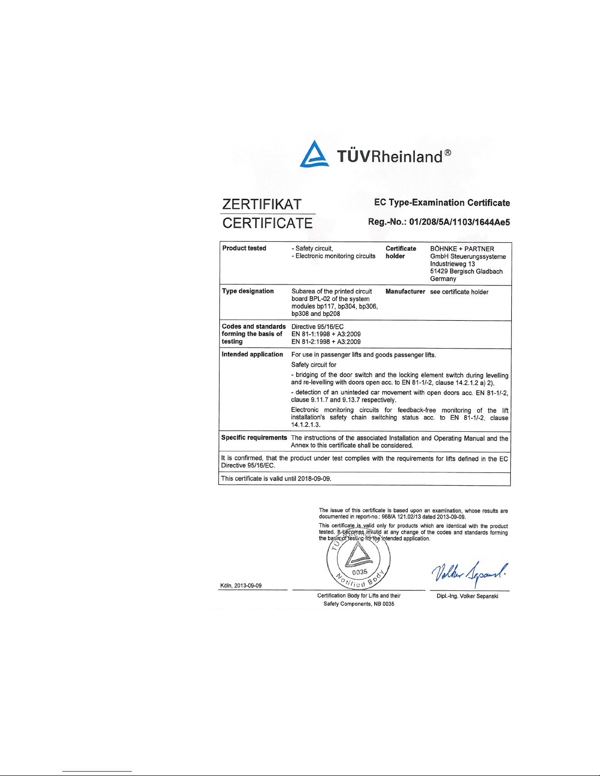
3.2 EC Type Test Certificate BPL 02 with SMZ
14 Installation Manual System »bp308« – Product Certifications
Fig. 2
System module
bp117/304/306/bp208/bp308
as subsection of BPL- 02
Circuit board
Requirements of
Directive 95/16/EC
EN 81-1:1998+A3:2009
EN 81-2:1998+A3:2009
Registration no.
01/208/5A/1103/1644Ae5
from 09th September 2013
Page 14
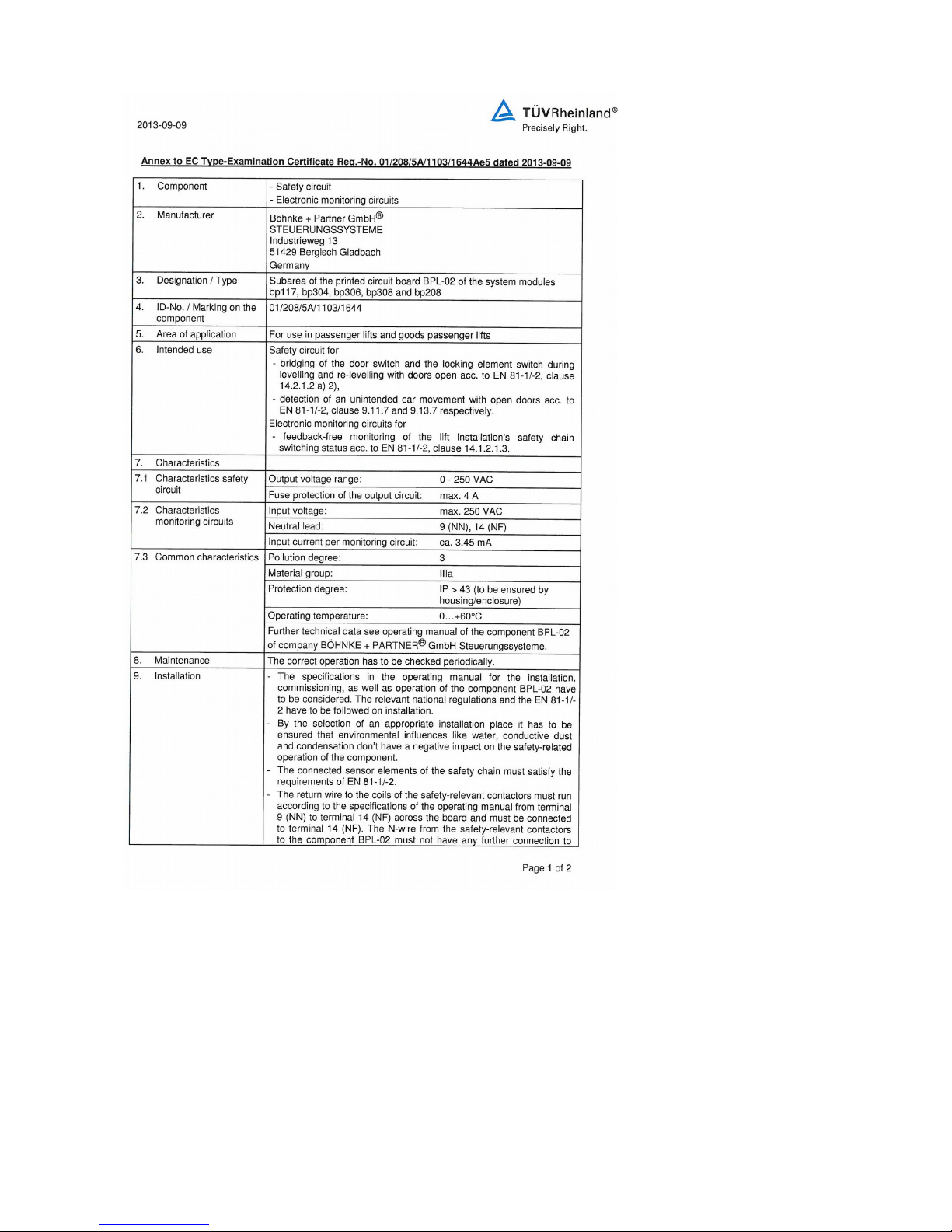
15
Page 15
16 Installation Manual System »bp308« – Product Certifications
Page 16
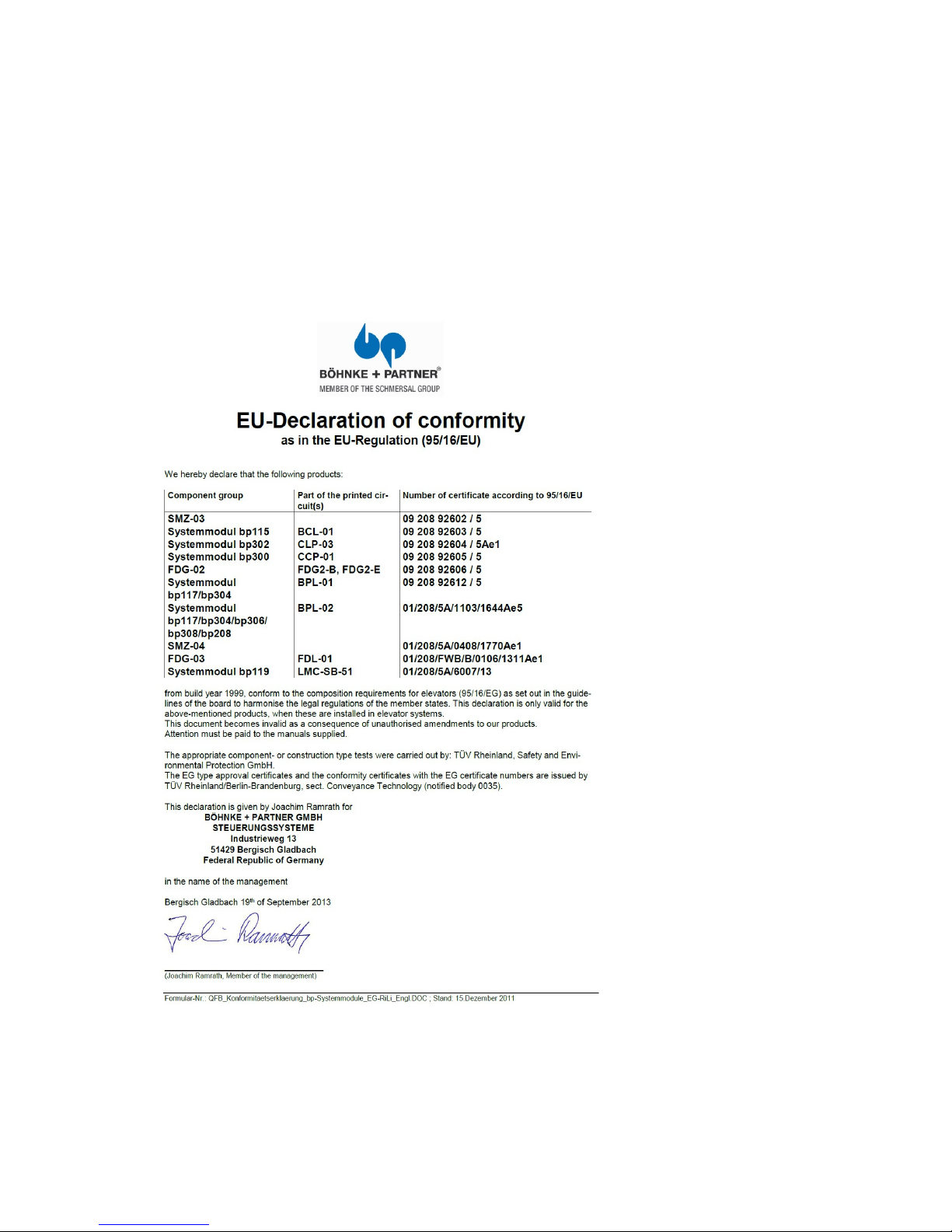
3.3 EC Certification bp308
(95/16E/G): 01/208/5A/1103/1644Ae5
Named location, ID no 0035
3.3.1 Declaration of Conformity with EC Directive
(95/16/EG)
17
Page 17
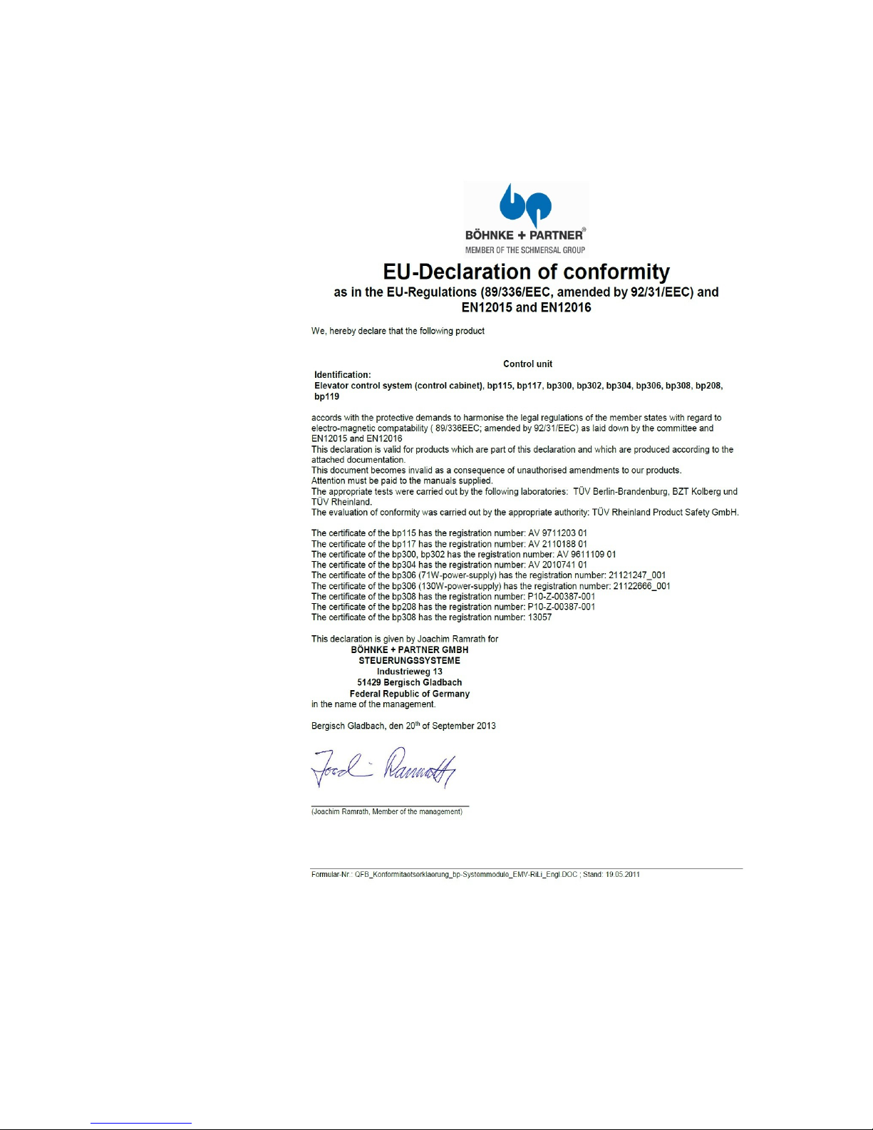
3.3.2 Declaration of Conformity with EC Directive
(2004/108/EG) / EN 12015+EN 12016
18 Installation Manual System »bp308« – Product Certifications
Page 18
4 Standards
TIPS REGARDING OTHER REGULATIONS AND RISKS
• The procedural tips and excerpts from circuit diagrams given
throughout the technical documentation are to be applied mutatis
mutandi, i.e. to be checked for every application. BÖHNKE +
PARTNER does not accept any liability for their individual suitability.
• To ascertain proper functions of the complete control system, you
must comply with the documentation of the manufacturers of thirdparty components, which are supplied to you as well (e. g. operation instructions for the frequency inverter).
• The control system bp308 must exclusively be used for processing
information in elevator control systems.
• Control units, printed circuit boards, modules or other devices that
have been damaged on their transport to you must not be used or
commissioned.
• Printed circuit boards comprise electro-statically damageable elements. Therefore, before touching any electronic component make
sure that your own body has been discharged. You can do this by
touching a conductible earthed object (e. g. bare metal parts of the
control cabinet ).
4.1 EMC-Directives
All industrial, electronically controlled devices, such as, for example,
PCs, microprocessors, computers, SPSs, can be influenced by interference pulses if they have not been protected accordingly. These
interference pulses can be caused by external appliances, such as e.
g. voltage fluctuations in the feed-line or control pulses of the power
parts in the frequency inverter. BÖHNKE + PARTNER have taken all
usual measures while manufacturing the control unit. The installed
components are only slightly sensitive to interferences from their
environment.
ATTENTION!
• Follow the EMC instructions given by the manufacturer of the frequency inverter at all times !
• Should you have any question concerning the EMC Directive
please ask our service team .
• Please also pay attention to the tips concerning interference suppressing measures given in this manual.
19
Page 19

4.2 EN 81
EN 81-2 regulations :
We providently point to the fact that BÖHNKE + PARTNER do not
accept any liability for damages that might be traced back to the
adherence to EN 81-2 regulations! Example: Re-levelling of a
hydraulically operated elevator even in case that the runtime monitoring has responded due to a phase failure.
20 Installation Manual System »bp308« – Standards
Page 20
5 Control System »bp308«
5.1 Description of the Product and its Functions
The control system bp308 is an electronic component for the control
of lifts. Different designs are available, with safety circuit interrogators for different voltages and different power units with varying outputs, with or without integrated safety/protective circuit.
Basic functions of an lift control unit, such as a stabilized power unit,
safety circuit interrogator and safety circuit have consistently been
integrated in the control system bp308.
The control system bp308 is a decentralized microprocessor system
with distributed »intelligence«. The decentralized components are
linked to the unit via its two CANopen interfaces as a standard, pursuant to the international standard. CANopen CiA-417 (www.CAN-
open-Lift.org). There are further interfaces for older protocols com-
mon in the lift industry.
The control system bp308 is composed as follows:
Stabilised, primarily clocked power unit with 2 voltages
5 V DC 2 A (internal only),
24 V DC 2.2 A (at the terminals ),
Power Fail recognition 150 VAC,
Emergency light 12 V, 600 mA, total discharge protection at 10 V,
Pre-control,
Safety circuit interrogator,
Safety/Protective circuit (optional),
Freely programmable inputs, outputs and relays,
Electronically monitored standard inputs and outputs as well as
interfaces for:
The selection of the frequency inverter with DCP3 and DCP4+
interface,
Absolute encoders of different makes and technologies,
Data remote diagnostics with WinMOS®300 per Bluetooth™, WiFi,
modem USB) or Ethernet,
Building automation per EIS protocol, LONworks standard, OPC,
Modbus or Profibus DP.
CANopen CiA-417- components,
LAN for remote diagnostics and monitoring,
USB laptop connection for diagnostic purposes and software
updates,
USB host for USB sticks, modems, Bluetooth™ or WiFi adapters,
21
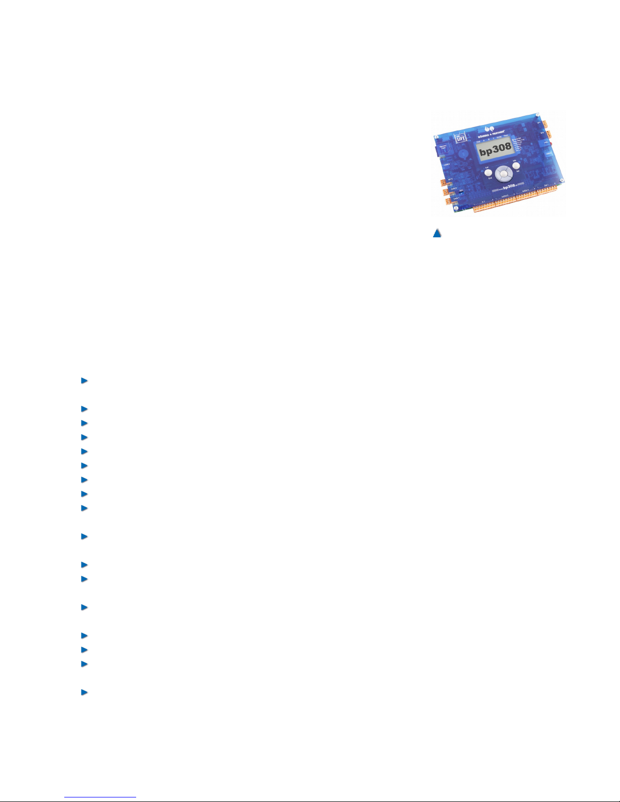
Fig. 3
The "bp308" control system features the latest lift technology
interfaces .
Page 21

Memory card slot for software updates, log files, and parameter
backups.
Based on these concentrated functions and the conception of decentralized control, small control cabinets can be used. The standard control cabinet for the control system bp308 is 600 x 600 x 250 mm and
thus intended for lifts with limited space only.
In combination with the data remote monitoring system WinMOS®300
®300 (www.WinMOS.de) it can significantly increase the availability
of the lift. In addition, this system allows you to completely match the
service intervals to the requirements
5.2 Summary of the Functions of bp308
Controls of a single lift
Controls of a bank of 8 lifts without group computer
128 landing settings
SFS – automatic push button control
SFR – automatic push button control with landing call memory
(»Taxi control«)
1KS – 1-button collective control
1KSab – 1-button down collective control
1KSauf – 1-button up collective control
2KS – 2-button up and down collective control
Operating data logs: travels, operating hours, malfunctions, mes-
sages
Rope traction lift: pole changing, one speed, two speeds, frequency
inverter, Ward Leonard drive
Hydraulically operated lift: star-delta and direct start, valve control,
soft start, frequency inverter
Positive temperature control of drive motor, integrated
Safety circuit, integrated (230 V AC standard, 48 V DC optional)
Main contactor selection 230 V AC, integrated
Safety circuit type SMZ-04, integrated
Internal primarily clocked, stabilised and short circuit resistant
mains power pack with terminal connector to the control unit
Inputs and outputs for every standard application, integrated
Inputs and outputs expandable in steps r
Positive circuitry (24 V DC)
Outputs overload protected
Diagnostics of inputs and outputs suitable for diagnostics by LCD
or laptop
Diagnostics and configuration of the CANopen components using
the CANwizard
®
Operator guidance using a laptop with WinMOS®300
22 Installation Manual System »bp308« – Control System »bp308«
Page 22

Operator guidance using 7 keys and illuminated graphic LC display
Parameter setting on site using the LCD, mobile phone, Bluetooth
or laptop
Parameters safely memorised in EEPROM (2 complete data sets)
Real-time clock integrated
Setup menu separate from service menu
Code lock can be set separately
Menus provided in German, English, Dutch, and Swedish
Integrated interfaces for DCP, LAN, USB and CANopen
Optional remote diagnostics via modem (USB) or LAN
Different codes possible for landing signals and direction indicator
(Gray, binary, user-specific)
Zero load, full load and actual load in kg
Direction indicator, landing gong, selecting landing door as well as
direction of travel
Home landing adjustable
Fire emergency landing and emergency power landing adjustable
Monitoring and waiting landing adjustable
Fire brigade landing adjustable
Parking programs adjustable by LCD
Door tables A, B and C externally switchable
Magnet switch selector with 4 and 6 switches
Absolute encoding selector with AWG-05 executed in CANopen
Next landing and short landing distance up to 15 mm (with absolute
encoding only)
Selective landing calls for door sides A, B and C
Priority landing calls with two stages (low and high position )
Door selection for sides A, B and C (all door operators)
Doors adjustable to different times and functions
Zone module (SMZ04) for doors starting to open during landing
approach and for re-levelling)
Door locks on side A, B or C separately selectable by lockage con-
trol
Service intervals settable in relation to travels, hours and date
Malfunction stack memory of up to 128 messages (type of malfunc-
tion, landing and time (date and hour) as well as signal map)
Malfunction list (type, landing and frequency)
Batch memory of up to 128 important messages
Monitoring possible with laptop on site
Remote fault diagnostics possible with WinMOS®300 via modem or
LAN
2 relays, freely programmable with one normally closed contact
2 relays, freely programmable with one normally open contact
4 relays, freely programmable with one double throw contact for,
e.g., door A and door B for electronic door control units
23
Page 23

Company logo (text) programmable on LCD
Landing names (text) programmable
Optional guest operation, chemical operation, docking service,
earthquake operation and other special function can be purchased.
RoHS compliant production (lead free)
24 Installation Manual System »bp308« – Control System »bp308«
Page 24
5.3 Decentralised Lift Control
The bp308 is a decentralized control system, i.e. the »intelligence« is
distributed on the linked devices and does no longer exclusively take
place in a centre unit. This decentralized lift control is based on the
CANopen application profile CiA-417 (www.CANopen-Lift.org). It is
via this globally standardized application profile that the different
components of the lift bank communicate. The linked components
have a complete functional scheme each and are thus in a position to
make many decisions themselves. This profile enables open modular
systems that can assume very complex control tasks.
5.4 The Group System
The up-to-date group control system is equipped with a powerful 32bit processor able to evaluate a large variety of information from the
entire lift group within the shortest time and on this basis make the
decisions for the group operation.
The group control system guarantees the smooth operation of a
group of two to eight lifts, based on the CANopen-based application
profile CiA-417. All data and commands for all components are
provided on the bus in compliance with the standards. Each group
computer is thus able to decide on its own in which sequence and by
which group member the individual calls should be ideally processed.
The group function does not require a master computer but one may
be used optionally to expand group performance by certain special
functions such as the load-related evacuation of all lifts within one
building when using emergency power or in the case of fire or the
automatic static evaluations for determining group parameters .
Landing calls are entered via bus nodes that may be located in the
landing call unit or in the control cabinet. These nodes evaluate the
signal received and make it available to all group members at once
on the CAN Bus − as a message that states direction, priority, destination etc.).
Landing calls are entered via bus nodes that may be located in the
landing call unit or in the control cabinet. These nodes evaluate the
signal received and make it available to all group members at once
on the CAN Bus − as a message that states direction, priority, destination etc.
If an lift no longer participates in group operation because it has been
switched to inspection mode during maintenance work, for instance,
the other group members receive this information immediately so that
it can be taken into account in the calculations. If several lifts are able
to answer a call at the same time, the lift that has been standing still
25
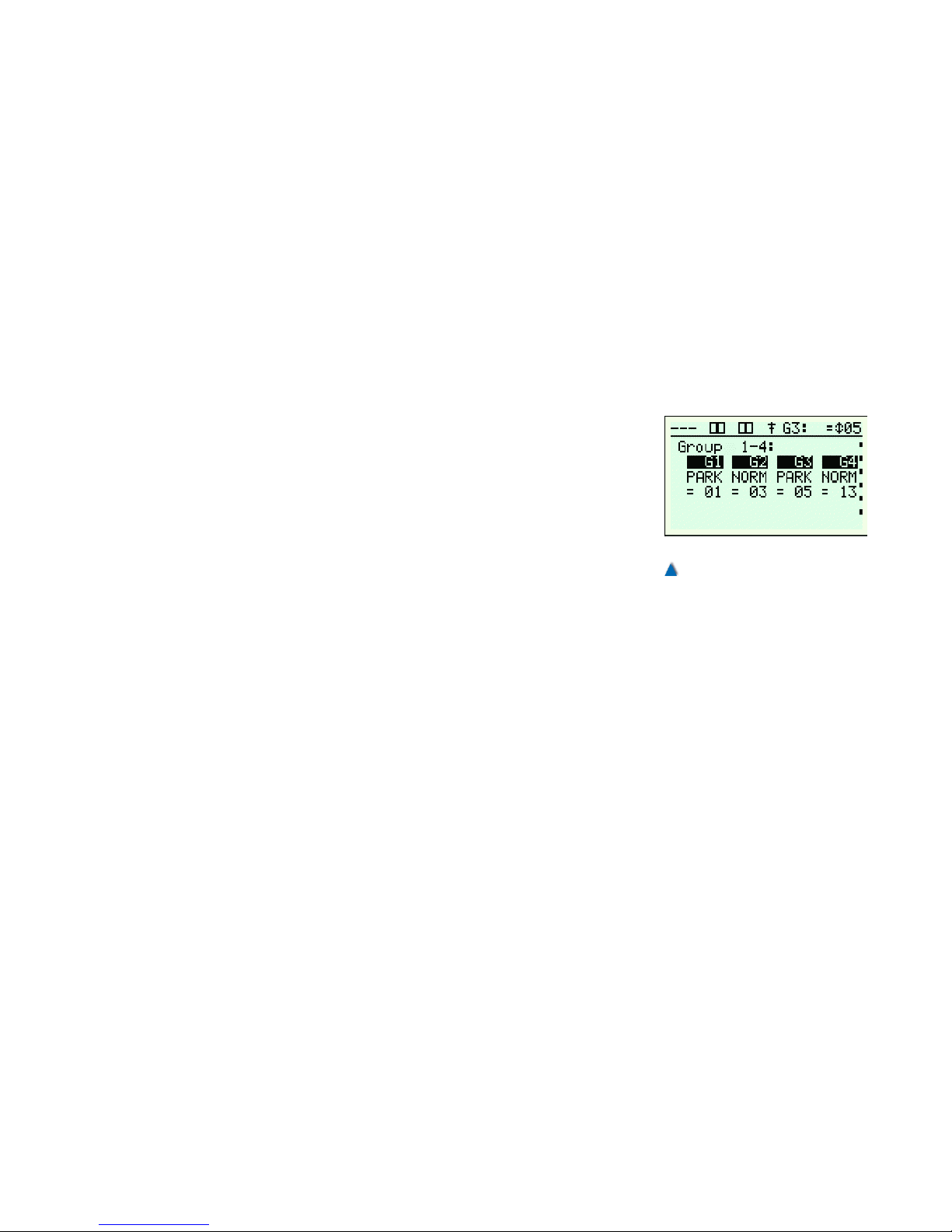
Fig. 4
Group status in bp308
Page 25
the longest picks up the call. If the standing times are also the same,
the rule G1 before G2 applies.
The following states are taken into consideration for aspects such as
the group algorithm:
• Distance to target landing
• Opposite travel/call direction
• Llift is stopped or running
• Number of interim stops on route
• Lift cabin call on the target landing
• And others.
5.4.1 Priority Calls
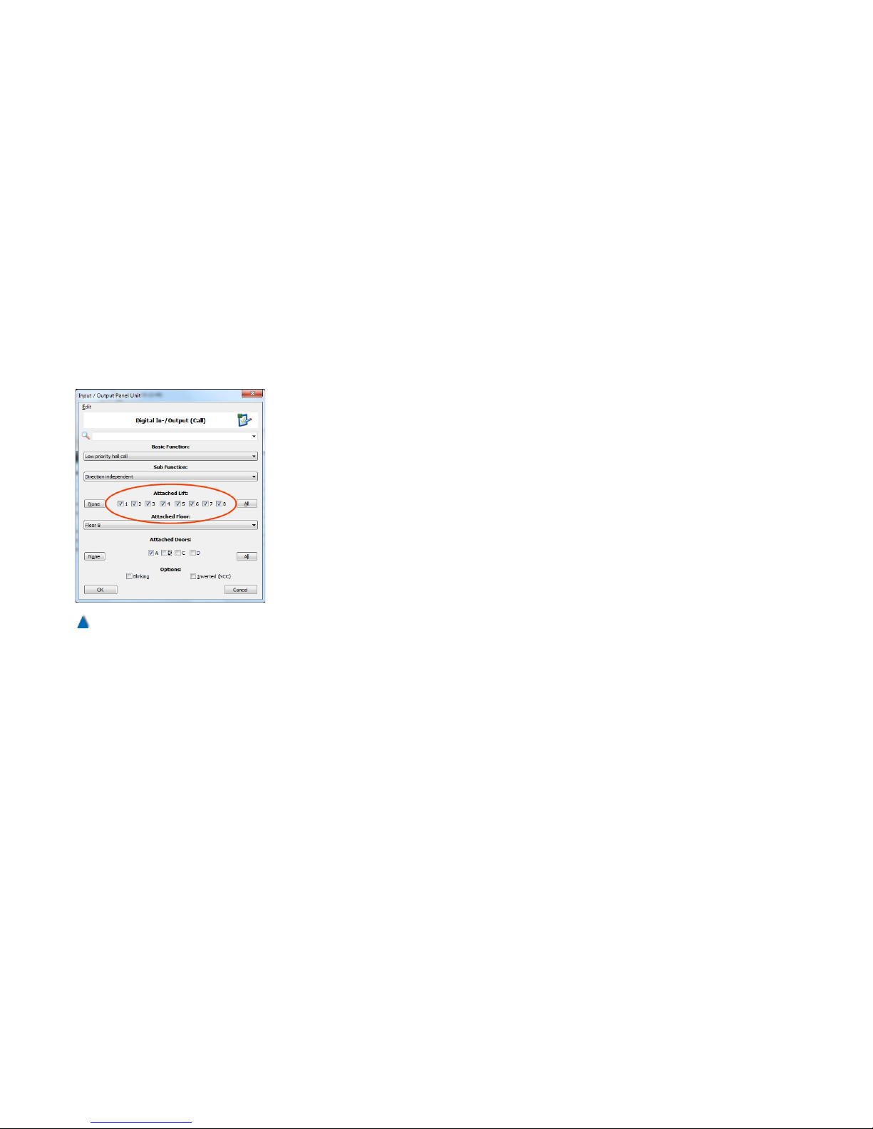
When setting priority calls on the BPC itself or a CANopen component such as CAP-01/02 or CIO-01, it is stated which lifts should
answer the priority call. The most effective of the selected lifts (see
illustration) then answers this call. Two further options, "collect priority calls" and "several priority calls per landing" in the group setting of
the service menu make it possible to call further lifts if one is already
answering the priority call on the landing on which the standby delay
is running. This option is intended for bed transports, for instance. A
high priority landing call cancels a low priority landing call. Otherwise,
the same rules apply for the high priority landing call than for the low
priority landing call.
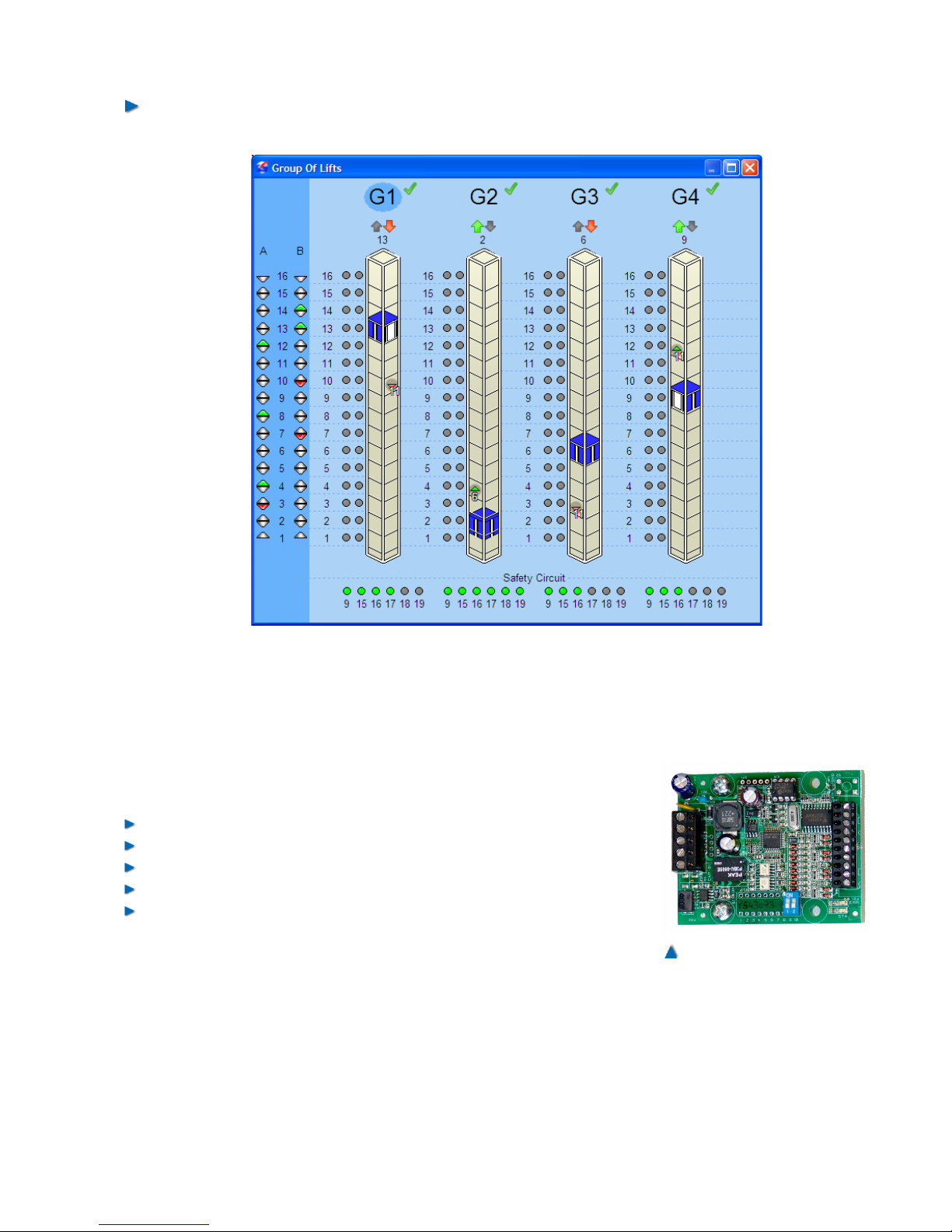
5.4.2 Group Display in WinMOS®300
WinMOS®300 provides an optional group data view in both "Diagnostics" and "Monitoring" mode. In the case of the bp308, the target
floor of the current lift call is displayed on the group panel of the lift
well. The call’s ETA (estimated time of arrival) is also dynamically displayed on the panel. This can change at any moment − e.g. when the
call situation changes. Priority landings are displayed with a special
symbol that also shows if the call has a high or low priority.
This function makes it easier to trace the processes within one group
controller.
26 Installation Manual System »bp308« – Control System »bp308«
Fig. 5
Setting the priority landings
Page 26
5.5 Components of the bp308
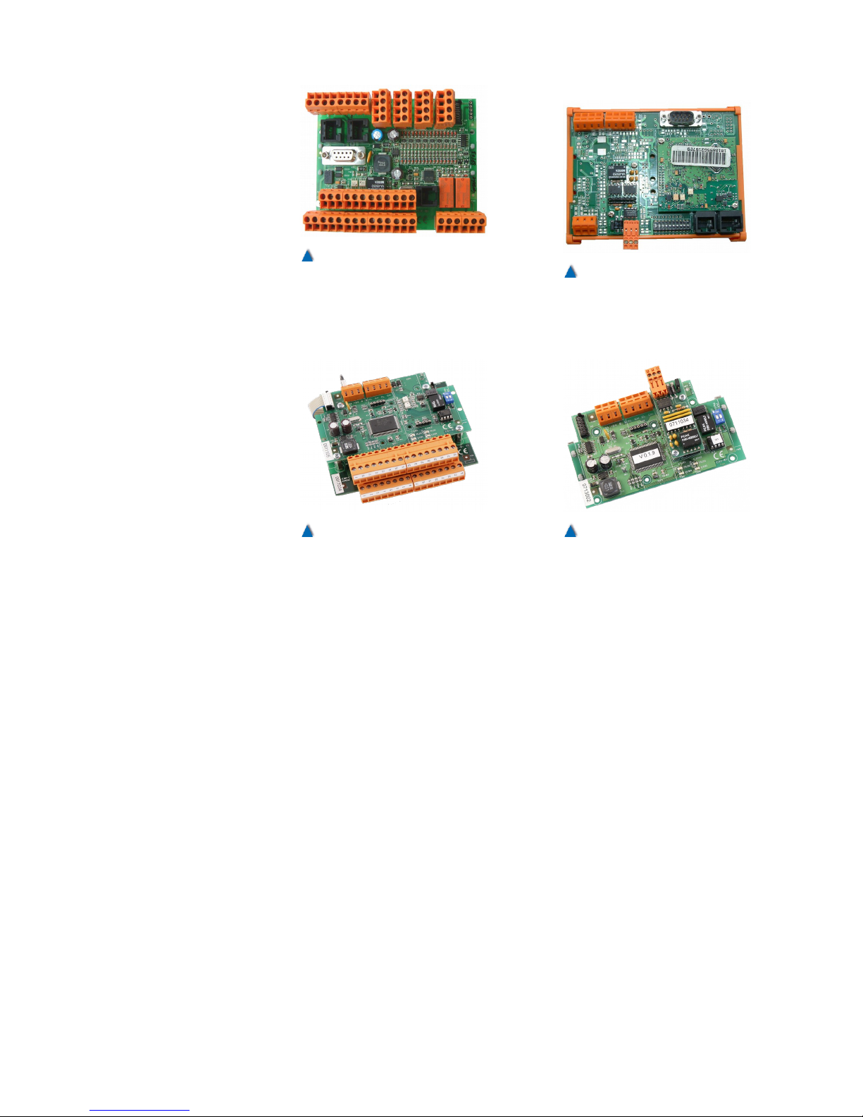
BÖHNKE + Partner can supply the following components for the control system bp308:
Landing call unit CAP-01/02
Landing call unit CIO-01
Car operation unit CLK-03
CAN data communication gateway CDG-01
CAN-Serial-Interface CSI-01
Further components from different manufacturers, such as, for
example, absolute encoders or push button units complying with the
standard CiA-417 are available and may be used .
A list of CANopen components available and their descriptions can
be accessed at www.CANopen-Lift.org.
27
Fig. 7
Printed circuit board CAP-01/02
connecting landing calls to the
CANopen bus .
Fig. 6
Illustration of the dynamic call allocation of a group controller in WinMOS®300 for the controller system
bp308
Page 27
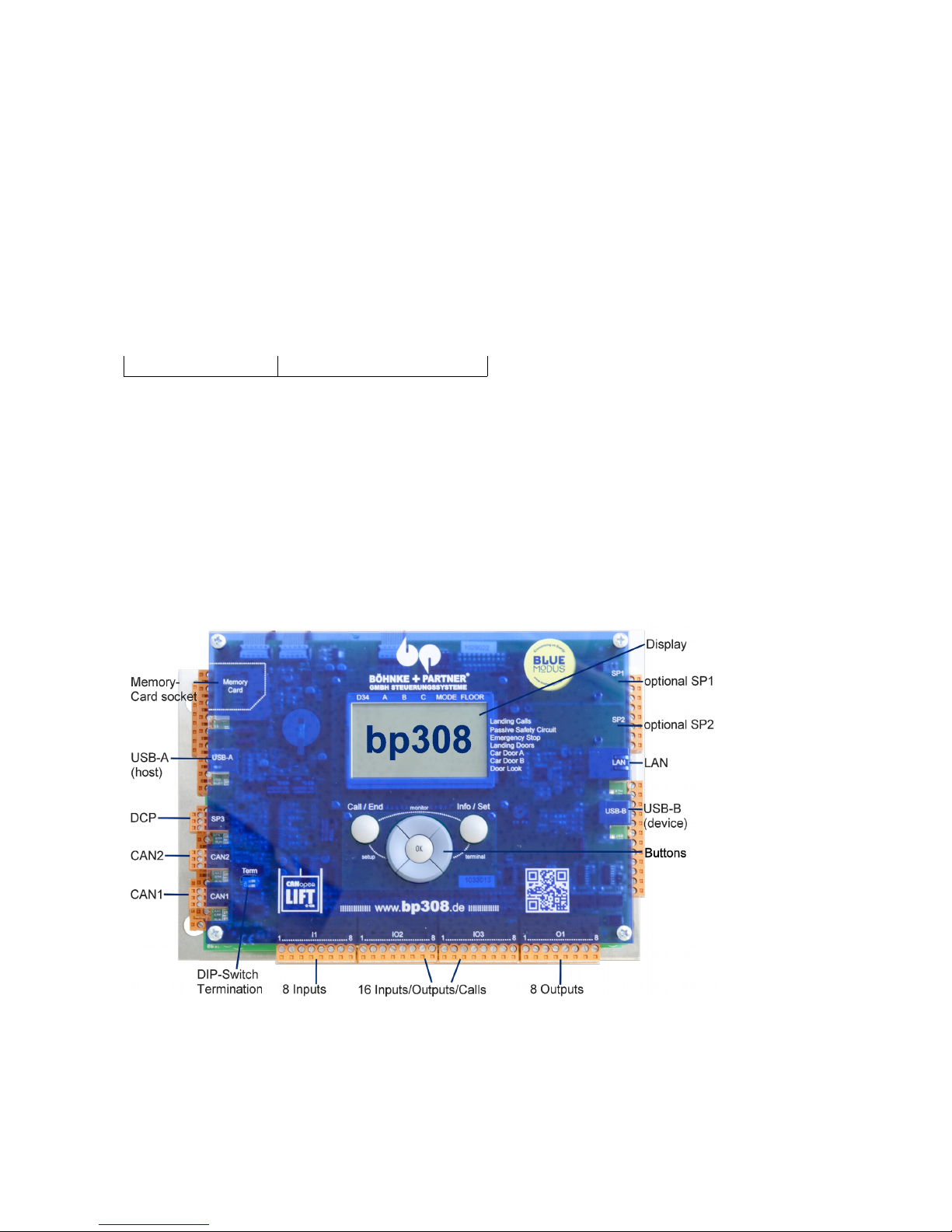
28 Installation Manual System »bp308« – Control System »bp308«
Fig. 8
Printed circuit board CLK-03
connecting the car electronics
to the CANopen bus.
Fig. 10
Printed circuit board CIO-01
connecting 32 inputs/outputs or
calls.
Fig. 11
Printed circuit board CSI-01 for
use as a gateway or repeater.
Fig. 9
Printed circuit board CDG-01
serving as a gateway between
CANopen networks or for data
remote diagnostics .
Page 28
5.6 Variants of bp308
This installation manual refers to all variants of the control system
bp308, as mentioned in the following list stating the abbreviations and
their meaning:
SMZ = Safety circuit (safety module zone)
24 V = Option 24 V safety circuit query
48 V = Option 48 V safety circuit query
110 V = Option 110 V safety circuit query
5.7 Brief Description bp308
5.7.1 Top Shot
29
382-308-010-aaa
382-308-010-aab
382-308-010-aac
382-308-010-aad
382-308-010-aaf
382-308-010-aah
Order Number Version
bp308 Standard
bp308 with 48 V
bp308 with SMZ
bp308 with 48 V and SMZ
bp308 with 110 V and SMZ
bp308 with 24 V and SMZ
Page 29
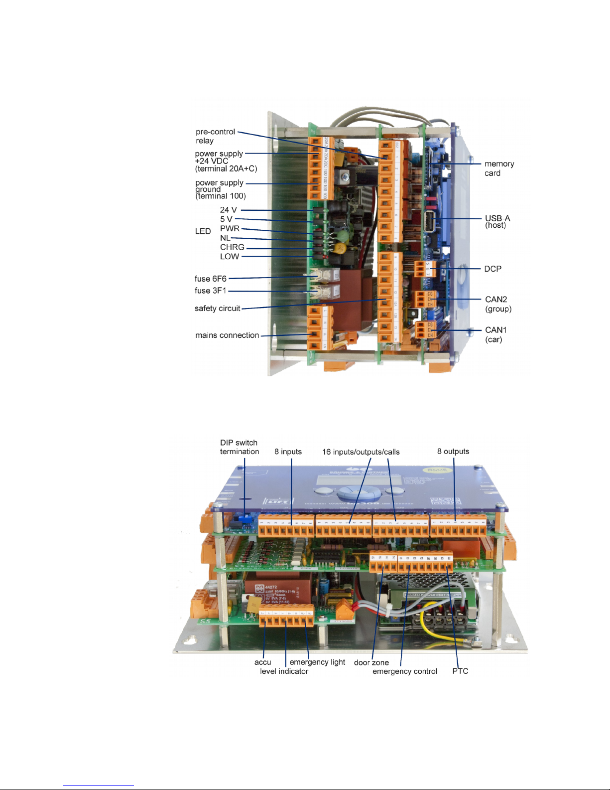
5.7.2 Left Side View
5.7.3 Bottom Shot
30 Installation Manual System »bp308« – Control System »bp308«
Page 30
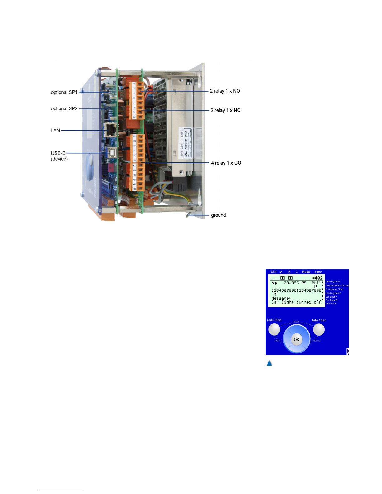
5.7.4 Right Side View
5.7.5 Operator Panel and LCD of the bp308
The operational status of the lift can be determined and parameters
set in the control unit and the attached CANopen devices with the
help of the graphic LC display and operator panel .
5.7.5.1 Standard View
Once the system has been switched on and is operating normally,
the standard view appears on the display if no special menu has
been called up. This view provides a quick overview of the current lift
status as well as individually configurable information .
The LCD displays this information as a standard:
• Lift status bar
• Safety circuit status bar
• B+P« logo (or customer-specific logo )
• Board and cabinet temperature (optional),
• Status of internal buffer battery
• Current system time
• Depending on configuration:
• Current malfunctions and messages
• Last malfunction
31
Fig. 12
Display and buttons of the
bp308. Illustration shows two
doors A and B .
Page 31
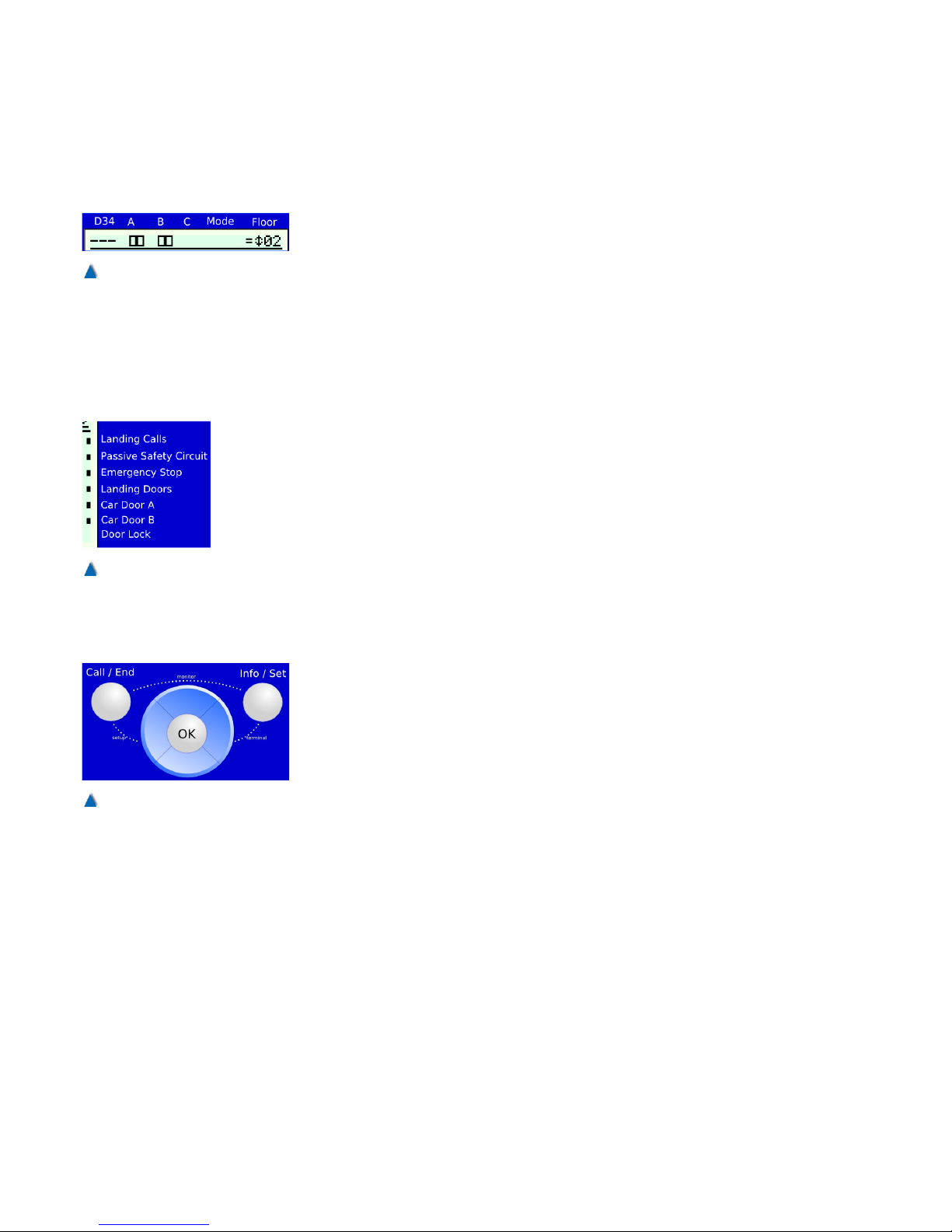
• Statistical information
• Current lift speed
5.7.5.2 Lift Status Bar
The lift status bar is shown in the top half of the display in all menus.
It provides the following information:
• Pre-control (Relay K1-K4)
• Doors A/B/C with limit switches and reversal signals (photo-
cell, door open« push button)
• Mode (e.g. status safety circuit status)
• Position information (flush-level control ) +/ =/ -
• Signalisation of travels
• Car position
5.7.5.3 Safety Circuit Status Bar
The safety circuit status bar is on the right side of the display in all
menus. It provides the following information:
• Landing control status (on/off)
• Safety circuit status (terminals
X 5.9/.16/.17/.18/.19)
5.7.5.4 Operator Panel
The operator panel is at the bottom of the display. It has 7 buttons
that are used for navigating through the various menus, displaying
status information and changing parameters.
The operator panel buttons »Up«, »Down«, »Left«, »Right« and
»OK« are arranged as a central navigation block. The »Call/End«
button is on its left and the »Info/Set« button on its right.
5.7.6 Service Menu
Parameters and times that are not safety-relevant and may be
changed during system operation such as door times, BlueModus
energy saving functions on/off etc. can be set in the bp308 service
menu.
32 Installation Manual System »bp308« – Control System »bp308«
Fig. 13
The lift status bar is displayed in
all menus.
Fig. 14
The safety circuit status bar is
displayed in all menus.
Fig. 15
Use the buttons on the operator
panel to navigate through the
menus.
Page 32
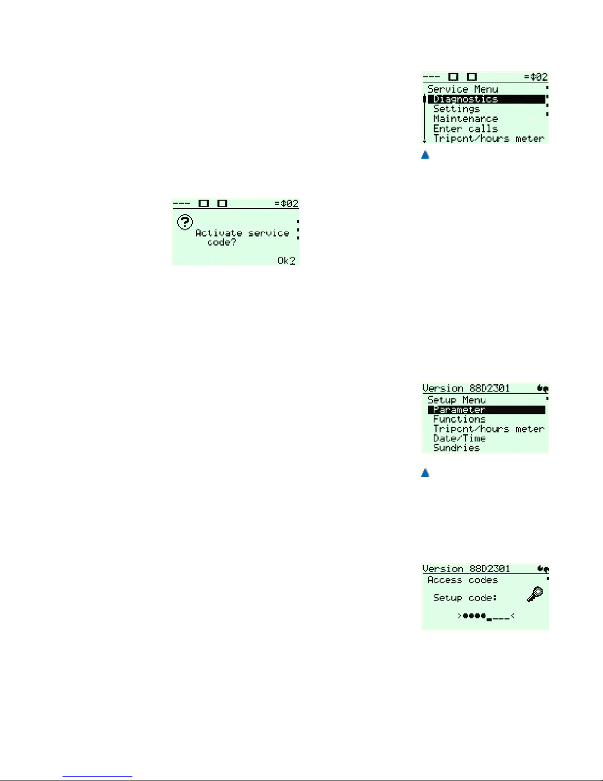
5.7.6.1 Starting the Service Menu
The display automatically switches to the service menu when pressing the »Ok« button. If a service code (secret number) has been set,
the correct code has to be entered. BÖHNKE + PARTNER do not
preset any service codes by default.
After that you can call up all service menu sub-menus and parameters and change them during the normal operations. If the control unit
is to be re-encoded after leaving the service menu, please press the
button »left« repeatedly until this question appears on the LC display:
Confirm by pressing »Ok«. A short notice appears:
Service code activated
Then you are back in the bp308 start menu .
The service code can be changed or reset at any time in the service
menu under SUNDRIES > ACCESS CODES > SERVICE CODE .
5.7.7 Setup Menu
The setup menu comprises basic parameters that cannot be changed
during normal operations, e.g. traction or hydraulic lift, number of
stops, etc .
5.7.7.1 Starting the Setup menu
To get into the basic menu, proceed as follows:
• Ensure that no persons are inside or on the car and that the
system can be switched off without any risk.
• Push down and hold the left »Call/End« button and quickly
push the »left« button.
A short notice appears:
> Entering the setup menu... <
You are now in the setup menu and all control functions are switched
off! If a service code (secret number) has been set, the correct code
has to be entered. BÖHNKE + PARTNER has preset it to >5061<.
Once the correct code has been entered you can call up all menus
and parameters and change them. To leave the setup menu quickly
press the left »Call/End« button again.
33
Fig. 17
The bp308 setup menu
Fig. 16
The bp308 service menu
Page 33
5.7.8 Call Menu
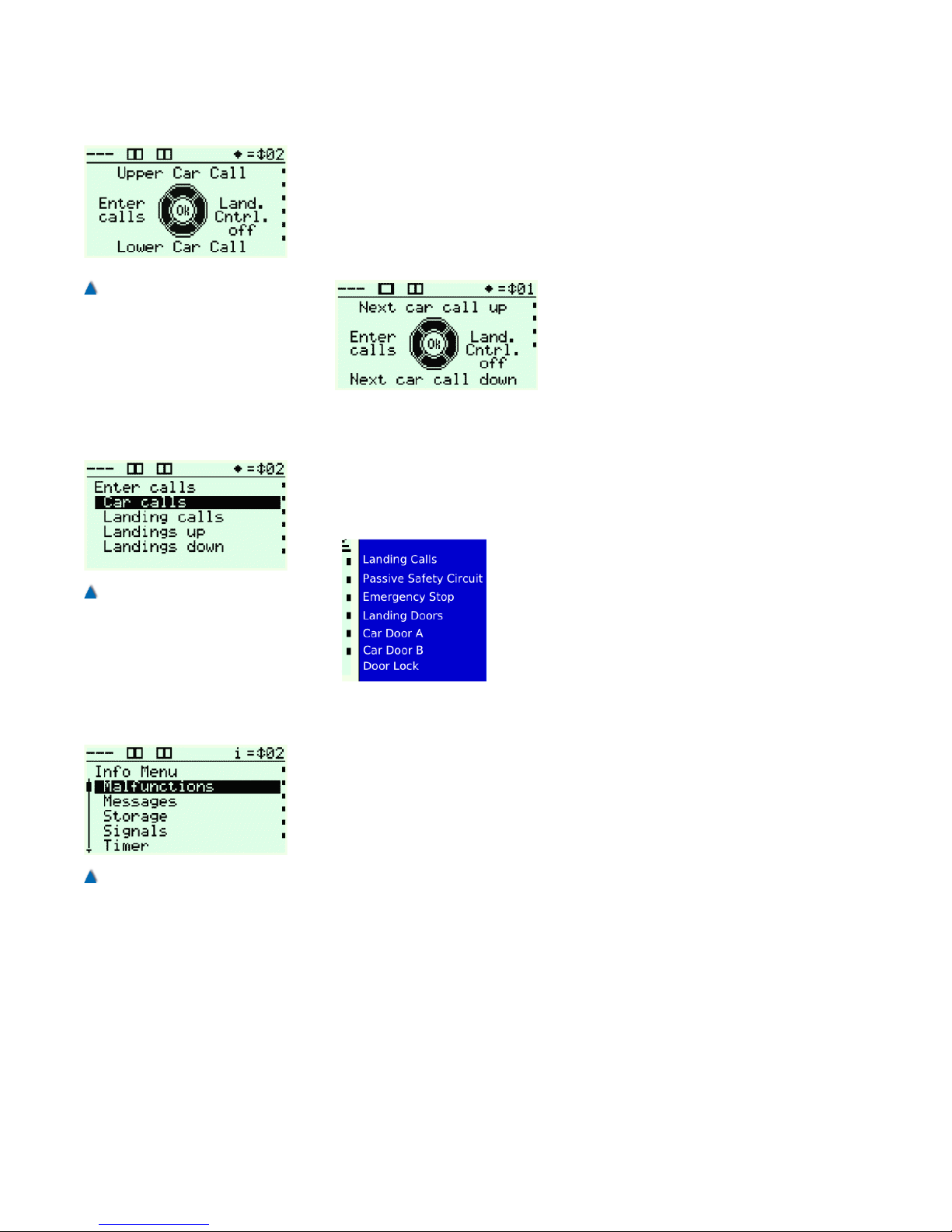
From the service menu you can access the call menu directly by
pressing the »Call« button. The active menu is indicated by a diamond symbol in the lift status bar.
In the call menu, you can make a cabin call to the top or lowest stop
with one click.
By clicking the OK button, the targets
switch from cabin call top/bottom to
next cabin call top/bottom. Now you
can make a cabin call to the next stop
of the current car position in an
upward or downward direction. You
can also select between door open or
close with another click in the call menu (optional).
If you want to send cabin or landing calls to specific landing, you can
call up the Make calls dialogue by clicking on the »Left« button where
you can select the required call type and make calls to the respective
landings and doors.
When in the call menu, you can activate or
deactivate the landing control by clicking the
»Right« button. The current landing control
status is always displayed in the safety circuit
status bar as a dot before the text Landing
Calls. If a dot is showing, the landing control
is active and you can make landing calls .
5.7.9 Info Menu
In the info menu you can switch between two menu points with the
click of one button. You can use this option to change service menu
parameters or make calls and view the system reactions such as
travel signals with just one click.
Click the Info/Set button once to access the info menu. When the
menu is active, an "i" is displayed in the lift status bar and you can
navigate through the menu. Another click takes you back to the menu
point at which you activated the info menu. You can now switch
between the two menus with the click of one button.
34 Installation Manual System »bp308« – Control System »bp308«
Fig. 18
The symbol for the bp308 call
menu is a diamond in the lift
status bar .
Fig. 19
The lift can be sent to specific
landing with the 'Call' dialogue.
Fig. 20
You can quickly switch between
two sub-menus in the info
menu.
Page 34
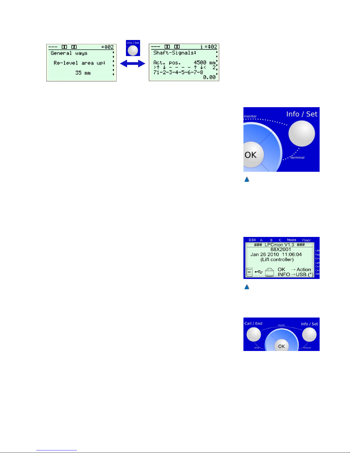
5.7.10 Terminal-Mode
A method for components attached to the CAN bus sending the contents of their displays to the bus and for other devices to display this
content and to navigate through it using the menu of a third-party
device has been specified in the CANopen CiA-417 Lift control
application profile.
This method has been integrated in the control system bp308 and is
available in terminal mode.
You can switch to terminal mode by pressing the Info/Set and
»Right« button at the same time. The bp308display now shows the
menu of an attached third-party device. The navigation buttons »Up«,
»Down«, »Left«, »Right, »OK«, and »INFO« are now sent to the
remote device.
Terminal mode is ended by clicking the »CALL« button and the last
bp308 menu point is displayed again.
5.7.11 Monitor Program LPCmon
You can use the 'LPCmon' monitoring program to query the lift software program version and update the system software. This process
should only be carried out by instructed personnel upon request by
BÖHNKE + PARTNER GmbH.
5.7.11.1 Starting the Monitoring Program
To access the bp308 monitoring program, first ensure that no persons are inside the car and that deactivating the system cannot create any dangerous situations.
Hold the »Call/End« and »Info/Set« buttons at the same time for
approximately 2 seconds. This starts the monitor and all control functions are now switched off!
35
Fig. 21
Terminal mode is accessed by
pressing the Info/Set and Right
buttons at the same time.
Fig. 22
LPCmon' monitoring program
Page 35
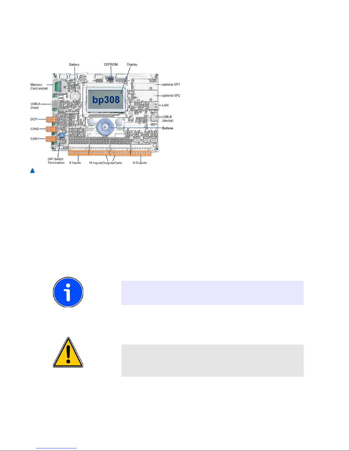
5.7.12 Program and Parameter Memory
5.7.12.1 General Information
The illustration shows the positions of the
memory card slots, interfaces, EEPROMs
and internal flash memory.
The printed circuit board houses the digital
control electronics and the processor, the
flash program memory, EEPROM parameter
memory, realtime clock, battery, LC display
and buttons.
The interfaces for 2 CAN networks, serial
data remote transmission (optional), USB or
Ethernet, USB host and USB device, and the
serial selection of a frequency inverter via
DCP are also mounted on this board. In
addition, the bp308 has 8 inputs and 16
calls, which can also parameterised as
inputs or outputs. The lift program is stored
in the flash memory. All lift-specific parameters such as type, stops,
doors, times, parking landings, etc. are safely stored in EEPROM.
5.7.12.2 Exchange
To exchange the EEPROM use a special EEPROM snag and draw
the EEPROM from the socket at right angle. Insert the new EEPROM
at right angle and press it into the socket while applying slight pressure. You must ensure that the marking (groove) is in the correct
position to insert the component the correct way round!
INFO!
As the pins of EEPROMs are at risk of bending or breaking off, it is
strongly recommended to use a snag as an appropriate tool .
ATTENTION!
The guarantee expires if program changes and subsequent changes
of the lift controls are carried out without assistance of the BÖHNKE
+ PARTNER service team .
36 Installation Manual System »bp308« – Control System »bp308«
Fig. 23
Printed circuit board BPC-04 and the arrangement of its key
components and interfaces.
Page 36

5.7.12.3 Software Update
A software update is necessary if the lift system is to be refurbished
with additional functions. Exchanging the EEPROM is necessary only
if the printed circuit board needs to be exchanged and the data
related to the lift has to be transferred to the new printed circuit board
.
INFO!
Before each software update you should back up the existing software version and parameters on a memory card, mobile phone or
laptop. Then you can update the system with the new software after
which you should check the system. The EEPROM parameters and
existing lift program backup can be carried out on the LPCmon monitor.
There are several ways of updating software: with a file stored on a
memory card or USB stick and via the USB-B (device) connection
(laptop). To carry out an update using a memory card or USB stick,
place the memory card containing the new software version in the
memory card slot or the USB stick in the USB-A connection of the
bp308. Switch on the controller and hold down the »Call/End« and
»Info/Set« for approximately 2 seconds to start the LPCmon monitoring program. After clicking OK, you can access the storage medium
(memory card or USB stick) containing the new program version via
the Open file menu point. Navigate to the file (e.g. 88D2207B.bin) on
the medium containing the new program and select it. You can now
update the software. Follow the instructions on the display
INFO!
A software update deletes the previous software version! Please
obtain information about the full functionalities of the new version and
back it up, if necessary, before commencing with the update .
The system needs to be rebooted after a successful update by pressing the »Call« button. The system start and subsequent system
check should be error-free
You can view the current program version number on the display in
the service menu under system info.
The program version is labelled according to the following key:
e.g. label: 88D-2101
• 88 = For target hardware:
• 88 and 78 / bp308
• 50 and 40 / bp119
• D = Main version label:
• D / standard main version (no longer modified)
37
Page 37
• S / special version (customer version different from
standard version
• X/ current intermediate version (will become D version)
• 21 = Key of the year the program was created:
• 21 / 2011
• 22 / 2012 ...
• 01 = Current version
You can also use the »Fw308« to update the software via the USB-B
interface. Please contact the service department of BÖHNKE +
PARTNER to get assistance in the use of this program.
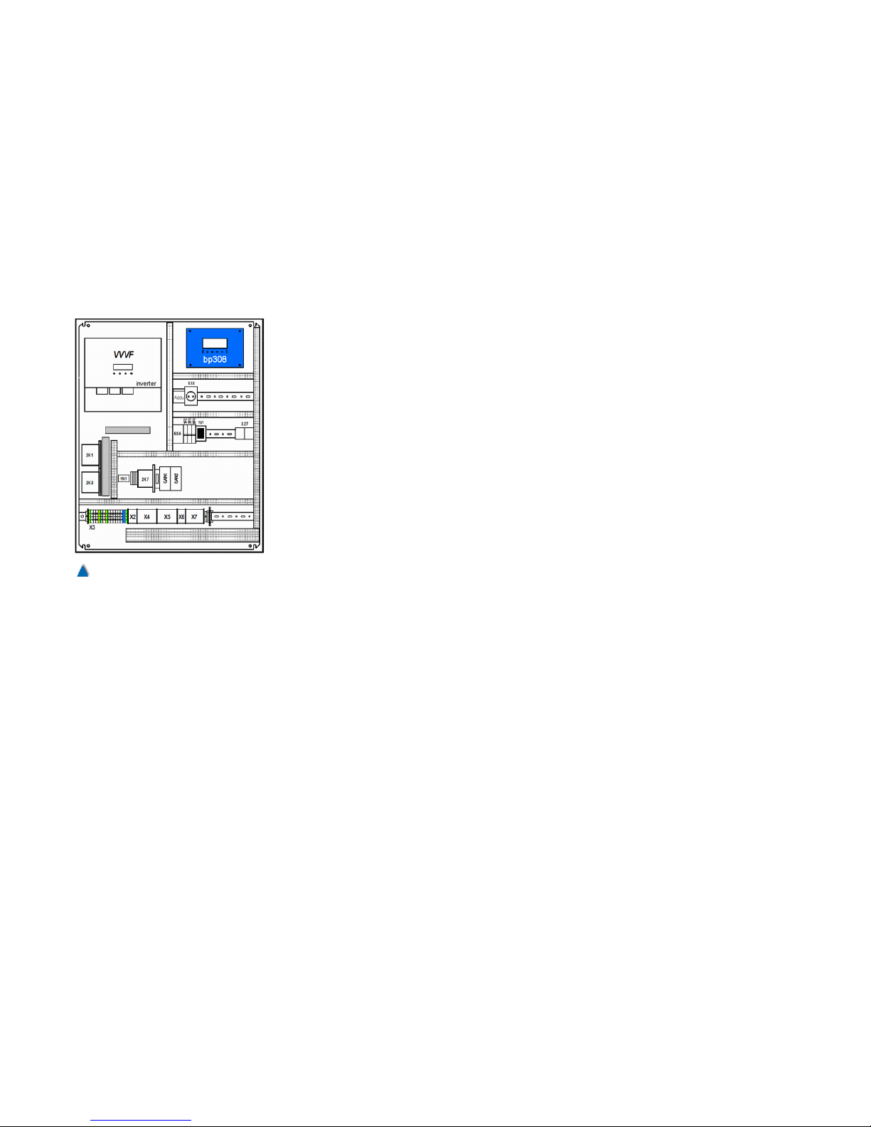
5.7.13 Control System bp308 and Frequency
Inverter together in one Cabinet
The control cabinet is made of painted sheet steel. The wall-mounted
cabinets have holes on the back to fix them or thread bolts to which
the mounting plates included in the delivery can be attached .
Standing cabinets are mounted on the supplied feet or a pre-made
frame.
They are placed an upright position so that the ventilation slots are
clear. Please ensure that sufficient sound proofing is installed
between the cabinet and the building in critical environments. In such
cases, all contactors and the entire mounting plate inside the cabinet
can be delivered with sound proofing already installed .
A sound pressure level of approximately 55 db (A) was measured at
our standard control cabinets with closed doors and the control system bp308 at a distance of around 1 m and 1.6 m height. This corresponds to a sound level somewhere between a turned-down radio [40
db(A)] and a normal conversation [60 db(A )].
The cables enter at the bottom of the cabinet. Please use the correct cable connections.
The cable duct (optional) for the ingoing lines and cables can be
removed if necessary for easy insertion.
Control cabinet:
• Enclosed (DIN 41488)
• Structured paint RAL 7032 (grey)
• Installation plate with cable duct
• Mains contactors insulated by rubber-bonded metal buffers
• Protection class IP 54
• Filter protection, if required
• Door lock: triangular grater or special lock
• Wall-mounted
• Bottom cable inlet
38 Installation Manual System »bp308« – Control System »bp308«
Fig. 24
Standard control cabinet containing bp308 as well as frequency inverter
Page 38
• Dimensions:
800 x 800 x 300 mm standard
800 x 1000 x 300 mm (thyristor-control)
1000 x 1200 x 300 mm FRQ (integrated frequency inverter)
• Mounted on rubber-bonded metal buffers (optional)
5.7.14 Easy Service - thanks to clear Layout
Assembly
The cables are installed on the base plate according to industrial
standard. Incoming lines can be laid in the cable duct. All processor
terminals are connected to a separate terminal strip arranged at the
bottom of the control cabinet. The control components are arranged
on a zinc-plated installation plate. The dimensions stated refer to a
standard configuration of lift systems with eight or more landing call
stations and with a main drive power of max. 15 kW. Systems with a
higher power can be supplied on demand .
5.7.15 Control Cabinet with bp308 unit
Control cabinet:
Structured paint RAL 7032 (grey)
Installation plate with cable duct
Protection class IP 54, with optional air filters
Main contactors on rubber-bonded-to-metal buffers (optional)
Dimensions: 800 x 800 x 210 mm
Door lock: triangular grater
Wall-mounted
Bottom cable inlet
Main Voltage
3 x 230 bis 500 V AC 50 Hz N PE
Safety circuit
230 V AC
Main Power supply (integrated)
Output 50 VA
Control voltage 24 V DC / 2,2 A
Electronics voltage 5 V DC
Rectifier
Brake (rope traction) 180 V DC / 4 A
Lock (optional) 180 V DC / 4 A
39
Page 39
Valves (hydraulics) 180 V DC / 4 A
Contactors
Nominal current 14 A
Output 7,5 kW AC 3-operation
Make Telemecanique (other brands
optional)
Terminals
Brand Weidmüller or WAGO
Positive temperature control
integrated in bp308
PTC threshold values normal operation < 2.2 kΩ ;
thermistor tripping > 2.7 kΩ
Battery-powered auxiliary power supply unit (emergency light ) BPN02A
12 V DC, including monitoring of cabin illumination voltage
Control system
System module bp308, 32-Bit multiprocessor system
Earth leakage circuit breaker (integrated)
For re-levelling, doors starting to open during slowdown, and
uncontrolled car movements with open doors (like SMZ-04)
Well teaching system
Magnet switches,
Absolute encoder
Other transmitter systems on request
Inspection control unit
Casing made of metal or impact-proof plastic with sufficient ter-
minals
Control elements integrated in the teach pad
Documentation
Circuit diagram (DIN A4 can be copied)
Legend of the operation elements on the circuit diagrams
Parts list for control unit and port assignment
Description of CPU and program summary
Description of general operation
Documentation for acceptance tests (TÜV) of bp308, including
current terminal assignment list
40 Installation Manual System »bp308« – Control System »bp308«
Page 40

Description of the safety circuit
Standards and safety regulations
EN 81, SIA, ÖNORM, DIN, VDE, VBG 4
5.7.16 Standard Features
Assembly
The system bp308 is supplied ready for installation, mounted on a
stable aluminium plate. The electronic unit consists of the stabilized
power supply, the power circuit board and the computer board, safely
joint and wired. All signals are fed out via plug terminals or standardized standard plug connectors .
Dimensions
B x H x T 270 x 170 x 180 mm
Power Supply (Integrated)
Control voltage: 24 V DC / 2,2 A
Electronics: 5 V DC / 2,0 A
Overload protector, power fail
Pre-control
Interface relays selecting the mains contactors
Safety Circuit Monitoring
230 V AC electronic, TÜV-inspected (German Association for Technical Inspection ),
Positive Temperature Control
Monitoring all common PTC thermistors
System Control
Main processor 32-Bit microprocessor (ARM)
LC-Display (integrated)
Graphic, 128x64 pixel, illuminated
Maintenance, diagnostics, and parameterisation tool
Travel and Operating Hours Counter
Integrated as standard (including pre-warning threshold for rope
replacement)
Operation
41
Page 41

7 command and programming buttons (Call / End, Info / Set, Up,
Down, Right, Left, OK)
Functions, intervals and lift processes can be freely adjusted
Controls can be locked with codes.
14 Inputs
24 V DC, opto-decoupled, input current approx. 10 mA
8 Outputs
24 V DC, 24 V DC, opto-decoupled, short circuit resistant, overload
resistant
Output current 280 mA, power 6 W
16 Calls
24 V DC,DC, opto-decoupled, input current approx. 10 mA, output
current 280 mA, power 6 W, short circuit resistant, overload resistant
Calls may also be freely parametrised as additional inputs or outputs.
Relay Outputs (Programmable )
Two relays, contact 230 V AC / normally closed contact
Two relays, contact 230 V AC / normally open contact
Four relays, contact 230 V AC / make-break contact
Doors
Integrated selection of three electronic door drive units
Safety Circuit
For relevelling and doors starting to open during slow down (e.g.
SMZ -04)
Integrated Interfaces
LAN interfaces: Ethernet 10/100 MBit for monitoring-
systems
USB-B interface: PC connection for diagnostics and
software updates
DCP-interface: Interface (RS485) for communication
with frequency inverter via the DCP
protocol
CANopen-interfaces: Interface (CAN high speed) for
communication with all components
according to the CANopen application pro
file CiA-417
USB-A Schnittstelle: Useable for USB modems, USB sticks,
Böpa Bluetooth™ or WiFi stick,
42 Installation Manual System »bp308« – Control System »bp308«
Page 42

Memory card: Memory card slot
Optional Interfaces
RS232, RS422, RS485 with different protocols for transponder, building automation, touch and LCD monitors, gateways for LONworks,
Modbus and internet services .
5.7.17 Optional Features
5.7.17.1 Uninterruptible Power Supply (UPS)
BÖHNKE + PARTNER supplies control units for the lift industry. A
UPS can be fitted to your ordered controller as an option. It can be
used for maintaining operations during a power cut.
The compact and powerful UPS used by us is a state-of-the art
model. It is important for the applied technology to be reliable, cost
effective to run and to have excellent electrical characteristics.
The UPS system performance was designed to match the on-site
requirements you stated. As the UPS system must always be ready
to use in cases of emergency, it has to be checked regularly.
The operator is responsible for maintaining the UPS in a ready-to-use
condition at all times but may delegate this task to the engineering
company appointed to carry out the maintenance work.
CAUTION!
Prior to installing or operating the UPS, please read the accompanying operating instructions carefully. Adhere to all hints, instructions
and safety notices during installation and operation .
The operating instructions must be stored with the UPS at all times
for later use.
All maintenance work must be carried out by qualified and trained
personnel.
Do not attempt to repair or maintain the UPS yourself. Live components are exposed when opening the casing or removing the covers.
You risk fatal injury upon touch !
BÖHNKE + PARTNER does not assume any liability for any damages caused by the incorrect manipulation of the UPS. Only the guarantees of the UPS manufacturer shall apply .
Operational Availability of the UPS System
BÖHNKE + PARTNER supplies control units with integrated UPS and
expects components to be installed within a period of four months.
If the UPS system is not to be installed immediately, it has to be
stored in a place with temperatures between +5° and +40°C and a
43
Page 43
constant relative humidity below 90%. If the transport casing has
been removed, the unit also has to be protected against dust.
The UPS system contains tightly sealed, maintenance-free lead
accumulators that may be damaged if stored in a discharged state for
a prolonged period of time or if exposed to high temperatures. For
this reason, the storage time must not exceed six months at +20°C,
three months at +30°C, and two months at +35°C with reloading the
accumulators. Please ensure that the interval between two accumulator charges is no more than six months.
CAUTION!
Please ensure that the UPS is switched off during assembly. Also
ensure that the main switch and its auxiliary contact securely turn off
the UPS after turning the main switch to the "off" position. This
makes certain that the UPS is only activated during a power cut .
OPERATIONAL AVAILABILITY OF THE UPS
As the UPS must always be ready to use in cases of emergency, it
has to be checked regularly. Its operational availability (standby time)
must be checked at regular intervals of six to 12 months or whenever
there are signs of operational availability becoming impaired. Inspect
all warning, indicator and operating components of the UPS.
As described in the UPS operating instructions, you must regularly
check the operational availability to ensure that the unit is functioning
at all times. Please follow the instructions closely.
A defective UPS system must be replaced immediately with a new
unit of the same specifications.
UPS LIFE SPAN
The availability of the UPS depends on accumulator performance.
The life of the accumulators is strongly influenced by environmental
temperature. They achieve the longest life span at temperatures
between +20°C and +25°C.
To ensure operational availability for the benefit of users, the entire
set of accumulators must be replaced with a new set of the same
specifications after a period of four years.
Please dispose of the old accumulators in accordance with your local
waste regulations.
Should you experience any problems with the UPS or require safetyrelated information, please contact the manufacturer at the address
stated in the operating instructions.
44 Installation Manual System »bp308« – Control System »bp308«
Page 44
6 Installation and Commissioning
Prior to installing and commissioning this unit carefully read the
safety instructions and warnings and pay attention to every warning
label attached to the unit. Make sure that the warning labels are readable at all times and replace missing or damaged labels .
ATTENTION!
For safe operation of the device it is necessary that skilled personnel
properly installs and commissions it in adherence to the warnings
given in this manual. It is especially important to observe not only the
general and local installation and safety regulations concerning the
work with power engineering systems (e.g. VDE), but also those for
the proper use of tools and personal safety equipment .
Make sure that the cooling air flowing through the vent slots is unobstructed and clear an area of at least 100 mm in front of them.
Prevent undue vibrations and shocks to the device.
6.1 Conditions for Storage and Operation
ATTENTION!
Improper conditions of storage and operation can damage the device
and endanger persons !
• Storage temperature: -20 °C bis 70 °C,
• Operating temperature: 0 °C bis 60 °C,
• The environmental temperature around the control cabinet may
range between 0°C and 40°C. If the operating temperature falls
below 5°C, the LC display may stop functioning properly. If the
maximum admissible environmental temperature is exceeded, the
control cabinet must be cooled down (up to 60 °C with a fan, with a
cooling aggregate for higher temperatures). Keep the ventilation
slots clear .
• The components must not be exposed to aggressive mediums,
dust, mist, water or humidity. The control cabinet should therefore
correspond to at least protection class IP54 .
• Prevent dew from forming on any of the components!
Example: Formation of dew in a damp machine room after switching out the control.
• Please ensure that sufficient sound proofing is installed between
the unit and the building in critical environments.
• Our control systems are laid out for a primary voltage of 230 V AC
50 Hz .
• If an earth leakage circuit breaker is integrated in a control system
with frequency inverter, ensure that these current operated circuit
45
Page 45

breakers are sensitive to all currents. Pursuant to DIN VDE 0160,
5.5.3.4.2, it is not allowed by to use any other current operated circuit breaker as a DC component within the leakage current might
prevent activation of the circuit breaker. The maximum admissible
current for triggering this all-current-sensitive circuit breaker must
not exceed the value I∆N=0.3 A.
6.2 Preparation
INFO!
• BÖHNKE + PARTNER checks the entire lift control unit before
supplying it. We document the status of supply in the circuit diagrams and in the protocol of the setup and service menu.
• Each control unit comes with circuit diagrams and technical documentation clearly marked with the control unit number.
• All 24 V DC control signals (in- and outputs) are galvanically isolated from the control electronics.
• The control unit is to be installed in adherence to our circuit diagrams.
• The 24 V DC control lines and the data lines RS232, RS485, USB,
CAN, LON, Ethernet and telephone must be laid separately from
the load lines!
• When installing the control unit, you must adhere to the technical
data that has been used during production according your order.
46 Installation Manual System »bp308« – Installation and Commissioning
Page 46
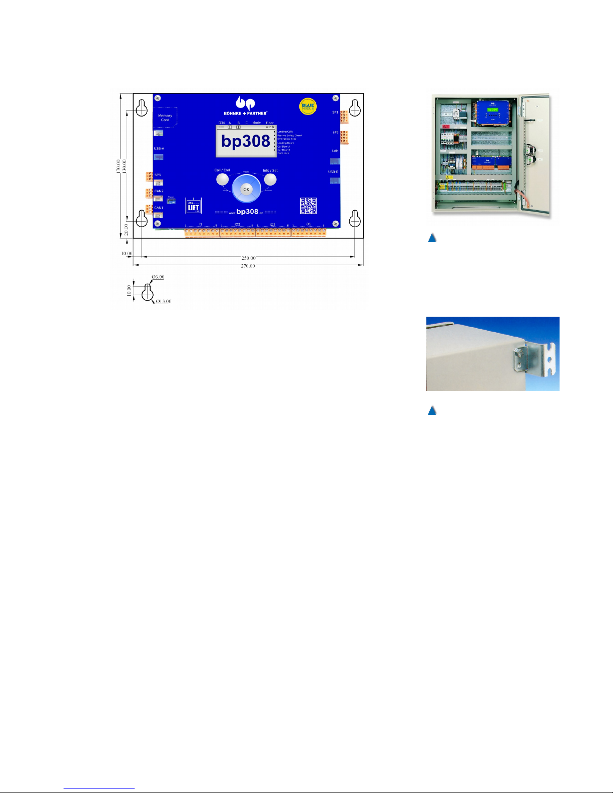
6.3 Installation of the Controller System bp308
The control system bp308 is supplied on an aluminium base plate. It
has got four drill holes for fixation. The plate may be fixed through
these holes only.
6.4 Installation of the Control Cabinet
BÖHNKE + PARTNER supplies your lift control unit in a control cabinet. According to your requirements it is either wall-mounted or
standing on the floor. Please fix your control cabinet as per the
instructions enclosed.
6.5 Assembly of the Car Terminal Box
The terminal box on the car is to be fixed in a way that you can easily
and safely reach the inspection control switch and possibly available
sockets and properly insert the travelling cable.
6.6 Assembly of the Absolute Encoder
The absolute encoder places the absolute position and speed of
the car at the disposal of every bus participant. It can be mounted
either in the shaft head or on top of the car. A toothed belt provides a
non-slip connection to the car. The unit may also be mounted at the
speed governor. In this case, the toothed belt does not have to be
used, but a magnet switch is to be inserted for correcting the slippage.
Please fix your control cabinet as per the instructions enclosed.
47
Fig. 25
The control system is supplied
in a cabinet, which is either
wall-mounted or standing on the
floor.
Fig. 26
Wall-mounted cabinets are
equipped with fishplates on the
back for fixing to the wall.
Page 47
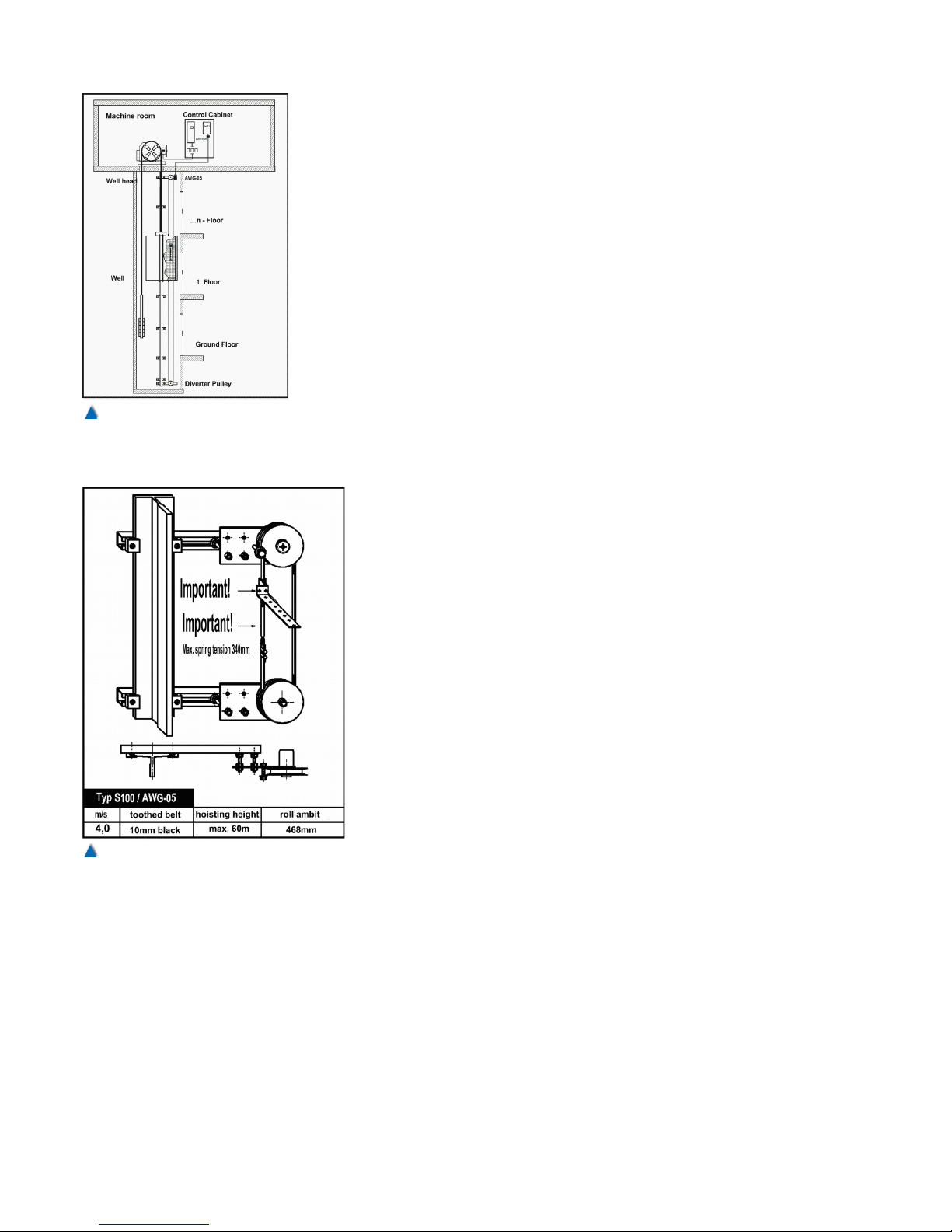
6.6.1 Fixation Kits for Absolute Encoder
There are different fixation kits available for the different ways of
mounting the absolute encoder in the shaft or on the car.
Typ S 100
Absolute encoder type AWG-05 with fixation kit in the shaft, comprising big toothed reel 10 mm wide, jagged flanges, suitable for travel
heights of up to max. 60 m and speeds of up to max. 4.0 m/s
Product no.: 287-051-003
Typ K 105
Absolute encoder type AWG-05 with fixation kit on car, comprising
big toothed reel 10 mm wide, jagged flanges, suitable for travel
heights of up to max. 180 m and speeds of up to max. 4.0 m/s
Product no.: 287-051-004
Toothed Belt
Z 10s, 10 mm, jagged flanges, black, for S 100, K 105
Product no.: 3020-130-100
6.6.2 Assembly in the Shaft
The absolute encoder is mounted to the guide rail in the shaft. It
is driven by a toothed belt with a non-slip connection to the car via
a deflection pulley.
48 Installation Manual System »bp308« – Installation and Commissioning
Fig. 27
The absolute encoder is driven
by a non-slip toothed belt.
Fig. 28
Fixation kits for mounting in the shaft
(Type S100).
Page 48
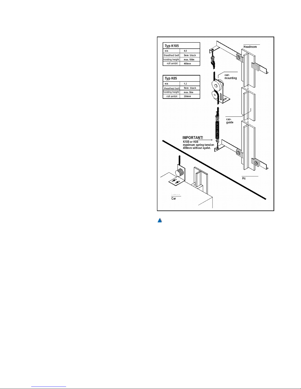
6.6.3 Assembly on the Car
A variant of the above-mentioned mounting is the
mounting of the absolute encoder on the car. A
toothed belt tightened from the shaft head down
to the shaft pit drives the absolute encoder. On
one hand you have got the advantage of a shorter
toothed belt, on the other hand the disadvantage
that the toothed belt may generate a rolling sound
when the toothed reel runs along at high speed.
This can however be reduced by a special layer
on the belt pulley.
49
Fig. 29
Fixation kits on the car.
Page 49
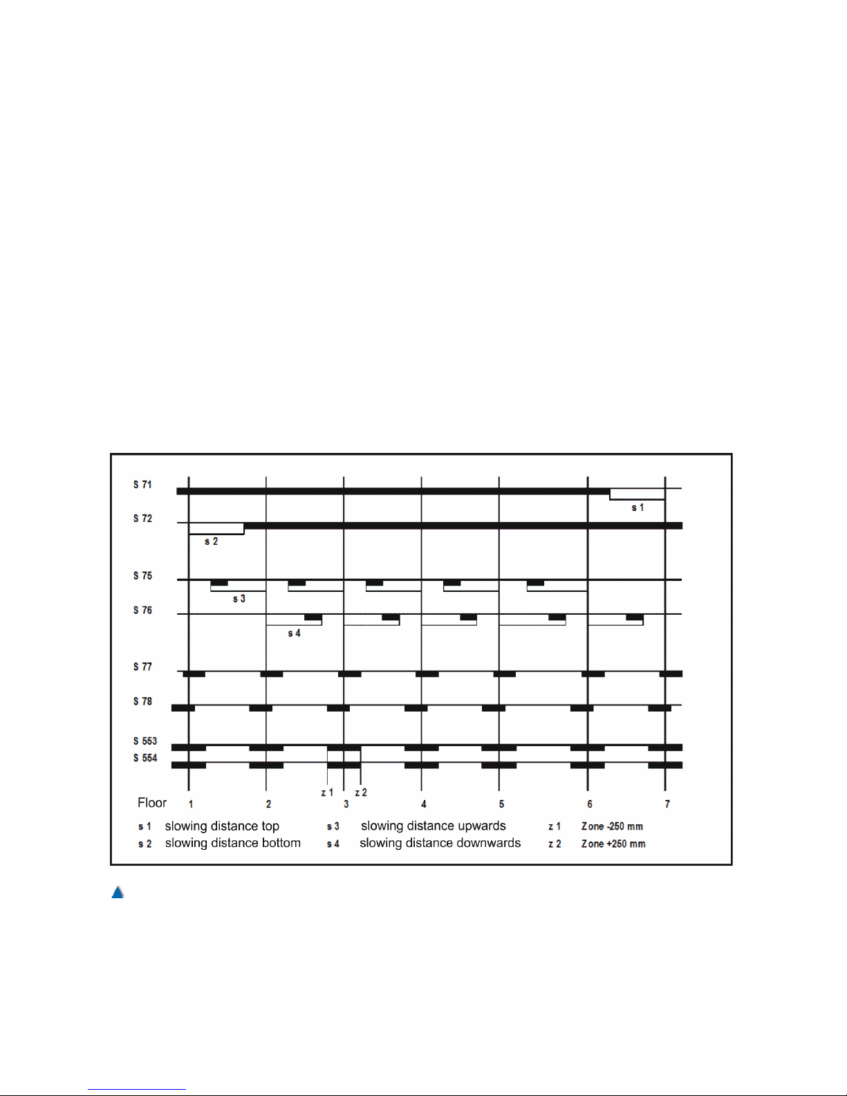
6.7 Assembly of the Magnet Switches
If magnet switches are to be used, they are to be mounted on the car
in a way that they pass by the magnets at a distance of approx. 5 mm
while the car is travelling through the shaft.
Definition of the Switches:
S71 Correction switch top Normally closed
S72 Correction switch bottom Normally closed
S73 Re-levelling switch up Normally open
S74 Re-levelling switch down Normally open
S75 Impulse up Normally open
S76 Impulse down Normally open
S77 Level position switch up Normally open
S78 Level position switch down Normally open
S553 Zone switch "A" Normally open
S554 Zone switch "B" Normally open
50 Installation Manual System »bp308« – Installation and Commissioning
Fig. 30
Example of a pulse diagram with magnet switches.
Page 50

7 Electrical Installation
7.1 Preparation
Prior to installing and commissioning this unit carefully read the
safety instructions and warnings and pay attention to every warning
label attached to the unit. Make sure that the warning labels are readable at all times and replace missing or damaged labels.
ATTENTION! DANGEROUS VOLTAGE !
• Make sure that the devices you work on do not carry current! Dis-
connect the system from the power (according to the circuit dia-
gram.
• Before carrying out any work on the lift control, ascertain that it
does not carry any voltages of > 50 V AC .
• Plugs must not be inserted in sockets as long as the according
devices are not switched off.
• Pay attention to the rules concerning the handling of delicate elec-
tronic printed circuit boards (protection against electrostatic
charges)!
• Before connecting the device to the power supply, check whether
the indications on the type label of the lift control correspond to the
values of the connected load.
• All electrical installations must comply with the general installation
regulations, including:
1. VDE 0100 Bestimmung für das Errichten von Starkstromanlagen
mit Nennspannungen bis 1000 V (rules for the installation of
power engineering systems with nominal voltages of up to 1000
V, from the association of German electrical engineers).
2. DIN EN 50178 (VDE 0160) Ausrüstung von Starkstromanlagen
mit elektronischen Betriebsmitteln (equipping power engineering
systems with electric operating resources, from the association of
German electrical engineers).
3. Legal regulations for the prevention of accidents, such as for
example BGV A2.
4. Legal regulations for the prevention of accidents, such as for
example BGV A2.
• If the lift control unit or related components are used in special
environments (e. g. ex-area), it is to be ascertained that the relev-
ant standards and regulations are adhered to.
• If the lift control unit is fitted with an uninterruptable power supply
(UPS), it is not be sufficient to disconnect the power to the unit with
the main switch; the UPS has to be turned off separately.
51
Page 51

7.2 Interference Suppression and Hints
All industrial, electronically controlled devices, such as, for example,
PCs, microprocessors, computers, SPSs, can be influenced by interference pulses if they have not been protected accordingly. These
interference pulses can be caused by external appliances, such as e.
g. voltage fluctuations in the feed-line or control pulses of the power
parts in the frequency inverter. BÖHNKE + PARTNER have taken all
usual measures while manufacturing the control unit. The installed
components are only slightly sensitive to interferences from their
environment. The control units have been designed for applications in
industrial environments where a high degree of electro-magnetic
interference is to be anticipated. Operation without risk and interference can be generally warranted by proper installation. Should difficulties arise despite taking these measures, adherence to the following directives might prove useful. It might be particularly efficient to
earth the reference potential of the system (0 V) in the control unit, as
described below
INFO!
• BÖHNKE + PARTNER checks the entire lift control unit before
supplying it. We document the status of supply in the circuit diagrams and in the protocol of the setup and service menu.
• Each control unit comes with circuit diagrams and technical documentation clearly identified by the control unit number.
• All 24 V DC control signals (are galvanically isolated from the control electronics.
• The control unit is to be installed in adherence to our circuit diagrams.
• Control lines and bus lines must be laid in a different location to the
load lines.
• When installing the control unit, you must adhere to the technical
data that has been used during production according your order.
• Follow the EMC instructions given by the manufacturer of the frequency inverter at all times !
• Should you have any question concerning the EMC Directive
please ask our service team .
• Please also pay attention to the information concerning cable
shielding (section 7.3)
52 Installation Manual System »bp308« – Electrical Installation
Page 52

Please consider the following measures:
• The control system bp308 exclusively serves as an information
processing device within the lift control system. All control signals
are processed by positive circuitry or via the CAN Bus. The Safety
Regulations TRA and DIN EN 81 are not restricted by the electronic information processing.
• The control unit has been designed, manufactured and tested in
accordance with DIN EN 81 (TRA) and the VDE regulations. You
must adhere to the relevant regulations for the commissioning of
electric control unit and operating devices. You should also follow
the local lightning protection rules.
• Each control unit comes with circuit diagrams and technical documentation clearly identified by the control unit number.
• The mounting and installation instructions of third-party device
manufacturers must be followed exactly.
• To conform to the EMC Directives, you have to wire an appropriate
one-phase mains filter into the 230 V AC control circuit and connected signal circuit
• The control lines are to be laid separately from the load lines in
separate cable ducts. Crossing lines are to be laid at an angle of
90°.
• Control devices are always to be connected by applying choke, filter and shielded cables and according to the mounting and installation instructions of the manufacturer.
• Ensure that all the devices contained in the cabinet are properly
earthed via short earthing lines with large diameters that are all
connected to a mutual earthing point or earthing bus. It is of particular importance that every control device connected to an inverter
(e.g. a speed encoder) has short lines with a large diameter and is
connected to the same earthing point as the inverter itself. Preferable are flat lines (e.g. metal brackets) as they have a lower impedance at high frequencies.
• Use shielded or reinforced cables for load lines between drive unit
and inverter or control unit, and connect the shielding/reinforcement to the earth at both ends.
• Data lines (group, data remote transmission, printer connection,
etc.) are generally made from shielded cables. The shielding of
data lines should be connected to the earth at one end
• Mounting racks consist of zinc-plated sheet steel, enabling large
surface earth connection to all control components.
• Interference-proof structural elements improve resistance against
environmental interferences.
• The car is to be connected to the earth by the green/yellow line of
the travelling cable.
53
Page 53

• Idle lines of the travelling cable should be connected with one end
to the earth at the control cabinet
• The components of the control unit conform with the regulations of
DIN EN 81 (TRA) as well as VDE 0100 / 0101 / 0551 / 0660 and
BGV A2. The control cabinets conform to the installation standards
VDE 0660 / part 500.
• Mains and auxiliary contactors used in the control unit comply with
DIN EN 81 part 1, 13.2, (TRA 260.82) as well as VDE 0660, but at
least equipment class D3.
• Voltage fluctuations are permissible if they range within a tolerance
of +10% to -20% normally guaranteed by the utility company.
• Damages for malfunctions caused by an impermissible voltage rise
may not be claimed from the manufacturer.
• If owners add further coils (inductivities) at their own discretion, it is
be of utmost importance that these coils are interference-proof as
well.
• DC-powered inductivities such as, for example, in contactors,
relays, brake magnets, lock magnets and hydraulic valves must be
equipped with a diode (1000 V / 1 A), anti-parallel and as near as
possible to the coil (BÖHNKE + PARTNER use a free running
diode).
• AC-powered contactors, relays, brake magnets, lock magnets and
hydraulic valves are required to be equipped with a RC combination pitched on the type of coil, in parallel and as near as possible
to the coil (the RC combination of BÖHNKE + PARTNER is universally usable).
• AC-powered door operators, braking and locking motors are to be
equipped with a RC combination pitched to the motor type, in parallel and as near as possible to the motor coil. The RC combinations are radially connected to the motor coil (the RC combination
of BÖHNKE + PARTNER is universally usable).
• Interference suppression means are to be properly installed.
54 Installation Manual System »bp308« – Electrical Installation
Page 54
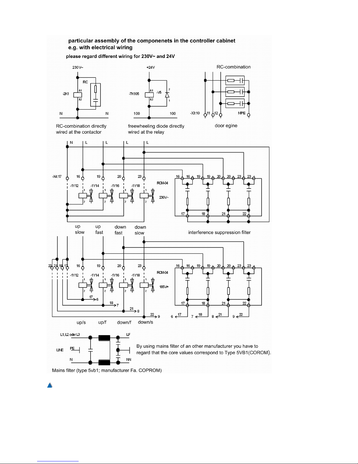
55
Fig. 31
Interference suppression circuit diagrams
Page 55
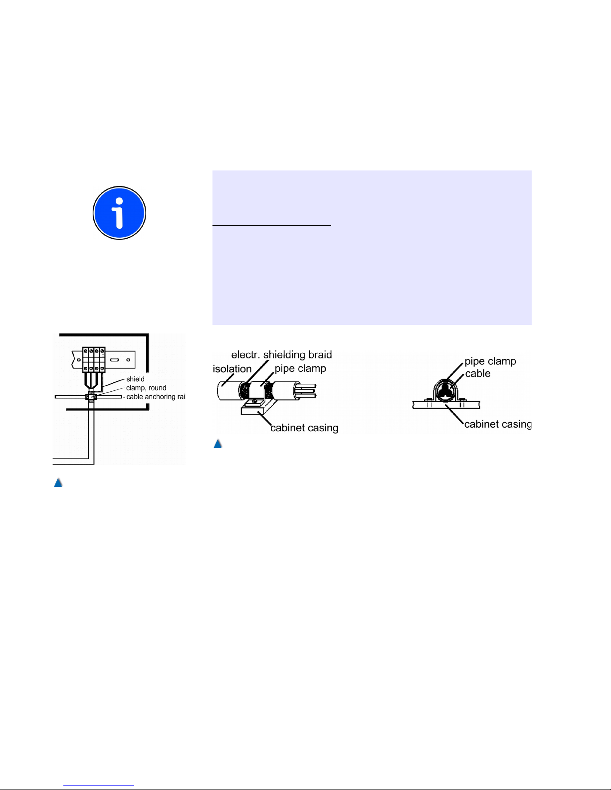
7.3 Connection of Shielded Cables
To achieve an optimal electro-magnetic compatibility (EMC) of the lift
system, all shielded cables have to be connected according to the following illustrations, provided that they have not been manufactured
as EMC plug connectors .
INFO!
It is not sufficient to twist the cable shielding and clip this »pigtail« to
PE potential. For a good EMC it is important to connect the shielding
always with its full surface .
If users connect further shielded cables at their own discretion, it is of
utmost importance that they connect them as shown in the illustrations!
Follow the EMC instructions given by the manufacturer of the frequency inverter at all times!
For any question concerning the EMC legislation please contact our
service team who will be pleased to advise you.
7.4 Designation of Circuit Diagrams
BÖHNKE + PARTNER define the different components in terms of
functional groups. We decided not to apply a fixed system when
naming the components. By preparing the circuit diagrams with a
CAD system, we achieve a high flexibility in designating the circuit
diagrams and parts lists. Each component is designated directly in
the circuit diagram with reference to function as well as project, i.e. in
a specific way for each customer.
Meanings of the abbreviations (functional groups):
A - Modules made by BÖHNKE + PARTNER, inverters
B C - Separate condensers
56 Installation Manual System »bp308« – Electrical Installation
Fig. 32
Example of the connection of a
shielded cable
Fig. 33
The shieldings are to be connected with their full surface to the PE potential by a cable or pipe clip.
Page 56

D - Diodes (e.g.: free- running diodes of DC relay )
E - Illumination (230 V AC – 240 V AC [e.g.: E5 = cabin light])
F - Fuses (e.g.: F2 = control fuse)
G - Incremental encoder, tacho generator (analogue, digital)
H - Analogue signals, visible and audible (6 V DC - 24 V DC [e.g. H7
= alarm buzzer in the shaft])
I J K - Main and auxiliary contactors, relays (e. g.: K1= mains contactor
up)
L - Chokes, coils
M - Motors, fans
N - Mains filter
O P - Digital indicators
Q - Motor protection switch
R - Resistors (e.g.: R5 = positive temperature control thermistor)
S - Switches
T - Transformers (e.g.: T2 = control transformer)
U V - Rectifiers
W X - Terminals, terminal strips
Y - Magnets (brakes, locks, valves)
Z -
Examples of designations in circuit diagrams:
2K5 contactor K5 on page 2 ...
4S71 switch S71 on page 4 ...
On page 2... (e.g.: page 21) a »star« may be found as a designation
together with the corresponding contactor symbol, thus defining contactor K5 as a star contactor .
On page 4... (e.g.: page 40) »correction up« may be found as a designation together with the corresponding switch symbol, thus defining
switch S71 as a »correction switch up«.
The CAD software used by BÖHNKE + PARTNER prevents the
duplication of designations.
Safety Circuit
INFO!
Once the safety devices are activated they prevent the lift from starting when called and/or stop a travelling car immediately .
The safety circuit was designed to monitor the following external signals:
57
Page 57
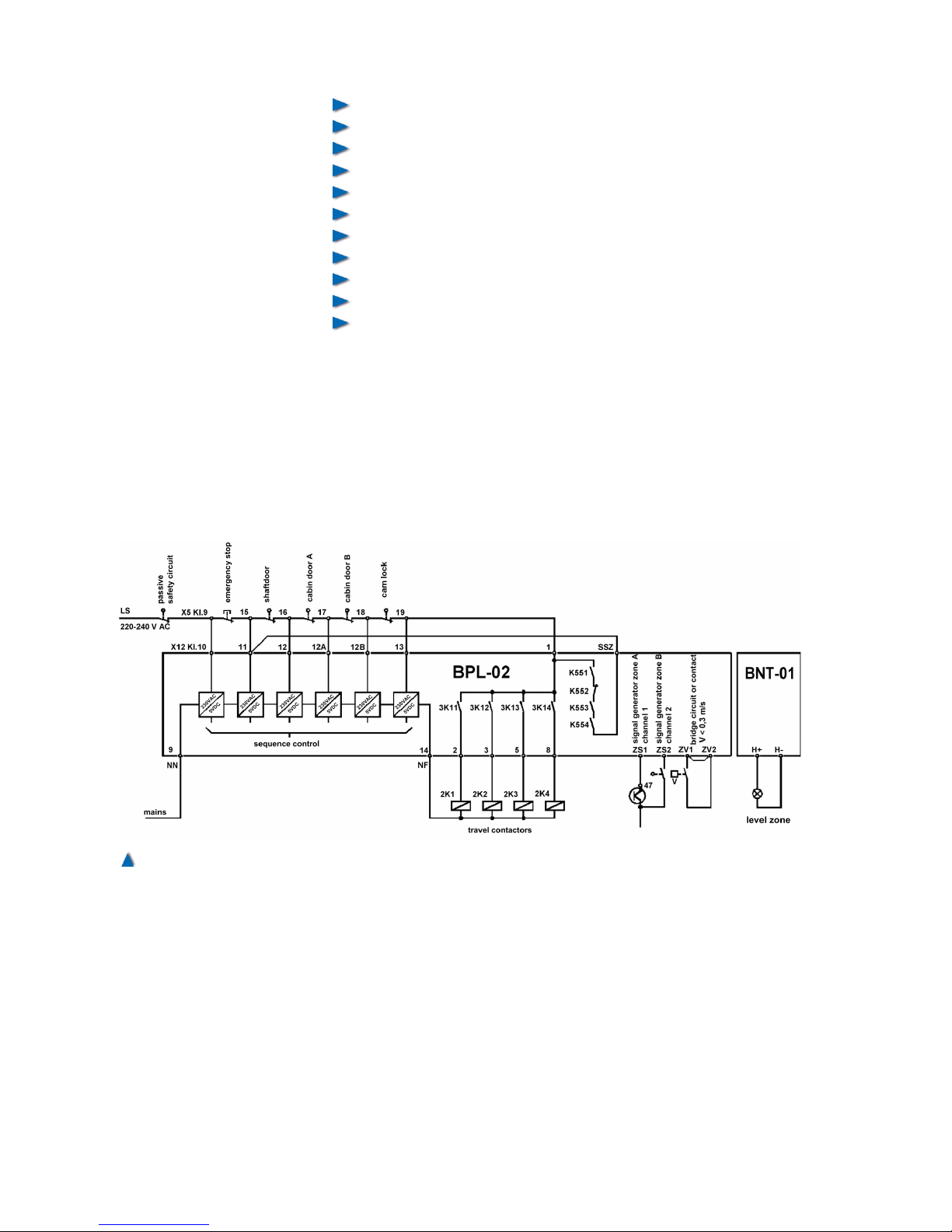
Closed position of maintenance door and emergency exits,
Locked status of car doors,
Locked status of landing doors,
Closed position of landing doors,
Closed position of car doors,
Emergency stop switch on top of car, in car, in machine room ,
Speed governor,
Buffer contacts,
Emergency limit switches top and bottom,
Safety gear,
Landing door zone with safety circuitry.
Doors and locks are monitored within the landing door zone, while
the car is approaching the landing with door starting to open and
while it is relevelled.
Every travel contactor and auxiliary contactor of the safety circuit is
laid out according to VDE 0660, device class D3. The safety circuit
has a signal voltage of 220-240 V AC.
The safety circuit functions are independent from those of the control system bp308. In case of a malfunction, the operational voltage
of the output module for control elements is cut off.
58 Installation Manual System »bp308« – Electrical Installation
Fig. 34
Standard arrangement of a safety circuit related to bp308
Page 58
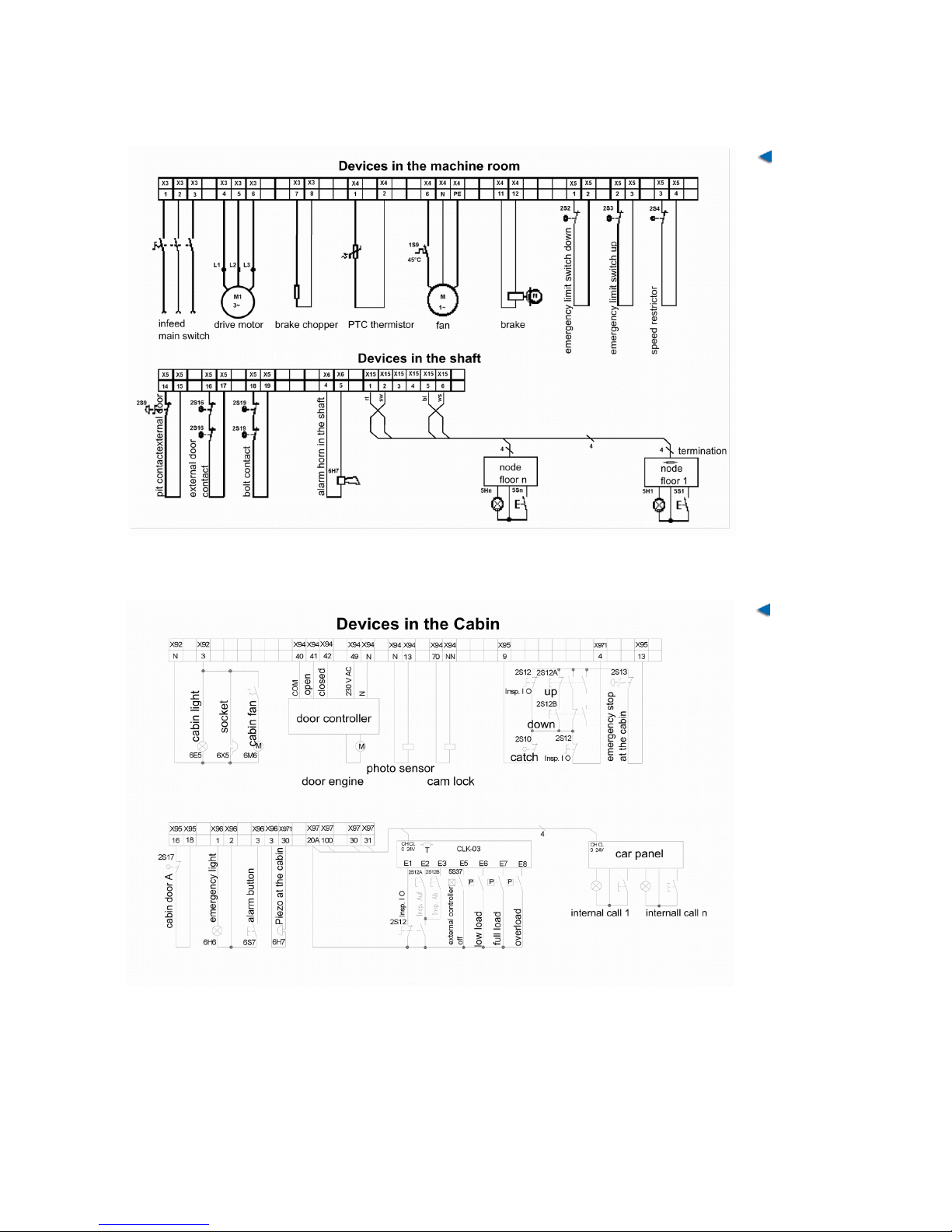
7.5 Sample Circuit Diagram of a Rope Traction lift
59
Fig. 35
Wiring of the
machine room
Fig. 36
Car wiring
Page 59
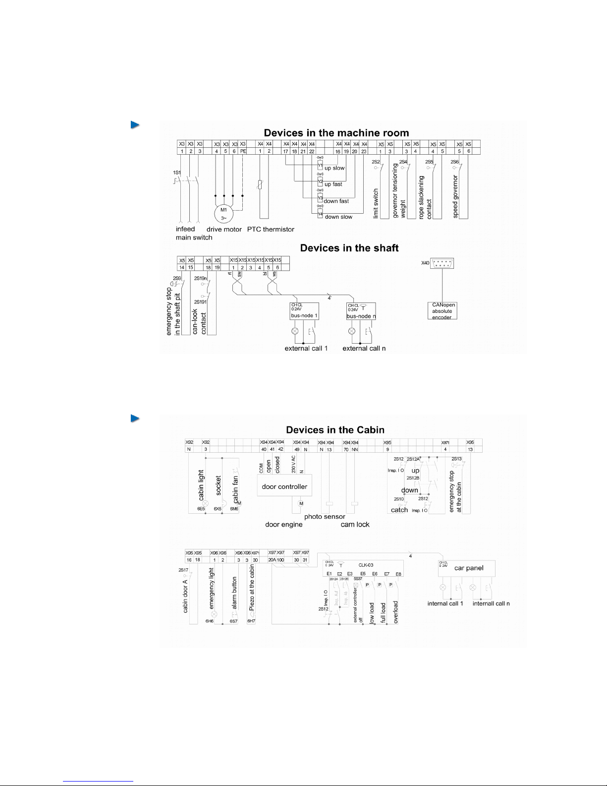
7.6 Sample Circuit Diagram of a Hydraulically
Operated lift
60 Installation Manual System »bp308« – Electrical Installation
Fig. 37
Wiring of the machine
room
Fig. 38
Car wiring
Page 60
7.7 Electrical Installation
After having mounted all components, proceed to their electrical
installation according to the circuit diagrams. Properly connect all the
terminals and adhere to the EMC wiring directives.
7.8 Bus Connection
The lift control systems bp308 comes with the CAN Bus according to
application profile CiA-417. This profile describes the physical parameters of the bus lines as well as the topology. There are generally
special rules for the wiring of bus systems.
7.8.1 Electrical Bus Medium
The components corresponding to CiA-417 require a two-wire data
communication line. Speaking in bus-terms, the components connected are denominated as nodes. Nodes are connected to the bus in
parallel. It must be ascertained that the topology of the bus line
always forms a line. The CAN high speed standard (ISO99-2)
requires both ends of the bus to be terminated with a resistor (120
Ohm) each. These terminations can be implemented in different
ways. It is possible within some nodes to activate an internal resistance via a DIL switch or jumper, in other ones a resistor is to be connected to the bus terminals. Read in the relating manuals of all connected nodes how to realize the termination!
The driver modules used restrict the maximum amount of nodes
per bus to 64. If more nodes are required, it is necessary to use repeaters or gateways (read further down).
Furthermore, all nodes connected must have identical
baud rates. The baud rate is preset to 250 kBit by network master bp308 at the interfaces CAN1 and CAN2.
All the other components made by BÖHNKE + PARTNER are equipped with an automatic baud rate identification or have been preset to a baud rate of 250 kBit.
Due to the baud rate used, length of the bus must not
exceed 250 m. Stub lines to the nodes must keep
below 3 m length.
61
Fig. 39
lift components that correspond
to the application profile CiA417 may be carry this logo .
Fig. 40
The bus ends must be terminated each with a resistor of 120 Ohm.
Page 61
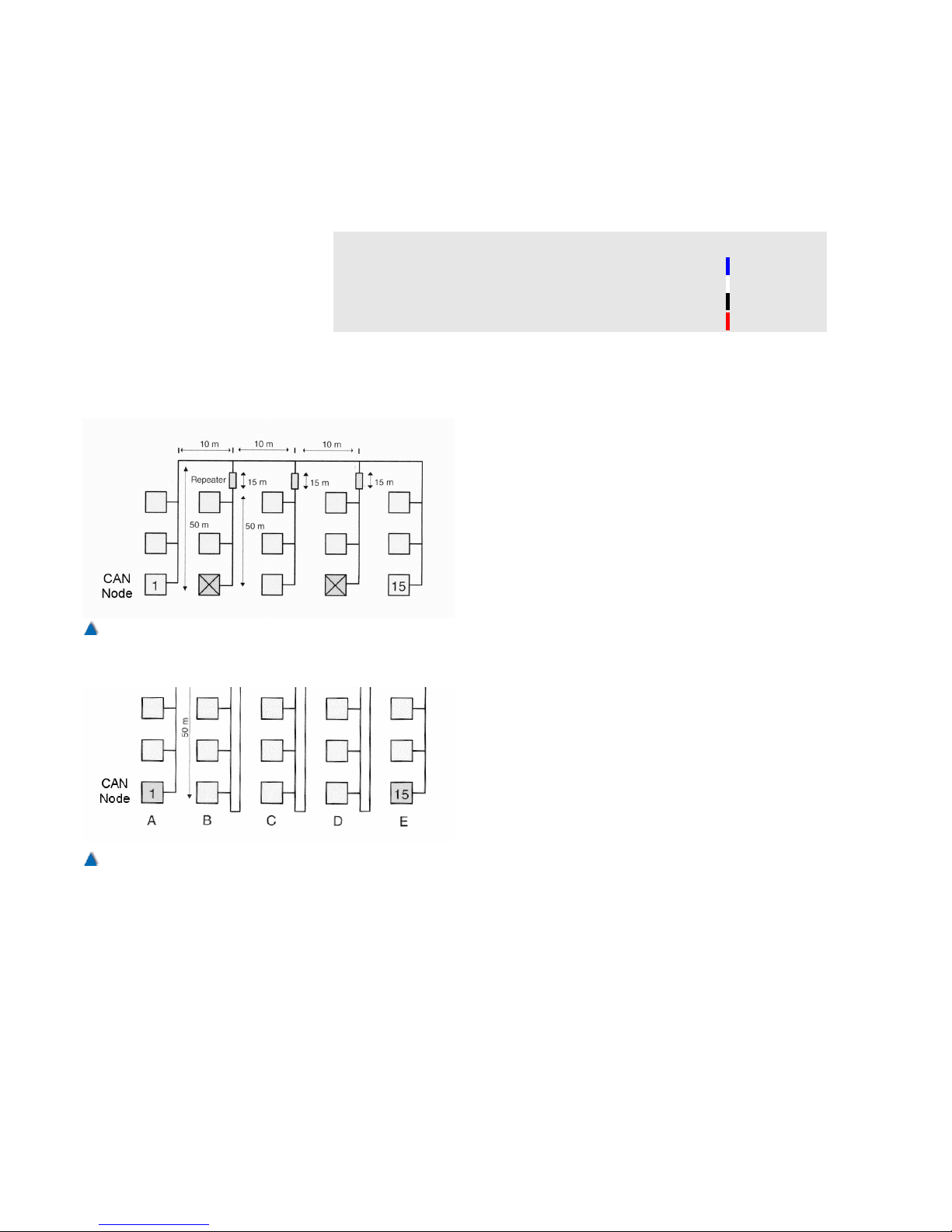
7.8.2 Colours of the Cables
CANopen does not pre-define the colours of the bus lines. To facilitate wiring and fault-finding, we recommend the following colours for
the bus lines:
Signal Description Colour
CAN_L CAN-Bus-Signal (dominant low) Blue
CAN_H CAN-Bus-Signal (dominant high) White
GND
External electrical ground
Black
CAN_V+
External voltage supply (+24 V)
Red
7.8.3 Topology of the Network
Owing to laws of physics within a bus system, a
topology is required. A line structure is specified
for the CAN-bus by CiA-417.
This line structure cannot always be realised in
practice. Therefore it is possible to connect further lines via repeater or gateway. Please note
that every line behind a gateway or a repeater is
to be regarded as an independent bus and consequently properly terminated at both ends
62 Installation Manual System »bp308« – Electrical Installation
Fig. 42
Nodes are always to be wired in line.
Fig. 41
Additional lines are connected by the use of repeater or
gateways
Page 62
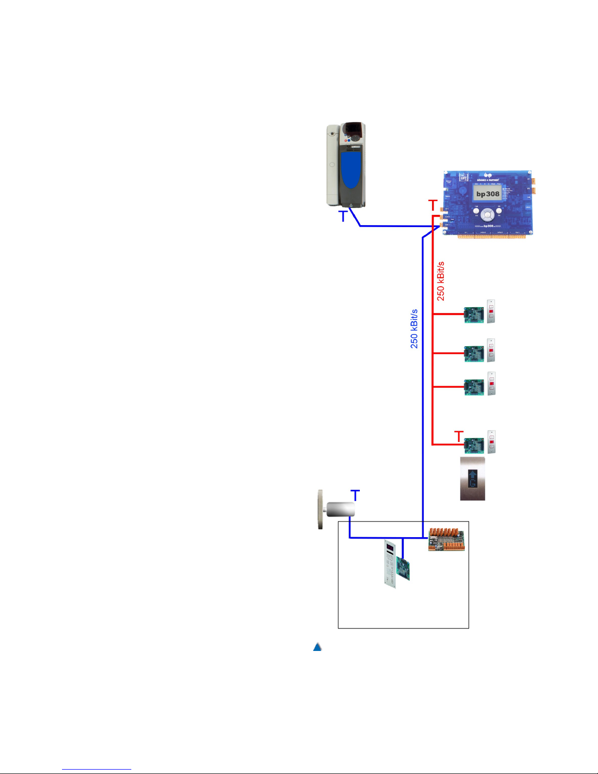
7.8.4 Example of a Correct Topology
7.8.4.1 Control Unit of an lift Out of a Group
From the picture you can see the line structure
and the terminations of the control unit of an lift
out of a group. The car bus is blue and group bus
red. Provided that the stub line to the inverter is
shorter than 3 m, termination can be realised at
the bp 308 as well. Termination on the car is
done by means of a connected absolute encoder
or a DIP switch (DIP 2 set to "on") on the CLK-
03. Termination of the group bus at the end of
the well is normally realised by activating the termination on the DIP switch of the last CAP-01/02
(DIP 2 set to "on").
63
Fig. 43
Sample of the topology of a single lift .
Page 63
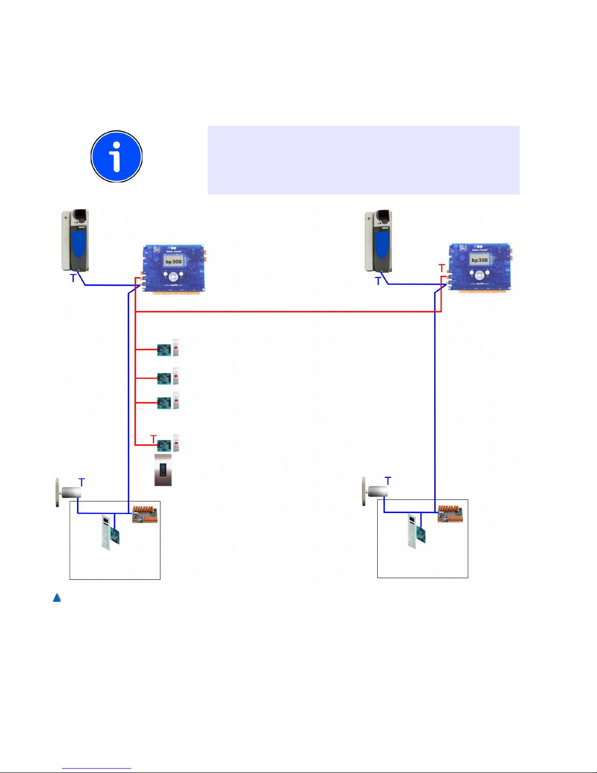
7.8.4.2 Group of Two lifts in One Line
On the picture you can see the topology of a bus for the landing calls
of a group of two lifts in one line. This is also a line structure with
properly terminated ends
INFO!
Pay attention to the terminations while commissioning the lift. In most
cases, a lift is first put in operation as a single unit and the connection
to the group is realised later on. In this case, the terminations are to
be adapted (refer to controls of a single lift ).
64 Installation Manual System »bp308« – Electrical Installation
Fig. 44
Topology of a group of two lifts in one line only.
Page 64
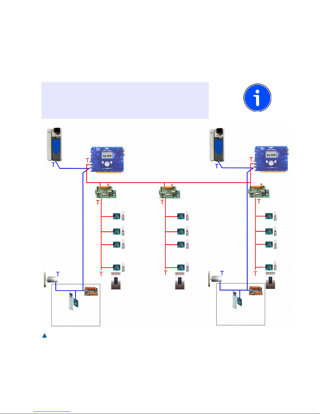
7.8.4.3 Group of Two lifts in Three Lines
On the picture you can see the topology of a bus for the landing calls
of a group of two lifts in three lines. As the line structure cannot be
realised for more than two lines, gateways are used in order that
each single line forms a real line itself. The bus is terminated at each
end.
INFO
Pay attention to the terminations while commissioning the lift. In most
cases, a lift is first put in operation as a single unit and the connection
to the group is realised later on. In this case, the terminations are to
be adapted (refer to controls of a single lift).
65
Fig. 45
Topology of a bus for the landing calls of a group of two lifts in three lines.
Page 65

7.8.4.4 Group of Two lifts in Two Lines
In the picture you can see the topology of a bus for the landing calls
of a group of two lifts in two lines. The line structure is given by the
terminations at both ends of the shaft.
INFO
Pay attention to the terminations while commissioning the lift. In most
cases, a lift is first put in operation as a single unit and the connection
to the group is realised later on. In this case, the terminations are to
be adapted (refer to controls of a single lift).
66 Installation Manual System »bp308« – Electrical Installation
Fig. 46
Topology of a group of two lifts in two lines.
Page 66
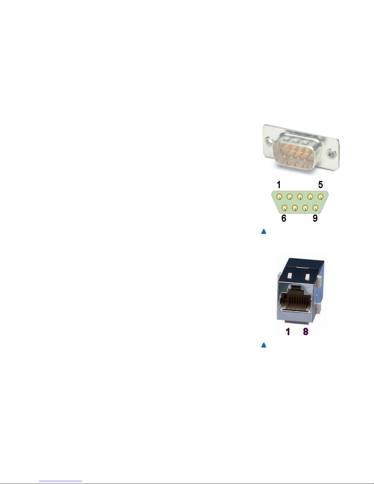
7.8.5 Pin Assignments
The CANopen standard stipulates the pin assignments of the most
common plug connectors. The application profile for lifts recommends the following plug connectors for lift components:
• D-Sub 9pins
• RJ45
• Open-style-plug connector
7.8.5.1 Pin Assignment of D-Sub Plug Connector with 9 Pins
Pin Signal Description
1
- Reserved
2
CAN_L CAN-Bus-Signal (dominant low)
3
CAN_GND CAN electrical ground
4
- Reserved
5
CAN_SHLD Optional shielding
6
GND Optional electrical ground (from pin 9)
7
CAN_H CAN-Bus-Signal (dominant high)
8
- Reserved
9 CAN_V+ Optional external power supply
(+24 V)
7.8.5.2 Pin Assignment of the RJ45 Socket Connector
Pin Signal Description
1 CAN_H CAN-Bus-Signal (dominant high)
2 CAN_L CAN-Bus-Signal (dominant low)
3 CAN_GND CAN Ground
4 - Reserved
5 - Reserved
6 CAN_SHLD Optional shielding
7 GND Optional electrical ground (from pin 9)
8 CAN_V+ Optional external power supply
(+24 V)
67
Fig. 47
D-Sub-Stecker 9pins
Fig. 48
RJ45-socket connector
Page 67
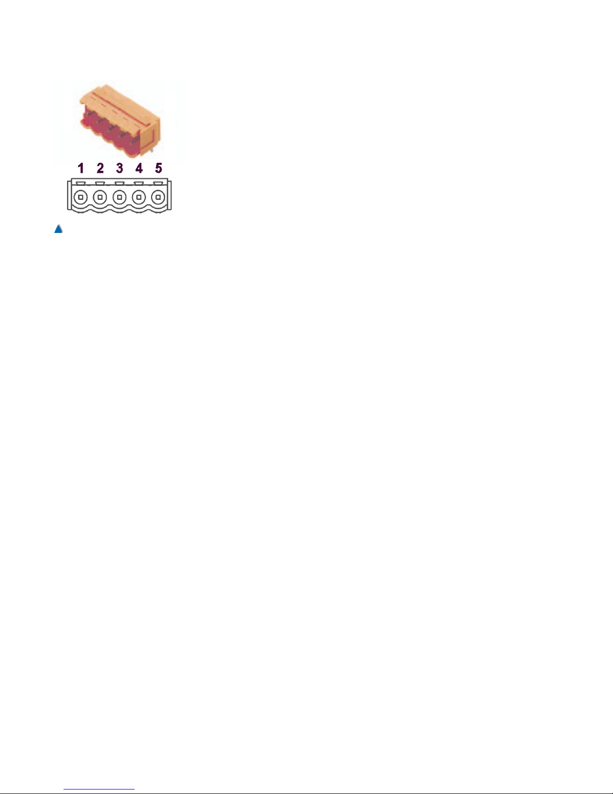
7.8.5.3 Pin-Assignment of the Open-Style-Connector
Pin Signal Description
1 CAN_GND CAN electrical ground
2 CAN_L CAN-Bus-Signal (dominant low)
3 CAN_SHLD Optional shielding
4 CAN_H CAN-Bus-Signal (dominant high)
5 CAN_V+ Optional external power supply
(+24 V)
7.8.6 Node IDs of the CAN Components
Every CANopen component can be identified by a node ID that must
be unambiguous within the CANopen network. If there are two components with identical ID connected to the bus, they cannot be selected by the system.
BÖHNKE + PARTNER assigns the node-IDs according to the
recommendations of the SIG lift control (www.CANopen-
Lift.org/wiki/Node-IDs) as per the following scheme.
Node-ID
[dec.]
CAN1
Local bus
CAN2
well bus
1 bp308 - lift control unit bp308 – lift control unit G1
2 Drive unit (frequency inverter) bp308 – lift control unit G2
3 Reserved bp308 – lift control unit G3
4 Sensor/positioning 1 bp308 – lift control unit G4
5 Sensor/positioning 2 bp308 – lift control unit G5
6 Door control 1 (door A) bp308 – lift control unit G6
7 Door control 1 (door B) bp308 – lift control unit G7
8 Door control 1 (door C) bp308 – lift control unit G8
9 CDG-01 – Gateway CDG-01 – Gateway 1
10 Reserved CDG-01 – Gateway 2
11 Reserved CDG-01 – Gateway 3
12 CLK-03 - car terminal box CDG-01 – Gateway 4
13 Load-measuring device CDG-01 – Gateway 5
14 Emergency call unit CDG-01 – Gateway 6
15 Reserved (emergency call unit) CDG-01 – Gateway 7
16 Cabin push button unit node 1 CDG-01 – Gateway 8
17-20 Cabin push button unit node 2 - 5
21-70 CAP-01/02 - landing call units landings 1 to 50 (e.g. line 1 or door A)
71-120 CAP-01/02 - landing call units landings 1 to 50 (e.g. line 1 or door B)
125 Default node ID (preset of inventory components such as CAP-01/02 or CIO-01)
126 Flash update bootloader
BÖHNKE + PARTNER supply the lift control unit with all node IDs
already present.
68 Installation Manual System »bp308« – Electrical Installation
Fig. 49
Open-style-plug connector 5
pins
Page 68

7.9 Travelling Cable to the Car Top Box
The car terminal box is connected by a travelling cable type
16G0,75+8x(3xAWG22)+3x(2xAWG22) C 4.7x79.1 sw. Please read
the assignment of the wires from the enclosed circuit diagrams.
Wire Terminal Function
1 X92:4 Socket of terminal box
2 X92:LN Neutral conductor light
3 X94:48 Photocell 230 V AC + power supply of door side A 230 V AC
4 X94:58 Photocell 230 V AC + voltage supply of door side B 230 V AC
5 X94:NN(N) Neutral conductor controls + door sides A and B
6 X95:9 Feed line to passive safety circuit of safety gear contact
7 X95:11 Üridging of passive safety circuit of emergency control unit
8 X95:13 Return line from emergency stop
9 X95:16 Feed line to door contact
10 X95:17 Return line from door contact side A
11 X95:18 Return line from door contact side B
12
13
14
15
gr/ge PE Electrical ground
Violet X96:1 Emergency cabin light (switch to negative )
Green X96:2 Positive voltage of feed line to emergency light and alarm button
Blue X96:3 Return line from alarm button
Violet X97:20A Voltage supply 24 V DC
Green X97:20A Voltage supply 24 V DC
Orange X97:100 Voltage supply 24 V DC
Violet X97:100 Voltage supply 0 V DC
Green
Darkgreen
Violet
Green
Brown
Violet
Green
Grey
Violet
Green
White
Violet
Green
Red
Violet
Green
Black
White X96:10 Telephone a
Blue X96:11 Telephone b
Shielding Electrical ground Shield terminal
69
Page 69

Wire Terminal Function
White X912:a SLP 485 a
Orange X912:b SLP 485 b
Shielding Electrical ground Shield terminal
White CAN_H
Darkgreen CAN_L
Shielding Electrical ground Shield terminal
7.10 Selection of the Frequency Inverter
There are three possibilities to select the frequency inverter with the
bp308. Depending on the type of inverter, the unit can be selected by
means of the CAN Bus, the DCP interface or by wiring in parallel with
the controller/pre-control module RVM-01.
7.10.1 Selection by CAN Bus
If your inverter has got a CANopen interface according to the application profile CiA-417, you should interconnect it with bp308 via the
CAN Bus. This way of selecting the inverter is the least complex as
regards installation and configuration due to the fact that the standardised application profile enables plug-and-play to a certain extent
as well as excellent diagnostics.
Connect the inverter to the CAN1 connector of bp308 according to
the circuit diagrams enclosed. Lay the cables and terminate the bus
lines in compliance with the instructions of section 7.8.4.
7.10.2 DCP-Connection to the Inverter
The DCP interface serves as a serial connection between lift control
unit and inverter. It is an RS485 point-to-point connection.
The DCP interface is put on the top 3-pole plug connector on the
left side of the BPC in bp308. The pin assignment is given in the following table.
7.10.2.1 Pin Assignment of DCP Plug Connector
Pin Signal Description
5 COM Electric ground of the signal (optional )
6 B Signal line RS485 inverted
7 A Signal line RS485
Connect the signal lines to the corresponding terminals of the
inverter. Optionally, you can connect the electric ground of the signal
(please refer to manufacturer’s manual of your inverter). The cable
should be twisted and shielded. The shielding is to be installed on
70 Installation Manual System »bp308« – Electrical Installation
Page 70
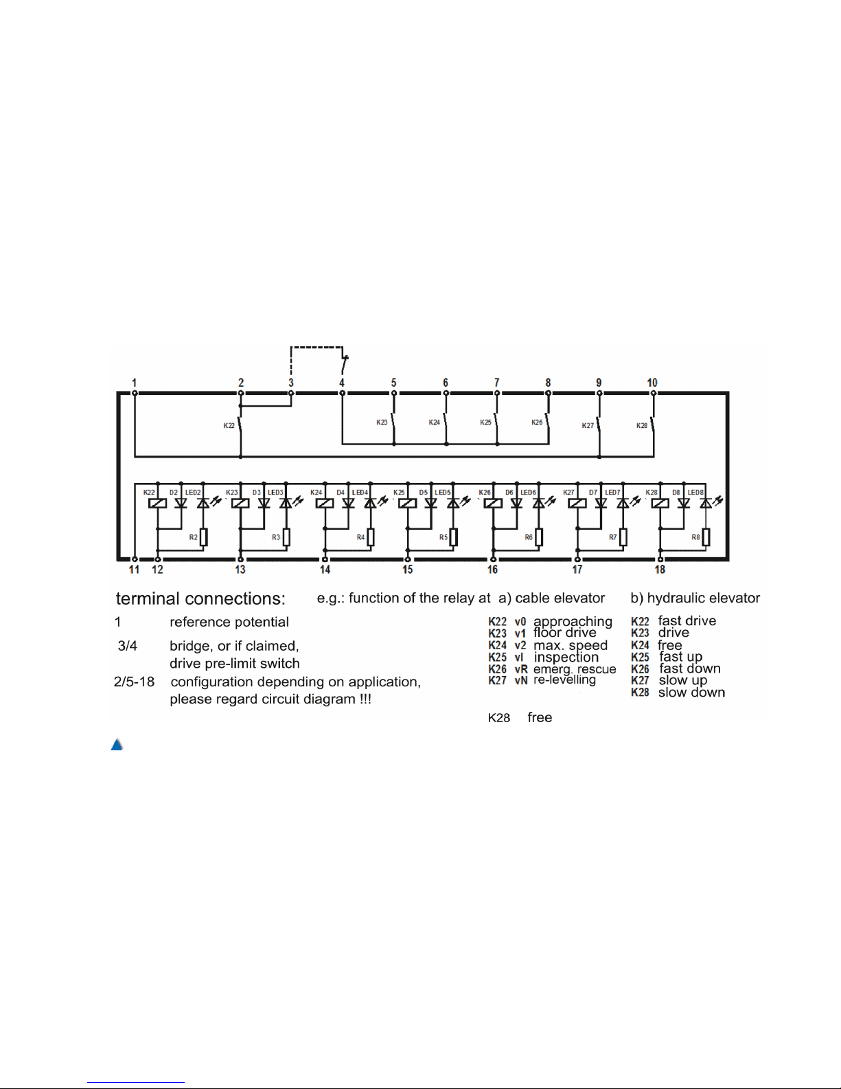
one side of the inverter only. Ensure a full-surface connection (refer
to section 7.3).The maximum cable-length for the DCP connection is
600 m.
7.10.3 Wiring in Parallel with RVM-01
The controller/pre-control module »RVM-01« selects all known inverters that do not feature the option of a serial interface. The control signals for the different speeds and directions of travel are put out via 7
potential free relays equipped with gold-plated double contacts to
ascertain reliable switching for every possible demand on the
inverter.
71
Fig. 50
The circuitry of the RVM-01 module.
Page 71
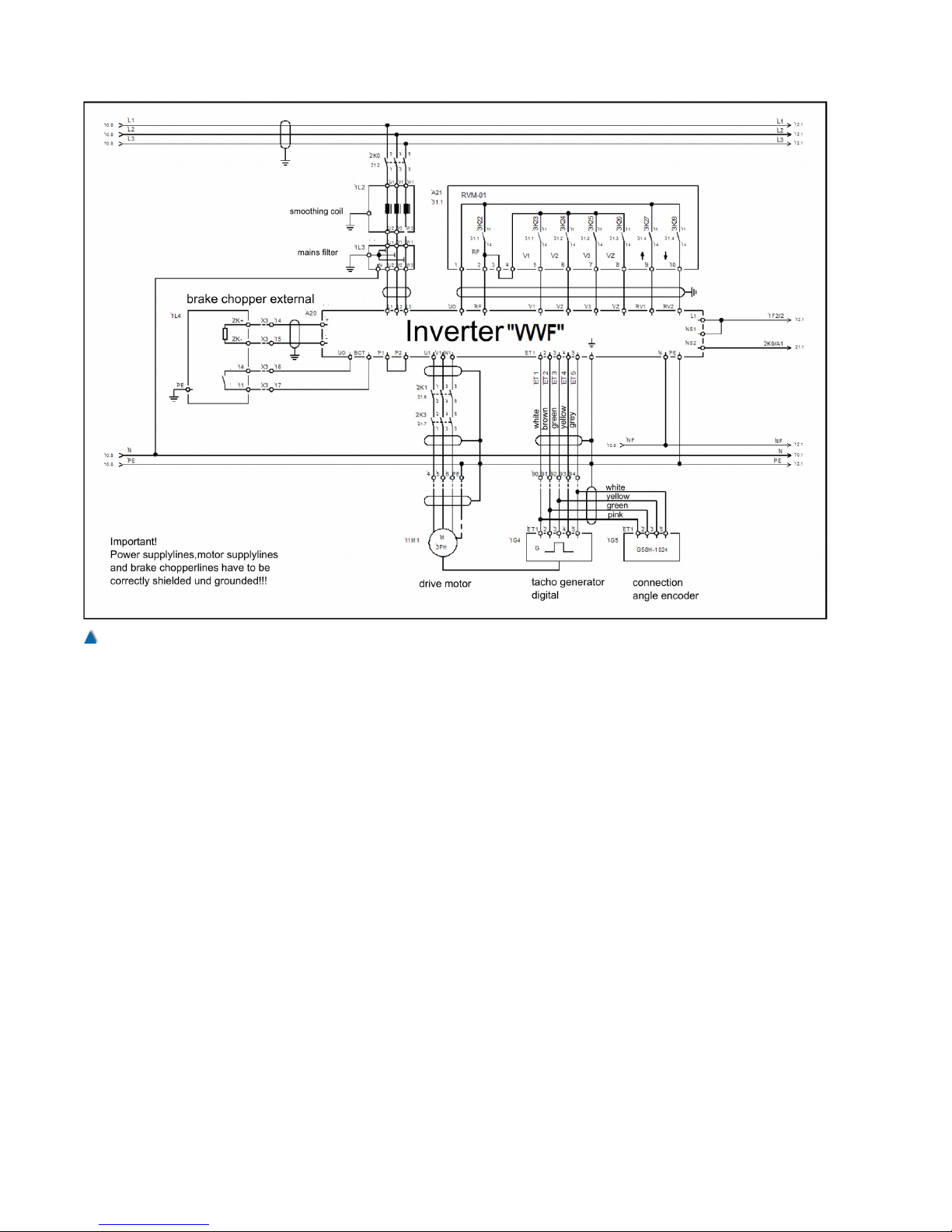
Control inputs (example)
GND Reference potential
UO Control voltage of the inverter
voltage output selecting the inputs
RF Controller enabling, to be in selected status during travel .
V1 Fine positioning speed
V2 Levelling speed
V3 Travel speed
VZ Re-levelling speed
RV1 Direction default 1 UP
RV2 Direction default 2 DOWN
Provided that the inverter has been connected according to
the switching circuit suggestion, the factory preset motor
turns left if input »RV1« is activated and right if »RV2« is
activated (as seen from the motor side of the shaft.
ZE1 Additional speed V_ZE1
ZE2 Additional speed V_ZE2
72 Installation Manual System »bp308« – Electrical Installation
Fig. 51
Example of a selection of the inverter by RVM-01.
Page 72
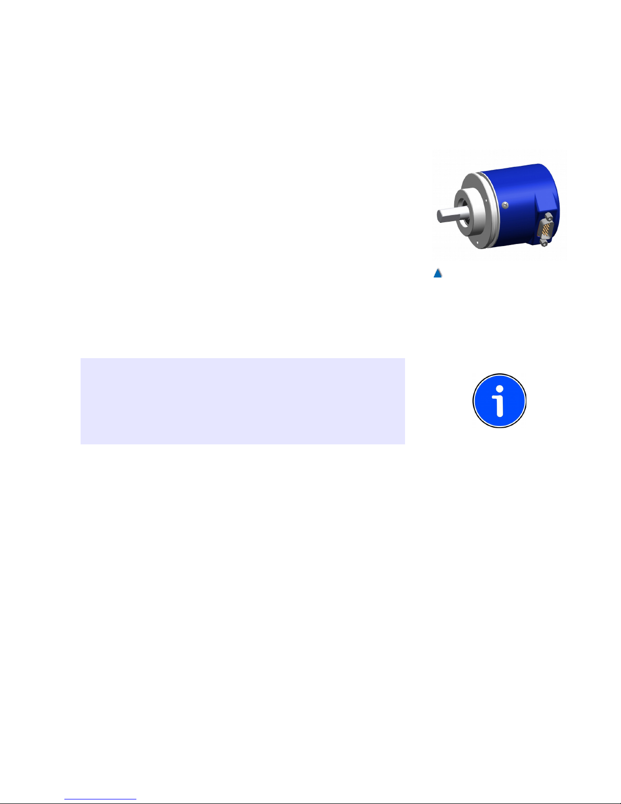
Preferably, these additional speeds are to be used for
inspection and emergency operations.
ZE3 Additional speed V_ZE3
This input may activate different functions of the inverter, to
be preset in the menu INTERFACES. The additional speed
V_ZE3 was selected a factory.
BCT Brake chopper temperature. At this input, you can monitor
the temperature switch or the malfunction output of the brake
chopper.
7.11 Installation of the Absolute Encoder
The absolute encoder is equipped with a 9-pin D-sub plug, the
assignment of which conforms with the CANopen standard. The CAN
Bus is terminated in the AWG-05 CANopen (type GXP5W.Z06 ).
If the absolute encoder has been mounted on the car, its connect-
ing cable can be plugged directly into the socket on the CLK.
If the absolute encoder is installed in the shaft head, its connecting
cable can be plugged into the respective socket in the control
cabinet.
INFO
Some types of position systems always terminate the can bus. If the
position system is mounted and connected on the car, termination via
the DIP switch 2 has to be deactivated on the CLK-03. You can find
information on terminating devices in their accompanying manuals or
online at www.CANopen-Lift.org
7.12 Interconnection of the Group
By means of the interconnection of the group, the lift control units
communicate with each other and transmit the well signals.
The connection »CAN2« serves as an interface for the interconnection of the group. The data lines must be twisted. They lead from the
terminals of the BPC to the terminal strip of the lift control unit. Connection to the other members of the group is given by a plug connector
The lines of the well signals are connected to the group as
described in the »Topology« section. If the shaft signals have been
connected to the control units in a conventional manner, they are
translated into CANopen data by components such as.
73
Fig. 52
The absolute encoder AWG-05
CANopen (type: GXP5W) can
be mounted in the well head or
on the car.
Page 73
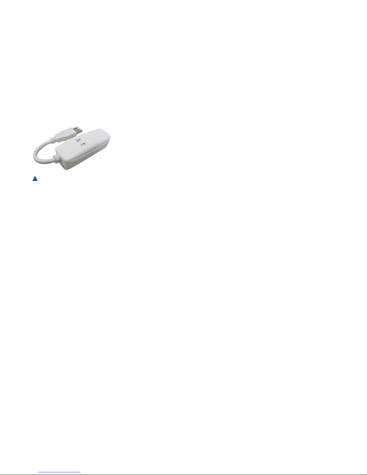
7.13 Data Lines to the Remote Diagnostics
System
Remote diagnostics can be realized via different mediums, each subject to different rules.
7.13.1 Analogue Telephone Line
If remote diagnostics are to be carried out via an analogue telephone
connection, the data is transmitted via an analogue modem, which
can be connected to the USB-A slot of the BP308. This has to be a
"real" hardware modem and not a software modem. The USB
modems for the bp306 supplied by BÖHNKE + PARTNER are "real"
hardware modems. The modem must also support the V.250 standard. If more than one control unit is allocated to a joint telephone outlet or if there is an emergency call system that uses this analogue
telephone outlet as well, you have to use an emergency call manager
(refer to the "Connection of the Emergency Call System" section).
7.13.2 ISDN
If there is an ISDN connection available for the data remote diagnostics, the integrated ISDN module (option ISDN) is used or an
external ISDN interface.
7.13.3 Ethernet
If data remote diagnostics is to be carried out via an Intranet or the
Internet, an Ethernet interface is usually available in the machine
room. Use the integrated Ethernet module of the bp308 in this case .
74 Installation Manual System »bp308« – Electrical Installation
Fig. 53
56K Hardware USB modem,
e.g. from LONGSHINE, US
Robotics or MANHATTAN
Page 74
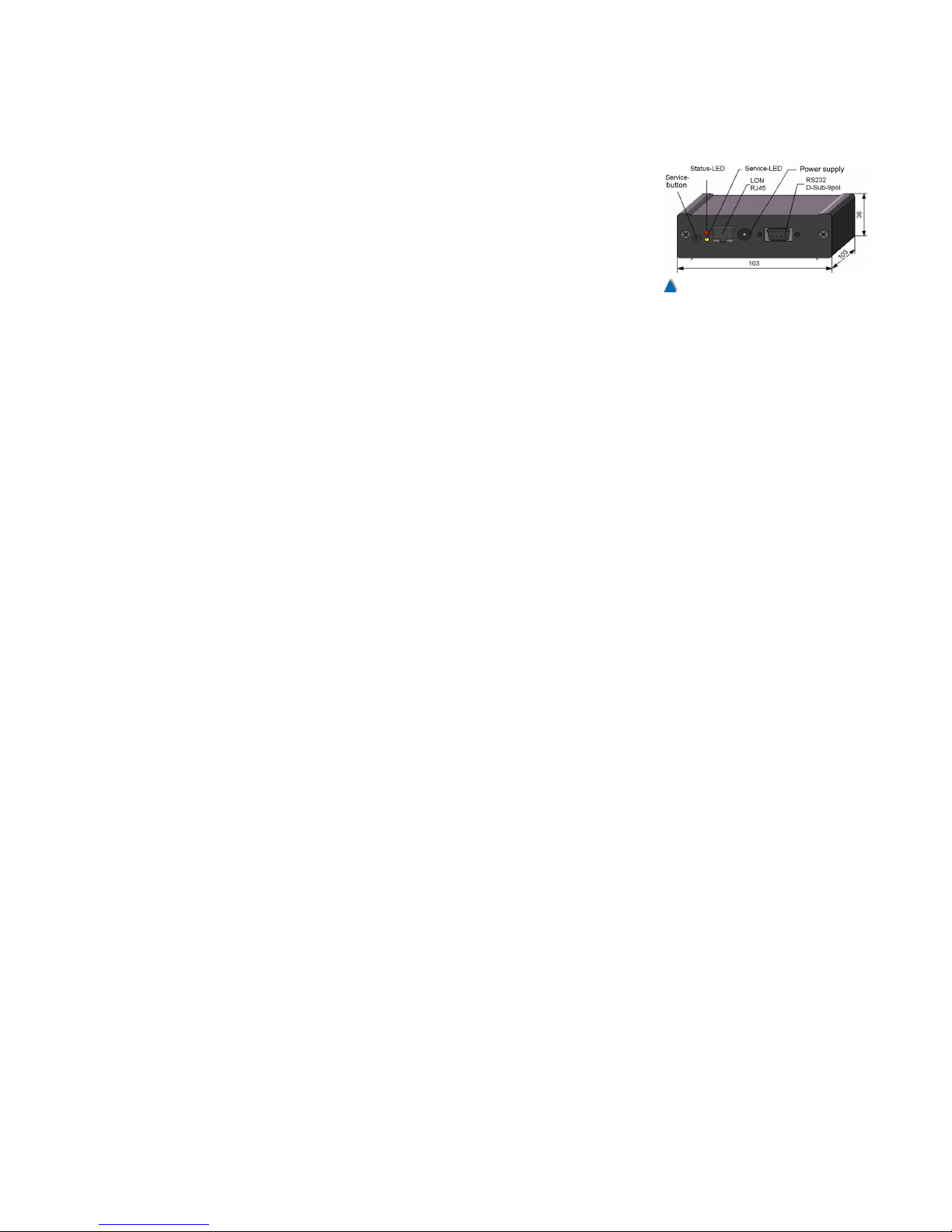
7.13.4 LON
Connection to a LONworks network – e.g. within the building automation system – is carried out via the ASBuP interface. It is connected
to the optional SP1 connector of bp308 as well as a RJ45 plug to the
LON network.
7.14 Installation of the Emergency Call System
Emergency call systems mostly require analogue telephone connections. If a separate analogue connection is available especially for the
emergency call system, wiring can be implemented as specified for
the emergency call system. Most of the time, however, the emergency call system and the modem of the control unit have to share
one telephone line. In this case, it has to be ascertained that the
emergency call system is given priority. Some emergency call systems place a through-connected extension at the disposal of a data
remote monitoring system as long as no emergency call is at hand. If
there is no such extension available on the emergency call system, a
so-called emergency call manager has to be applied that interrupts
an existing connection to the data remote monitoring system in case
of emergency and renders the freed telephone connection available
to the emergency call system.
Generally there is no valid scheme of how to install an emergency
call system. Please read the circuit diagrams and documentation concerning the emergency call system, which you can find enclosed.
75
Fig. 54
The LON-Interface ASBuP for
connecting the lift to a LONworks network.
Page 75
8 Commissioning Instructions
ATTENTION!
The control systems of BÖHNKE + PARTNER and the drive system
must not be commissioned before having fulfilled the following conditions:
• The control unit has been mounted and installed according to this
manual.
• Operating and setting possibilities are all known (see user manual
bp308 ).
• The valid EMC rules (electro-magnetic compatibility) are complied
with!
• The power circuit, control circuit and safety circuit have been con-
nected and checked according to this manual (see check-list).
• Instructions that also have to be followed when commissioning the
system:
- First Travel with Emergency Controls (section Fehler: Referenz
nicht gefunden),
- First Travel with Inspection Controls (section Fehler: Referenz
nicht gefunden),
- First Travel with Normal Operation Controls (section Fehler: Referenz nicht gefunden) and
- Commissioning of the Floor selector System (section Fehler: Referenz nicht gefunden).
INFO!
You must read the supplementary instructions prior to commissioning
any specially designed systems and components.
After commissioning, the actual parameters must be documented in
the printout of the setup and service menu or an up-to-date printout
has to be saved to a storage medium (memory card, USB stick). Malfunctions stored during commissioning (malfunction stack
memory/malfunction list) can be deleted in the sub-menu »diagnostics«. If third persons have access (e.g. janitor), protect the
menus against unauthorised access by using a setup and a service
code number (minimum four digits).
CAUTION!
Prior to each travel the operator has to ascertain that neither persons
nor property are endangered.
The final inspection and approval must be carried out in compliance
with the »Technical Tips« (Section Fehler: Referenz nicht gefunden).
77
Page 76
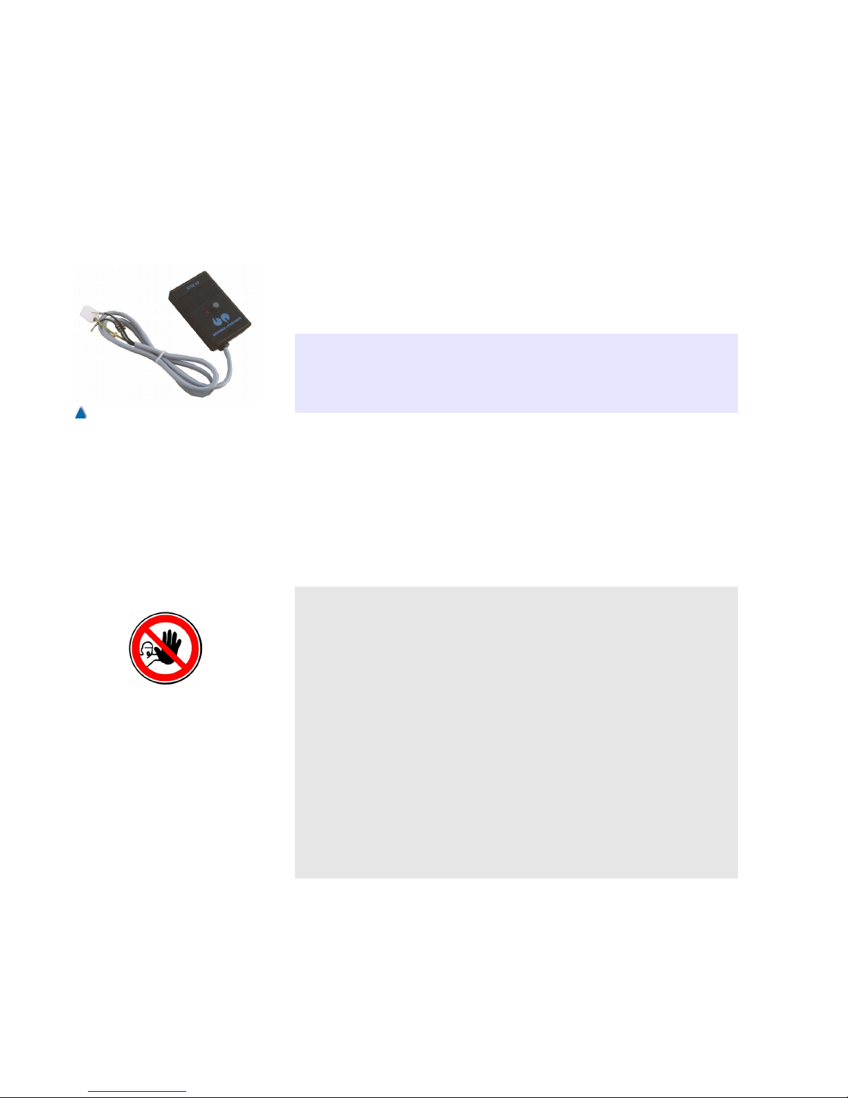
8.1 Preparation
No special measuring instruments are required for commissioning on
site except a multimeter. It is recommended to use the voltage test
module STM-02.
8.2 Voltage-Test Module STM-02
To protect your lift control unit against damage from excess voltage
while installing or repairing it, use the voltage test module STM-02
especially designed for this purpose.
INFO!
For monitoring purposes, integrate the voltage test module in the
control unit for the time of commissioning. Remove it as soon as
commissioning is finished. You can use it for further operations.
8.2.1 Prior to the First Switch-on
According to VDE 0100 (standard from VDE (association of German
engineers) and TRA (German Safety Regulations for lifts), the control
circuit has to be earthed. For that reason, the »PE«-terminal of the lift
control unit is connected to terminal 100 of bp308 by a green/yellow
conductor.
CAUTION!
Make sure that the lift system does not carry any voltage!
• Disconnect the green/yellow protective earth conductor from terminal 100 of bp308. The negative potential of the control circuit
now must not have any contact with the PE potential of the control
unit at any point whatsoever in the lift system.
• You must therefore ascertain before connecting the STM-02 device
that there really is no connection between the PE terminal of the lift
control unit and terminal 100 of bp308. Use an Ohm-meter or a circuit continuity tester.
• After having completed these checks, you can connect the voltage
testing module STM-02 as shown in the diagram enclosed. Connect conductor 1 to terminal 100 in bp308 and conductor 2 to terminal 20A of the terminal strip in the control unit.
Now you can start your installation or repair work.
78 Installation Manual System »bp308« – Commissioning Instructions
Fig. 55
Voltage-test module STM-02. It
protects the control unit against
over-voltage.
Page 77
8.2.2 Functional Description of Voltage Test
Module STM-02
As soon as STM-02 has been installed properly, the control circuit 24
V DC is not earthed. With the lift system switched on, any overvoltage within the control circuit towards »PE« does not result in a
fault current, removing the risk of bp308 components being destroyed
.
CAUTION!
• STM-02 signalises over-voltages in the control circuit with an LED
and a buzzer. At that moment, there is danger in the area of the
control voltage.
• If STM-02 signalises a fault, switch the lift off at once, find the fault
and eliminate it.
The fault message is stored by a bistable relay and remains in
memory even if the control voltage is switched off and on again. To
reset the unit to its original mode after rectifying a fault, press the
reset button on the casing of STM-02 .
CAUTION!
• Immediately after finishing all work, connect the green/yellow PEline to terminal 100 within bp308 again!
• Remove STM-02 from the control unit.
8.3 Technical Tips Concerning the Control Unit
5. Error-free and safe operation of the product is subject to appro-
priate transport, storage, erection and installation as well as to
careful operation and maintenance.
6. The control unit has been designed, manufactured and tested in
accordance with DIN EN 81 and the VDE regulations. You must
adhere to the relevant regulations for the commissioning of electric control unit and operating devices. You should also follow the
local lightning protection rules. Each control unit comes with circuit diagrams and technical documentation clearly identified by
the control unit number.
7. The control system bp308 exclusively serves as an information
processing device within the lift control system. All control signals
79
Page 78

are processed by positive circuitry. The safety rules DIN EN 81
are not infringed by electronic data processing.
8. The control system bp308 was examined by the relevant authorities and has been awarded an EC type examination certificate. In
section “Product Certifications” you can see this EC type examination certificate and in section 3.3 the declaration of conformity
according to the EC Directives (95/16/EC) stating that the component applied conforms to the regulations.
9. The components of the control systems conform with DIN EN 81
as well as VDE 0100 / 0101 / 0551 / 0660 and BGV A2. The control cabinets conform to the installation standards VDE 0660 /
part 500.
10. Mains and auxiliary contactors used in the control systems comply with DIN EN 81 part 1, 13.2 as well as VDE 0660, but at least
equipment class D3.
11. Voltage fluctuations are permissible if they range within a tolerance of +10% to -20% normally guaranteed by the utility company .
12. Damages for malfunctions caused by an impermissible voltage
rise may not be claimed from the manufacturer.
13. Particularities related to the use of an uninterruptable power supply unit (UPS) are to be observed. First read the according operation before commissioning connected UPS as the unit has to
provide a safe power supply to all necessary control functions.
Regularly check the uninterruptable power supply unit with regard
to proper functionality and error-free operation .
Adhere to the instructions of the unit’s manufacturer .
14. Isolation and short-circuit measuring:
1) Since 1 January 1996, every control unit has been equipped
with an attenuation filter that might, however, be damaged while
measuring the isolation. Ensure that fuse 1F2 is switched off prior
to measuring the isolation in the safety circuit.
2) Any uninterruptable power supply unit integrated in the control
unit has to be disconnected completely and the contacts bridged
accordingly in the control unit before measuring the isolation and
short-circuits .
3) Adhere to the safety instructions applicable to isolation measuring as there is danger to you and the equipment .
15. All relays and contactors integrated in the control system must
be radio-shielded.
80 Installation Manual System »bp308« – Commissioning Instructions
Page 79

16. In-built motor protection switch, over-current release, current-operated circuit breaker etc. have been set at factory and have to
be individually adapted to the appliances connected by you while
commissioning the control system .
17. According to the respective operation instructions, the following
wiring instructions are to be followed:
Conductor N (N) to terminal 9 of bp308.
Conductor N (N) to terminal 14 of bp308.
18. According to VDE-rules and TRA 200, the signal voltage (minus
24 V DC) is to be connected to the protective earth conductor
(PE) of the mains supply .
- Terminal 100 (minus 24 V DC) of bp308 is to be connected to
the PE terminal in the control unit, thus avoiding a floating network and making it possible to recognize an earth leakage of the
signal voltage (+24 V DC) at once .
- Transformers are connected to the earth at the secondary side
(e.g. special voltage of brake or valve) thus avoiding a floating
network and making it possible to recognize an earth leakage of
the secondary voltage at once.
19. Terminals 20A and 20C (+24 V DC max. 2.2 A) of bp308 are
monitored with regard to overload and short-circuit. Overload is
signalised by the LCD.
20. Safety circuit and query-unit of bp308 are fused at max. 1 A.
21. Pay attention to the control pulse-diagram. Presentation of the
pulse-lugs is not true to scale. It is just a schematical diagram .
22. Arrangement of the shut-down points in the landing area (landing
level zone) is to be observed precisely.
23. Signals from the pulse-generator and flush-level switches can be
monitored on the LC display in the service-menu, sub-menu well
signals, not only in the travel mode but also in the inspection control mode or emergency control mode.
24. It is possible to keep the car door closed at the landings during
maintenance and service activities. See service-menu, sub-menu
maintenance, on the LCD.
25. During checks, the car can be driven to the top or bottom landing
by activating the »Call« switch:
Switch up: car travels to top landing,
Switch down: car travels to bottom landing.
81
Page 80

26. In the inspection control mode, terminals 101 and 102 of bp308
and/or CLK-01 lose their current (see DIN EN 81, 14.2.1.3):
- All cabin and landing calls are deleted and blocked ,
- Doors cannot be opened, automatic door movement is disabled,
- High travel-speed is automatically reduced at the correction
switch,
- The travel is stopped at the flush-level switch of the terminal
landing,
- The re-levelling device is switched off,
- The homing function of hydraulically operated lifts is disabled.
- Emergency controls are disabled .
27. In the emergency control mode, terminal 102 of bp308 loses all
current :
- All cabin and landing calls are deleted and blocked, ,
- Doors cannot be opened, automatic door movement is disabled ,
- High travel-speed is automatically reduced at the correction
switch.
- The flush-level switch of the terminal landing can be over-travelled in the emergency control mode!
- See service-menu, sub-menu maintenance, on the LCD.
- The re-levelling device is switched off,
- The homing function of hydraulically operated lifts is disabled.
28. If the emergency control and inspection control are switched on
simultaneously, the car cannot be moved.
29. Switching the landing controls with switch S85 deletes all cabin
and landing calls, landing calls are blocked, but cabin calls are
still accepted.
30. If landing controls are switched off, the parking landing is also
ineffective.
31. Light voltage disruptions are monitored by the control unit. If it
fails, the moving car is stopped and remains at the landing with
open door.
Further travels are blocked .
If it is a hydraulically operated lift, it sinks down to.
the home landing. The inspection and emergency control.
remain operational as well as the re-levelling device (refer to DIN
EN 81, 8.17.3)
32. PTC monitoring uses positive temperature thermistors wrapped
up in the coil of the A.C. motor to protect the motor. The monitoring circuitry integrated in bp308 monitors the operating temperature of the motor.
33. Die PTC threshold values are monitored and processed by a follow-up circuitry.
a) Temperature normal value<2.2 kOhm = normal operation ,
82 Installation Manual System »bp308« – Commissioning Instructions
Page 81

b) Temperature too high value>2.7 kOhm = PTC thermistor has
responded, refer to fault messages
Settings in the setup menu:
Rope traction lift
Immediate stop without switch-off
Stop at next flush-level switch ahead without switch-off
Immediate stop with switch-off
Stop at next flush-level switch ahead with switch-off
Hydraulically operated lift
Stop with return without switch-off
Stop without return without switch-off
Stop with return with switch-off
Stop without return with switch-off
34. The error message concerning excess motor temperature is
stored in the batch memory and malfunction list. If the data
remote monitoring system is connected, it immediately reports
this malfunction to the service centre.
35. The homing function of hydraulically operated lifts to the bottom
landing during normal operation, i.e. all safety functions, are OK ,
a) If it is automatically initiated after the preset period (max. 15
min.).
b) If it is automatically initiated as soon as the control unit is
switched off. (e.g. remote switch-off).
c) If it is automatically initiated after the preset period (max. 15
min.) after switching off the landing controls.
• In all three cases [a), b), c)], the creeping correction system
remains operational (see DIN EN 81 part 2 , 14.2.1.5)
• When the car arrives at the bottom landing, the door opens
and closes in all three [a), b), c)] cases. The »door open« button
remains active at all times.
• The cabin light can be switched off in idle condition and with
the door closed; this function is adjustable to 1, 10 or 30 minutes.
The cabin light is switched on as soon as the lift resumes operation.
36. Activation of the top emergency limit switch of a hydraulically
operated lift shuts down the lift at once. If the car frees up again
through subsequent creeping, the normal functions remain
switched off and the car is returned to the bottom landing at once,
as long as the safety circuit is closed. The car door opens and
closes again and the car parks at the bottom landing and does
not accept any call. The »door open« button remains active at all
times.
37. The creeping correction system remains operational. (see DIN
EN 81 part 2 , 14.2.1.5)
83
Page 82

38. On hydraulically operated lifts, the creeping correction system is
activated as soon as the runtime monitoring is activated (terminal
42 = 1) and the lift is immediately shut down .
39. On hydraulically operated lifts, the anti-creep monitor is queried
as follows :
a) the up-creeping monitor automatically causes the car to be
returned to the bottom landing and shut down there. If the
runtime monitoring responds outside the landing area zone during this action, the lift is blocked at once and the creeping correction system is not activated as the first malfunction registered was
»up-creeping monitor«.
b) the down-creeping monitor causes the lift to be shut down at
once. The creeping correction system remains operational.
40. The creeping correction system remains operational if a hydraulically operated lift is overloaded.
41. The overload input is queried at standstill only (terminal 88).
42. The excess pressure switch of a hydraulically operated lift is connected to terminal 35 and queried at this terminal as well. The
basic menu offers − depending on the function − the option to
select or deselect shut-down in case of excess pressure. The circuit diagrams also remind you of this option
43. A hydraulically operated lift can principally be equipped with an
emergency circuitry down (similar to emergency circuitry »up
only«). If an emergency circuitry down is installed, the following
switches may be bridged: shortfall in pressure, pipe rupture, bottom limit switch and safety gear contact.
CAUTION!
A combined safety gear contact/slack rope switch must not be
bridged, nor any other switch. The following applies for the emergency circuitry »down«:
a) The bottom emergency limit switch must not bridged !
b) An emergency circuitry »down« must not be applied in lifts
with 2:1 suspension without slack rope switch!
ATTENTION!
Operating instructions and labels on the emergency circuitry unit
must inform about risks !
Example: A defective hydraulic hose or a defective threaded hose
coupling causes the hydraulic oil to be pumped into the shaft pit!
44. The hydraulically operated lift must conform to all stipulations set
out in the relevant local "water protection regulations"!
84 Installation Manual System »bp308« – Commissioning Instructions
Page 83

45. Runtime monitoring is a standard function in every lift control
unit. To check this function, proceed as follows (DIN EN 81, part
1, 12.10 and part 2, 12.12):
Floor selector using magnet switches
a) Stop the car at the bottom landing,
b) Disconnect pulse transmitter from S75 and S77,
c) Enter travel command to top landing ,
d) Car passes by the pulse transmitters without receiving the
necessary signals,
e) After the preset time interval (max. 45 s), the electronic monitoring device of the lift control unit automatically interrupts the
travel,
f) Afterwards, the lift control remains blocked for further travels
(see information on LCD),
g) Connect pulse transmitter again to S75 and S77,
h) Operate call button (call/end) and confirm with OK to unblock
the car; alternatively, switch the control unit off and on again.
i) The control unit is now operational again.
46. Floor selector using an absolute encoder
a) Make the car stop at the bottom landing,
b) Reduce the set runtime of the runtime monitoring in the control system (LC display) corresponding to the travel speed,
c) Enter travel command to top landing,
d) The car does not reach the next encoding point within the
runtime period,
e) After the preset time, the electronic monitoring function of the
lift control automatically interrupts the travel ,
f) Afterwards, the lift control remains blocked for further travels
(see information on LCD),
g) Set the runtime of the runtime monitoring in the control system (LC display) to a value corresponding to the travel speed,
h) Operate call button (call/end) and confirm with OK to unblock
the car; alternatively, switch the control unit off and on again.
i) The control unit is now operational again.
47. The creeping correction system of a hydraulically operated lift
remains operational, even if the runtime monitoring has responded .
ATTENTION!
48. The motor will be damaged if due to a phase failure (e.g. contact
problems of the travel contactors) the creeping correction system
(re-levelling) remains operational although the runtime monitoring
has responded .
85
Page 84
INFO!
1) We have preset the parametrisable program runs, time intervals, etc. of the control systems in the setup menu and the service menu according to the technical specification. to the local
requirements. While commissioning the lift controls, you must set
the parameters according to the appliances installed and conforming to the local requirements.
2) The company installing the equipment has the duty to exercise
care in setting the correct parameters. Pay attention to the local
regulations stipulated by the fire-fighting experts for fire brigade
lifts and fire emergency lifts.
3) The setup menu as well as the service menu can be blocked
by a 4-digit code. The codes protect the parameters from being
unintentionally reset and must be stored with utmost care. Disclose the codes to authorised persons only.
49. To safeguard the individual parameters of the lift, call up the
store system data parameters sub-menu in the setup menu under
various.
50. Conclude the setting by pressing the END button after having
entered the changes in the function menu of the LCD, then return
to the basic display of the LCD.
8.4 Checks before Starting the Control Unit
CAUTION!
• Work through this check-list after installing a new control unit or
refurbished an existing one.
• Only continue if you have answered the current question
with »Yes «.
Weight balancing between car and counterweight has taken place. Yes □
The mechanical brake has been adjusted. Yes □
The car is positioned at a sufficient distance from the limit switches
(minimum 1 m).
Yes □
Mains voltage of 3 x 400 V AC is available. Yes □
Buffers have been mounted and are functioning. Yes □
Speed governor and safety gear have been mounted and are func-
tioning.
Yes □
Safety circuit contacts of well and car have been mounted and
installed.
Yes □
Have you paid attention to the safety instructions in section 2
"Safety Information" and followed them ?
Yes □
86 Installation Manual System »bp308« – Commissioning Instructions
Page 85

The control unit made by Firma BÖHNKE + PARTNER comes with:
• circuit diagrams, unambiguously identified by the serial number
of the control unit (e.g.: : 93401)
• Parts lists,
EC type examination certificate and declaration of conformity for
System bp308,
• Terminal plans,
• Basic settings,
• Port assignment plans and general tips concerning the control
system bp308.
Are these documents complete?
Yes □
Have you followed the circuit diagrams that belong to the control
unit
Yes □
Have you paid attention to the safety instructions in section 7.2
'Interference Suppression and Hints" and followed them?
Yes
Have you checked that all terminal points are correctly and tightly
connected?
Yes □
Have you turned off the main switch ? Yes □
Have you connected the voltage test module STM-02 (see section
Fehler: Referenz nicht gefunden)?
Yes □
Check the voltage supply! Have L1, L2, L3, N and PE been properly
connected (clockwise rotating field)?
Yes □
Does the cross section of the conductors correspond to the power
draw of the lift system?
Yes □
If there is a load switch, have you checked whether the admissible
fusible elements are installed as well?
Yes
Is the automatic circuit breaker 1F2 for the control voltage switched
off?
Is the automatic circuit breaker 1F4 for the safety voltage switched
off?
Yes
Yes
Have the power supply lines been correctly fused? Yes □
If there is a quick activation circuitry available for the brake, have
the protection switches been turned on?
Yes □
The motor protection switch, over-current activator, FI protection
switch, phase monitor etc. installed in the monitoring unit can only
be pre-installed by BÖHNKE + PARTNER. When commissioning the
system, you have to set them to the values suiting the appliances
connected.
Have you set these values?
Yes □
Have all the PE conductors been connected properly? Yes □
Have you complied with all interference suppression measures and
EMC instructions of the frequency inverter manufacturer?
Yes □
Have you followed the commissioning instructions concerning speed
and drive controls?
Yes □
Has the emergency control unit been switched on? Yes □
87
Page 86

If you have answered »yes« to all these questions, you may switch in
the mains voltage according to the instructions in the following section.
8.5 Switching the Mains Voltage
If you have answered »Yes« to all the questions of the »Checks
before Starting the Control Unit«, you can switch the mains voltage
in. After that, check the items of the following check-list.
Have you turned on the mains switch?
Has the emergency control unit been switched on?
Yes □
Yes □
Is the automatic circuit breaker 1F2 for the control voltage
switched on?
Is the automatic circuit breaker 1F4 for the safety voltage switched
on?
Yes □
Yes □
Have all the safety components remained inactive? Yes □
Is the voltage test module STM-02 not sending out any acoustic or
optical warning signals ?
Yes □
Does the LCD show no problem with the voltage in the bp308 system ?
Yes □
Does the voltage in the power supply unit of bp308 between terminals L and N = 230 V AC?
Yes □
Does the voltage at the terminal strip X4 between terminals 1 (LS)
and NN = 230 V AC?
Yes □
Does the voltage at terminal strip X8 from terminal 20 (A or C)
towards terminal 100 = 24 V DC?
Yes □
Does the LCD illumination fail to flash? (Would mean that system is
shut down)
Yes □
Does the colon of the LCD clock of bp308 flash? Yes □
Does the cabin light voltage at terminal strip X2 between terminal
1 and = 230 V AC an?
Yes □
Are the two LEDs for 5 V and 24 V of the power supply unit of
bp308 bright?
Yes □
Does the display of bp308 show the ERO symbol (emergency control active)?
Yes □
If you have answered »Yes« to all these questions, you can proceed
with checking the parameters of the control unit and the drive unit
8.6 Checking the Parameters of Control Unit and
Drive Unit
After having properly switched in the mains voltage and made sure
that there are no obvious faults, check the parameters set for the
control unit and the drive unit.
88 Installation Manual System »bp308« – Commissioning Instructions
Page 87

Carry out the drive unit check according to the relevant commis-
sioning documentation.
The documentation of the control unit is accompanied by a hardcopy of all parameters set at factory by BÖHNKE + PARTNER.
Check whether they correspond to the particularities on site. If necessary, adapt the parameters on the display of the bp308 (refer to user
manual bp308.
8.6.1 Checking the Bus Lines
A first impression of the functions of the CAN Bus can be read from
the diagnostics LEDs located at the left side of the display of the
BPC.
For each bus connection there is a LED glowing red on the printed
circuit board, CP1 for CAN1 and CP2 for CAN2. The LEDs demonstrate the actual operational mode of the corresponding bus. You can
read the status of the LED and its meaning in the following table.
While the system starts, both luminous diodes shine for a short
moment. Both diagnostics LEDs must go out afterwards.
Status Meaning
Off CAN-Bus: no error
1 puls CAN-Bus: warning
2 pulses CAN-Bus: malfunction
On CAN-Bus: bus-off (out of oper., after appr. 10 s auto reset )
Flashing Node-ID error: duplicate node ID in network
Table 1: Meanings of the CAN diagnostics LEDs on the BPC.
89
Page 88
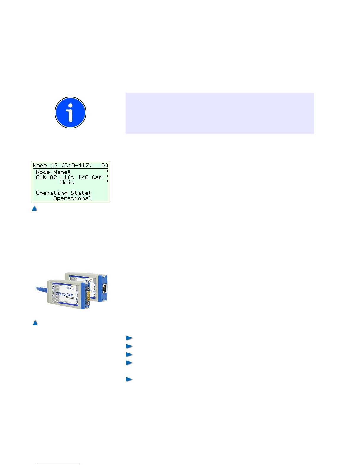
8.6.2 Checking the Bus Termination
As mentioned in section 7.9 "Installation of the Bus", the bus must be
terminated at both ends. Check both car bus and group bus to make
sure that they have properly terminated ends.
INFO!
Some types of position systems always terminate the can bus. In
such case, the termination on the CLK-03 has to be deactivated with
the DIP switch. You can find information on terminating devices in
their accompanying manuals or online at www.CANopen-Lift.org
8.6.3 Checking the CAN Parameters
To check the CAN parameters of the control unit, call up the setup
information or the setup menu of the control unit. In PARAMETERS
→ TERMINALS → TERMINALS CAN1/2 you can find a list of all connected CAN devices. Check if the devices that are to be used in your
system have been activated
.
As all CAN devices are pre-configured upon delivery of the control
unit, you need not set further parameters at this point. If you combine
a control system from OEM components, you may optionally purchase a USB CAN adapter for the PC and CANwizard®« software for
parametrising the CAN devices. You can, however, also configure the
input and output terminals on the control display. Learn more about
CANwizard® and the configuration of devices in the CANwizard
manual and at www.CANwizard.de.
If all devices have given correct feedback, you can start the first
travel with emergency controls.
8.6.4 Checking the DCP Connection
If the inverter is selected via a DCP interface, the following items are
to be checked:
Does the wiring comply with the circuit diagrams,
Has bp308 been set to the correct drive/inverter type,
Has the DCP interface been activated in bp308 and in the inverter,
Have both units (control and drive) been set to the same protocol
(DCP3/DCP4+),
Are there no malfunctions at present.
90 Installation Manual System »bp308« – Commissioning Instructions
Fig. 56
A CLK unit correctly booted up
connected at the CAN-bus.
Fig. 57
Example of a IXXAT USB to
CAN adapter used for configuring CAN components.
Page 89
8.7 First Travel with Emergency Controls
The emergency control is used for moving the lift during installation
and maintenance work.
CAUTION!
Pay attention to the safety instructions in section 2.2 "Safety Information“. For your personal safety it is important that the switches of
emergency control, inspection control and emergency stop as well as
buttons up and down have been wired into the safety circuit as stipulated in the wiring diagram.
Emergency stop, door and locking contacts must not be bridged!
This ensures that any interruption of a contact, either emergency,
door or lock, immediately stops the lift.
If the emergency control switch is on, the terminals X5.15 and
X12.102 must be dead and terminal X7.101 live.
Correction switches S71 and S72 must be fitted at the right deceleration point at the terminal landing and switch reliably.
If either switch up or switch down of the emergency control is activated, the contacts of the safety circuit must either be closed or
bridged by the switch of the lift control.
Travel commands are controlled and monitored by the control system bp308.
If a photocell is integrated, terminal X7.53 (door B: X7.56) must be
live.
The command key (emergency control switch) is located in the
door of the control cabinet in the machine room (see DIN EN 81, part
1, 14.2.1.4).
INFO!
During the first travel with emergency controls, check under DIAGNOSTICS > SIGNALS > WELL SIGNALS if the indicated speed
corresponds with the speed shown on the inverter. If both speeds
mismatch, check the conversion factors of both systems.
INFO!
If the inspection control unit is switched on, it overrides the emergency control unit (see DIN EN 81, part 1, 14.2.1.3 and 14.2.1.4).
If the control unit is made by BÖHNKE + PARTNER GmbH, prefer ence is also given to the inspection control when the car or door can-
91
Page 90

not be moved any more, with the inspection control turned on and the
emergency control switched in and vice versa.
The emergency control functions are essentially the same as those
of the inspection control, but the following safety devices are bridged:
Speed governor,
Buffer contacts,
Emergency limit switches,
Safety gear contact, and
Minimum pressure switch of hydraulically operated lifts.
The car can be driven from the limit switches, if the inspection control
is switched off and the emergency control switched on.
Switching the emergency control deletes all existing calls and disables the push buttons for cabin calls, landing calls and superior control functions.
If the control unit is not equipped with an absolute encoder, a correction travel is required as soon as you have returned to normal
operation. Enter a call for that purpose.
8.8 First Travel with Inspection Controls
The inspection control is used for moving the lift during installation
and maintenance work.
CAUTION!
Pay attention to the safety instructions in section 2 2.
For your personal safety it is important that the switches of emergency control, inspection control and emergency stop as well as buttons up and down have been wired into the safety circuit as stipulated
in the wiring diagram.
Emergency stop, door and locking contacts must not be bridged!
This ensures that any interruption of a contact, either emergency,
door or lock, immediately stops the lift.
If the inspection control switch is on, the terminals X5.15, X7.101 and
X12.102 must be dead.
Correction switches S71 and S72 must be fitted at the right deceleration point at the terminal landing and switch reliably.
If either switch »Up« or switch »Down« of the inspection control is
activated, the contacts of the safety circuit must be closed.
Travel commands are controlled and monitored by the control system bp308. All safety circuit devices remain operational. If any of the
contacts in the safety circuit are interrupted, the lift is shut down
immediately. If a photocell is integrated, terminal X7.53 (door B:
X7.56) must be live.
The inspection control is situated on the roof of the car. Switching
the inspection control on disables automatic door functions and also
92 Installation Manual System »bp308« – Commissioning Instructions
Page 91

automatic lift operation. Moving the car and the door is only possible
by activating the command buttons of the inspection control unit
(dead man's circuit) in absence of the emergency control functions
(either switched off or not installed). In addition, activation of a stop
button, which can only be returned to its original position by turning it,
can cause an emergency stop. The limit switches prevent the car
from over-travelling the terminal landings.
INFO!
Switching on the inspection control overrides the emergency control
(see DIN EN 81, part 1 , 14.2.1.3 and 14.2.1.4)
If the control unit is made by BÖHNKE + PARTNER GmbH, prefer ence is also given to the inspection control when the car or door cannot be moved any more, with the inspection control turned on and the
emergency control switched in and vice versa.
Switching the inspection control deletes all existing calls and disables
the push buttons for cabin calls, landing calls and superior control
functions.
All safety circuit devices remain effective (DIN EN 81 part 1,
14.2.1.3).
Once the lift system is switched back to normal operation, you can
make a call to trigger correction travel for the landing counter. Control
units equipped with an absolute encoder do not require a correction
travel.
93
Page 92
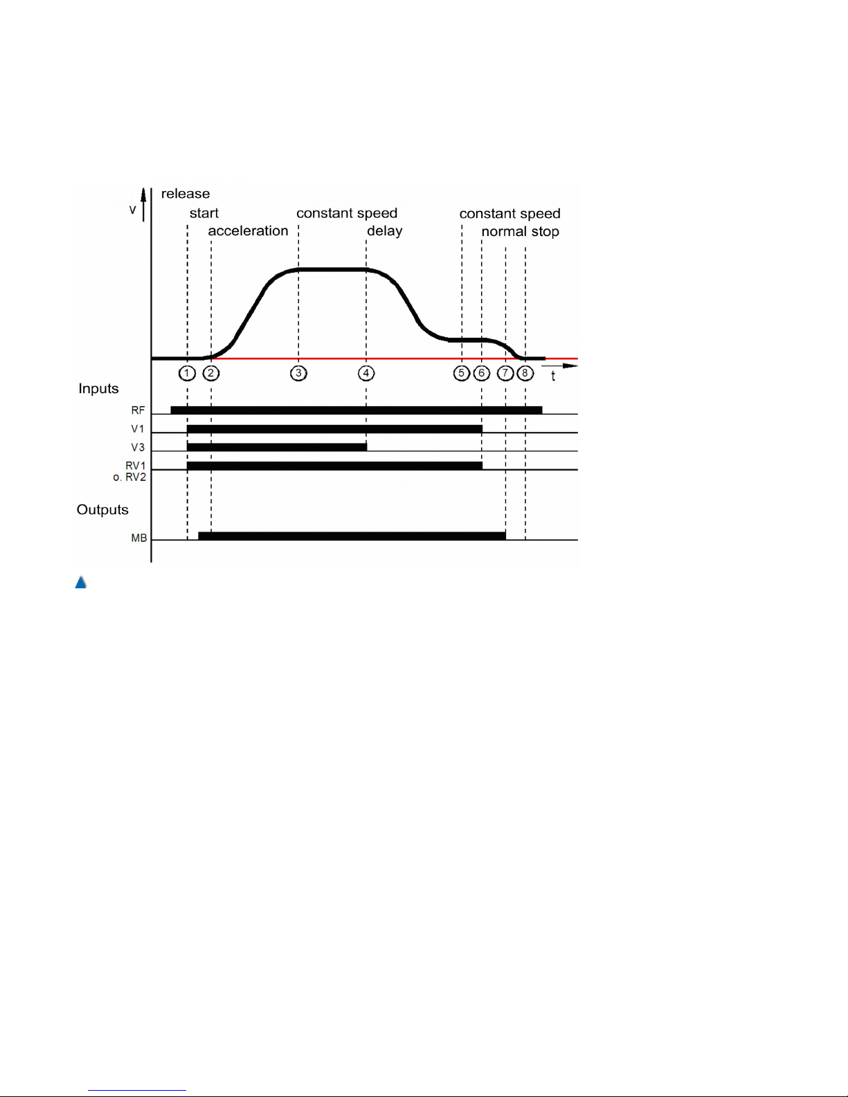
8.9 Course of a Regulated Two Speed Travel
(Summary)
After switching on the main contactor and releasing the inverter, the
control unit selects the inverter by setting the direction of travel,
speed V3 and the starting signal. The inverter keeps the motor at
idling speed of n=0 revolutions per minute and sends signal MB to
the control unit (1 to 2) via terminal 31, which opens the electromagnetic brake. After switching on the brake via relay K4 of the control
unit, the motor accelerates until speed V3 is reached (2 to 3). A travel
at constant speed follows (3 to 4) until speed V3=0 is cancelled. The
motor slows down to positioning speed V1 (4 to 5). After a short distance, speed V1=0 is no longer selected (5 to 6), and the motor
decelerates further (6 to 7). As soon as the motor stands still, the
inverter closes the electro-magnetic brake MB (7 to 8). The main contactors are switched off with a time delay through the RF signal.
94 Installation Manual System »bp308« – Commissioning Instructions
Fig. 58
RVM-01controls the inverter during normal travel.
Page 93
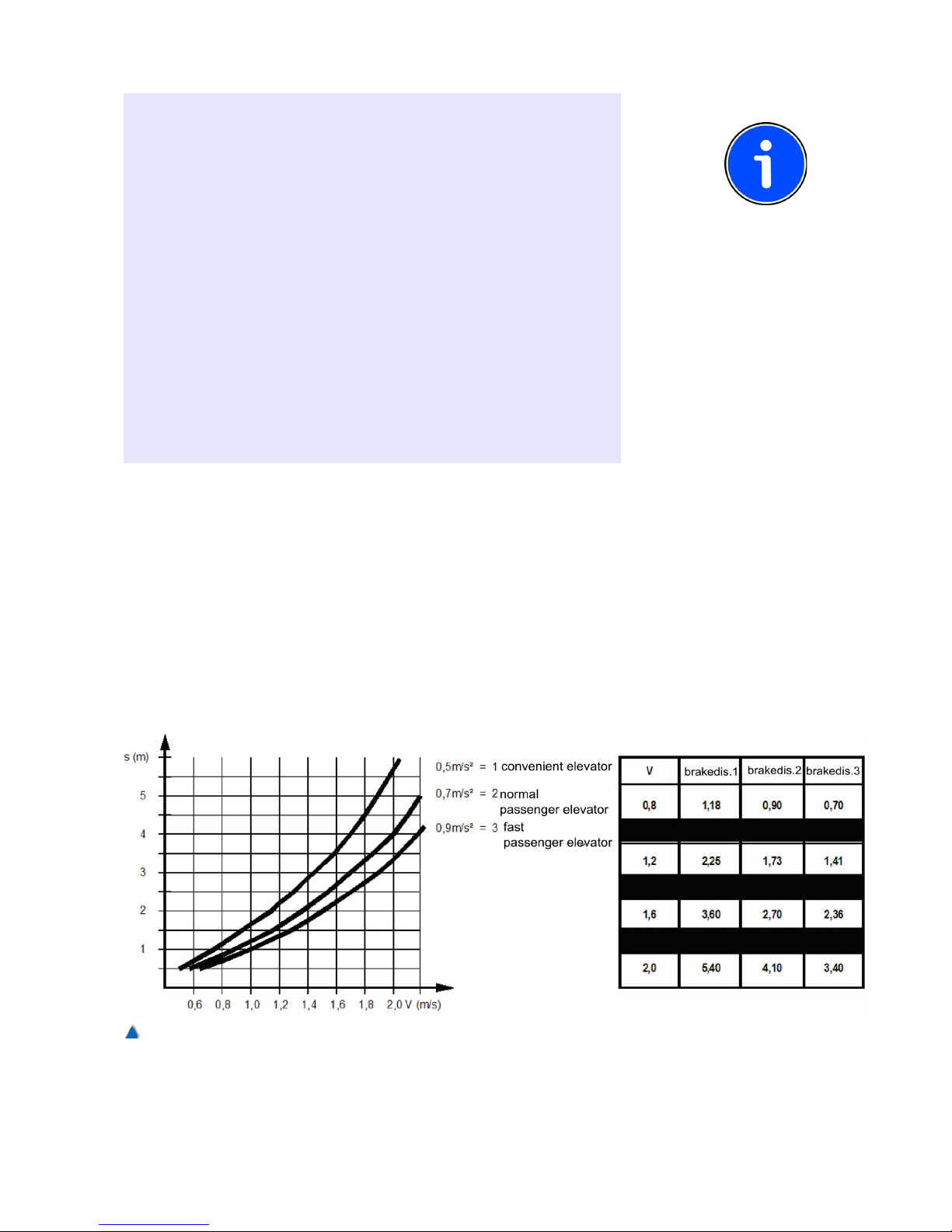
INFO!
• The electromagnetic blocking brake must be switched on and off
without time delay through relay MB, in order to ensure that the
inverter initiates smooth starts and stops.
• The main contactors to the motor must be switched on and off
without time delay through relay RB to ensure smooth starts and
stops .
• If the collective malfunction relay of the inverter becomes dislodged
due to a malfunction, the control unit must ensure that the mechanical brake and main contactor to the motor are switched off immediately. The output of the collective malfunction relay of the inverter
is connected to terminal 34 of the control unit.
• Together with the mains contactor of the inverter, the mains contactor of the control unit has to be opened or closed without time
delay. This is the only way to monitor the brake chopper with
regard to excess temperature and disconnect the inverter from the
mains, if necessary.
8.9.1 Disconnection Points for the High Travelling
Speed (V3)
The deceleration distance can be taken from the diagram. The values
shown are only valid if the factory set rounding R_NEG1=60% and
R_NEG2=90% are not changed. Moreover, it is assumed that the
control unit gives the disconnection points to the inverter without
delay.
The values shown are benchmark values only and should be adap-
ted to your individual requirements on site.
95
Fig. 59
Diagram and table of deceleration distance
Page 94
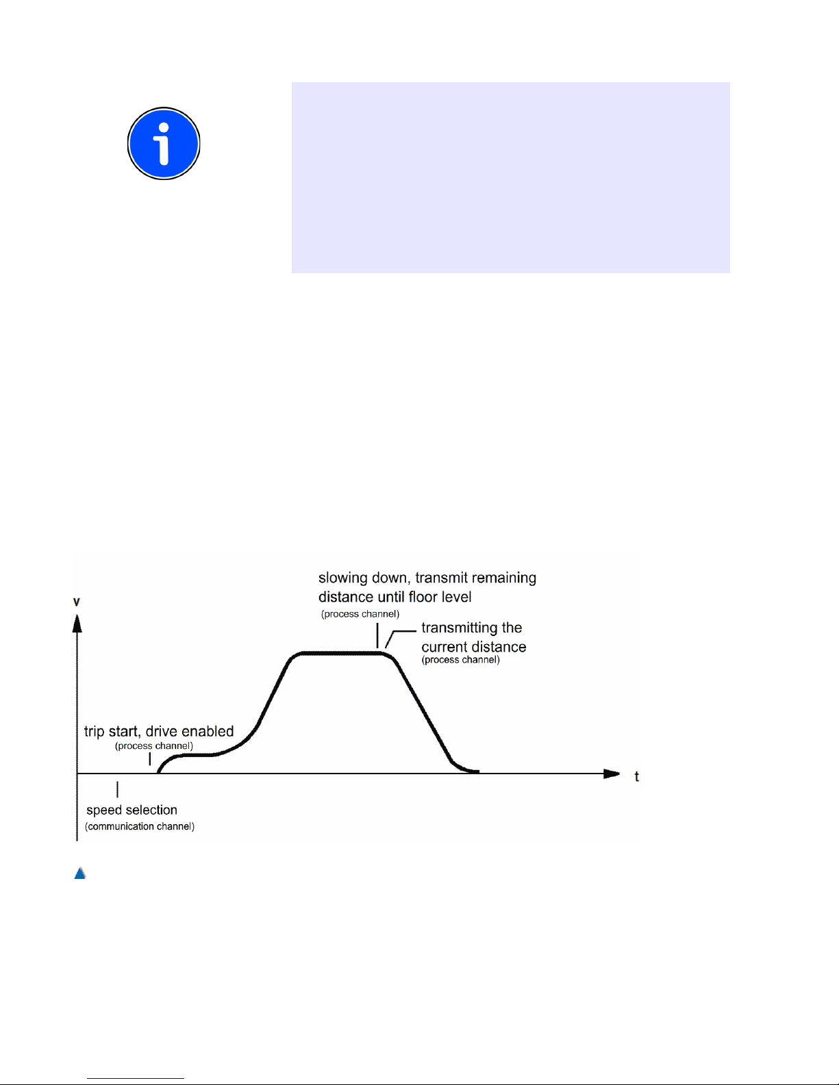
RECOMMENDATION
The disconnection point should − if possible − be set to a value
higher than the determined deceleration distance in order to create
leeway for the optimisation of the speed curve behaviour. .
To achieve distances travelled at speed V0 that are as equal and
short as possible, the disconnection points must be set with an accuracy of +/-1 cm.
The disconnection points for speed V2 must be set with an accuracy
of +/-1 mm, depending on the setting of V0 before reaching the flush
landing level.
8.10 Course of a Direct Travel with DCP (Sum-
mary)
With protocols DCP3, the control unit and the inverter serially
exchange only signals that would travel via terminals in case of selection. The speed curve corresponds to a normal travel as described in
the previous section.
At the protocols DCP4 or CANopen, the control unit cyclically
transmits, besides some control signals, the remaining distance to
the next landing to the inverter, thus enabling the inverter to calculate
an ideal speed curve and make the car approach the landing directly.
96 Installation Manual System »bp308« – Commissioning Instructions
Fig. 60
Speed curve of a travel with direct landing approach
Page 95
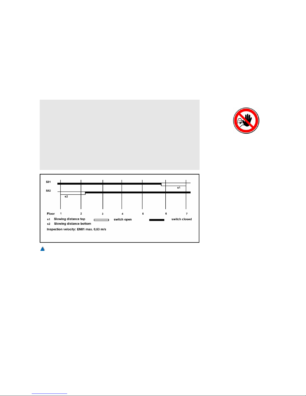
8.11 Commissioning of the Floor selector System
As soon as it possible to travel with inspection control, the transmitters of the Floor selector system can be mounted and installed. It can
be either magnet switches, absolute rotary shaft encoders (AWG-05)
or linear encoder systems such as USP or laser positioning systems.
8.11.1 Installation of the Deceleration Switches
ATTENTION!
For your personal safety, make sure that the inspection switch ONOFF as well as the buttons UP-DOWN and EMERGENCY STOP
have been wired into the safety circuit according to the circuit diagram.
To decelerate the first travels even when the absolute encoder has
not yet been installed, first install the deceleration switches S81 and
S82 for inspection and emergency control at the terminal landings
putting them at their correct deceleration points in the well, and
ascertain that they switch properly.
Deceleration is initiated when the switches in the direction of travel
open accordingly. Deceleration switch S81 opens and starts deceleration for the top landing. Deceleration switch S82 opens and starts
deceleration for the bottom landing. The deceleration of inspection
and emergency travels has to be carried out at these deceleration
points as well. The flush-level position of the terminal landings must
not be over-travelled.
Please set the following in the service menu:
> MAINTENANCE
97
Fig. 61
Pulse diagram of the deceleration switches
Page 96
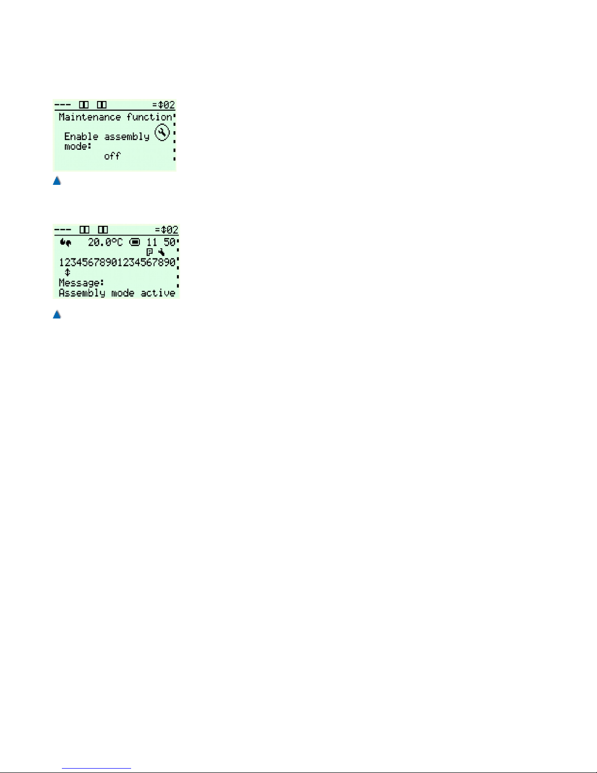
> MAINTENANCE FUNCTIONS
Scroll through this sub-menu until you reach ENABLE ASSEMBLY
MODE and select ON. Now scroll further to ASSEMBLY MODE
WITH PRE-LIMIT SWITCHES (S81/S82) and select ON.
After that you can start travelling with inspection/emergency control in
order to install the Floor selector system as described in section 6.6.
8.11.2 Basic Settings
After installing the CAN transmitter system (see installation manual
enclosed), select the following presets in the bp308 setup menu:
Setup menu: > PARAMETER
> LIFT DATA
> FLOOR SELECTOR > ABSOLUTE ENCODER (CAN)
followed by: > PARAMETER
> FLOOR SELECTOR
> APS1 PARAMETER
TYPE
CODE SEQUENCE
Deceleration points and flush-level positions can comfortably be set
via special setting menus.
In the service menu, the following basic settings have to be selected:
Service menu: > SETTINGS
> FUNCTIONS
> DRIVE UNIT
> TRAVELLING SPEED
> DECLARATION DISTANCE
> MINIMUM TRAVEL DISTANCES
Enter the nominal and intermediate speeds of the system.
Go to this menu : > SETTINGS
> SHAFT ENCODING
> PARAMETER
> GENERAL WAYS
SHAFT PIT
SHAFT HEAD
CAR HEIGHT
Enter an approximate depth of the shaft pit, i.e. the distance between
the sill of the bottom landing and the floor of the shaft pit.
This value has been preset to 1 m at factory and is meant to obtain
the most precise well representation possible.
98 Installation Manual System »bp308« – Commissioning Instructions
Fig. 62
Activating the assembly travel
to move the car without encoder
system.
Fig. 63
Information on the activated
assembly travel in the standard
view.
Page 97
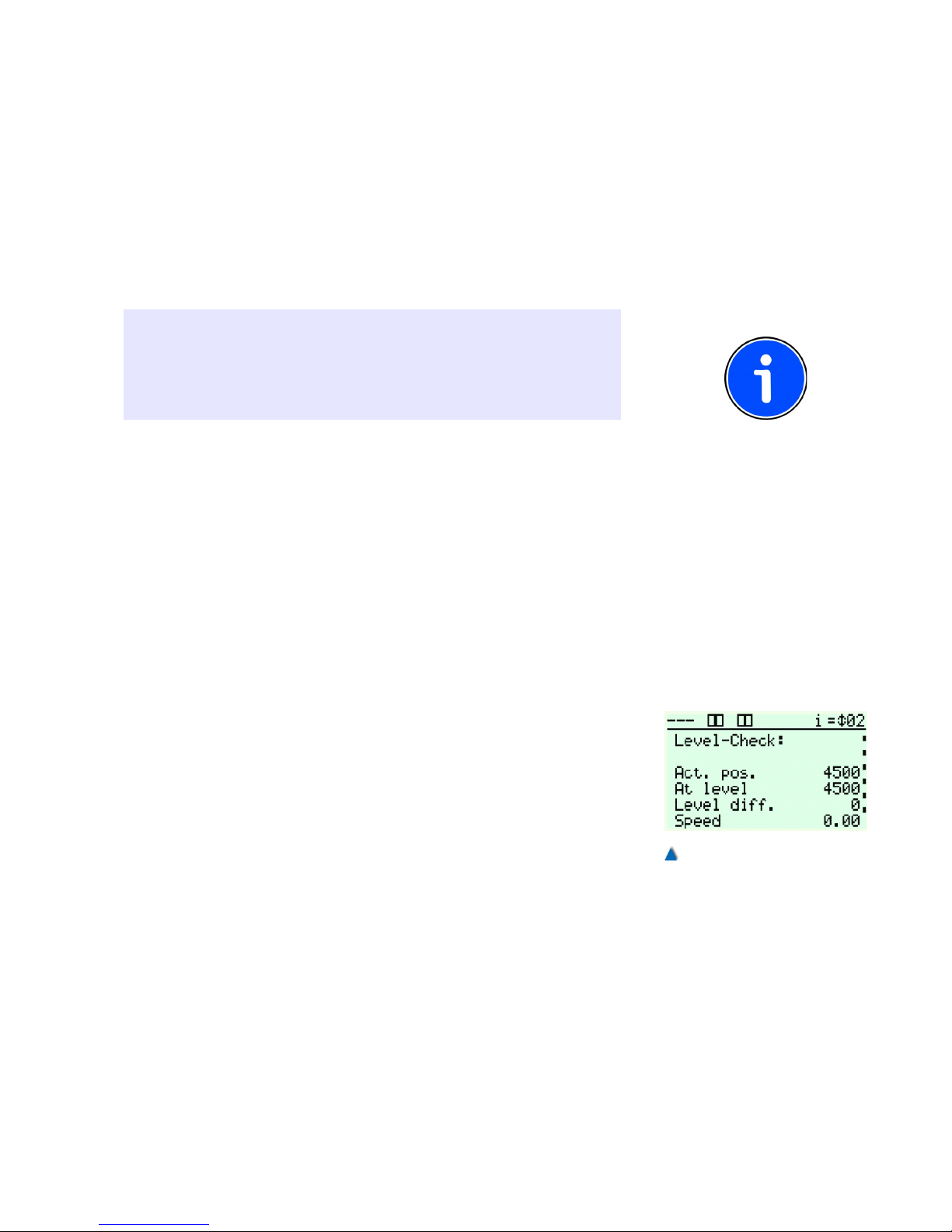
8.11.3 Read-in Travel with Absolute Encoder
After completing all these settings, you can initiate the read-in travel
in compliance with the following instructions. During the read-in
travel, the flush-level positions of every landing are precisely determined and memorised in the program memory. From the data gathered
by the read-in travel combined with the parameters set, the control
program calculates the virtual floor selector.
INFO!
It is recommended that two persons carry out the read-in travel
together. It is of utmost importance that the flush-level positions are
approached and read-in with perfect precision as the control system
calculates the landing parameters from the values read in.
Please proceed as follows:
1. Switch the lift to the INSPECTION operation mode.
2. Activate the ABSOLUTE ENCODING menu and then READ-IN
TRAVEL (It is possible to leave the program by pressing the
Call/End button at any time).
3. Move the lift to the bottom landing (landing 1) as near as possible
to the flush-level position with the inspection button. For a rope
traction lift, you reach this precise position by releasing the brakes
and turning the hand wheel.
4. For a hydraulically operated lift, approach the precise flush-level
position of the bottom landing by operating the emergency valve
or the hand pump.
5. After positioning the lift flush with landing level 1, activate either
the OK button of the LC display or the cabin call button of landing
1. Button 1 lights up to acknowledge the correct reading-in of the
flush-level position.
6. Repeat this procedure for every other landing as well.
7. After reading in every flush-landing level position, you can switch
the lift back to normal operation mode.
Move the lift to every landing from both directions and check whether
the car stops at the flush-landing levels. To do this, use the level control under DIAGNOSTICS > SHAFT SIGNALS > LEVEL CONTROL.
If the lift does not stop at the previously memorised position, you can
adjust the DECELERATION DISTANCE V0 (STOPPING DISTANCE)
under FUNCTIONS > DRIVE UNIT.
The range of the re-levelling area can be adjusted independently
from the flush-level area. Refer also to the service menu TIMES >
DRIVE UNIT / RELEVELLING DELAY TIME.
99
Fig. 64
Level check dialog
Page 98
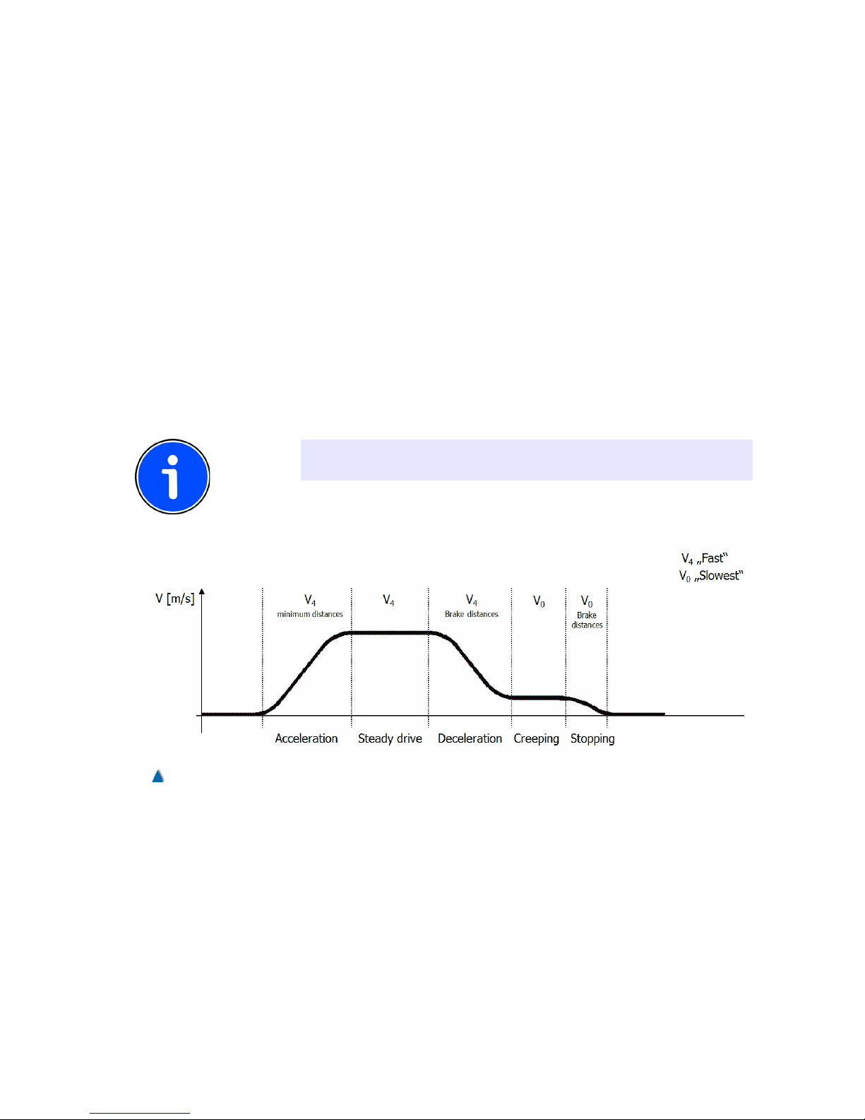
8.11.4 Travel Speeds
Travel speeds are set in the service menu under SETTINGS >
FUNCTIONS → DRIVE UNIT. Abbreviations of different speed designations:
VN = Re-levelling speed
VI = Inspection speed
VR = Emergency speed
V0 = Levelling speed
V1..V7 Intermediate and fast speeds, depending on the selected
drive type.
The braking and minimum distances can be re-calculated when changing the travel speed. These have to be adjusted, if necessary.
INFO!
V0 < V1 < V2 < V3 < V4 < V5 < V6 < V7!
100 Installation Manual System »bp308« – Commissioning Instructions
Fig. 65
Example of a speed curve when a DCP-03 connection with V4 nominal speed is selected.
Page 99

INFO!
For speed controlled lifts, you have to adhere to the instructions of
the frequency inverter manufacturer!
Deceleration distance V1..7 = Deceleration sets in toward the
landing Deceleration distance VI = Deceleration sets in during
Deceleration sets in during VR = Deceleration sets in with emergency control (if supported separately by the drive unit)
Deceleration distance V0 (stopping distance) = Disconnection point
Re-levelling flush down = Re-levelling to flush landing level
Re-levelling flush up = Re-levelling to flush landing level
Landing area down = Level control when car stops
Landing area up = Level control when car stops
Zone area down = Switching threshold for door starting to
open while car is slowing down to
approach the landing
Zone area up = Switching threshold for door starting to
open while car is slowing down to
approach the landing
• shaft pit (limit down travel)
Standard is set to 1 m. It can be adapted to the actual value in
order to calibrate the well with effective values. It also defines the
operating range of the transmitter.
• Shaft head (limit up travel)
Standard is set to 1.5 m. It can be adapted to the actual value in
order to calibrate the well with effective values. It also defines the
operating range of the transmitter.
• Car position
This value is required for travelling to the maintenance position. It
should be selected so that the field engineer can easily access the
car roof.
8.11.5 Deceleration through S81/S82 with Normal
Operation at the Terminal Landings
Some operators request an additional safety device for the top and
bottom landings. It ensures that the lift is switched to the levelling
speed (V0) before reaching the terminal landing. This option is
provided by operating the deceleration switches S81 and S82.
101
Page 100
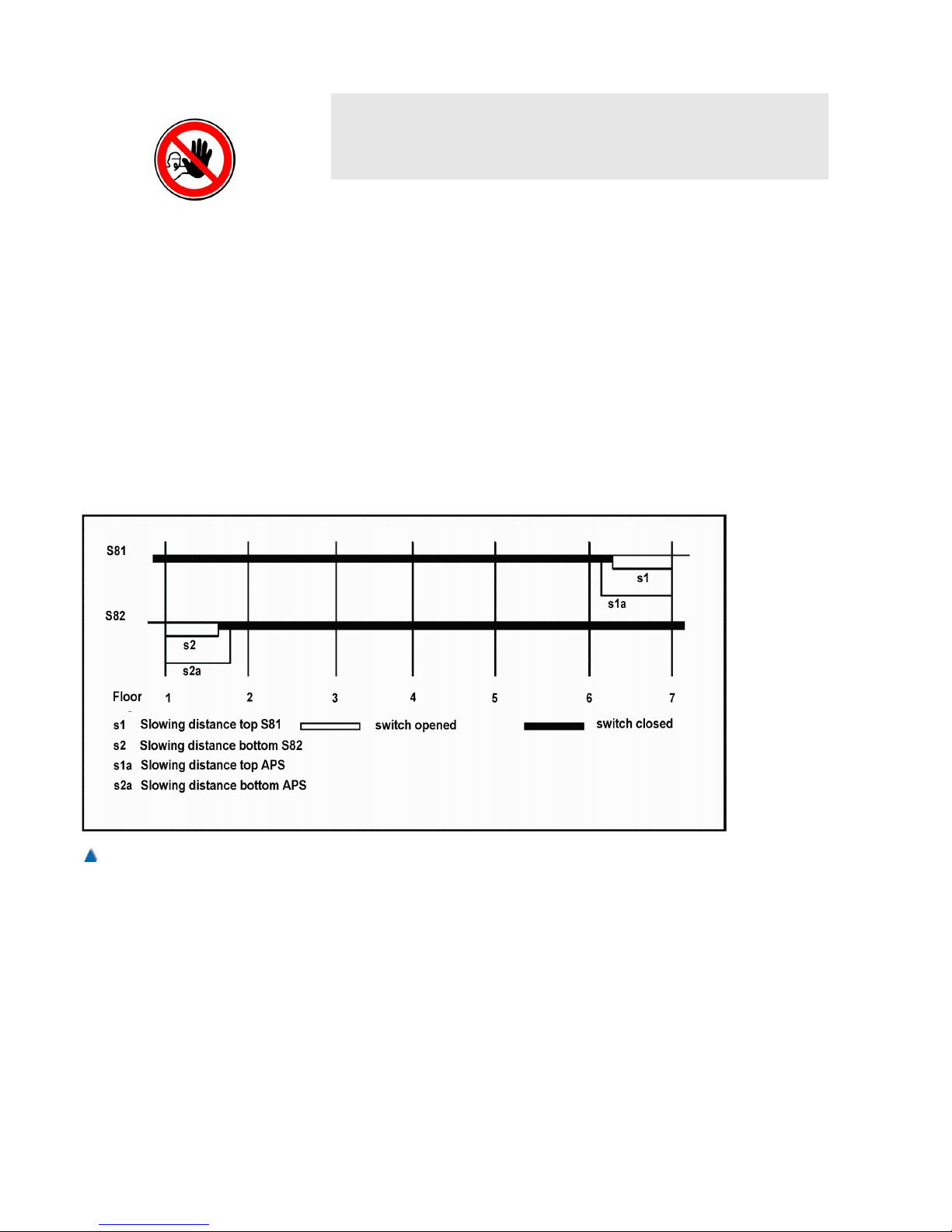
CAUTION!
It is essential for this application that the deceleration switches S81
and S82 are mounted at the proper deceleration points and function
perfectly.
Deceleration of a travel at maximum speed must set on at these
deceleration points and the flush-level position of the terminal landings must not be over-travelled.
Deceleration is initiated when the switches in the direction of travel
open accordingly.
Deceleration switch S81 is related to upward travel and opens to
switch the lift to low speed (V0) before reaching the top landing.
Deceleration switch S82 is related to downward travel and opens to
switch the lift to low speed (V0) before reaching the bottom landing.
Settings in the setup menu: > FUNCTIONS
> FLOOR SELECTOR
> DECELERATION (S81/82)
ON
102 Installation Manual System »bp308« – Commissioning Instructions
Fig. 66
Pulse diagram with magnet switches and AWG-05
 Loading...