

Page 1

Operating Instructions
Böhmer Fully Welded Ball Valves - Type BBF
Rev.: 06/2013
Authorized Distributor:
Liberty Sales and Distribution, LLC
2880 Bergey Road, Suite F
Hatfield, PA 19440
Phone: (877) 373-0118
Fax: (888) 850-3787
Email: [email protected]
1
Page 2

TABLE OF CONTENTS PAGE
1. Safety instructions 3
1.1 Use in accordance with the intended purpose 3
1.2 Action in the case of malfunctions 4
2. Acceptance and transport 5
2.1 State as delivered 5
2.2 Checking of the delivery 5
2.3 Storage 5
2.4 Transport 5
3. Fitting and commissioning 6
3.1 Mounting position 6
3.2 Welding 7
3.3 Water pressure test 7
4. Operating and test for tightness 9
4.1 Opening and shutting off 9
4.2 Proof of tightness under operating conditions 9
4.2.1 Ball valves without test connection 9
4.2.2 Ball valves with test connection 9
5. Maintenance / repairs 11
5.1 Leaks on the actuation journals 11
5.1.1 Ball valves without test connection 11
5.1.2 Ball valves with test connection 12
5.2 Variants 13
• Variant 1 13
• Variant 2 14
• Variant 3 15
6. Accessories 16
6.1 Injecting of sealing agent 16
2
Page 3
1. SAFETY INSTRUCTIONS
1.1 Use in accordance with the intended purpose
The fully welded type BBF ball valve is designed exclusively for opening pipes fully
for the flow of materials or for shutting them completely. Every other form of use, e.g.
for regulating flows, counts as not being in accordance with the intended purpose.
Use in accordance with the intended purpose also includes the observation of the
instructions in these operating instructions, the maintaining of the operating
conditions as stated on the type plate, acceptance certificates and drawings as well
as the observation of the relevant accident prevention and environmental protection
regulations applying at the place of use.
These operating instructions are intended for the expert personnel of the operator of
the ball valve.
The safety instructions are to be read before the ball valve is transported, fitted or
repaired and are to be kept safely.
In these operating instructions the safety instructions are high-lighted clearly from the
remaining text. There are two different types of safety instruction:
IMPORTANT
Signifies a situation that could be dangerous and gives hints on how
damage can be avoided.
DANGER
Indicates the direct risk of danger for health and life and limb or the risk
of serious material damage, in each case in the event of the instructions
not being observed.
3
Page 4

1.2 Action in the case of malfunctions
The following safety instructions are to be observed.
Repairs to the ball valve, which become necessary in the course of the normal
operation of the ball valve, may be carried out but only after the permission thereto
has been obtained from Böhmer GmbH for each individual case.
All other repairs, e.g. that become necessary following damage through force
majeure or through causes which do not lie in the field of normal operation of the ball
valve, are to be carried out solely by Böhmer GmbH.
In the case of repairs to be carried out by the ball valve operator's, the following
manufacturer's instructions are to be observed:
- The statement of position of Böhmer GmbH is to be obtained before the repair is
carried out.
- Photos are to be taken before and after each repair.
- Repairs are to be carried out only using spare parts from and in accordance with
the fitting instructions of Böhmer GmbH.
- A report is to be prepared with the following statements:
• Cause of damage, effect of damage
• Spare parts, special tools and fitting devices used
• Repair measures and tests carried out
• Names of the persons carrying out the repairs, of the person responsible
therefor and the date on which the repairs were carried out
• Photos
4
Page 5
2. ACCEPTANCE AND TRANSPORT
2.1 State as delivered
The ball valves are provided with a coating and type plate in accordance with the
particular order and - in so far as the order does not contain something different - are
supplied in the following form:
• The ends on to which welding is to be carried out and the flange connection
sides are provided with an anti-corrosion agent.
• Connection openings are closed with PE protective caps or wood lids to
prevent dirt and moisture getting in.
• The ball valves are packed on wooden pallets or in skeleton containers.
2.2 Checking of the delivery
Check the delivery without delay following receipt for transport damage. In the case
of damage observe the instructions of the insurance companies which - amongst
other things - will prescribe an immediate recording of the state of affairs by the
forwarding agent. Wherever possible document damage with photos.
In addition check the delivery for completeness against the delivery notes. Inform
Böhmer GmbH without delay if anything is missing.
2.3 Storage
• Leave the ball valves in the transport devices and in the packing material.
• Protect the ball valves against dirt if necessary. Cover them with plastic film.
Ball valves have to be stored in dry conditions and under cover.
• Do not actuate the ball valves while they are being stored.
2.4 Transport
IMPORTANT
Transport each ball valve in such a way that you do not damage it
thereby. If using chains for lifting, place something suitable between the
ball valve and the chain to prevent damage to the external paintwork.
The paintwork has a protective function. Accordingly you must not allow
it to be damaged at any point.
DANGER
If the ball valve is delivered with the drive mounted on it, do not secure
the lifting devices (ropes, chains etc.) to the drive but only to the ball
valve itself. DANGER TO LIFE AND LIMB!
Secure the load in such a way that it cannot tip over to the side.
DANGER TO LIFE AND LIMB!
5
Page 6
3. FITTING AND COMMISSIONING
3.1 Mounting position
The ball valves are supplied in the open position. Fit them into the line in this state.
IMPORTANT
Do not put the ball valves into circuit until the pipes have been cleaned
since otherwise the balls and seating rings will be unnecessarily
subjected to or even damaged by dirt, rust and assembly residues.
In its standard version, the ball valve is designed for fitting in lines of pipes running
horizontally. In this situation the actuation shaft is aligned vertically upwards.
Other modes of fitting (e.g. pipe vertical, actuation shaft horizontal) are possible when
this is specified in the order.
The type BBF fully welded ball valves in sizes up to DN 100 (4“) can be fitted in all
fitting positions without approval having to be obtained therefor from Böhmer GmbH.
IMPORTANT
Consult Böhmer GmbH before planning a different fitting position for the
ball valves of sizes in excess of DN 100.
If it is necessary for the weight of the ball valve to be supported, the ball valve must
be provided with and stand on its own foundation or be supported separately in
another way whereby in each case it must be free to slide in its axial direction. Do
not use the ball valve as a fixing point for the line of pipes but support these
separately.
IMPORTANT
In the case of ball valves with a test connection, the inside of the
housing should be drained prior to commissioning prior to the periods in
which frost can be expected.
IMPORTANT
Before subjecting a ball valve to pressure, check that the test connection
is in the fully closed position if one is fitted.
6
Page 7
3.2 Welding
Depending on what is ordered, each ball valve has either two flange ends, one flange
end and one welding-on end, or two welding-on ends.
The welding-on ends and the flange connection sides of the ball valve are protected
with an anti-corrosion agent when supplied. Accordingly you must remove this
before welding on the welding-on end or connecting the flange.
IMPORTANT
Do not remove the protective caps until the ball valve is at the location at
which it is to be used and then only immediately before it is to be fitted!
The ball valve is to be fitted in its 100 % open position and should first of all NOT be
actuated. When welding the ball valve on, take care that the seals inside the ball
valve will not be heated to a temperature in excess of the permitted level of 140 °C.
In this connection the distances to the welding seam stated in the following table hold
good (if necessary the region between the welding seam and the seals must be
properly cooled).
Nominal width Distance to welding seam
1“ - 3“ 50 mm
4“ - 8“ 70 mm
10“ - 16“ 90 mm
> 16“ 150 mm
The above also holds good for all preheating work carried out as a preparatory stage
for welding.
3.3 Water pressure test
Only clean water of drinking water quality may be used as the pressure medium.
Carry out the measures in the sequence given below:
Prior to carrying out the water pressure test, clean the line of pipes and the ball
valves in order to completely remove all dirt, rust and assembly residues.
After filling the pipe with water, move the ball to the closed position and then open it
again a little (10-20 degrees). In this way you equalize the pressure on the sealing
rings and ball and protect these in this way from being overloaded by the test
pressure which will be well in excess of the nominal pressure.
7
Page 8

IMPORTANT
The test pressure may not be more than 1.5 times the nominal pressure
or, as the case may be, 1.5 times the permitted operating pressure.
Carry out the water pressure test.
After the water pressure test, move the ball to the fully open position again (or where
necessary to the fully closed position) and drain the line.
If there is a test connection on the ball valve, drain the inside of the housing of the
ball valve via this connection.
Actuate the ball valve once or twice with the test connection open. Then close the
test connection again.
If there is not a test connection, the ball valve should be actuated once or twice.
8
Page 9
4. OPERATING AND TEST FOR TIGHTNESS
4.1 Opening and shutting off
The open or closed position of the ball valve is defined by turning the actuation shaft
by 90 ° to its limit position, i.e. so that the delivery flow has the full cross-sectional
area open to it or so that the flow is completely shut off.
Note:
To ensure that the ball valve will have a long service life, pay attention to the fact that
the ball must always be moved to the fully OPEN or the fully CLOSED position and is
never left in an intermediate position in the operating mode.
Lines for measuring and monitoring purposes can be connected to the test
connection if there is one.
IMPORTANT
Keep to the operating conditions stated on the type plate.
4.2 Proof of tightness under operating conditions
Differentiation is made here between the following forms of execution:
4.2.1 Ball valves without test connection
With this form of execution a leakage test can only be carried out downstream of the
closed ball valve.
4.2.2 Ball valves with test connection
With this form of execution a leakage test can be carried out via the test connection.
IMPORTANT
The test pressure may not be more than 1.1 times the nominal pressure
or, as the case may be, 1.1 times the permitted operating pressure.
A tightness test must be carried out with the ball valve in its closed position. If this
has been agreed in the order, the tightness can also be checked when the ball valve
is open.
Open the test connection slowly to depressurize the inside of the housing - but do
this only when the ball is in its closed position. (If this has been agreed in the order,
the test can also be carried out when the ball valve is in its open position.) Danger of
injury!
9
Page 10
The general safety regulations applying at the place of installation are to be observed
in respect of the medium escaping into the atmosphere.
DANGER
There can be a DANGER TO LIFE depending on the medium!
Wait until the complete system has been depressurized and that no more medium is
escaping. After allowing a period for equilibrium to be reached, a check is then made
to see whether further medium is escaping. If there is, then the amount can be
measured by counting the number of drops or bubbles per minute.
If there is a leak at the spindle passage seal, then this can often be eliminated by
opening and closing the ball valve several times.
Then close the test connection again!
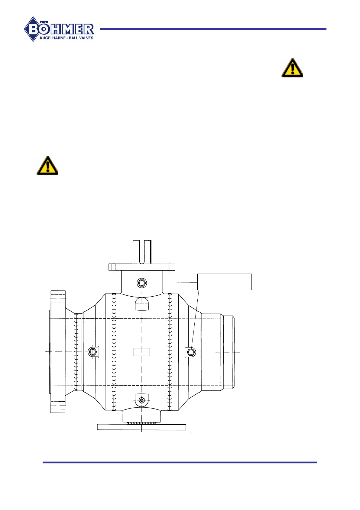
Option: Injecting in of sealing agent
When a system for injecting in sealing agent has been agreed in the order and if the
level of leakage cannot be accepted, a suitable sealing agent can be forced in via the
injection nipples until the leakage stops. An analogous procedure can be carried out
with the actuation journals (see Fig. 1).
For a description and the mode of procedure see section 6.
Fig. 1
Injection nipple
10
Page 11
5. MAINTENANCE / REPAIRS
Maintenance and repairs are only to be carried out on ball valves with nominal widths
in excess of DN 50 (2“). Böhmer GmbH is to be consulted in special cases.
IMPORTANT
You may only carry out repairs to the ball valve when you have received
special training from Böhmer GmbH in how to carry out these and when
permission to carry out the particular repair has been obtained from
Böhmer GmbH for each individual case.
All other repairs, e.g. in the case of damage through force majeure or
through causes which do not lie in the field of normal operation of the
ball valve, are to be carried out solely by Böhmer GmbH.
The ball valve is a fitting that requires no maintenance. The bearings on the
actuation journals and bearing pins (when present) are low-wearing, self-lubricating
PTFE products with excellent sliding properties. This fact means that the actuating
torque remains at a low and almost constant level even after a long period of
operation regardless of how often the ball valve is switched.
We recommend that each ball valve be put through at least one actuation cycle a
year in order to check that it is functioning reliably.
The repairs, which Böhmer GmbH permit the operator to carry out, can be executed
with the housing remaining in the line of pipes.
You may only carry out any repair during the warranty period after having obtained
the approval of Böhmer GmbH since otherwise the warranty obligation will be voided.
5.1 Leaks on the actuation journals
Differentiation is made between two basic types of fully welded ball valves:
5.1.1 Ball valves without test connection:
DANGER:
When there is a leak at the actuation journal with this form of execution,
the connected line of pipes must be depressurized before dismantling is
commenced. Otherwise it will be possible for the medium to escape in
an uncontrolled manner during dismantling causing injury and/or
material damage.
The dismantling steps for changing the actuation shaft seal are described under
Para. 5.2.
11
Page 12

5.1.2 Ball valves with test connection:
- When there is a leak with this form of execution, the inside of the housing of the
ball valve can be depressurized when the valve is in its closed position without the
connected line of pipes having to be depressurized. The inside of the housing
can also be depressurized when the ball valve is in its open position when this
has been agreed in the order.
DANGER:
With this form of execution, the inside of the housing must be
depressurized before dismantling is commenced. Otherwise it will be
possible for the medium to escape in an uncontrolled manner during
dismantling causing injury and/or material damage.
To carry out this depressurization, the shutting-off agent (ball) must be in its closed
position (also in the open position depending on the order and the particular form of
execution) and the inside of the housing must have been depressurized via the test
connection and rendered absolutely free of pressure. The test connection must
remain fully open until all assembly work has been completed.
Close the test connection again after all repair work has been completed!
The dismantling steps for changing the actuation shaft seal are described under
Para. 5.2.
12
Page 13
5.2 Variants
)
)
)
)
(5)
(5)
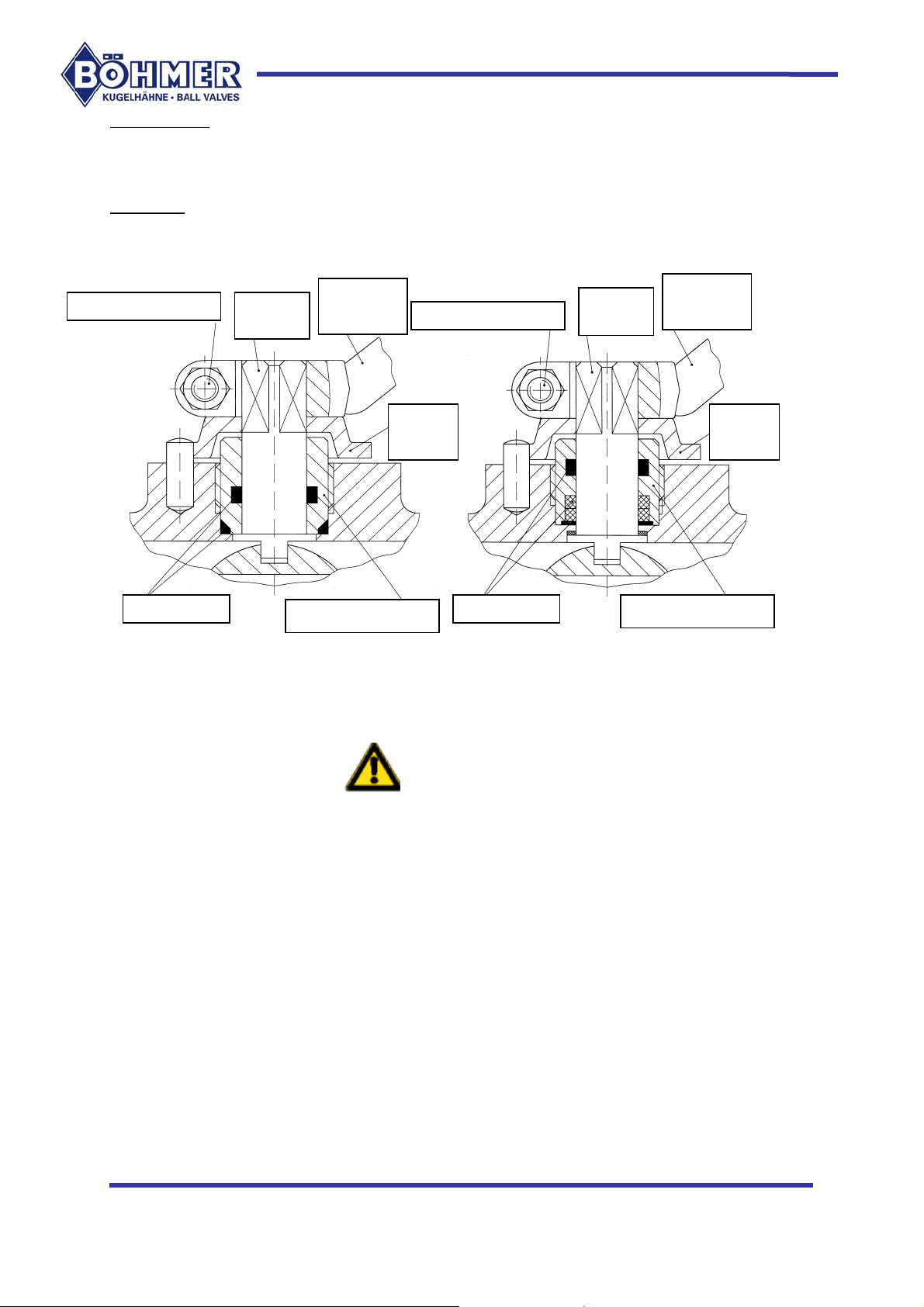
There are three different forms of execution of the spindle passage.
Variant 1
Medium is prevented from escaping through the spindle passage by two sealing
elements (see Fig. 2, Fig. 3).
Action
handle (1)
Locking screw (1.1
Spindle
Action
handle (1)
Locking screw (1.1
Spindle
Stop
bell (2)
Seals (4
Stop
bell (2)
Spindle union (3)
Seals (4
Spindle union (3)
Fig. 2 Fig. 3
The first measure to eliminate a leak at the spindle is to tighten up the spindle union
(3). If this does not cure the leak satisfactorily, the seals must be replaced.
IMPORTANT:
The further steps may only be carried out after it has been reliably
ascertained that the ball valve has been depressurized!
DANGER TO LIFE if the medium escapes!
Note: The work steps must be carried out precisely in the order given below.
1. Remove the actuation handle (1) by releasing locking screw (1.1); when a drive is
connected, mark the position and then disconnect the drive.
2. Remove the stop bell (2); this step does not arise if there is a drive.
3. Unscrew the spindle union (3).
4. Replace the seals (4).
5. Replace the spindle union (3).
6. Replace the stop bell (2) and the actuation handle (1) or, as the case may be,
drive.
7. Tighten up the locking screw (1.1) ); this step does not arise if there is a drive.
13
Page 14
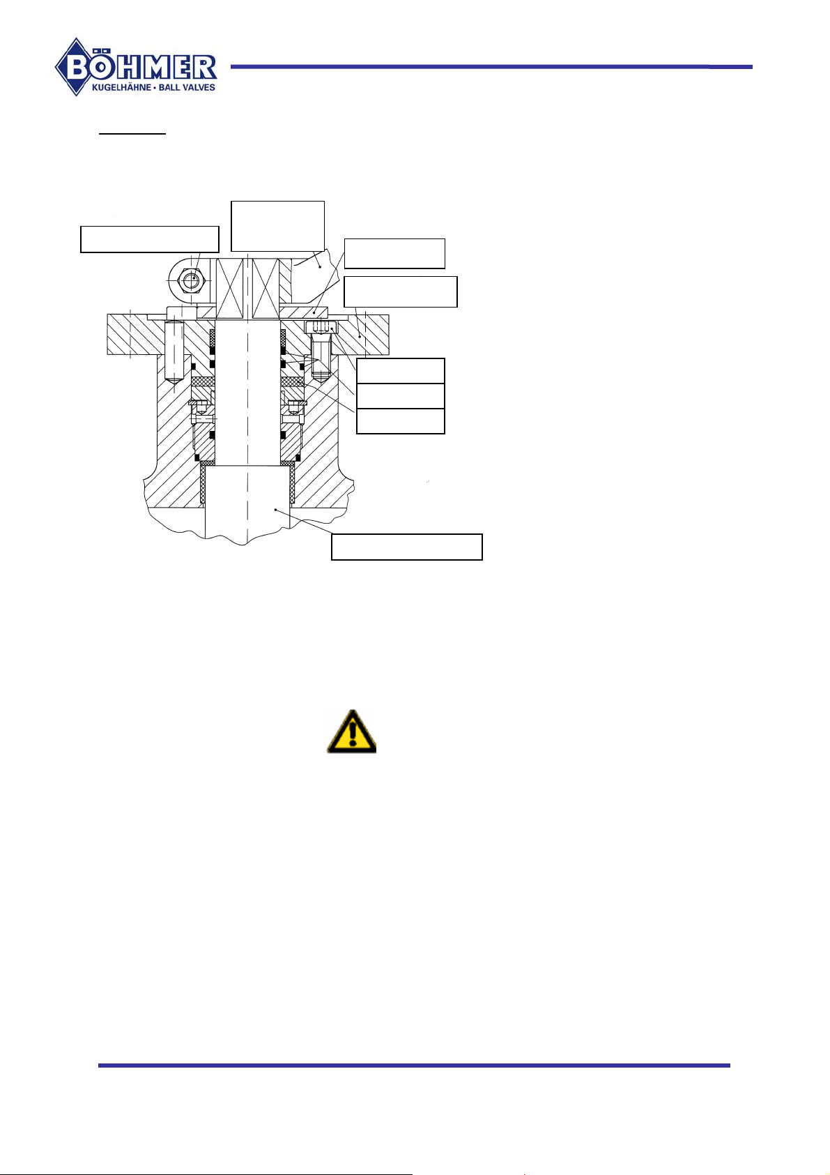
Variant 2
)
)
)
)
)
Medium is prevented from escaping through the spindle passage by four seals (three
O-rings and one flat seal). These seals can be replaced (see Fig. 4).
Actuation
Locking srew (1.1
handle (1)
Stop disk (2)
Flange plate (4)
Screws (3
Seals (7
Flat seal (5
Actuation spindle (6
Fig. 4
Option: Injection of sealing agent
If the ball valve has a sealing agent connection, the first measure that can be taken
to eliminate the leak is to force in a suitable sealing agent. The sealing agent fills up
every hollow space and stops the leak.
For a description and mode of procedure for this see section 6.
Should this measure not bring about a satisfactory result in the long-term, the seals
must be replaced.
IMPORTANT:
The further steps may only be carried out after it has been reliably
ascertained that the ball valve has been depressurized!
DANGER TO LIFE if the medium escapes!
Note: The work steps must be carried out precisely in the order given below.
1. Remove the actuation handle (1) by releasing locking screw (1.1); when a drive is
connected, mark the position and then disconnect the drive.
2. Remove the stop disk (2); this step does not arise if there is a drive.
3. The flange plate (4) can be removed after the screws (3) have been removed.
4. Remove the flat seal (5).
5. The actuation spindle (6) cannot be removed since with this variant it is secured
against being "blown out".
14
Page 15
6. Replace the seals (7) in the flange plate (4).
)
7. Fit a new flat seal (5).
8. Fit the flange plate (4), tightening up the screws (3) "crosswise".
9. Replace the stop disk (2) and the actuation handle (1) or, as the case may be,
drive.
10. Tighten up the locking screw (1.1); this step does not arise if there is a drive.
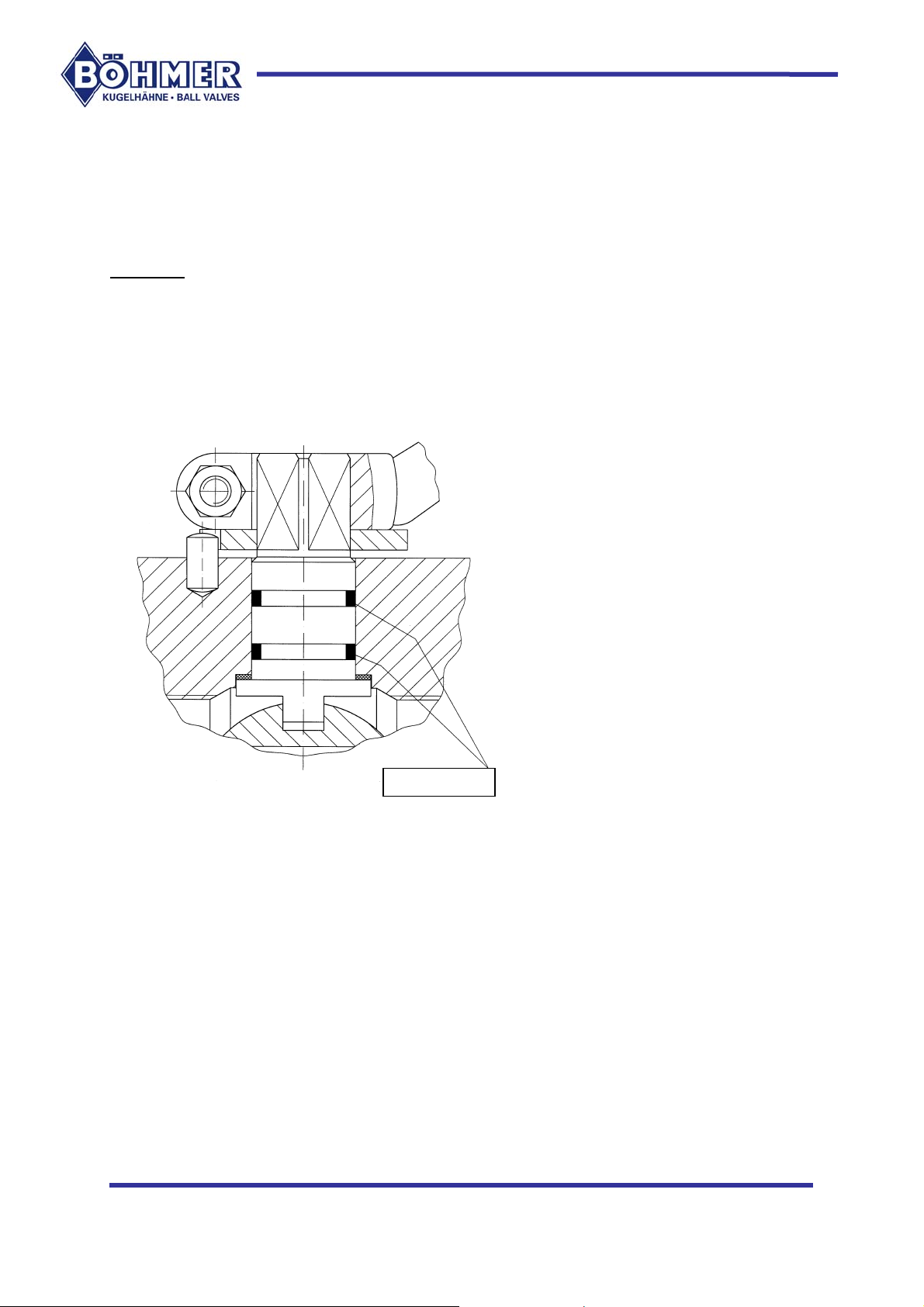
Variant 3
Here medium is prevented from escaping by two seals (1) (see Fig. 5).
With this version no adjustments can be carried out and the seals (1) cannot be
replaced. If leakage, occurs, the ball valve must be removed from the line of pipes.
Seals (1
15
Fig. 5
Page 16
6. ACCESSORIES
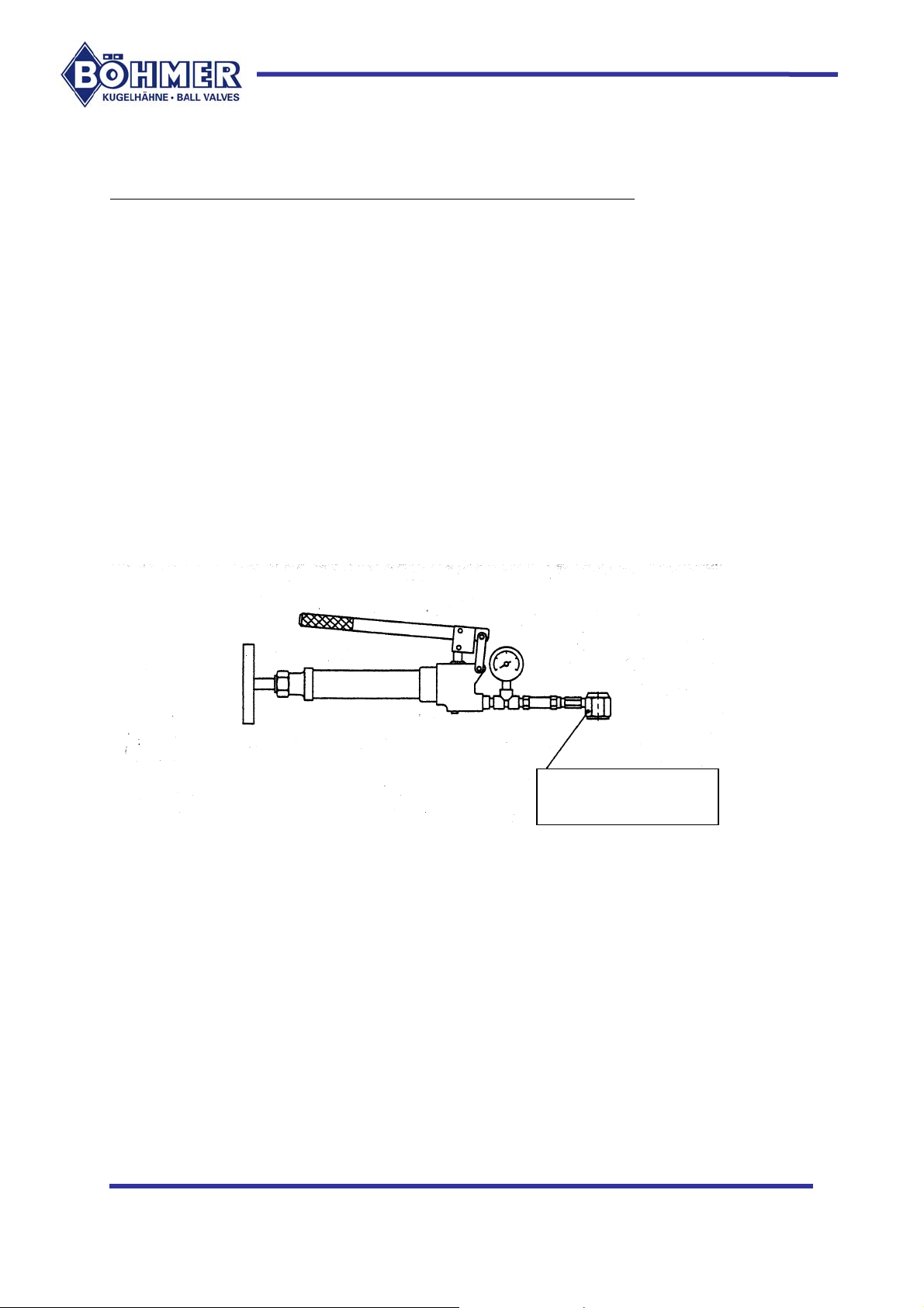
6.1 Injecting of sealing agent into the journal seal / seating rings
The transportable and easy-to-use sealing agent gun generates pressures of up to
100 Mpa. The sealing agent used is a highly viscous paste.
When it is necessary to inject sealing agent, a sealing agent cartridge is inserted in
the gun, the cap is removed from the injection nipple and the connection piece of the
gun is pushed over the injection nipple (see Fig. 6).
The sealing agent can now be forced into the ball valve by actuating the lever of the
gun.
When the pressure gauge on the gun shows an increase in pressure, this indicates
that the sealing agent channels in the ball valve are full.
Recommended sealing agent in so far as there are no particular prescriptions:
VAL-TEX No. 80, multi-purpose agent based on hydrocarbons, temperature range 29°C to + 260°C.
16
Connection piece to
Injection nipple
Fig. 6
Authorized Distributor:
Liberty Sales and Distribution, LLC
2880 Bergey Road, Suite F
Hatfield, PA 19440
Phone: (877) 373-0118
Fax: (888) 850-3787
Email: [email protected]
 Loading...