

Page 1

The Power Of Clarity
Owner’s Manual and Setup Procedures
RADIA Freestanding.................520i / 420i / 220i / 210i
Page 2

Introduction
Congratulations and thank you for selecting state of the art Radia Freestanding
loudspeakers from BG Corp. We have assembled your loudspeakers with the
greatest care and using the finest materials available. This craftsmanship,
combined with our patented planar ribbon technology, delivers sound
unmatched by any conventional loudspeaker.
Radia loudspeakers are ideal for either high performance stereo or home
theater applications. The flagship line from BG is comprised of the 520i Tower,
420i Tower, 220i Center Channel and 210i Active Subwoofer, all offered in
black anodized towers and black textured enclosures.
Models 520i, 420i and 220i feature our famous planar ribbon tweeters, along
with high performance cone woofers, that deliver the amazing clarity, imaging
and musicality that BG has become known for.
CONTENTS:
Page
Introduction and Table of Contents.....….............................2
Important Owner Information………………………..............3
General Information (Radia Series Unpacking)....…...........4
Setup for Optimum Performance ........................................5
Subwoofer Setup……………………………………...............9
Special Assembly Procedures.............................................12
2
© BG Corp 2005
Page 3

Important Owner Information
Read and Follow Instructions – Please read this entire manual before
unpacking and setting up your Radia Freestanding loudspeakers. For
maximum performance and years of trouble-free enjoyment, all operating
and care instructions should be followed.
Retain – DO NOT discard any factory packing material. The packing and
shipping materials may be required in the unlikely event your loudspeakers
need to be moved or shipped to our service center at BG.
Cleaning – Use a wax-free cleaning substance only (i.e. Pledge™) with
a soft, dry polishing cloth, not a paper-based chamois. DO NOT apply any
cleaning solutions to the grill cloth.
Liquid – DO NOT place BG loudspeakers near an open source of liquid
that may spill on the loudspeaker surfaces.
Heat – DO NOT place BG loudspeakers near a direct heat source.
Tipping – BG loudspeakers should be placed on a smooth flat surface
utilizing the enclosed spiked feet in order to ensure that the loudspeaker(s) do
not tip over. A loudspeaker tipping over can pose a hazard for small children
and pets.
© BG Corp 2005
3
Page 4

General Information
Unpacking Your BG Loudspeakers
1. Lay the shipping box down on the floor, ensuring that you have adequate space
to lay the loudspeaker down after removing it from the shipping box. Note: If your
floor is not carpeted, lay a blanket or other suitable soft fabric on the floor to prevent
damage to your loudspeakers.
2. Rotate the box so that the white product label affixed at the factory is on top and
facing up.
3. Pull the top flaps of the shipping box up, taking care not to cut yourself on the staples
used to close the box. Open the other cardboard flaps to expose the loudspeaker
still cradled in it’s protective foam and inside a protective plastic bag. Remove the
foam pieces over the top of the speaker. DO NOT open box ends.
4. Remove the loudspeaker by lifting it straight up and out of the box. Due to their
weight, we recommend that two people work together to remove Models 520i and
420i.
Assembly Instructions: Special assembly instructions can be found in the last
section of this manual.
Proper Hookup: Red terminal post to positive (+) amplifier post
Black terminal post to negative (-) amplifier post
Most BG loudspeakers can be bi-wired or bi-amped by simply removing the gold
plated jumper to allow separate wires to be run to the low and high pass section of
your system.
Break-In Times: Typically a BG loudspeaker requires not less than 48 hours of
operation at moderate sound level before reaching its optimum sound quality. This
improvement may be rather subtle but noticeable for a trained listener.
Note: Do not play your loudspeakers excessively loud to try to accelerate this
process!
Amplifier: BG loudspeakers are extremely accurate and deliver a high degree
of detail and resolution. Therefore a good 100-150 watt per channel amplifier
or receiver will deliver adequate power for typical system and room size. Your
authorized BG dealer can recommend an amplifier best suited to your needs.
4
© BG Corp 2005
Page 5

Optimum Setup
Setting Up Your BG Loudspeakers for Optimum Sound
Home Theater and Stereo Applications
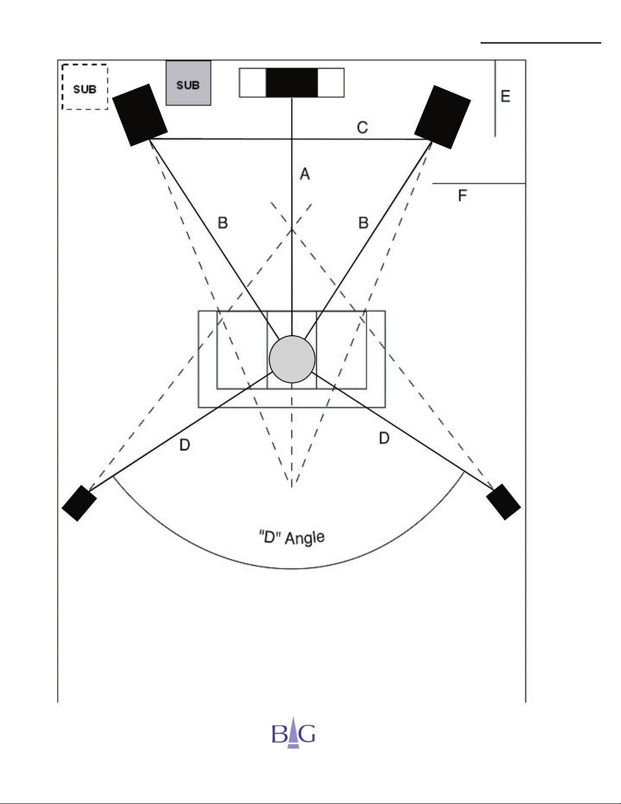
Refer to the diagram on page 7 that depicts a recommended layout for Radia
loudspeakers. This diagram is an overhead view of a typical listening room
with the video screen located at the top of the diagram (the front of the room).
Keep in mind the room is a part of the sound reproduction system and has a
significant effect on the sound you experience, especially at lower frequencies
(see subwoofer setup on page 9).
Locating a loudspeaker close to the wall increases bass output. It may also
increase the boominess of the bass and can artificially alter the loudspeaker’s
tonal balance. We recommend that you spend some time adjusting the
position of the loudspeakers, moving them in and out gradually, to get the
sound you prefer. You may toe the loudspeakers in or out (rotate them around
their vertical axis towards or away from your listening position) to improve
high frequency balance (as indicated by the dashed lines on the diagram). In
general, best results are obtained when the front left and right loudspeakers
have their axis intersecting slightly behind the position of the listener.
The relative location of your listening position to the loudspeakers is important
as well. If possible, do not select a listening position less than three feet (one
meter) from the rear wall of the room. As with adjusting the placement of
your loudspeakers, you can also adjust your listening position to get the most
desirable bass reproduction and high frequency resolution.
The Radia 520i and 420i loudspeakers are dipole devices, which simply
means that sound comes out of the rear of the loudspeaker as well as the
front. For optimum performance they should not be installed inside a cabinet
or alcove.
© BG Corp 2005
5
Page 6

Optimum Setup
Setting Up Your BG Loudspeakers for Optimum Sound
If you plan to use your BG loudspeakers for home theater or multi-channel
audio, here are some additional recommendations.
1. The center channel loudspeaker should be positioned on top of your
television or a shelf directly above or below it. NOTE: The Radia 220i
center channel loudspeaker is magnetically shielded.
2. If you are using a projector, you will need a suitable stand to position
the center channel loudspeaker on the floor in front of the screen or a
bracket above or below the screen. Aim the loudspeaker so it is pointed
at your listening position. The center channel loudspeaker should be
as close as possible to the screen so the voice soundtrack appears to
come from the video image.
Home Theater Applications
The optimum position for all five loudspeakers requires the same distance
from the listening position (i.e. distance A, B and D are equal), see diagram
on opposite page. If it is not possible to get the distances equal, you can
use the delay and level adjustment functions available in most home theater
processors to compensate for the differences in distances.
The diagram shows the optimum placement for the rear loudspeakers. The
subwoofer should be placed beside or behind either the left or right front
loudspeaker. For multiple subwoofers see your authorized BG dealer for
advanced setup procedures.
This manual addresses 5.1 surround sound systems. Where 7.1 or higher
systems are being utilized see your authorized BG dealer for advanced setup
procedures.
6
© BG Corp 2005
Page 7
Optimum Setup
© BG Corp 2005
7
Page 8

Optimum Setup
While rooms vary in size and acoustics, almost any room can be set up
to produce excellent sound with BG loudspeakers. Using a tape measure,
you can easily setup your system properly. The distances you will need to
measure are as follows:
Dimension Description Minimum Optimum Comments
A
B
C
D
“D” Angle
Distance to
screen/center
channel
Distance to main
loudspeakers
Distance between
main loudspeakers
Distance to
surround
loudspeakers
Angle subtended
by surround
loudspeakers
relative to listening
position center
8-12 feet in a typical
7 feet / 2.25
meters
7 feet / 2.25
meters
7 feet / 2.25
meters
90° 120°
room - depends on
viewing distance and
8-12 feet in a typical
room. Up to 60% of
room width in large
room size
rooms
Same as B
Recommend setting the
same as B but as close to
the screen as desired
A careful gradual
adjustment is
recommended
Recommend setting the
same as B
Do not place surround
loudspeakers to the sides
of the listening area
E
F
Room Width
8
Distance between
main loudspeakers
and front wall
Distance between
main loudspeakers
and side walls
Width of listening
room
1 foot / 0.3
meters
10” / 0.25
meters
10 feet / 3
meters
Should be incrementally
adjusted based on
degree of “toe-in”
20% of room width in
large rooms
© BG Corp 2005
Should be slightly greater
than dimension F
Page 9

Subwoofer Setup
Setting Up Your BG Radia 210i for Optimum Sound
The Radia 210i Active Subwoofer by BG Corp is the perfect complement
for our flagship Radia loudspeakers and can be used in all stereo, high
performance home theater or multi channel audio applications. It’s compact
design with powerful performance is the ideal partner to our planar ribbon
loudspeakers. Or feel free to use our 210i subwoofer with any high quality
loudspeaker system.
Featuring a Reactive Canceling Design
TM
, the 210i employs long excursion
KevlarTM woofers that are mechanically coupled via a rigid cylindrical housing.
The twin woofers are mounted with their cones facing in opposite directions
and electrically connected in phase. Recalling Newton’s Law, where for every
action there is an oppostite and equal reaction, the movement generated by
the woofer cones causes the reactive forces of each woofer to effectively
cancel one another. This helps eliminate vibration that could otherwise be
transmitted to the enclosure for cleaner, more detailed bass.
The 210i consists of two 10” long excursion Kevlar
TM
cones, a 500 watt
BASHTM power amplifier and a detachable power cord. Features include
current sensing on/off power control, phase switch, by-pass switch, line-level
input, variable crossover variable volume control- all to deliver lifelike home
theater sound and trouble-free setup.
Processor Setting - We recommend using the small loudspeaker mode on
your processor to protect your loudspeaker’s low frequency drivers from
extremely low bass signals. This will also allow you to achieve more dynamic
range with cleaner sound at higher volumes.
© BG Corp 2005
9
Page 10

Subwoofer Setup
Subwoofer Placement, Connection and Adjustment:
Placement:
The 210i subwoofer should be placed beside or behind either the left or right
front speaker (see diagram). When using more than one subwoofer consult
with your authorized BG dealer for advanced setup procedures.
Connections:
1. L&R line-level input jacks. These inputs are designed for low-level
RCA component connections and interconnects derived directly from
your receiver or processor. If your receiver or processor only has one
subwoofer output plug it into the Right or Left low-level input.
2. Detachable power cord. This subwoofer is supplied with a detachable
power cord for ease of installation and transportation.
10
Adjustments:
1. On/Off power switch. Once the 210i subwoofer is positioned in the room
and the proper cables are installed the on/off switch should be engaged in
the on position for initial power up. The red LED turning on indicates the
unit is powered on.
2. Auto/On switch. With this switch in the Auto position, the amplifier is
in stand-by mode, turning on automatically when the signal arrives from
the receiver and turning off after 10 minutes when the signal is no longer
present. In the ON position, the amplifier is always on regardless of the
presence of the signal from the receiver. For normal use, we recommend
the Auto position.
3. Phase switch. This switch is specifically designed to eliminate phase
discrepancies between the 210i subwoofer and the primary LCR
loudspeaker’s phase. The phase relationship depends on the relative
distance between the subwoofer and the loudspeakers. If the subwoofer
is located within 5 feet (11.5m) from either loudspeaker we recommend
putting the phase switch at 0 degrees. If your subwoofer is located further
than that, experiment with both switch positions and select the one where
the bass sounds the fullest.
© BG Corp 2005
Page 11
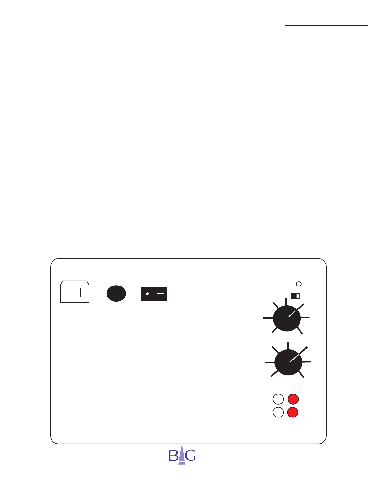
4A 250V
POWER
ON
AUTO ON
PHASE 180 0
IN
OUT
LEFT RIGHT
Diagram of Rear plate,
and amplifier controls
(
)
GAIN
CROSSOVER
MIN
MAX
80
40
120
Subwoofer Setup
Subwoofer Placement, Connection and Adjustment:
Adjustments (cont.):
4. Enabled/Crossover Disabled switch. This switch allows enabling or
disabling the subwoofer’s internal crossover. If you use the LFE output in
your receiver/processor we recommend turning the subwoofer crossover
control knob to 120Hz or disabling it all together. If an external crossover
is used the subwoofer crossover may be disabled.
5. Crossover. This control knob allows adjustment of the cut-off frequency
of the internal subwoofer low pass crossover (filter) within 40Hz-120Hz.
We recommend a setting of 80Hz, which would match the standard cut-off
frequency of the receiver/processor for small loudspeakers. This is also
recommended if using your loudspeakers in Stereo mode since this would
provide optimal integration of the loudspeakers and the subwoofer.
6. Gain Control. This control allows the user to set the loudness level of the
subwoofer relative to the loudspeakers. This will be determined by your
room, source material and personal preference.
© BG Corp 2005
11
Page 12

Special Assembly Instructions
Unpacking Radia 520i / 420i
1. Lay the shipping box down on the floor, ensuring that you have adequate
space to lay the loudspeaker down after removing it from the shipping
box. Note: if your floor is not carpeted, lay a blanket or other suitable soft
fabric on the floor to prevent damage to your loudspeakers.
2. Rotate the box so that the white product label affixed at the factory is on
top and facing up.
3. Pull the top flaps of the shipping box up, taking care not to cut yourself
on the staples used to close the box. Open the other cardboard flaps
to expose the loudspeaker still cradled in it’s protective foam and inside
a protective plastic bag. Remove the foam pieces over the top of the
loudspeaker. DO NOT open box ends.
4. Remove the loudspeaker by lifting it straight up and out of the box. Due
to their weight, we recommend that two people work together to remove
Models 520i and 420i.
Assembly Instructions for 520i / 420i
Loudspeaker
1. Prepare the following tools: a Phillips screwdriver and an Allen (hex)
wrench (located in the packing box).
2. Carefully remove the loudspeaker from the packing box as above. Place it
on a stable surface with a soft cushioning cover (use chairs, a small table
covered with foam or a sofa at least one foot above the floor). Remove
plastic protective film from the glossy part of the base. With the front of
the grill facing up or to the side (Fig. 1) make sure the loudspeaker is
in a stable position. To facilitate the assembly procedure, position the
loudspeaker so the high gloss base is free or has its own support.
12
© BG Corp 2005
Page 13
Special Assembly Instructions
Assembly Instructions for 520i / 420i Loudspeaker
3. Holding the base and using the Allen (hex) wrench remove 1/4” machine
screws from the wooden base (Fig. 1). DO NOT allow the base to rotate
as the upper surface of the base has a glossy finish that can be scratched
by the edge of aluminum extrusion. Depending on how you positioned the
loudspeaker, the base may either drop or the loudspeaker will shift when
the last screw is detached if the loudspeaker does not have support.
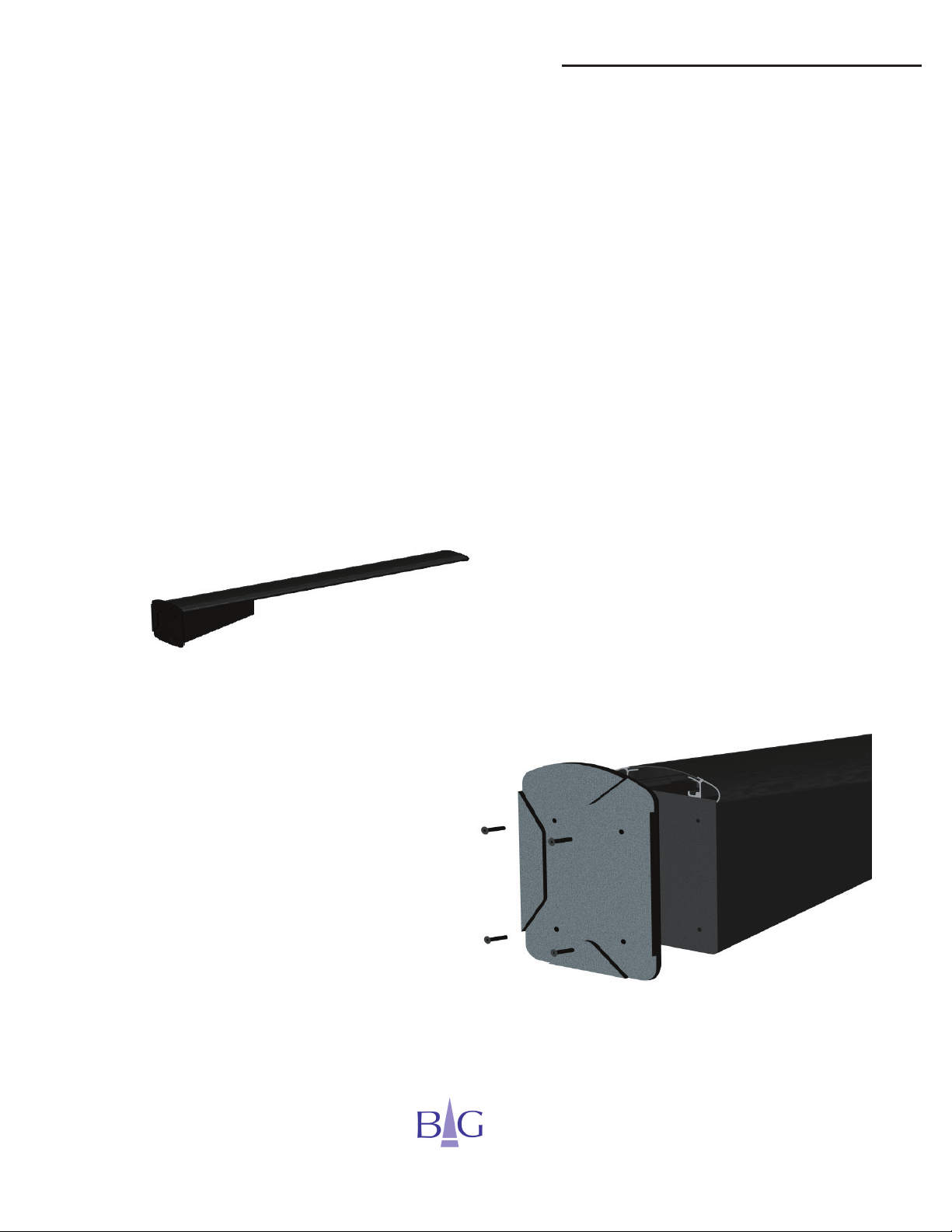
4. Remove the metal stand and spiked feet from the packing box.
Caution! Use care when handling the stand. The spiked feet
are very sharp and can cause injury.
Fig. 1 Removing the base.
13
© BG Corp 2005
Page 14

Special Assembly Instructions
Base Assembly Instructions for 520i / 420i
5. Attach the metal stand as shown in the picture by holding the wooden
base and the metal stand together (Fig.2). Tighten the screws at the
bottom and place the loudspeaker vertically.
NOTE: If you have a hard surfaced floor, the sharp pointed spikes may
scratch the surface when the loudspeaker is set vertically on its feet. Four
protective metal disks are included with your loudspeaker for placement
under the spikes. The disks are small therefore it is recommended you
use a larger protective device, such as stiff plastic or cardboard, that cannot be pierced while positioning your loudspeakers. Replace the protective device with the metal discs after you have finalized placement of the
loudspeakers. Make sure the center of the spike fits directly into the central stabilizing dent located in the center of the metal disc.
Loudspeaker
14
Fig. 2 Attaching the base and the metal stand.
© BG Corp 2005
Page 15
Special Assembly Instructions
Base Assembly Instructions for 520i / 420i Loudspeaker
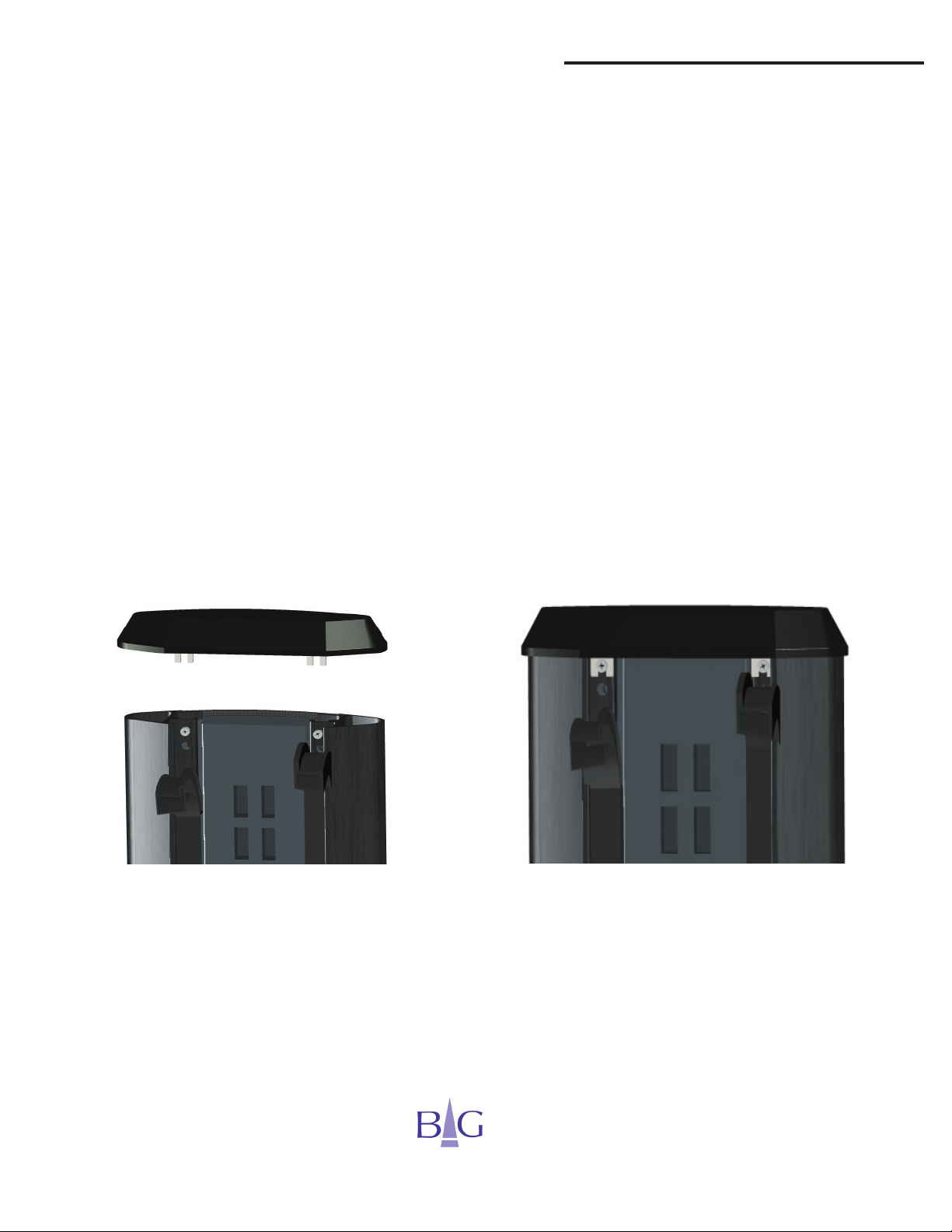
6. Pull away only 3-4” of the top portion of the two rubber inserts located on
the top rear of the loudspeaker (Fig. 3).
7. Locate the high gloss top cap in the packaging. Remove the protective
plastic film from the top cap. Place the top cap on the loudspeaker with
the metal brackets sliding the slotted tabs under the screws. Align the cap
and tighten the screws. Replace the rubber inserts.
8. Assemble the second loudspeaker in the same way. Use the threaded
spiked feet and top caps to level the loudspeakers on the floor for
maximum stability.
Fig. 3 Mounting the top cap.
© BG Corp 2005
15
Page 16

Warranty Information
WARRANTY: All BG loudspeaker systems are warranted to the original purchaser for five years
against defects in materials and manufacture when used in properly designed systems (two years for the
Z-Sub and Radia 210i subwoofers).
Please record your speaker’s information below for future reference.
MODEL: ______________________________
SERIAL NUMBER: ______________________
PURCHASE DATE: _____________________
AUTHORIZED DEALER: _________________
As part of our policy of continual product improvement, BG reserves the right to change or discontinue any
specifications or parts associated with any of its products without advanced notice. Thank you again for
choosing BG loudspeakers.
BG Corp
1780 Forrest Way
Carson City, NV 89706
775-884-1900 ph
775-884-1276 fax
www.bgcorp.com
sales@bgcorp.com
16
© BG Corp 2005
Page 17

NOTES
© BG Corp 2005
17
Page 18

The Power of Clarity
www.bgcorp.com
© BG Corp 2005
 Loading...