

Page 1
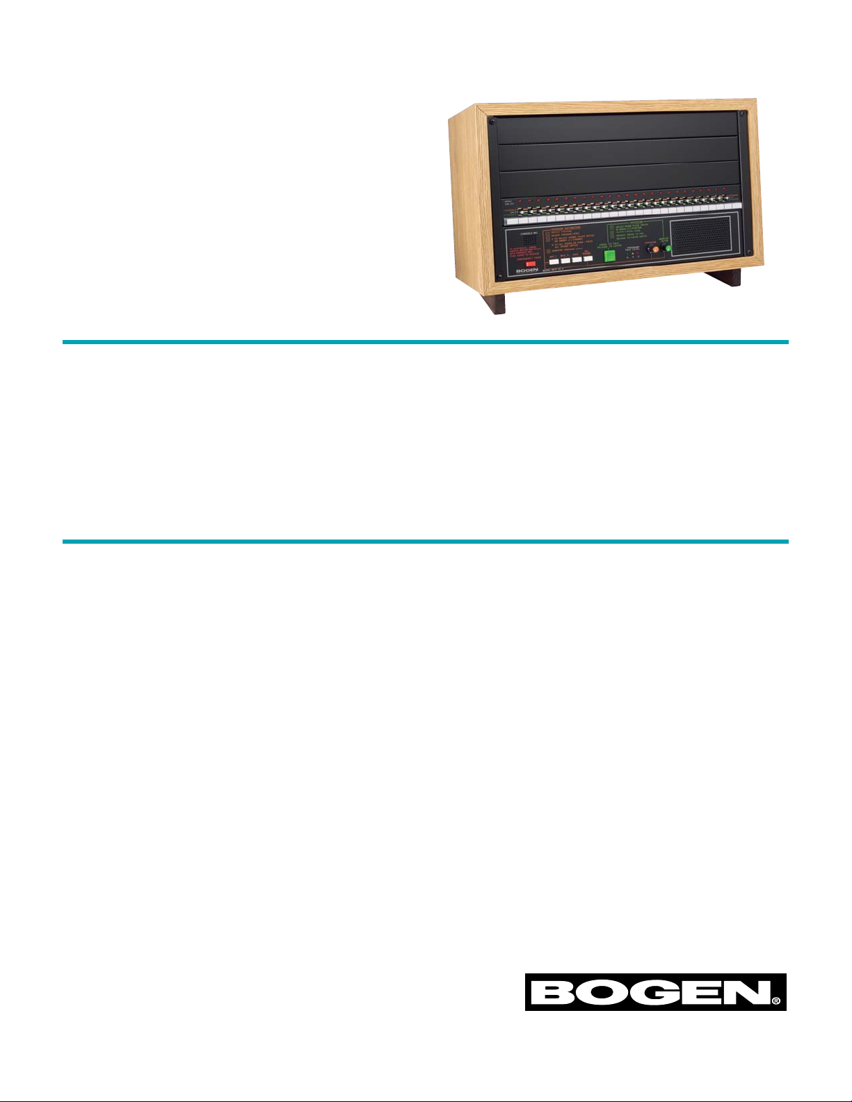
Multi-Graphic
®
Desktop
Control Center
Model SI35A
• Cost-effective communication for 25 to 75 rooms
• Can be furnished with 1, 2 or 3 room selector
panels (each with 25 switches), to accommodate
up to 25, 50, or 75 rooms (model SBA225)
• Step-by-step instructions and color-coded guidelines for easy operation
• Instant Emergency and All Rooms announcements
• Remote emergency paging capabilities
• 20-watt intercom; separate 35-watt program
channel
• Provision for time signalling, telco and voice call-in
• Aural and visual monitoring of program material,
as well as level controls
• Transmit a time tone for classroom change, etc.
• Emergency All-Call with a single push-button
• Emergency announcements take precedence over
all system functions and are transmitted at a predetermined level
• Emergency paging from a remote telephone or
microphone
• Teachers converse hands-free with the control
center operator over their individual classroom
speaker
• Calls to staff locations are announced by a supervisory tone signal, which repeats at regular intervals to indicate that the channel is open and the
room is being monitored
• Classrooms can be equipped with call-in switches
to call the control center, with options for privacy to voice call-in
• A CD player-AM/FM receiver can be installed
when system capacity does not exceed 50 stations
• Sturdy desktop cabinet finished in an attractive
simulated wood grain finish
Features
Description
Specifications subject to change without notice.
© 1995 Bogen Communications, Inc.
Part No. 54-7795-05C 0807
The SI35A provides fast, reliable, and efficient intercommunication and tone signalling in small to medium-sized schools. The SI35A provides a 20-watt intercom amplifier to permit instant intercommunication
with any speaker-equipped location, and a separate 35watt program amplifier for simultaneous distribution
of program material to other rooms or locations. The
system also features an emergency page capability for
emergency announcements to all stations at once.
The SI35A provides complete facilities for distributing
a variety of program materials from optional equipment such as microphones, CD player-AM/FM receiver, or other background music source. Selection of
program material, as well as its distribution to selected rooms is accomplished with simple push-button
program selection and by following the color-coded
guidelines.
Page 2

The school communication Control Center shall be a
Bogen Model SI35A, or approved equivalent. The
Control Center shall be engineered for optimum simplicity of operation, made possible by the use of function-identified push buttons with associated colorcoded guidelines, and supported by step-by-step
instructions printed on the front panel.
Communication Control Centers, which are difficult
to operate and do not provide push-button operation, color-coded guidelines, and operating instructions permanently printed on the panels shall not be
considered. The Control Center shall provide at least
the following features and functions:
1. Direct two-way voice communication between
the Control Center and any classroom or speaker-equipped location, with simultaneous distribution of program material or voice announcements to any other classroom or location.
2. Distribution of voice announcements from the
Control Center to any or all speakers.
3. Facilities for automatically sounding a supervisory tone signal over any loudspeaker selected for
two-way communication, to alert the teacher to
the call, and to prevent unauthorized monitoring.
The tone signal shall sound whenever the classroom is being monitored and shall repeat at regular intervals.
4. Distribution of program material to any or all
classrooms.
5. Ability to transmit a program or announcement
simultaneously to all classrooms by simple operation of a program source push button and the
All Rooms push button.
6. Separate inputs for two low-impedance balanced
microphones and one high-impedance auxiliary
program source (CD player/tuner, etc.). Program
source selection shall be accomplished by simply
pressing the appropriately labeled push button.
7. Aural and visual monitoring of all program material.
8. Facilities for voice call origination to the Control
Center from any classroom equipped with a
voice call origination switch.
9. Facilities for annunciator call-in to the Control
Center from any classroom equipped with a call
origination switch. (Note: Specify Bogen CA10A
Call Switch for this feature.)
10. Facilities to positively prevent the Control
Center from monitoring any classroom whose
call origination switch is in the Privacy position.
(Note: Specify Bogen CA11A Call/Privacy Switch
for this feature.)
11. Provision for the instantaneous distribution of
emergency messages from the Control Center to
all locations equipped with loudspeakers, simply
by pressing a single, red push button. This action
shall override all other programs and bypass all
other controls. The emergency message shall be
transmitted at a predetermined level.
12. Provision for an optional emergency page feature
which shall permit emergency announcements
from a remote telephone or microphone to all
locations equipped with loudspeakers.
13. Classroom call origination with light annunciation
and tone signal at the Control Center. Call origination shall require only a momentary depression
of the call-origination switch, which shall activate
a repetitive tone signal and light the annunciator
lamp associated with the calling classroom. The
annunciator lamp shall remain lit until the call is
answered and then be automatically cancelled.
14. Provision to optionally distribute a classroom
change signal to all speaker-equipped stations.
15. Functionally-identified push buttons and colorcoded guidelines for each function of the Control
Center. The intercom channel shall be identified
by green guidelines. The program channel shall be
identified by amber guidelines. The emergency
page push button shall be red.
16. Provision to include an optional CD playerAM/FM tuner. (Note: Specify Bogen Model
CDR1.)
To fulfill the above requirements, a Bogen Model
SI35A, or approved equivalent Control Center shall
be used, meeting the following technical requirements:
It shall be designed for continuous duty service in
institutional and industrial applications on line voltages of 120 volts, 60 Hz AC, over a temperature range
of 0°F to 130°F. Power consumption of the MCP35A
control panel, at rated output, shall not exceed 100
watts.
It shall include two separate amplifiers. The program
amplifier shall be capable of producing 35 watts RMS
at less than 1% distortion at rated power and bandwidth. The frequency response shall be within +1,
-3 dB from 80 Hz to 15 kHz. The intercom amplifier
shall have an output rating of 20 watts RMS; frequency response shall be shaped for maximum intelligibility. Both amplifiers shall have a balanced 25-volt line
output.
It shall include inputs for two Lo-Z balanced microphones, one Hi-Z unbalanced AUX input, telephone
paging accessories, and booster amplifier. Terminals
shall be provided for the time signalling and telco page
(activation) features.
Architect
and Engineer
Specifications
Page 3

It shall provide all controls necessary for two-way
intercom communication with any classroom, distribution of general announcements or program material
to any or all classrooms, and transmission of emergency announcements to all classrooms. Provisions
shall be included for optional emergency paging from
a remote telephone or microphone.
Complete facilities for aural (monitor speaker) and
visual (LED) monitoring of all program material shall
be provided.
It shall include three-position (Program, Off,
Intercom) room selector switches and associated
LEDs, and Press To Talk, All-Call, and Emergency Page
push buttons. The Emergency switch shall gather all
station lines to permit single push-button distribution
of announcements to all speaker locations. Similarly,
the All Rooms switch shall permit single push-button
distribution of program material to all speaker locations, except for those on the intercom channel.
It shall include facilities for voice-call origination from
classrooms and for selective classroom privacy; the
latter shall prevent the Control Center from monitoring any classroom whose call origination switch is
in the Privacy position.
The Control Center shall measure 20-1/2" W x 14" H
x 11" D (with sloped top). The cabinet shall be constructed of sturdy material and finished in simulated
wood grain finish; control panels shall be finished in
black. Shipping weight shall be 35 lb.
(Also include all program source equipment, classroom loudspeakers, call origination switches, and
other associated material, hardware and cable
required.)
The system shall be supplied or installed by or under
the direct supervision of an authorized local distributor who has been trained by the manufacturer in the
proper installation, operation, and service of the
equipment.
Architect
and Engineer
Specifications
(continued)
Page 4

50 Spring Street, Ramsey, New Jersey 07446, U.S.A.
Tel. 201-934-8500; FAX: 201-934-9832; www.bogen.com
Rated Output: Program – 35WRMS
Intercom – 20WRMS
Frequency Response: Program – +1, -3 dB from 80 Hz to 15 kHz
Intercom – Shaped for maximum intelligibility
Distortion: Less than 1% at rated power and bandwidth
Inputs: Two Lo-Z balanced MIC: Hi-Z unbalanced AUX; Telco Page; 25V Booster
Output: 25V Balanced line, Line Out to Booster
Input Sensitivity: Program – MIC Input: 300µV balanced Lo-Z; AUX: 100mV unbalanced Hi-Z
(for rated output) Telco Page: 100mV unbalanced Hi-Z; Intercom – Listen Mode: 300µV
balanced Lo-Z (Console MIC: 1mV unbalanced Lo-Z)
Controls: Front Panel – Program Selection: MIC 1, MIC 2, AUX; Level: Monitor/
Listen, Program; Distribution: All Rooms, Emergency, Press To Talk;
Indicators: Program Talk/ Level LED
Rear Panel – Input Gain: MIC 1, MIC 2, AUX, Telco Page, Talk, Listen
Internal – Gain: Emergency Page, Supervisory Tone, Time Tone
Enable/Disable: MIC 1/Console MIC; MIC 2/Telco Page, Phantom Power,
Supervisory Tone, MIC 1/Monitor Mute
Tone Specifications: Time Tone – 750 Hz
Supervisory Tone – Repeating, 500 Hz
Call-in Tone – Repeating; oscillates between 500 Hz and 750 Hz (Switching Freq., 16 Hz)
Power Requirements: 120V AC, 60 Hz, 100W maximum
Dimensions: 20-1/2" W x 14" H x 11" D (with sloped top)
Cabinet: Simulated wood grain finish
Panels: Black with color-coded lines and instructions for Intercom, Program, Emergency Page
Shipping Weight: 35 lb.
Operating Temp.: 0-130° F
Accessory Equipment: CDR1 – CD player and AM/FM Receiver
SCR25A – Call-in module (for switches w/o SCR)
SBA225 – Three-Channel (Program A, Off 0, Intercom C), 25-Station Switchbank
WMT1A – Line-matching transformer for telephone paging
TAMB – Telephone access module for telephone paging
DDU250, MBS1
000A – Desktop paging microphones
CA10A, CA11A, CA17 – Call-in switches (2-pos., 3-pos., and push-button, respectively)
TWK351 – 2-Wire call-in adapter kit
2518, 2520, 2522 – Connector Kits (18-, 20-, and 22-gauge respectively)
TL156 – Insertion Tool for connector kits
Technical
Specifications
 Loading...