

Page 1

Infrared Voice Reinforcement System
© 2011 Bogen Communications, Inc.
All rights reserved.
Specifications subject to change without notice.
54-2197-01G 1306
Page 2
CAUTION
RISK OF ELECTRIC SHOCK DO NOT OPEN
CAUTION: TO PREVENT THE RISK OF ELECTRIC SHOCK, DO NOT REMOVE
ANY FRONT/BACK COVERS OR PANELS. NO USER-SERVICEABLE PARTS
INSIDE.
REFER SERVICING TO QUALIFIED PERSONNEL.
The exclamation point within an equilateral triangle is intended to
alert the user to the presence of important operating and maintenance (servicing) instructions.
The lightning flash with arrowhead symbol, within an equilateral
triangle, is intended to alert the user to the presence of uninsulated
"dangerous voltage" within the product's enclosure that may be of
sufficient magnitude to constitute a risk of electric shock to persons.
CAUTION
DANGER OF EXPLOSION IF
TRANSMITTER BATTERY IS
INCORRECTLY REPLACED.
REPLACE ONLY WITH SAME
OR EQUIVALENT TYPE
WARNING
BATTERY SHALL NOT BE
EXPOSED TO EXCESSIVE
HEAT SUCH AS SUNSHINE,
FIRE, OR THE LIKE.
NOTICE: Every effort was made to ensure that the information in this guide was complete and accurate at the
time of printing. However, information is subject to change.
WARNING: To reduce the risk of Fire or Electric Shock, Do Not Expose this apparatus to rain or moisture.
Apparatus shall not be exposed to dripping or splashing and no objects filled with liquids, such as
vases shall be placed on the apparatus.
WARNING: Only connect unit to AC mains outlet providing protective earthing connection.
NOTE: Mains plug or an appliance coupler are used as disconnect devices from the mains and shall remain
readily accessible and operable.
CAUTION: These servicing instructions are for use by qualified service personnel only. To reduce the risk of
electric shock, do not perform any servicing other than that contained in the operating instructions
unless you are qualified to do so.
Always follow these basic safety precautions when installing and using the unit:
IMPORTANT SAFETY INSTRUCTIONS
1. Read these instructions.
2. Keep these instructions.
3. Heed all warnings.
4. Follow all instructions.
5. Do not use this apparatus near water.
6. Clean unit with dry cloth.
7. Do not block any ventilation openings. Install in accordance with the manufacturer's instructions.
8.
Do not install near any heat sources such as radiators, heat registers, stoves, or other apparatus
(including
amplifiers) that produce heat.
9. Do not defeat the safety purpose of the polarized or grounding-type plug. A polarized plug has two blades
with one wider than the other. A grounding-type plug has two blades and a third
grounding prong. The wide
blade, or the third prong, are provided for your safety. If the provided
plug does not fit into your outlet, con-
sult an electrician for replacement of the obsolete outlet.
10. Protect the power cord from being walked on or pinched particularly at plugs, convenience receptacles,
and the point where they exit from the apparatus.
11. Only use attachments/accessories specified by the manufacturer.
12. Unplug this apparatus during lightning storms or when not used for long periods of time.
13. Refer all servicing to qualified service personnel. Servicing is required when the apparatus has been
damaged in any way, such as power-supply cord or plug is damaged, liquid has been spilled or objects have
fallen into the apparatus, the apparatus has been exposed to rain or moisture, does not operate
normally, or has been dropped.
Page 3

Table of Contents
Description ......................................................................................................................1
Package Contents ..........................................................................................................1
ORB35 Receiver/Base Unit Front Panel ......................................................................2
ORB35 Receiver/Base Unit Rear Panel ........................................................................2
OMX1 MIC/Transmitter Panels ......................................................................................3
ORS Infrared Sensor ......................................................................................................3
Quick-Start Installation Instructions ............................................................................4
Setting System Volumes ................................................................................................4
ORB35 Receiver/Base Unit Installation & Operation................................................5-8
Mounting & Ventilation ..........................................................................................................5
System Wiring Connections ..............................................................................................5-6
Receiver/Base Unit Programming DIP Switches ..................................................................7
Controls & Indicators ............................................................................................................8
Charging Dock Indicators ......................................................................................................9
Charging OMX1 MIC/Transmitter Units ................................................................................9
ORB35 Rotating Cover..........................................................................................................9
OMX1 MIC/Transmitter ............................................................................................10-12
Battery Installation ..............................................................................................................10
OMX1 Features ..................................................................................................................10
Programming the OMX1......................................................................................................10
Dock Selection Tabs ............................................................................................................11
Controls and Indicators ........................................................................................................11
Function Buttons..................................................................................................................12
OMX1 Wearing Options ......................................................................................................12
OMX1 Adjustable Lanyard Assembly ..................................................................................13
ORS Infrared Sensor ....................................................................................................14
Installation............................................................................................................................14
Technical Specifications ..............................................................................................15
Limited Warranty; Exclusion of Certain Damages ....................................................16
Accessories ..................................................................................................................16
Page 4

This Page Intentionally Left Blank.
Page 5

1
Description
The Bogen Orator is a dual-channel, infrared (IR) wireless microphone/transmitter and mixer/amplifier system that is designed
to enhance a presenterʼs voice in all areas of the room. IR technology eliminates the interference and cross-talk from adjacent
rooms that occurs with radio-based wireless products. In addition to two independent wireless microphone/transmitter
channels, the receiver/base unit (ORB35) provides 4 AUX inputs for the connection of various source devices like the audio
output of a computer, a video projector, a DVD player, and other audio sources. A separate Override input allows its audio
source to take precedence over the AUX inputs. Typically, this input is connected to the facilityʼs area-wide paging system so
that important announcements can be clearly heard through the Orator system. A highly functional 8-Band equalizer allows a
tremendous amount of control to compensate for room acoustics. A single, convenient, master volume control provides an
easy means of adjusting the overall system level.
The Orator uses a centrally located ceiling sensor (ORS) to receive infrared signals from its MIC/Transmitter units (OMX1).
Each OMX1 contains a built-in microphone and is designed to be used as a pendant microphone suspended from a neck-worn
lanyard (with safety break-away latch) or as a handheld microphone. A professional style wire belt clip and external microphone
input allows the OMX1 to be used as a body-pack if desired. A compatible, external microphone must be obtained
separately for this use. The OMX1 also contains an AUX input jack for connection to audio source devices. This function of the
OMX1 allows audio devices to be easily and wirelessly connected into the Orator system.
The ORB35ʼs unique front-mounted charging docks and rotating cover provide a place for secure storage and charging of the
OMX1 units. Users always know where the charging docks are and this configuration eliminates the need to find an unused
outlet and a suitable spot to put the charger itself. The Oratorʼs cover rotates up and out of the way when the system is in use
and back down to help secure the OMX1 units when not in use. A key lock allows the cover to be locked in the closed position,
and also in the open position if the rotating cover function is not desired. The lanyard can be left attached to the OMX1 while
in the charging dock with the lanyard itself neatly tucked away in the storage area below the charging dock.
Each OMX1 unit is capable of muting the other OMX1 in the system or of initiating an intercom call request to a compatible
facility intercom system. The front area contains two function buttons specifically for these features. A simple press of one
button initiates an intercom call. Pushing and holding the other button will cause the other OMX1 to be muted. These features
can be enabled or disabled per OMX1 through the ORB35 unit. The OMX1 itself contains no switches for setting these features
or its transmit frequency. Instead the OMX1 communicates with the ORB35 unit when it is inserted into the charging dock.
The ORB35 unit syncs the OMX1 with frequency to transmit on and what specific functions are to be enabled. All settings are
made on the rear of the ORB35 unit.
Along with all this innovation comes Bogenʼs proven amplifier reliability. The same industrial grade amplifier technologies
that have made Bogen a staple of commercial public address systems for over 80 years are used in the Orator. Highly
dependable electronic components and robust amplifier designs wrapped in heavy-gauge steel enclosures ensure years of
operational service.
Package Contents
The Bogen Orator System comes complete with the following items:
• 1 Receiver/Base Unit (ORB35)
• 2 Security Cover Keys
• 1 or 2 MIC/Transmitters (OMX1)
Orator 1 System includes 1 OMX1 unit;
Orator 2 System includes 2 OMX1 units
• 2 Dock Selection Tabs (per OMX1)
• 1 Lanyard (per OMX1)
• 1 Lanyard Attachment Plate (per OMX1)
• 1 Rechargeable Li-Ion Battery (per OMX1)
• 5 Blank Identification Label Cards (per OMX1)
• 1 Infrared Sensor (ORS)
• 1 Sensor Cable - 50 ft. (15m) approx.
• 1 Sensor Mounting Bracket (with hardware)
Page 6
2
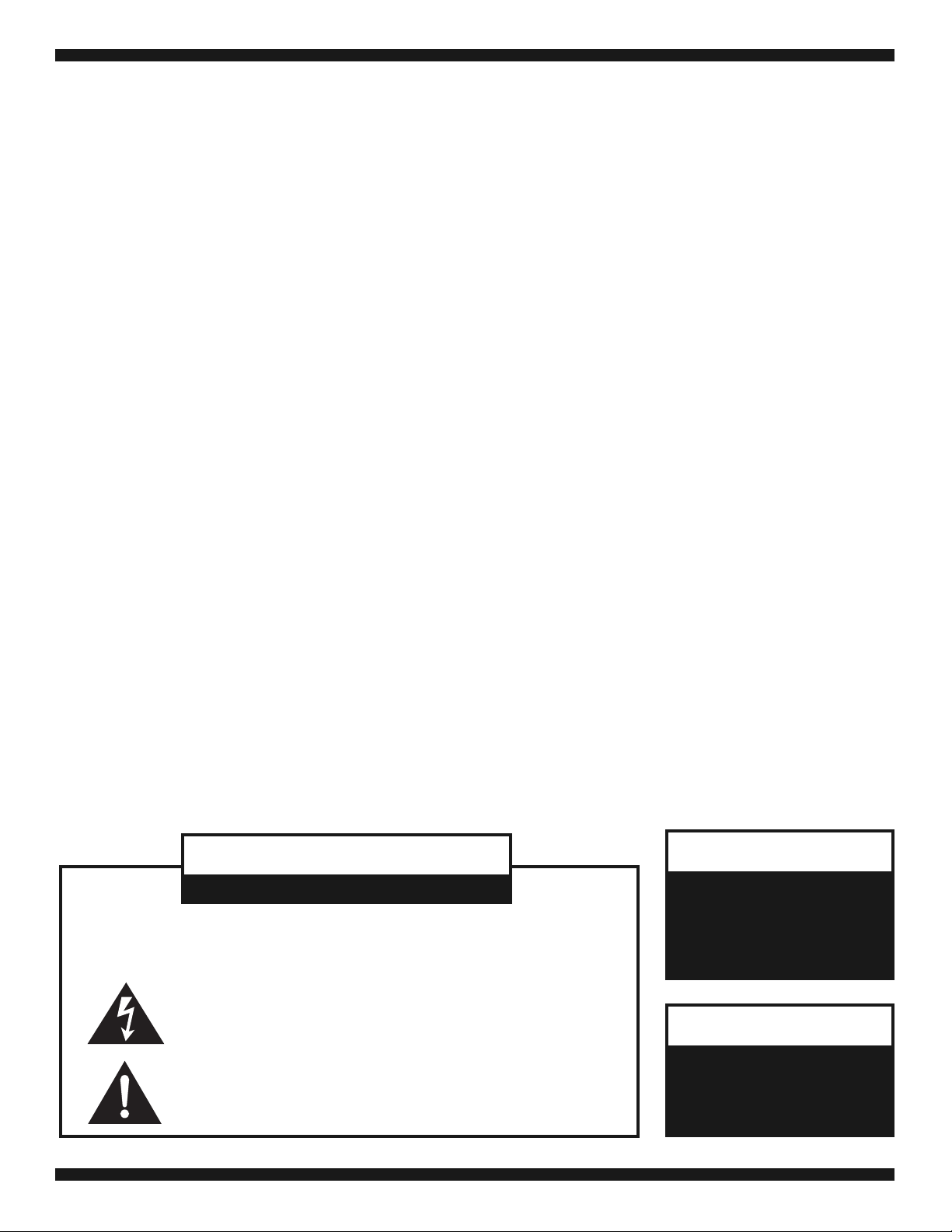
ORB35 Receiver/Base Unit Front Panel
1. Power Switch - page 8
2. Rotating Security Cover Lock
3. Translucent Rotating Security Cover - page 9
4. Built-In Charging Docks - page 9
5. ALD Program Monitor Outputs - page 6
6. Input 4 Connections - page 6
7. AUX Input Volume Controls - page 8
8. Master Volume Control - page 8
9. Bass & Treble Controls - page 8
10. MIC/Transmitter Charge Status Indicators - page 9
11. Lanyard/Accessory Storage Area
5
1
2
3
4
6
7
8
9
10
11
1
2
7
3
4
5
6
9
10
12
11
13
8
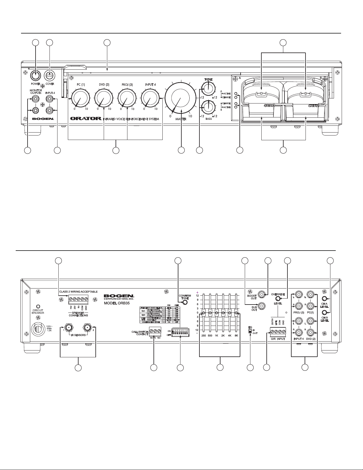
1. Speaker Connections - page 5
2. Confirmation Tone Volume Control - page 8
3. Line-Level Subwoofer Output - page 6
4. Line-Level Boost Output - page 6
5. Override (O/R) Input Volume Control - page 8
6. MIC/Transmitter(s) Volume Control - page 8
7. IR Sensor Connections - page 5
8. Call Switch Contact - page 6
9. Setup/Configuration DIP Switch - page 7
10. 6-Band Graphic EQ - page 8
11. EQ Bypass Switch - page 8
12. Override (O/R) Input - page 6
13. AUX Inputs - page 5
ORB35 Receiver/Base Unit Rear Panel
Page 7

3
OMX1 MIC/Transmitter Panels
ORS Infrared Sensor
1. AUX Input Jack - page 11
2. Charging Dock Selector Tab - page 11
3. Call-In Push Button - page 12
4. Recessed Volume Control - page 11
5. Built-In Microphone - page 11
6. Battery Life Status LED - page 11
7. MUTE Push Button - page 12
8. ON/ OFF /Local MIC Mute - page 11
9. Emitter Lens
10. External Microphone Input - page 11
11. Durable Spring Wire Belt Clip - page 13
12. Removable Lanyard Plate - page 13
13. User ID Card Area - page 12
14. Battery Door - page 10
15. Charging Contacts (underside) - page 9
1
3
4
5
6
7
8
10
11
12
15
2
13
9
14
1. Surface Mounting Holes
2. T-Bar Bracket Screw Holes
3. Coax Cable Connector
4. Safety Tether
1
2
3
1
1
1
2
4
REAR
VIEW
FRONT
VIEW
Page 8

4
Follow these steps to get the Orator System up and functioning quickly. These instructions assume that you are already familiar
with the installation of commercial paging and sound equipment. If you are not, please take the time to read the full instructions
before beginning the installation.
1) Mechanically mount the ORB35 Receiver/Base Unit.
2) Mechanically mount the Sensor and then run the sensor cable back to the ORB35. Details on page 14.
3) Connect the coaxial sensor cable to either IR Sensor 1 or 2. Details on page 5.
4) Connect speakers (previously mounted) to appropriate ORB35 speaker terminal. Details on page 5.
5) Turn CH A and CH B level controls to half rotation, the Master Volume to 0, set all DIP switches to their down (0) positions,
set the EQ switch to OUT, and set 4 AUX Input controls to 0. Details on page 8.
6) Plug the ORB35 unit into an AC outlet and press the power switch to turn the unit on. Check that the indicator light around
the power switch is illuminated. Details on page 8.
7) Install batteries into the OMX1 units. Batteries have a partial charge and can power the OMX1 immediately, but will need to be
fully charged for full use. Details on Page 10.
8) IMPORTANT: After battery installation, put each OMX1 into a different charger dock momentarily. This will program each OMX1
with the proper transmit frequency channel selected and any other features.
9) Remove from charging dock and turn on the OMX1 units by pressing the power switch on the side of each unit. The Active indi-
cators near the charging bays should illuminate as each OMX1 is turned on. The OMX1 Volume Control should be turned to “10”.
10) Slowly turn up the Master Volume Control while speaking into each OMX1ʼs built-in microphone until the audio can be heard.
Test each OMX1 for audio transmission. Adjust the systemʼs volume controls as needed.
The Orator system is now proved out and functioning. Turn off the power to the ORB35 unit before making any other
connections. Review the full instructions for information on enabling OMX1 functions, setting up the Override input, and using the
8-Band EQ among other system operation details.
Quick-Start Installation Instructions
Setting System Volumes
For best operation, the volume controls of the OMX1 MIC/Transmitters should be set to 10 and then adjust the CH A and CH B
level controls and the Master Volume control for best gain before feedback. Initially during this process, a good place to set the
Master Volume control is at half rotation. CH A and CH B are then trimmed to just before feedback using whichever MIC/Transmitter
is going to be used in the system (built-in or external microphone). This approach limits the amount of system gain the user can
add which helps avoid large feedback squeals during live voice operation. When using an audio source into the OMX1ʼs AUX input,
both the OMX1ʼs volume control and the audio sourceʼs volume should be used to set the desired level.
When audio sources are connected to the ORB35 receiver/base unitʼs AUX or Override inputs, their associated individual volume
controls and also any on the audio source, should be used to set the desired volume level. If for some reason the master volume
needs to be readjusted because of sources connected to the ORB35, the CH A and CH B volumes should be readjusted to ensure
good output before feedback is available.
Page 9

ORB35 Receiver/Base Unit Installation & Operation
Mounting and Ventilation
Rack Mount
Rack mount brackets (RPK92) are available as an accessory. The feet on the ORB35 Receiver/Base unit must be removed before
rack mounting the unit. The receiver/base unit is passively cooled and requires proper ventilation. One empty rack space above
and below the receiver/base unit (Model ORB35) should be provided to ensure proper ventilation. The receiver/base unit should
not be positioned immediately above other equipment that produces significant heat.
Shelf Mount
The receiver/base unit has attached feet that make it suitable for resting on a level surface. The feet provide the necessary ventilation space below the unit. A minimum of 1” of space above the amplifier is also required. If stacking the ORB35 unit with other
equipment, be sure that the necessary space is left above the unit and that the equipment directly below the receiver/base unit does
not produce significant heat.
System Wiring Connections
IMPORTANT: Turn the ORB35 Receiver/Base Unit OFF before making any electrical connections.
Speakers (Rear)
A pluggable screw terminal connector provides access to the speaker output connections. Connect the appropriate type of speaker
load to the specific output type.
IMPORTANT: Do not connect to more than one speaker output type.
70V and 25V Outputs
70V and 25V outputs typically require speakers with transformers to step down the speaker
drive voltage. The total load in watts of all the speakers connected to the 70V or 25V
output cannot exceed the unitʼs output power rating. Make connections to the COM terminal
and either the 70V or 25V terminals as determined by the speaker specification or application. All speaker outputs are transformer-coupled and have no reference to earth ground.
If it is desired to have the speaker system ground referenced, then a jumper wire can be
connected between COM and GND terminals.
8-Ohm Output
When connecting to the 8-ohm output, the combined load of all the speaker impedances
cannot be less than 8 ohms. Connecting a load higher than 8 ohms will not harm the unit,
but full rated output power will not be delivered to the speaker load if its impedance is higher
than 8 ohms. Make connections to the 8-ohm and COM terminals. All speaker outputs are
transformer-coupled and have no reference to earth ground. If it is desired to have the
speaker system ground referenced, then a jumper wire can be connected between COM
and GND terminals.
AUX Inputs (Rear)
The ORB35 unit provides 4 line-level AUX inputs for connections to various audio source devices.
All inputs are stereo combining RCA jack inputs that convert stereo inputs to mono. Mono sources can
be connected to either of the RCA jacks for the input with the other jack left unconnected
.
IR Sensors (Rear)
The coaxial cable from the IR sensor must be connected to either IR Sensor 1 or 2. The second
input is provided for situations where one sensor cannot provide adequate coverage for the
application, and an additional sensor might need to be connected.
5
•
•
PLEASE READ THIS BEFORE INSTALLATION: Before the MIC/Transmitter OMX1 will work in the Orator system, it
must first be programmed by inserting it into a charging dock. In systems with 2 OMX1 units, each must be inserted
into a different dock. Inserting both OMX1 units into the same dock will result in both MIC/Transmitters operating on
the same channel frequency, which should be avoided. See page 7 for more information on programming the OMX1
MIC/Transmitters.
Page 10

6
ORB35 Receiver/Base Unit (contʼd)
Call Switch Contacts (Rear)
Function buttons on the OMX1 can be activated to cause a relay contact in the ORB35 unit
to cycle for the purpose of signaling a call-in from the room to the facilityʼs intercom
system. Both normally open and normally closed contacts are provided. Connect the appropriate contact type to the call-in signaling circuit for the intercom system in use.
Override Input (Rear)
The ORB35 unit provides an override input which is compatible with a wide range of input
devices. 25V and 70V speaker lines can be directly connected to the override input as well
as a line-level signal. These connections are transformer-coupled and are not referenced to
ground. If it is desirable to reference the input to ground, place a jumper wire between COM
and GND terminals.
• Connect a 25 or 70V speaker line to the 25/70V and COM terminals to trigger an override
when the speaker line becomes active.
• Connect a line-level input to the LINE and COM terminals to trigger an override when this
source becomes active.
The Override Input is always connected to the amplifierʼs internal mix bus. When an override
is triggered, the AUX inputs of the ORB35 are muted, allowing the Override Input to take
priority over the audio program from the ORB35 Receiver/Base Unit. The OMX1 inputs are
active during an override page.
Boost Out (Rear)
The Booster output RCA jack provides a line-level output of the program at the speaker
outputs including all volume adjustments and EQ settings. This output is typically used to
feed an external amplifier to increase the power available for the application.
Sub Out (Rear)
This RCA jack provides a line-level low-passed version of the Boost output. This output is provided for connection of a powered subwoofer, if available.
Input 4 (Front)
The front-mounted Input 4 is wired in parallel with the rear-mounted Input 4. Both inputs
should not be connected to source equipment at the same time. See the section on AUX
inputs for more information about this input.
Monitor Outputs (Front)
Two different styles of monitor output jacks are provided on the front of the receiver/base
unit. These styles are provided to improve the compatibility with devices such as Assistive
Listening Devices or recording equipment. The Monitor outputs provide a line-level signal
with the same program as the speaker outputs including all volume adjustments and EQ
settings (Pre Master Volume).
AC Line Cord (Rear)
Connect the AC line cord to a 120V AC grounded outlet (5-15R or greater).
Page 11

7
ORB35 Receiver/Base Unit (contʼd)
Receiver/Base Unit Programming DIP Switches
Programming DIP Switch (Rear)
The 8-position DIP switch allows several of the systemʼs operational parameters to be set.
NOTE: Uses of labels “A” and “B” below for the OMX1 refer to which charging dock
the OMX1 was previously inserted in. OMX1 parameters, such as transmitting
frequencies and enabled functions are synced with the ORB35 unit each
time an OMX1 is inserted in one of the charging docks. Inserting an OMX1 into
Dock A will give it those
associated functions. Likewise inserting the same OMX1
into Dock B will instead give it the “B” setting attributes
.
SWITCH:
#1. The Orator can operate on two different frequency bands. Dual-band operation is provided
to improve the systemʼs ability to avoid interference sources within the environment.
When possible, it is best to use the low band since the OMX1ʼs battery life will be
increased in this band.
# 2. Setting this switch to ON allows the “A” OMX1 to mute the audio of the “B” OMX1, when-
ever the Mute function button on the “A” OMX1 is depressed. Setting the switch to
OFF disables this feature. See the OMX1 section for information on this function button.
#3. Setting this switch to ON allows the “A” OMX1 to initiate a call-in to the facilityʼs intercom
system whenever the Call-In function button on the “A” OMX1 is depressed. Setting the
switch to OFF disables this feature. See the OMX1 section for information on this
function button.
IMPORTANT: The Orator Call-In feature is provided as a convenience for the user and is not
intended to be used as a personal safety device. In an emergency situation,
the Call-In device provided with the intercom system should be used.
# 4. Setting this switch to ON allows the “B” OMX1 to mute the audio of the “A” OMX1, when-
ever the Mute function button on the “B” OMX1 is depressed. Setting the switch to
OFF disables this feature. See the OMX1 section for information on this function button.
# 5. Setting this switch to ON allows the “B” OMX1 to initiate a call-in to the facilityʼs intercom
system whenever the Call-In function button on the “B” OMX1 is depressed. Setting
the switch to OFF disables this feature. See the OMX1 section for information on this
function button.
IMPORTANT: The Orator Call-In feature is provided as a convenience for the user and is not
intended to be used as a personal safety device. In an emergency situation,
the Call-In device provided with the intercom system should be used.
#6.Determines the threshold level that will trigger an Override Mute. The LOW will
allow an override mute to be triggered by a smaller input signal. The HIGH setting will
require a larger input signal to cause an override mute. This switch is useful in situations
where the override input source is noisy and may cause false override muting.
#7. Determines the length of time after a triggered mute un-mutes the other inputs. The
“SHORT” setting provides a delay suitable for most paging applications; the “LONG”
setting provides a delay approximately twice as long (for atypical paging situations).
#8. Turn the confirmation tone ON or OFF.
Page 12

8
ORB35 Receiver/Base Unit
Controls & Indicators
Power Switch (Front)
The soft touch power switch turns the ORB35 Receiver/Base Unit on and off. A green
indicator ring around the power switch indicates that the Orator is powered on. This indicator
is extinguished when the Orator is off. Charging and communication between OMX1
MIC/Transmitters still continue when the ORB35 is powered off.
AUX 1 – 4 Level Controls (Front)
Each of the AUX inputs has an associated level control located on the ORB35 unitʼs front
panel to adjust its level and the overall balance with other inputs.
Master Volume Control (Front)
A large Master Volume Control is located on the front of the ORB35 unit. The levels of all
inputs are simultaneously changed by adjustments to this control. However, the confirmation
tone is unaffected by this control.
Bass and Treble Controls (Front)
A Bass and a Treble control are provided on the front of the ORB35 base unit to allow users
to adjust the high and low frequency response of the system.
EQ Bypass Switch (Rear)
To use the EQ, this switch must be in the IN position. When the switch is set to the OUT
position, the slider controls will have no effect, but the Bass and Treble controls on the front
of the unit will continue to work.
6-Band Graphic EQ (Rear)
In addition to the front-mounted bass and treble controls, a rear mounted 6-band graphic EQ
is provided to allow precise control of system tonal response. The EQ bypass switch must
be set to IN for these 6 controls to operate.
Override Level Control (Rear)
Sets the Override Input Level to the mix bus. Detection of override audio for muting other
inputs is done before the control so its setting has no effect on the signal level required to trip
an override.
MIC/Transmitter Level Controls (Rear)
Each OMX1 channel has its own level control located on the rear of the ORB35 unit. The
OMX1 has a local level control. When setting the initial levels, the OMX1ʼs level controls
should be set to 10 and the channelʼs rear level control should be set so that feedback (howling/squealing) from the OMX1ʼs microphone is not occurring. Users can reduce the level at
the OMX1 itself since this will not result in feedback.
Confirmation Tone Level Control (Rear)
When enabled by the DIP Switch setting, the ORB35 unit will acknowledge that certain
functions were received or triggered by emitting a short confirmation tone over the system
speakers. The confirmation tone level control is provided to trim the level of these tones.
The level of the confirmation tone is not affected by the master volume control.
Page 13

Charging Dock Indicators
Active
Indicators near the charging docks report the status of the two OMX1 channels. When a
channelʼs associated active indicator is illuminated, the channel is receiving valid IR
transmissions.
Charge
When OMX1 is being charged, the indicator illuminates GREEN. Charging is complete when
the indicator is extinguished. A fault condition is signaled by a RED indicator. A fault condition may indicate a problem with the battery.
IMPORTANT: When replacing batteries use only Bogen P/N 45-7543-05.The use of other
batteries will void the warranty and may result in product damage or fire.
Charging OMX1 MIC/Transmitter Units
OMX1 units are inserted into the charging dock with their front facing up and their tops facing out as shown. If the OMX1 has a dock selection tab installed (see page 11), it will only fit
into one of the docks. The charging docks have a retention feature to hold the OMX1 against
the charging contacts at the bottom of the dock. A mechanical
click is noticeable when the OMX1
is fully inserted into the dock. When
an OMX1 is inserted, its charge
indicator will illuminate shortly
thereafter. You may also hear a
confirmation tone over the system
speakers if the unit is powered on
and the confirmation tone feature
has been enabled. The ORB35
receiver/base unit does not have to
be powered on for the OMX1
MIC/Transmitter units to charge.
The charge indicator will extinguish
when fully charged.
The ORB35 Receiver/Base unit includes a rotating cover.
A key lock to the left of the cover allows it to be locked to
provide a measure of security to the OMX1 units and
accessories when they are not in use. The cover lock can
be left unlocked so the cover can operate freely or it can
be locked in the open position when the cover feature is
not desired.
To open the cover when unlocked, use tab or finger hole
on the lower left of the cover to rotate the cover up. If in
the open position and unlocked, pull on the coverʼs tab
and rotate closed. The coverʼs operation is mechanically
dampened.
9
ORB35 Receiver/Base Unit
ORB35 Rotating Cover
When storing the OMX1 MIC/Transmitter
into the ORB35 Loading Dock for charging,
insert it on a slight angle, with the front face
of the OMX1 pointing up.
Charging
Contacts
SIDE
VIEW
MIC/Transmitter
Accessory Storage Area
OMX1
FRONT
VIEW
“A” Programmed OMX1
Dock Selection Tab is towards
the center of dock station
“B” Programmed OMX1
Dock Selection Tab is towards
the center of dock station
Page 14

Battery Installation
The OMX1 operates on a single, Li-ion rechargeable battery (included). Use only the Bogen P/N 45-7543-05 battery for
replacement. To install the battery, first remove Battery Door (A) from rear of the OMX1 MIC/Transmitter by pulling back on the small
latch. Insert the battery connector (B) into the unitʼs receptacle (C), and feed the batteryʼs cables up into the unit body. Gently slide
the rechargeable battery (D) up into the OMX1, taking care NOT
to crimp or tangle the battery wires. After inserting the battery,
replace the Battery Door securely by engaging the small latch with a “click”.
OMX1 Features
The Orator systems allow for simultaneous operation of two OMX1 MIC/Transmitters.
Each OMX1 has the following features (See Panel section on OMX1 on page 3):
Programming the OMX1
BEFORE USING FOR THE 1ST TIME, PUT EACH OMX1 UNIT INTO A DIFFERENT CHARGE DOCK FOR 2 SECONDS.
There are no setup switches on the OMX1 itself. All setup and programming of the OMX1 is done through a communications link
between the ORB35 unit and OMX1. Programming switches on the ORB35 unit allow a charging dock to enable or disable functions
for the OMX1 that is inserted. Inserting an OMX1 into Dock A will sync that OMX1 with the particular transmitting frequency and other
functional attributes determined by the “A” programmed features. Inserting that same OMX1 into Dock B will change all the operational attributes to those determined by the “B” programmed features. Please note that programming both OMX1 units in the same
dock will result in the system not working since both OMX1 units will be operating on the same transmit frequency. Typically inserting
OMX1 units into separate docks is done as a matter of course when both OMX1 units are being recharged.
If the ORB35 unit is on when an OMX1 is inserted into its dock, a confirmation tone will sound over the systemʼs speaker(s) to
indicate the OMX1 was successfully programmed. This tone will sound each time the OMX1 is inserted (confirmation tone function
must be enabled on the ORB35 unit).
To reassign an OMX1 from an “A” to a “B” set of features, the user simply inserts the OMX1 into the “B” dock instead of the “A” dock.
IMPORTANT:
It is very important that each of the systemʼs OMX1 MIC/Transmitters be inserted into a different dock. Programming
both OMX1 units in the
same dock will result in the system not working since both OMX1 units will be operating on the same transmit
frequency. Typically, inserting
OMX1 units into separate docks is done as a matter of course when the OMX1 units are being recharged.
10
OMX1 MIC/Transmitter
A
B
C
D
D
B
Gently feed battery cable wires up into the unit
BEFORE putting in the battery, so as not to
tangle or crimp wires when inserting the battery.
REAR
VIEW
LATCH
DO NOT FORCE THE BATTERY into the OMX1.
If you are feeling any resistance while sliding in
the battery, remove it and check that the wire has
been fed in first, and then try again.
• Mute Function Button - An OMX1 can be permitted to
mute the audio of the other OMX1.
• Intercom Call-In - An OMX1 can be permitted to initiate
a call-in to the facilityʼs compatible intercom system.
• Built-in Microphone
• External MIC Input (External microphone is an optional
accessory; not included)
• Local Microphone Mute - Mutes OMX1 microphone.
• AUX Input - For line-level audio sources.
• Status Indicator - 3-level battery indicator & local mic mute.
• Battery - High capacity Li-Ion rechargeable battery.
• Lanyard - Adjustable, neck-worn pendant style.
• Wire Belt Clip - Heavy-duty clip for body-pack operation.
• Personalized ID Area - Insertable ID cards.
IMPORTANT:
Use of any other battery will void
the unitʼs warranty and may result in
product damage or fire.
VERY IMPORTANT
Page 15

Dock Selection Tabs
If it is important that a particular OMX1 always
be an “A” or a “B” unit. As in the case of an
Instructorʼs OMX1 with muting and call-in
capability and a Student OMX1 without,
a Dock Selection Tab can be installed on each
OMX1. The Dock Selection Tab determines
which dock that particular OMX1 will fit into.
11
OMX1 MIC/Transmitter Features (contʼd)
Controls and Indicators (see OMX1 Panel section page 3)
Power Button
The OMX1ʼs Power Button is located on the side in a recessed well. To turn the OMX1 ON, press and release the button; the status
indicator will illuminate. To turn the OMX1 OFF, press and hold the power button for more than three seconds; the status
indicator will extinguish.
Inputs
The OMX1 includes a built-in microphone for use when worn around the neck as a pendant or as a handheld microphone.
Two additional inputs are provided for external devices:
• MIC: This input is compatible with external lavaliere and headset microphones. The external microphone device must have
a 3.5mm mono plug and be able to operate from a 2.0V DC supply with a 680-ohm series resistance. Using this jack
disables the built-in microphone.
• AUX: This input will work with either stereo or mono sources. It requires a 3.5 mm stereo or mono plug with output signal levels
of approximately .75V into 3k-ohms. The ultimate level is determined by both the onboard volume control and the ORB35
unit volume trim. Using this jack disables any microphones and is not affected by the Local MIC Mute function.
Volume Control
A thumbwheel volume control located on the top of the OMX1 provides the user with a means of controlling the level of their
program at the ORB35 unit. Care must be taken when adjusting volume levels with the built-in microphone not to cause feedback.
The Orator products are a voice reinforcement system and when the voice program level is set correctly, the speakers will not pick
up their own sound.
Battery Life Status Indicator
The status indicator also provides information on battery life using three signals:
• Continuous Green – good battery life;
• Flashing Green – approximately 1 hour of battery life remaining;
• Red – approximately 10 minutes of battery life remaining.
The OMX1 will turn itself OFF when there is not enough battery life to sustain operation.
Local Microphone Mute
The OMX1 provides a means to mute its built-in microphone (or an external microphone).
• Pressing the power button quickly will toggle the microphone mute function ON and OFF.
•
The OMX1 will indicate local mute mode by illuminating the status indicator amber.
NOTE: Battery level status will be suppressed while in this mode.
• The AUX input is not affected by the local microphone mute mode, and will play normally.
IMPORTANT:
Installation of the Dock Selection Tab is designed to be semipermanent. In order to remove, the Tab can be twisted and
then pried (see illustration). If twisted too far, the Tab will
break (with no effect on the unit). Two (2) Dock Selection Tabs
are included per OMX1.
DOCK
SELECTION
TAB
DOCK
SELECTION
TAB
PRY
HERE
''A'' Dock Operation
''B'' Dock Operation
SIDE VIEW
FRONT
REAR
“TWIST” DOCK
SELECTION TAB
TO THIS ANGLE
(as shown)
Page 16

12
OMX1 Wearing Options
NOTE: Due to the line-of-sight limitations of an IR-based wireless system, it is very important that the Emitter Lens of the OMX1
Mic/Transmitter is not blocked or covered when in use.
Pendant
The OMX1 can be worn around the neck as a pendant using the lanyard and lanyard plate provided. The lanyard is placed over
the head and the placement of the OMX1 is adjusted simply by sliding it up and down the lanyard. Ideally the OMX1 should be
located approximately the width of the userʼs hand below the chin. See page 13 for Instruction on how to properly assemble and
position the OMX1 adjustable lanyard.
Body-Pack
The OMX1 will allow for body-pack applications. The OMX1 can be securely placed onto an appropriate part of the userʼs clothing (e.g.,
belt, pocket, etc.). A compatible external microphone plugged into the MIC jack is required when using the OMX1 in this manner.
Handheld
The OMX1 is designed to be held comfortably in the userʼs hand. The front of the transmitter is placed in the palm of the hand with
the lens overhang sitting above the userʼs index finger ensuring that the emitter lens is not covered. The user then speaks at a
normal speaking level into the top of the OMX1 while holding it about 6 inches away from the userʼs mouth.
Audio Link
The OMX1 can be used to connect audio sources into the Orator system. Simply plug a mono or stereo line-level signal into the
AUX input jack (1/8” mini style) and use the OMX1ʼs volume control, and the sourceʼs volume (if it has one), adjust the volume
control for the desired playback level. For best sound quality, position the OMX1 so that its Emitter Lens is directly aimed at the
ceiling mounted sensor.
OMX1 MIC/Transmitter Features (contʼd)
Function Buttons
Two function buttons are built in to the OMX1 lens area. When looking at the front of the
OMX1, the button on the right, with three raised bumps, is the MUTE Button and provides
the ability to mute the other OMX1. The button on the left, which is smooth-faced, is the
Call-In button and provides the ability to initiate a call-in to a compatible intercom system.
These functions can be enabled or disabled per OMX1 by setting the programming
switches on the rear of the ORB35 unit.
Mute Button
Press and hold the Mute button, with the three raised bumps, for as long as you
desire to mute the other OMX1. When the mute is first pressed, the confirmation
tone will signal over the speakers. When the mute button is released, the confirmation tone will again signal over the systemʼs speakers.
Call-In Button
An intercom call-in can be initiated by pressing the Call-In button momentarily.
A confirmation tone will signal through the systemʼs speakers to indicate the
call-in has been initiated. The facility intercom system must be compatible with a
single 1-second contact cycle from either a normally open or normally closed
contact set.
User ID Card Area
A protected area for a user identification card is located on the rear of the OMX1. Using a
small flat-head screwdriver, pry out the clear window and insert one of the lD Cards
provided with the OMX1. The user can include any desired information on this ID Card
(e.g., Channel A or B, room number, instructorʼs name, etc.). Place the clear window on top
of the ID Card and snap back into position.
•
•
Using a screwdriver, lift out clear
window and insert ID Label card.
REAR
VIEW
FRONT
VIEW
CLEAR
WINDOW
ID CARD
CALL-IN
Button
MUTE
Button
Lens
Overhang
MRS. JONES
ROOM 32
Page 17

13
OMX1 MIC/Transmitter Features (contʼd)
LANYARD
LANYARD
PLATE
TOP SLAT
BOTTOM
SLAT
ROUND
HOLE
TOP HOLE
LANYARD
LANYARD
PLATE
BELT
CLIP
TAB
SIDE
VIEW
REAR
VIEW
(1) Feed Lanyard into Top Slat on the Lanyard Plate, then
back out through the
round hole.
(2) A. Start feeding the Lanyard plate so that the top of the
plate is under the Belt Clip but the rest of the plate is
above the Belt Clip.
B. Then slip the Belt Clip through the Bottom Slat of the
Lanyard Plate so that the bottom end of the plate is
against the transmitter and underneath the Belt Clip.
C. Continue to slide the Lanyard Plate up until the top
hole in the plate snaps over the Tab at the top of the
transmitter.
(3) Slip the lanyard and OMX1 over your head and adjust
the OMX1ʼs position by sliding it up or down the
lanyard. The proper position for the OMX1 on the
lanyard is to have the top approximately the width of
your hand below your chin. Bottom of the lanyard may
need to be held when sliding the pendant up.
NOTE: The break-away clip must be positioned at the
back of the neck and is provided to ensure the
lanyard will not become a strangulation hazard.
It is not designed to be used as a means of
attaching the lanyard around your neck.
Setup for OMX1 Pendant Use
The figures to the right show how to properly assemble
the Lanyard and Lanyard Plate onto the rear of the OMX1
and how to best position the unit when worn.
OMX1 Adjustable Lanyard Assembly
Position at Back
of the Neck
SIDE
VIEW
1
2
3
B
A
C
Page 18

14
ORS Infrared Sensor
Installation
Sensor Wiring
The sensor connects to the coaxial cable using F-connectors. Route the coaxial cable over the ceiling from the IR sensor location
to the location of the ORB35 unit. Connect the cable with the sensorʼs pigtail connector. For distances longer than the included
coaxial cable, a user-supplied cable can be connected to the included coaxial cable using a double ended F-connector. A good
quality 75-ohm coaxial should be used for the extension cable. A maximum cable length of 100 feet (30 meters) is recommended.
Sensor Mounting
The IR sensor is typically installed on the ceiling of the room. The sensor includes quick mounting brackets for use on suspended
ceiling T-rails. Mounting holes for use with screws and wall anchors are also provided. Refer to the instructions supplied with the
sensor for specific mounting instructions.
Typically the IR sensor is mounted in the center of the area where the instructor is most likely to be while using the system. Odd
shaped rooms or rooms with elements that may obstruct the sensorʼs ability to “see” the OMX1, may need additional sensors for
optimal coverage. It is important to keep the sensor away from areas subject to bright illumination by sunlight. Either direct or reflected
bright sunlight can overwhelm the sensor and make it less sensitive to the IR signals coming from the OMX1.
ORS2
CEILING
BRACKET
RUBBER
WASHER
NYLON
SCREW
STEP 1
ORS2
BRACKET
T-BAR
ORS2
HEAD-ON VIEW
TILE TILE
BRACKET
STEP 2
TWIST ORS2
ONTO T-BAR
ORS2
T-BAR
COAXIAL
CABLE
CONNECT
OPTION 1:
ATTACH TO CEILING TILE T-BAR RAIL
OPTION 2:
ATTACH TO HARD SURFACES
NOTE: FOR MOST UP-TO-DATE SENSOR
INSTALLATION INSTRUCTIONS, REFER TO
THE MANUAL INCLUDED WITH SENSOR.
Page 19

15
Technical Specifications
ORB35 Receiver/Base Unit
Communication Method: Infrared Frequency Modulated
Output Power Rating: 35W
Output Speaker Impedance: Balanced or unbalanced 8-ohms, 25V, 70V
Receiving Channels: Two independent channels
Carrier Frequency: 4 operational frequencies between 1.8 – 2.7 MHz
Selectable as two bands: 1.8/2.4 MHz or 2.1/2.7 MHz
Range (line-of-sight): Up to 40 ft.
Audio Frequency Response: 60 Hz to 20 kHz AUX inputs, 100 Hz to10 kHz Channel A & B
S/N Ratio: > 70 dB AUX/Page inputs; > 60 dB Channel A & B
Distortion: < 1% AUX inputs, < 3% Channel A & B
Input Sensitivity: ORB35: AUX: 85mV; Priority Page: 150mV or 25/70V
Input Impedance: ORB35: AUX: >10k ohms; Priority Page: 1k ohms (min.)
Controls: Front-Mounted: AUX 1 – 4 Level, Master Volume, Bass and Treble
Rear-Mounted: Channel A & B Level, Page Override Level,
6 bands of EQ, Confirmation Tone Level
Audio Inputs: Front-Mounted: AUX 4 (Stereo combining RCA jacks)
Rear-Mounted: AUX 1 – AUX 4 (Stereo combining RCA jacks);
Page Override (pluggable terminal strip)
Audio Outputs: Front-Mounted: Monitor Out (RCA jack and 1/8" Mini)
Rear-Mounted: Booster Out and Subwoofer Out (RCA jacks);
Speaker connections (pluggable terminal strip)
Switches: Front-Mounted: Power
Rear-Mounted: EQ In/Out, 8-position DIP switch (configuration)
Other Connectors: Rear-Mounted: Sensor input (F-type Connector)
Rear-Mounted: C-form relay contact set (pluggable terminal strip)
EQ: Bass and Treble controls (± 12 dB at 100 Hz and 10 kHz, respectively);
6-Band Graphic EQ (± 12 dB at 250, 500, 1k, 2k, 4k, and 8k Hz)
Indicators: Power; 2 Channel Active (one for each channel), 2 Charging (one for each dock)
Chargers: Two front-mounted with lockable rotating cover
Locks: Rotating cover; lock/unlock in both open or closed positions
Power Requirements: 120V AC, 1A
Dimensions: 17.25" W × 3.5" H × 12.5" D
Product Weight: 17 lb.
Safety Certifications: Listed to UL Standard 60065 for U.S. and Canada
Carrier Frequency: 4 operational frequencies between 1.8 – 2.7 MHz
Audio Input: Built-in Condenser Microphone;
MIC (external): Condenser only, mono 1/8” mini plug, 2V DC through
680 ohms, 1mV sensitivity min. 10 mV max;
AUX: Stereo or mono 1/8” mini plug, 3k Ω (min.) input, 250mV sensitivity
Controls: On/Off Switch, Input Volume Control, 2 function buttons
Connectors: MIC (external): mono 1/8” mini style
AUX: stereo or mono 1/8” mini style
Batteries: Li-ion, Rechargeable, Bogen P/N 45-7543-05
Operational Time: 10-15 hours (approx.), depending on transmit frequency
Dimensions: 1.9" W x 4" H x 1.2" D
Product Weight: 4 oz. with battery (approx.)
OMX1 MIC/Transmitter
Page 20

50 Spring Street, Ramsey, NJ 07446, U.S.A.
Tel. 201-934-8500 • Fax: 201-934-9832
www.bogen.com
The Bogen Orator ORB35 Receiver/Base Unit and the ORS Sensor and cable are warranted to be free from defects in
material and workmanship for five (5) years from the date of sale to the original purchaser; the OMX1 MIC/Transmitter,
its battery, and accessories carry a two (2) year warranty. Any part of the product covered by this warranty that, with normal
installation and use, becomes defective (as confirmed by Bogen upon inspection) during the applicable warranty period, will
be repaired or replaced by Bogen, at Bogen’s option, provided the product is shipped insured and prepaid to: Bogen Factory
Service Department, 50 Spring Street, Ramsey, NJ 07446, USA. Repaired or replacement product will be returned to you
freight prepaid. This warranty does not extend to any of our products that have been subjected to abuse, misuse, improper
storage, neglect, accident, improper installation or have been modified or repaired or altered in any manner whatsoever, or
where the serial number or date code has been removed or defaced.
THE FOREGOING LIMITED WARRANTY IS BOGEN’S SOLE AND EXCLUSIVE WARRANTY AND THE PURCHASER’S
SOLE AND EXCLUSIVE REMEDY. BOGEN MAKES NO OTHER WARRANTIES OF ANY KIND, EITHER EXPRESS OR
IMPLIED, AND ALL IMPLIED WARRANTIES OF MERCHANTABILITY OR FITNESS FOR A PARTICULAR PURPOSE ARE
HEREBY DISCLAIMED AND EXCLUDED TO THE MAXIMUM EXTENT ALLOWABLE BY LAW. Bogen's liability arising out
of the manufacture, sale or supplying of products or their use or disposition, whether based upon warranty, contract, tort or
otherwise, shall be limited to the price of the product. IN NO EVENT SHALL BOGEN BE LIABLE FOR SPECIAL,
INCIDENTAL OR CONSEQUENTIAL DAMAGES (INCLUDING, BUT NOT LIMITED TO, LOSS OF PROFITS, LOSS OF
DATA OR LOSS OF USE DAMAGES) ARISING OUT OF THE MANUFACTURE, SALE OR SUPPLYING OF PRODUCTS,
EVEN IF BOGEN HAS BEEN ADVISED OF THE POSSIBILITY OF SUCH DAMAGES OR LOSSES. Some States do not
allow the exclusion or limitation of incidental or consequential damages, so the above limitation or exclusion may not apply to
you. This warranty gives you specific legal rights, and you may also have other rights which vary from State to State.
Products that are out of warranty will also be repaired by the Bogen Factory Service Department – same address as above
or call 201-934-8500. The parts and labor involved in these repairs are warranted for 90 days when repaired by the Bogen
Factory Service Department. All shipping charges in addition to parts and labor charges will be at the owner's expense.
All returns require a Return Authorization number. For most efficient warranty or repair service, please include a description
of the failure.
12/2008
Limited Warranty; Exclusion of Certain Damages
Accessories
WMK2
Easy Mount
Wall Bracket
RPK92
Rack Mount
Bracket
OXC1
External
Sync-Charger
OSC50Plenum
50-Foot
Plenum-Rated
Cable Assembly
 Loading...