

Page 1

Orbit Pendant Speaker
OPS1
Installation and Use Manual
© 2003 Bogen Communications, Inc.
All rights reserved.
Specifications subject to change without notice.
54-2090-01B 0406
Page 2

Product Description
Thank you for choosing NEAR® Orbit Pendant Loudspeakers. You have purchased
one of the finest pendant loudspeakers available today, the NEAR Model OPS1.
Please familiarize yourself with this product by reading and reviewing the following
descriptions and diagrams in this manual.
All NEAR products include similar technical and design aspects that are unique to
the market. NEAR invented and patented the "spiderless" woofer (MLS™), which
features a high-gauss ferrofluid to guide the voice coil through the magnetic field.The
benefits over conventional woofers with cloth spiders are several, including the
ability to constantly adjust voice coil alignment, extend linear excursion, and the
most efficient path for cooling the voice coil.
In addition, the use of metal-alloy cone structures provides several benefits over the
usual paper or plastic cone, such as elimination of cone flex or "break-up" in the
operating ranges, additional thermal path for the voice coil to stay cool, and an
extremely stable cone structure unaffected by changes in temperature.
The NEAR OPS1 Pendant Loudspeaker is a full-range, wide dispersion system
providing overhead sound coverage where ceiling structures are high but the sound
needs to be closer to the audience/listener. An optional cable kit (CK10), suitable
for safety or main drop cable, is available.
Settings for both 70V and 100V high-impedance systems, as well as a low-impedance
(16-ohm) position, are provided.
The OPS1 features a removable snap-lock input connector, providing easy wire
connection for input as well as loop-through to the next speaker.
IMPORTANT
The OPS1 is not an outdoor speaker. Do not expose the speaker to rain or
moisture.The OPS1 should be installed by qualified personnel.
Page 3
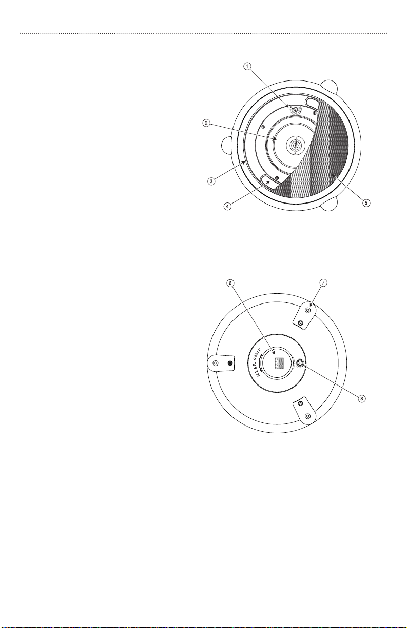
Product Diagrams
OPS1 Front Drawing
1.Tap Selection Switch
2. Coaxial Driver Assembly
3. Grille Retention Slot
4. Bass Tuning Vent (x2)
5. Perforated Steel Grille
OPS1 Rear Drawing
6. Snap-Lock Input Connector
7. Suspension Points (x3)
OPS1 Front Drawing
(grille partially shown)
8. Safety Cable Suspension Point
Package Contents
(1) Orbit Pendant Speaker
(1) Snap-Lock Input Connector
(1) Quick-Snap Clip
(3) Suspension Cables with Forged Eyebolts
(3) Nuts (may be installed onto eyebolts)
(1) Installation and Use Manual
OPS1 Rear Drawing
1
Page 4

Selecting Power Level
Select the power level using the front-mounted selector switch. The speaker grille
must be removed prior to selecting the power level. See Speaker Grille Installation &
Removal section for proper grille removal procedures.
Selecting Power Level
The front-mounted selector switch is used to set the
appropriate power level or impedance for your
system. Using a small flat-blade screwdriver, turn the
knob until the slot points to the power level you
require.
70V/100V Systems
Both power setting scales for 70V and 100V systems
are labeled on the speakers. On the 100V scale, the
last position clockwise is marked with a (not avail-
able) symbol. Do not use this position in 100V
systems.
ΩΩ
16
Systems
The fully counterclockwise position of the setting switch is the 16-ohm position.This
setting is suitable for use with low-impedance amplifiers that typically support 4- or
8-ohm speakers.The speaker’s higher, 16-ohm impedance makes it easier to combine
multiple speakers into series-parallel networks while keeping the total system
impedance at a level suitable for low-impedance amplifiers.
Speaker Grille Installation & Removal
Installation
The speaker grille fits tightly! Make sure the tap settings are correct prior to re-installing grille. Push the
speaker grille in until it can go no further. Then, slap
around the edge of the grille to seat the grille. The
grille is properly seated when it is flush with the edge
of the bezel.
Removal
Insert a pocketknife blade between the grille and the
bezel about a
upwards. Do this in multiple places around the
circumference of the grille to free the grille.
1
/4" deep and then gently pry the grille
2
Page 5
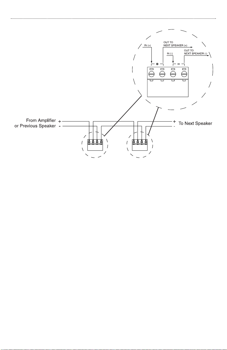
Speaker Wiring
Wiring is terminated at a snap-lock input
connector. There are two positive and two
negative terminals to accommodate daisychaining of speakers in a system. All wiring
should be done prior to installation and then
plugged into the rear of the OPS1.
Daisy-Chaining
The OPS1’s snap-lock input connector allows
for easy daisy-chaining of speakers by providing
a second terminal of each polarity. Refer to the
figures for proper wiring for daisy-chaining of
terminals.
Speaker Phasing
Keep the same polarity terminals wired together to ensure correct phasing. In order
to provide the best possible sound, all of the speakers in a system need to be pushing out and pulling in at the same time.
If the connections to one speaker in a system are reversed from the others, that
speaker’s movement will be out of sync with the other speakers.This will result in a
loss of low frequency response and will effect the overall performance of the
system.
3
Page 6

Speaker Installation
Suspension Cable Assembly
1. Screw nuts onto the three (3) eyebolts all the
way to the flange.
2. Screw in eyebolts with captured cable
sections into the three (3) suspension points.
Do not overtighten.
3. Snap the loops of the three (3) free ends of
the cable sections into the quick-snap clip.
4. Connect the quick-snap clip to the drop cable
loop (not included).
Safety Cable (not included)
The speaker includes a safety cable suspension
point for extra protection. Refer to instructions
with cable kits for proper use.
IMPORTANT
The anchor point and any hardware used
to anchor the speaker must be able to
support the speaker’s weight under all
conditions. IF YOU ARE NOT SURE OF
THE PROPER CAPACITY OF THESE
ITEMS TO USE, CONSULT A STRUCTURAL ENGINEER. Mount only one speaker
per supplied quick-snap clip.
1.
2.
3.
4.
Accessory
CK10 (Cable Kit, 10')
The CK10 is a 10-foot cable with one looped end, a forged eyebolt (with 1/4-20" x
1/2" thread), and an adjustable cable clamp. It is suitable for use as a drop cable or
safety cable.The CK10 is available in black, white, or silver.
4
Page 7

Specifications
SPECIFICATIONS
Frequency Response (-10 dB)
LF Driver
HF Driver 20 mm (3/4
*
6-1/
(MLS Voice Coil Centering System)
OPS1
60 Hz to 19 kHz
2" MDT Metal-Alloy Cone
") Polycarbonate Dome
Sensitivity (1W/1m) 89.5 dBspl (Average 100 Hz - 10 kHz)
Dispersion
Impedance Ratings
Power Input (Max.)
Power Settings (in watts)
Low (16 ohms) / High (70V/100V)
100W @ 16 ohms; 32W @ 70V/100V
†
70V: 32, 16, 8, 4, 2, 1W
100V: 32, 16, 8, 4, 2W
120°
Enclosure Material Fire-rated (94VO) ABS
Grille Material Powder-Coated Perforated Metal
Terminations 4 Terminal Snap-Lock Input Connector
Product Weight
Speaker Dimensions
Included Accessories
Optional Accessories
(1) Quick-Snap Clip; (1) Snap-Lock Input Connector;
(3) Suspension Cables with Forged Eye Bolts; (3) Nuts
10 lb.
15" dia. x 9-
1
/4" D
Cable Kit (CK10)
Enclosure Finish & Color Textured White or Black
Listings CSA/UL Listed
*
Free Space Response, 16-ohm input
† Front panel, switch-selected.
5
Page 8

Limited Warranty
The Orbit Pendant Speaker, model OPS1, is warranted to be free from defects in material or workmanship for five (5) years from the date of sale to the original purchaser. Any
part of the product covered by this warranty that, with normal installation and use,
becomes defective will be repaired or replaced by Bogen, at our option, provided the
product is shipped insured and prepaid to: Bogen Factory Service Department, 50
Spring Street, Ramsey, NJ 07446, USA. The product will be returned to you freight prepaid. This warranty does not extend to any of our products that have been subjected to
abuse, misuse, improper storage, neglect, accident, improper installation or have been
modified or repaired or altered in any manner whatsoever , or where the serial number or
date code has been removed or defaced.
THE FOREGOING LIMITED WARRANTYIS BOGEN’S SOLE AND EXCLUSIVE WARRANTY AND THE PURCHASER’S SOLE AND EXCLUSIVE REMEDY. BOGEN
MAKES NO OTHER WARRANTIES OF ANY KIND, EITHER EXPRESS OR IMPLIED,
AND ALL IMPLIED WARRANTIES OF MERCHANTABILITY OR FITNESS FOR A
PARTICULAR PURPOSE ARE HEREBY DISCLAIMED AND EXCLUDED TO THE
MAXIMUM EXTENT ALLOWABLE BY LAW. Bogen's liability arising out of the manu-
facture, sale or supplying of products or their use or disposition, whether based upon
warranty, contract, tort or otherwise, shall be limited to the price of the product. In no
event shall Bogen be liable for special, incidental or consequential damages (including,
but not limited to, loss of profits, loss of data or loss of use damages) arising out of the
manufacture, sale or supplying of products, even if Bogen has been advised of the possibility of such damages or losses. Some States do not allow the exclusion or limitation
of incidental or consequential damages, so the above limitation or exclusion may not
apply to you. This warranty gives you specific legal rights, and you may also have other
rights which vary from State to State.
Products that are out of warranty will also be repaired by the Bogen Factory Service
Department -- same address as above or call 201-934-8500. The parts and labor
involved in these repairs are warranted for 90 days when repaired by the Bogen Factory
Service Department. All shipping charges in addition to parts and labor charges will be
at the owner's expense. All returns require a Return Authorization number.
50 Spring Street, Ramsey, NJ 07446, U.S.A.
Tel. 201-934-8500, Fax: 201-934-9832, www.bogen.com
 Loading...