

Page 1

NQ-S1810WT-G2
Nyquist Gen-2 VoIP
Wall Bae Speaker
Installation
©2020 Bogen Communications, Inc.
Specications are subject to change.
740-00124-00B 2006
Page 2

NQ-S1810WT-G2
Nyquist Gen-2 VoIP
Wall Bae Speaker
Installation Manual
With the Nyquist Series Gen-2 VoIP Wall Bae Speaker, there is no need
for external ampliers, traditional intercom wiring, or transformer taps to
manually set or adjust. Connect the speaker via Cat5 to a Power-Over-Ethernet (PoE) Switch or PoE Injector, and it is ready to use.
The speaker features an integrated 10 watt power amplier, a CAN
Bus interface, a MEMS digital microphone for superior talkback audio,
and a Form C SPDT type 2-amp dry contact relay for controlling/overriding third-party devices like AV sources.
The speaker also allows DHCP deployment for easy installation. You can
let your Nyquist server automatically discover and congure your speaker,
or you can manually congure it through the speaker’s web-based
user interface (web UI). The web UI also allows easy updating of
rmware and setting of parameters for Digital Signal Processing (DSP).
For more information about the web UI, refer to the Nyquist Gen-2 VoIP
Speakers Conguration Manual.
Page 3
Speaker Layout
The layout of the speakers should be planned prior to installation.
Because wall bae speakers are designed to project forward, it is best to
aim them in the same direction as this provides for both greater coverage
and clarity. You can use the building’s roof pillars or other available sup-
ports for mounting the wall baes.
In some cases, it may be necessary to mount the wall baes on opposing walls. In these cases, the speakers will project sound in opposing
directions.
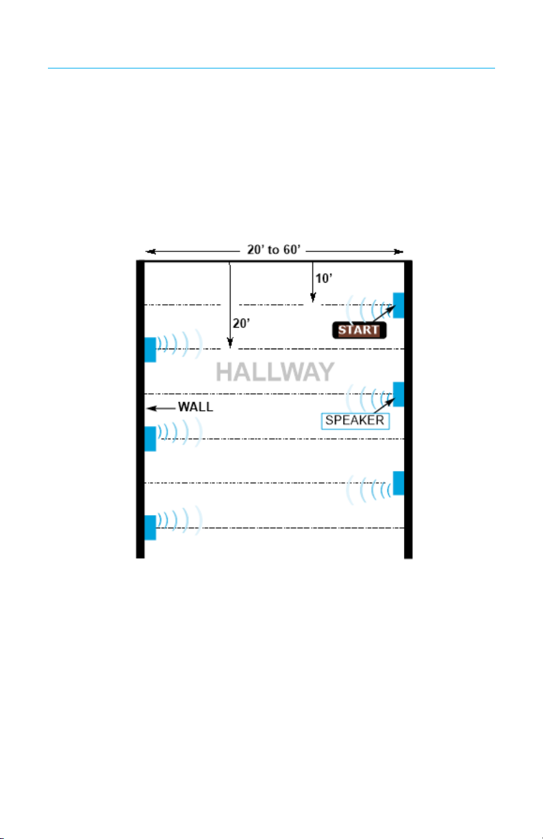
Figure 1
HALLWAY - Wall bae speakers work well with rooms and hallways that
are 20’ to 60’ wide. Layout starts at one end of the hallway or room. The
rst speaker should be installed 10’ from the end of the hallway or room.
The next speaker on that wall should be installed 20’ from the rst speaker. Each additional speaker should be installed 20’ apart from the previous one. The rst speaker on the opposing wall should be installed 20’
from the end of the hallway or room, thereby staggering the speakers.
Each additional speaker should be installed 20’ apart from the previous
one (see Figure 1).
Page 4

Speaker Layout (cont’d)
Figure 2
ROOMS - In most cases, an environment, such as a classroom,
requires only a single wall bae speaker to service the entire room. The
nal placement of the speaker within the room can vary, but common
area locations such as at the head of the room or near the room entrance
aretypically chosen (see Figure 2). Based on the speaker position that
has been selected, you can choose between several mounting options
(see Figures 3-6).
Speaker Installation
Step 1
Select the mounting option from Figures 3–6 and use the appropriate
hardware for gang box mount or wall mount. Bogen provides the screws
and the washers for mounting on a standard electrical gang box, but
when mounting directly to a wall or other surface, you must supply the
appropriate hardware for the specic wall/surface construction type
(for example, concrete cinder block, metal beams etc.).
NOTE: Wall baffle speakers should be installed at a height of between 8 and
16 feet from the floor depending upon need.
2X2 Wall Mount Box Mount
Figure 3
Figure 4
Side
View
Page 5

Speaker Installation (cont’d)
Corner Mount
Figure 5
Tilt Mount
Figure 6
Side
View
Step 2
When applicable, use the pluggable CAN bus connector to attach one
or more NQ-E7020 Digital Call Switch to the Nyquist VoIP Full Duplex
Module 820-00071-00 as shown in Figure 7.
Figure 7
NQ-E7020 Digital
Call Switch
Step 3
If the CAN bus is to be used, ensure the CAN_H and CAN_L use (Cat 5
10/100) twisted pair cable.
Step 4
To connect a third-party device to the dry contact relay output, do one
of the following:
a. If the device is looking for a Normally Open contact, connect
the device using the NO and COM terminals.
b. If the device is looking for a Normally Closed contact, connect
the device using the NC and COM terminals
Page 6

Speaker Installation (cont’d)
Step 5
Use Category 5 or higher Ethernet
cable to connect the speaker
(Figure 8). The power is supplied
by PoE using an 802.3af compliant
network switch or PoE injector.
Figure 8
Step 6
To assemble the Wall Bae Speaker (Figure 9), rst align the two notches
(A) located at the top of the speaker bae with the notches (B) at the
top of the rear housing. Then, rotate the speaker bae downward until
the two bottom sections (C & D) snap together.
NOTE: Refer to the Nyquist Gen2 VoIP Speakers Conguration
Figure 9
Manual or the Nyquist System
Administrator Manual for detailed instructions on how to
congure these speakers.
Using the Reset Button
The Reset button (Figure 10) allows you to either reboot the VoIP speaker or to reset the appliance’s conguration settings to the factory default
settings. For more information about resetting conguration settings,
refer to the Nyquist Gen-2 VoIP Speakers Conguration Manual.
Figure 10
Page 7

Compliance
NOTE: This equipment has been tested and found to comply with the
limits for a Class A digital device, pursuant to Part 15 of the FCC rules.
These limits are designed to provide reasonable protection against
harmful interference when the equipment is operated in a commercial
environment. This equipment generates, uses, and can radiate radio
frequency energy and, if not installed and used in accordance with the
instruction manual, may cause harmful interference to radio communications. Operation of this equipment in a residential area is likely to cause
harmful interference; in which case, the user will be required to correct the
interference at his own expense.
Additional Accessories
The Nyquist Gen 2 VoIP Wall Bae Speaker can be used with the
Nyquist Digital Call Switch NQ-E7020. Refer to the Nyquist Digital Call
Switch NQ-E7020 Quick Start Guide..
Page 8

Limited Warranty, Exclusion of Certain Damages
The NQ-S1810WT-G2 is warranted to be free from defects in materials and workmanship for ve (5)
years from the date of sale to the original purchaser. Any part of the product covered by this warranty
that, with normal installation and use, becomes defective (as conrmed by Bogen upon inspection)
during the warranty period will be repaired or replaced by Bogen, at Bogen’s option, with new or refurbished product, provided the product is shipped insured and prepaid to: Bogen Factory Service Department: 4570 Shelby Air Drive, Suite 11, Memphis, TN 38118, USA. Repaired or replacement product(s)
will be returned to you freight prepaid. This warranty does not extend to any of our products that have
been subjected to abuse, misuse, improper storage, neglect, accident, improper installation or have been
modied or repaired or altered in any manner whatsoever, or where the serial number or date code has
been removed or defaced.
THE FOREGOING LIMITED WARRANTY IS BOGEN’S SOLE AND EXCLUSIVE WARRANTY AND THE PURCHASER’S SOLE AND EXCLUSIVE REMEDY. BOGEN MAKES NO OTHER WARRANTIES OF ANY KIND,
EITHER EXPRESS OR IMPLIED, AND ALL IMPLIED WARRANTIES OF MERCHANTABILITY OR FITNESS
FOR A PARTICULAR PURPOSE ARE HEREBY DISCLAIMED AND EXCLUDED TO THE MAXIMUM EXTENT
ALLOWABLE BY LAW. Bogen’s liability arising out of the manufacture, sale or supplying of products or
their use or disposition, whether based upon warranty, contract, tort or otherwise, shall be limited to the
price of the product. IN NO EVENT SHALL BOGEN BE LIABLE FOR SPECIAL, INCIDENTAL OR CONSE-
QUENTIAL DAMAGES (INCLUDING, BUT NOT LIMITED TO, LOSS OF PROFITS, LOSS OF DATA OR LOSS
OF USE DAMAGES) ARISING OUT OF THE MANUFACTURE, SALE OR SUPPLYING OF PRODUCTS, EVEN
IF BOGEN HAS BEEN ADVISED OF THE POSSIBILITY OF SUCH DAMAGES OR LOSSES. Some States do
not allow the exclusion or limitation of incidental or consequential damages, so the above limitation or
exclusion may not apply to you. This warranty gives you specic legal rights, and you may also have
other rights which vary from State to State.
Products that are out of warranty will also be repaired by Bogen Factory Service Department -- same
address as above or call 201-934-8500, at owner’s expense. Returned products which do not qualify for
warranty service, may be repaired or replaced at Bogen’s option with a previously repaired or refurbished
items. The parts and labor involved in these repairs are warranted for 90 days when repaired by the
Bogen Factory Service Department. All parts and labor charges as well as shipping charges will be at
the owner’s expense.
All returns require a Return Authorization number. For most ecient warranty or repair service, please
include a description of the failure.
9/2019
www.bogen-ip.com • www.bogenedu.com
 Loading...