

Page 1

MULTICOM 2000
®
Administrative Communications System
Installation Instructions
Specifications subject to change without notice.
© 2005, 2016 Bogen Communications, Inc.
All rights reserved.
54-5910-06F 1604
Page 2
Compliance
Warning: Changes or modifications to this unit not expressly approved by the party responsible for compliance could
void the user’s authority to operate the equipment.
This equipment has been tested and found to comply with the limits for a Class A digital device, pursuant to Part 15 of
the FCC Rules. These limits are designed to provide reasonable protection against harmful interference when the equipment is operated in a commercial environment. This equipment generates, uses, and can radiate radio frequency energy
and, if not installed and used in accordance with the instruction manual, may cause harmful interference to radio communications. Operation of this equipment in a residential area is likely to cause harmful interference in which case the
user will be required to correct the interference at his or her own expense.
This digital apparatus does not exceed the Class A limits for radio noise emissions from digital apparatus set out in the
Radio Interference Regulations of the Canadian Department of Communications.
Le present appareil numerique n’emet pas de bruits radioelectriques depassant les limites applicables aux appareils
numeriques del la class A prescrites dans le Reglement sur le brouillage radioelectrique edicte par le ministere des
Communications du Canada.
Safety
Complies with Standards: ANSI/UL 60950, 3rd Edition and CAN/CSA C22.2 N. 60950-00
CAUTION
ATTENTION
TO REDUCE THE RISK OF FIRE, DO NOT INSTALL THIS
EQUIPMENT ON OR NEAR ANY FLAMMABLE MATERIALS.
Afin de réduire les risques d’incendie, ne pas installer cet
équipement sur ou près de matériaux inflammables.
REFER SERVICING TO QUALIFIED SERVICE
PERSONNEL.
Soumettre l’entretien au personnel de maintenance qualifié.
WHEN SERVICING MULTICOM, BE SURE TO REMOVE
AC POWER ON ALL THE POWER SUPPLIES,
THE MC512A, AND ALL MC2626B.
Lors de l’entretien de MULTICOM, assurez vous de couper
le secteur de toutes les alimentations, le MC512A et tous
les MC2626B.
TURN OFF AC POWER SWITCH ON POWER STRIP
OR DISCONNECT MAIN AC POWER CORDS PRIOR
TO SERVICING.
Utiliser le bouton de la multiprise électrique pour l’éteindre,
ou débrancher les cables secteur avant tout entretien.
RISK OF EXPLOSION IF BATTERY IS REPLACED BY AN
INCORRECT TYPE. DISPOSE OF USED BATTERIES
ACCORDING TO THE INSTRUCTIONS.
Risque d’explosion si la batterie remplacée est d’un modèle non conforme. Se débarasser des batteries usagées selon les instructions.
REPLACE FUSES WITH ORIGINAL OR EQUIVALENT
TYPE.
Remplacer les fusibles par des modèles d’origine ou de type
équivalent.
THE AC POWER STRIP IS NOT FOR EXTERNAL USE.
La bande de courant alternatif N'est pas pour l'usage externe.
CAUTION
RISK OF ELECTRIC SHOCK
DO NOT OPEN
CAUTION: TO PREVENT THE RISK OF ELECTRIC
SHOCK, DO NOT REMOVE COVER (OR BACK).
NO USER-SERVICEABLE PARTS INSIDE.
DO NOT OPEN. REFER SERVICING TO
QUALIFIED PERSONNEL.
Afin de prévenir tout risque d’électrocution,
ne pas enlever le couvercle (au dos). Aucune
pièce à maintenir ne se trouve à l’intérieur.
Ne pas ouvrir. Soumettre l’entretien au personnel
de maintenance qualifié.
NOTE: Prior to servicing,
power must be removed
from all power supplies.
Page 3

3
Introduction ..................................................................................................4
Configurations ..............................................................................................4
Cabinet-Mounted System Equipment ..........................................................5
Rack-Mounted System Equipment .............................................................7
Multi-Graphic System Equipment ...............................................................7
Wiring and Setup ........................................................................................10
Cabinet System Installation ........................................................................11
System Assembly Installation .....................................................................11
System Wiring Connections ........................................................................12
Rack System Installation .............................................................................14
Station Equipment Installation ....................................................................20
Administrative Station Wiring ......................................................................21
CA21B Call-In/Privacy Switch Wiring ..........................................................21
CA15C Call-In Switch Wiring ......................................................................22
HS201C and HS202C Handset Wiring .......................................................22
Enhanced Staff Station Wiring ....................................................................23
Circuit Cards ...............................................................................................24
Analog Card Adjustment Procedure ...........................................................25
Power Supplies ...........................................................................................26
Telephone Station .......................................................................................27
MCAPI2 .......................................................................................................29
Table of Contents
Page 4

4
Introduction
This document provides installation information for Bogen’s Multicom 2000® Administrative Communications system.
It is for use by trained contractor personnel only.
Installation is subject to compliance with local electrical codes and other factors which are determined by local codes
and ordinances. Therefore, some of the installation instructions in this manual are generalized and apply to different
installation environments and not to any one specific installation.
The actual operating software for Multicom 2000 exists in various versions. The software is contained in Read Only
memory on various chips on the processor card. It is important to consult the Applications Engineering Department
of Bogen Communications, when software changes or updates are made. All user-determined program changes are
made via an administrative phone. Instructions for customizing system programming are found in Bogen publication
54-5911-07x. User instructions are contained in Bogen publication 54-5912-06x.
Configurations
The Multicom 2000 system is built around a card frame that accommodates the processor card and station/analog
card pairs. These card pairs are interconnected to each other and to a respective relay card through the card frame
back plane. It is available factory assembled in three configurations:
Cabinet-Mounted
The cabinet-mounted system uses the MCMF card frame and MCRC relay cards. It holds one processor card and
one station/analog card pair for each 24 stations. The cabinet system is designed for smaller installations where station capacity will not exceed 120 stations (or 96 stations plus up to 8 “telco” stations when using Model MCTC telephone option card). The cabinet-mounted system includes the audio program interface and all necessary power supplies in a heavy gauge steel cabinet (semi-recessed or surface wall-mounted) cabinet.
(See Figures 1 and 2)
.
Rack-Mounted
The rack-mounted system uses the MCRMF card frame and the MCRM relay module. The MCRMF card frame has
an extra slot not found in the cabinet-mounted frame and provides capacity of up to 120 stations, plus the added
capacity of 8 “telco” stations (when telephone option card is included). Two card frames can be linked together to
accommodate as many as 240 stations (and as many as 15 “telco” stations).
Rack-Mounted with Bogen Multi-Graphic
®
equipment
The station capacity of the Multicom 2000 system is the same as the rack-mounted systems described above. The
Multi-Graphic equipment provides redundant system capabilities, additional program channels (up to 2), custom
emergency-page capabilities, high-power amplification, control of satellite systems, and control of Multi-Graphic system functions
(See Figure 3)
.
Page 5
5
Cabinet-Mounted System Equipment
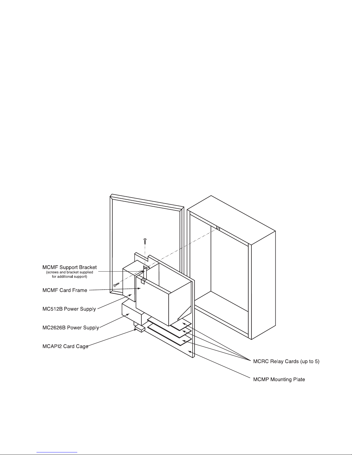
MCBBC Back Box Assembly, Complete
MCMP Mounting Plate with the following components:
MCMF Mainframe assembly with the following circuit cards:
MCPCA3 Processor Card (1 per system)
MCACB Analog Card (1 per 24 stations)
MCSC Station Card (1 per 24 stations)
MC512B Power Supply (1 per system) ± 5/12V DC
MC2626B Power Supply (1 per system) ± 26V DC analog board only
MCAPI2 Audio Program Interface Assembly (911 Special Operation)
MCRC Relay Card (1 per 24 stations)
MCCA Ribbon Cable Assembly
MCTC Optional Telco Access Card (MCTCA). Occupies one MCSC Station Card slot. Includes MCOC
Connector Card and MCOCA Cable Assembly.
Modules Accepts up to 3 input modules per system. Modules install in the MCAPI2 Assembly and interface
with program sources (microphone, CD Player, tuner, etc.).
Figure 1 - MCBBC Assembly
Page 6
6
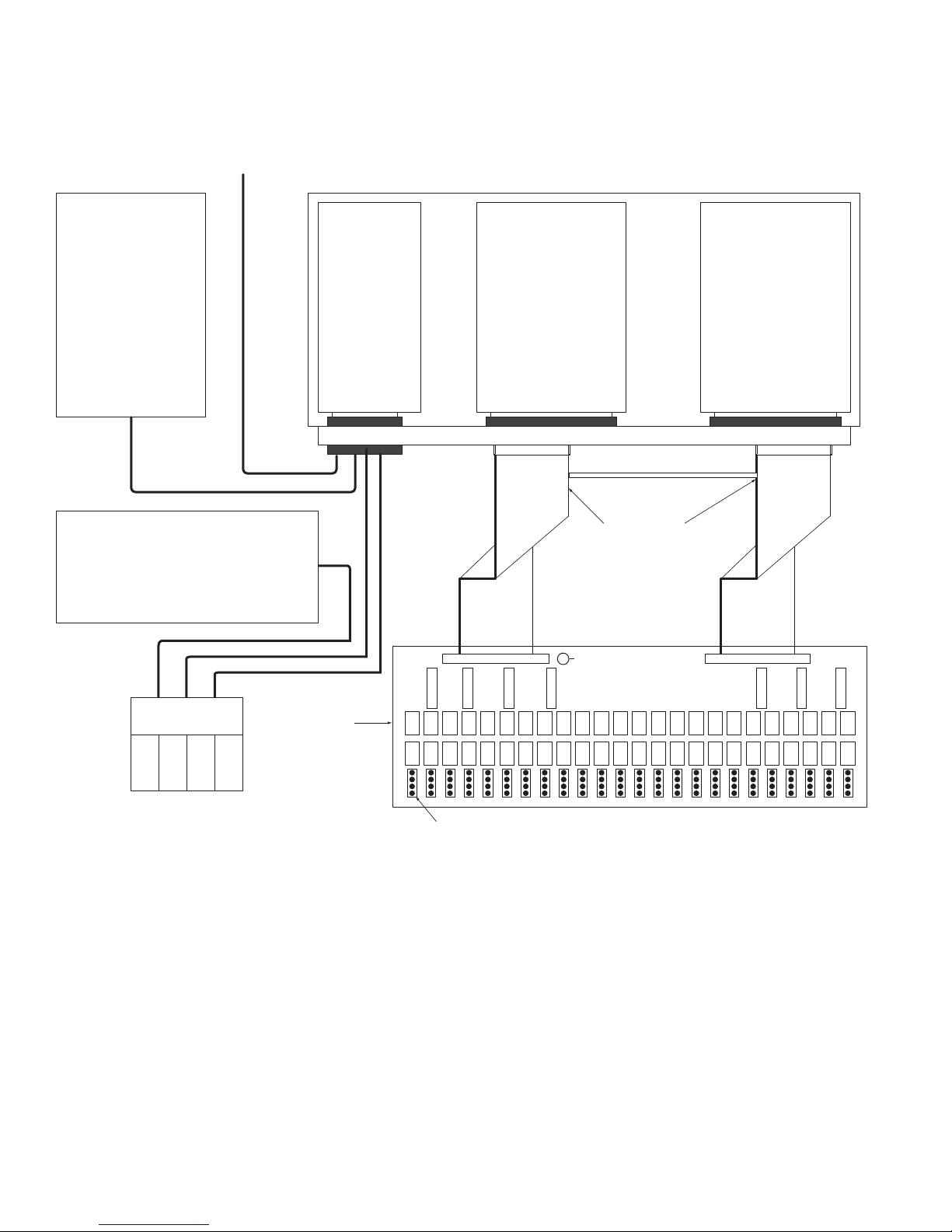
Figure 2 - Multicom 2000, Cabinet-Mounted Configuration
Relay Driver Circuits;
RS-232, RS-485 Serial Ports;
Additional Field Wiring
MC512B
Power Supply
Power Supply
MCAPI2 Audio
Program Interface
MC2626B
MCPCA3
Processor Card
MCRC Relay Card
(Typ. of up to 5)
MCACB
Analog Card
MCMF Wall-mounted Main Frame & Back Plane
MCCA Ribbon
Cable Assembly
MCSC
Station Card
Station terminations - 24 groups of 4 pins
Page 7

7
Rack-Mounted System Equipment
TCPER42 Equipment Rack, 42" High (Contains 24 1-3/4" rack spaces)
TCPER61 Equipment Rack, 61" High (Contains 35 1-3/4" rack spaces)
TCPER77 Equipment Rack, 77" High (Contains 44 1-3/4" rack spaces)
MCRMP Rack-Mounting Panel with the following components:
MC512B ± 5/12V DC Power Supply (1 per system)
MC2626B ± 26V DC Power Supply (1 for up to 120 stations, 2 for 121 stations or more)
MCAPI2 Audio Program Module Interface Assembly (1 per system)
MCRMF Rack-Mounting Mainframe (1 per 120 stations)
Includes built-in ventilation fans and the following circuit cards:
MCPCA3 Processor Card (1 per MCRMF)
MCACB Analog Card (1 per 24 stations)
MCSC Station Card (1 per 24 stations)
MCJCA Ribbon Cable Assembly interconnects 2 mainframes
MCRM Relay Module (1 per 24 stations). MCRM is mounted as MCRRP in stand-alone system,
or SBA225 Switchbank in systems incorporating Bogen Multi-Graphic Equipment.
MCRC Relay Card (1 per 24 stations)
MCRCA Ribbon Cable Assemblies
MCTC Optional Telco Access Card (1 per MCRMF). Includes:
MCTCA Telco Card
MCOC Connector Card
MCOCA Cable Assembly
Modules Up to 4 input modules per system. Modules install in MCAPI2 Assembly and interface with program
sources (microphone, CD player, tuner, etc.).
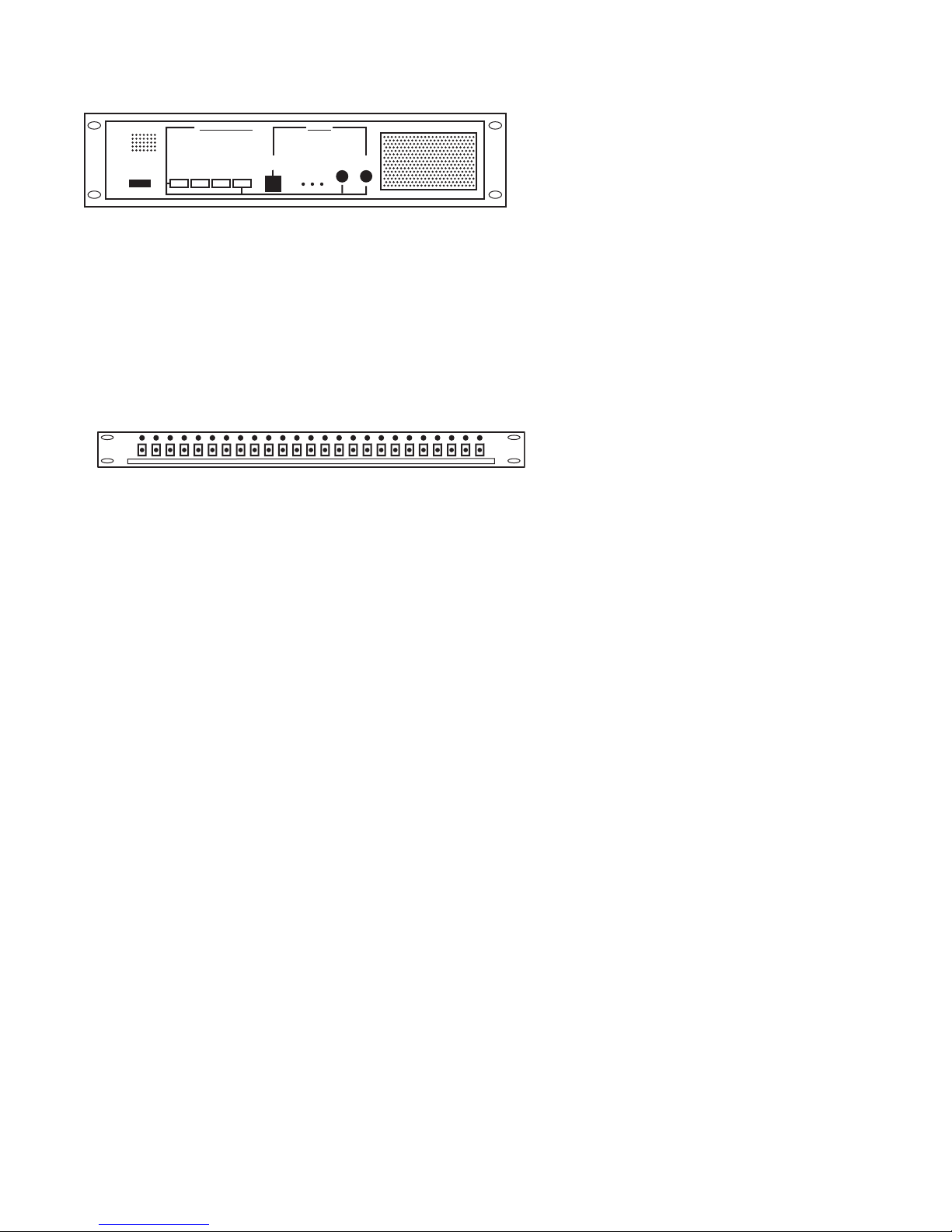
Multi-Graphic System Equipment
MCP35A Master Control Panel
SBA225 Switchbank for use in 2223-Series Systems (25 3-position lever-action switches)
General Equipment
Amplifiers BPA60/HTA125A/HTA250A, as required by system capacity
Program
Sources CD Player with AM/FM Receiver; Multi-Disc CD Player
Page 8
8
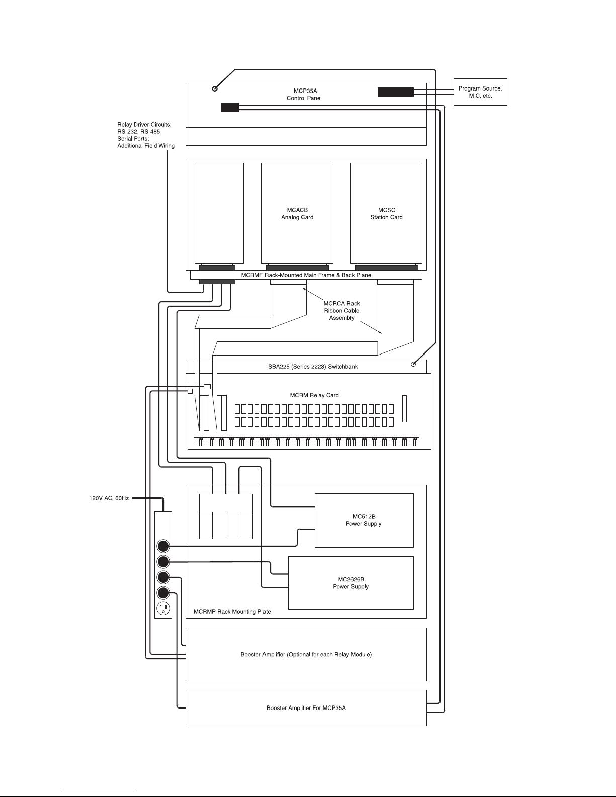
Figure 3. Multicom 2000 with Multi-Graphic Equipment
MCPCA3
Processor Card
25 24 23 22 21 20 19 18 17 16 15 14 13 12 11 10 9 8 7 6 5 4 3 2 1
MCAPI2 Audio
Program Interface
Page 9
The MCPB Control Panel is used with Multicom 2000/Multi-Graphic Series 2233 Systems. It provides
push-button selection of two microphones and one auxiliary program source, a (“B”) program channel
(with level control), and a monitor capability which permits listening to the “A” or “B” program over
the monitor speaker of the MCP35A. For detailed information on the MCPB panel, refer to Bogen
Publication No. 54-5875-xx.
9
The MCP35A Master Control Panel is used in Multicom 2000/Multi-Graphic Series 2223 & 2233 Systems.
It provides push-button selection of two microphones and one auxiliary program source, an additional
(“A”) program channel (with level control), an intercom channel, monitoring capability, and emergency
call capability. For detailed information on the MCP35A, refer to Bogen Publication No. 54-5871-xx.
MCP35A Control Panel
Switchbank
SBA225
The SBA225 Switchbank is used in Multicom 2000/Multi-Graphic 2223 System, respectively. The MCRM relay
modules connect directly to the switchbanks and provide the interface between a Multi-Graphic and a Multicom
2000 System. The SBA225 has 25 3-position lever-action switches to select the “A” program channel, Intercom
channel, or Off.
Note: The 25th switch on each switchbank is reserved for Multi-Graphic use.
Figure 4 - MCP35A
Figure 6 - Switchbank
CONSOLE MIC
EMERGENCY PAGE
PROGRAM DISTRIBUTION
MIC 1 MIC 2 AUX
ROOMS
ALL
PRESS TO TALK
RELEASE TO LISTEN
INTERCOM
PROGRAM/
TALK LEVEL
N P O
PROGRAM
MONITOR-
LISTEN
Page 10
10
Wiring and Setup
Location Planning
Both wall- and rack-mounting versions of Multicom 2000 should be located centrally to the rooms to be served to
minimize the length of cable runs. Consider the following requirements when choosing a location.
• The location should be well ventilated and dry. Avoid rain or moisture or areas likely to be exposed to these hazards.
• Do not locate the system near heat-generating sources such as direct sunlight, radiators, or warm air ducts.
• There should be enough room to open the door of the cabinet mounting system. In the case of a rack installation,
there should be sufficient access to the rack door or enough room to move the rack to gain access.
• Where possible, do not locate it in a carpeted room, especially one where a lot of static is present. If this is not
possible, the installation of an antistatic mat below the control center is required.
Wiring Requirements
Class II wiring may be used for station wiring. Support wiring to prevent strain or sagging. Knockouts are provided
on the wall-mounting enclosure or rack to admit wiring.
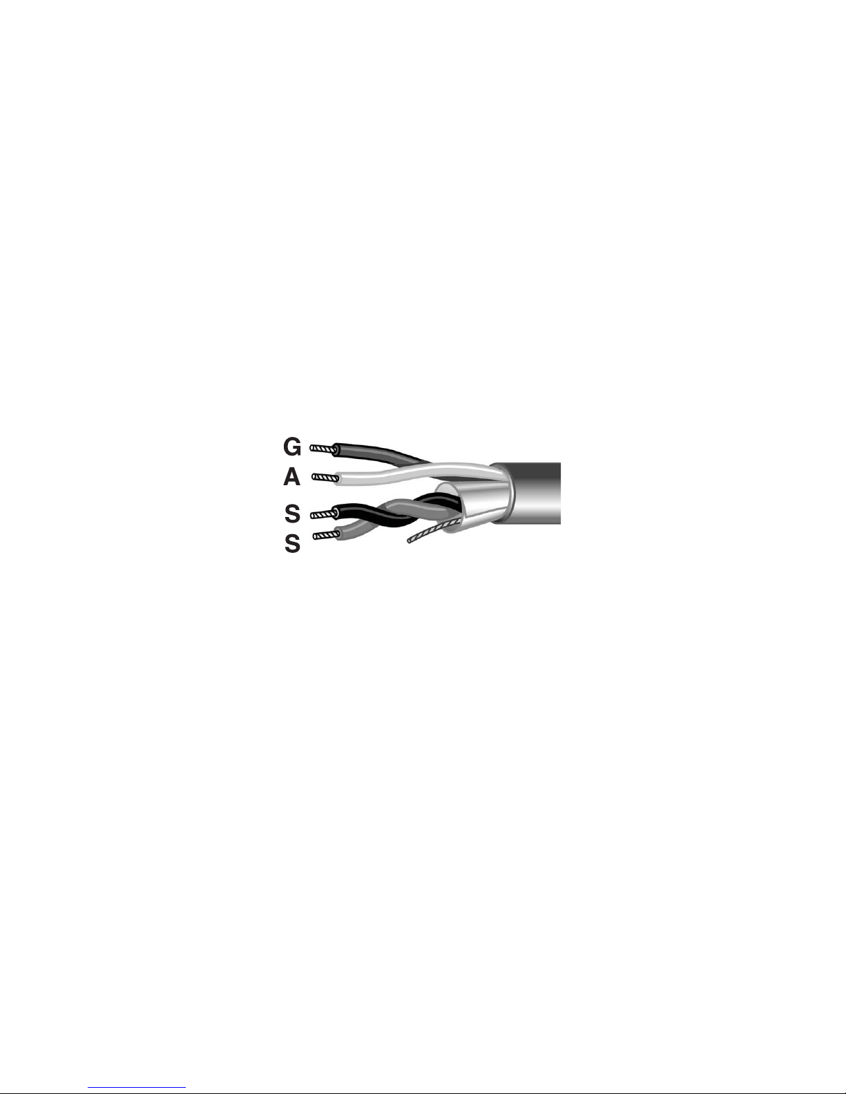
All stations use the same type one pair shielded 100% coverage of aluminum polyester foil with drain wire and one
unshielded pair, such as West Penn #357 or Belden #8724.
(See Figure 7)
.
The cable from each station must be terminated to Bogen connectors (2518, 2520, 2522), which are then connected
to the interface pins on the relay card or module. Failure to use the proper connectors, recommended wire type, or
use of solder to terminate the cable to the relay card pins will void the warranty.
Installation Precautions
The following precautions are mandatory when installing the Multicom 2000, or when making changes to the equipment and wiring after the initial installation.
• Disconnect all 120V AC power sources before making any changes in system equipment or wiring.
• Wear a properly grounded conductive wrist strap when working at the control center or at any staff
station where the wiring for the staff station is connected to equipment at the control center.
• Use care when running wire from the station equipment to the control center. Keep all wiring well
isolated from 120V AC (and higher) power lines.
NOTE: Use grommet edging material to prevent abrasion against sharp edges of knockouts of rack.
Figure 7
Page 11

11
Cabinet System Installation
Wall Unit AC Box Connection
Supply 120V AC power to the unit through conduit, BX or Romex
in accordance with local electrical codes.
Protective Earth Terminal must be secured in place with star washer and nut assembly.
(See Figure 8).
First connect 120V AC Green ground wire on protective earth terminal and secure with star washer and nut assembly.
Next connect three GREEN/YELLOW grounding wires and secure
with star washer and nut assembly.
Connect the remaining two 120V AC wires using twist type wire
nuts. Add a second securement means such as heatshrink tubing or
electrical tape.
Install the junction box into the back box and secure with 4 #6-32
x 3/8 screws and keep nuts (surface-mount) or 4 #6 x 3/8 screws
(recessed-mounted).
Surface-Mounted
Install the back box on the wall, making sure that the box is
squarely mounted. Allow access above box for 120V AC wiring.
Remove knockouts from bottom or rear panels, as desired, to
admit station wiring.
Bring 120V AC power to the upper left-hand corner of the box.
Secure the back box to the wall with screws through keyhole slots
and back holes (16" on center).
Recessed-Mounted
Prepare mounting hole for back box. Hole size should be 24" W x
32" H x 4" D minimum opening with studs or mounting surfaces on
each side. The back box is designed to be recessed approximately
4 inches. Remove knockouts from bottom or rear panels, as
desired, to admit station wiring.
Bring 120V AC power to the upper left-hand corner of the box.
Install the back box into the wall, making sure that it is squarely
mounted. Secure the box to the mounting surfaces with screws
through holes in side panels (2 per side, 2" from rear panel).
Attach trim ships (MCTS) to outside panels and finished wall.
System Assembly Installation
Make sure Tinnerman clips are installed on tabs on the lower part of back panel of box.
Lift the system assembly panel (hold by power supply and main card cage) and insert into box. Mount the panel to the
box by engaging the lip on top of the panel with tabs in the upper part of back panel of box as shown in Figure 8.
Secure the panel to the box with screws through Tinnerman clips, as shown.
Figure 8 - AC Box Connection
Page 12

12
System Wiring Connections
Power Supplies & Relay Card
The AC power cord from the MC512B power supply is plugged into the AC surge protector power strip on the cabinet. The power cord from the MC2626B power supply is also plugged into the same power strip.
(See Figure 9)
.
Power supply output wiring is grouped into cables, each ending with a keyed connector. Two of the cables from the
MC512A are connected to P3 and P2 on the card frame back plane. The cable from the MC2626B is connected to
J6 on the MCAPI2 and from the MCAPI2 to P1 back plane.
The MCRC relay card is used only in the cabinet-mounted version of the Multicom 2000 System. The card contains
24 (each) program and intercom relays and 24 sets of terminals (4 pins per set) for connection with station wiring.
Station numbers are assigned to the MCRC relay card in ascending order, from left to right.
Each station/analog card pair connects to a corresponding relay card via the card frame back plane “J” connectors,
using two ribbon cables (MCCA ribbon cable assembly). The 36" long cable connects to the analog card “J”
connector (on the back plane) to connector J26 on the relay card. The 30" long cable connects to the station card
“J” connector (on back plane) to connector J25 on the relay card.
Figure 9 - System Wiring
Station 1
Numbers increase
from left to right
NOTE 1: The cable connector must be
positioned as shown in this detail. It does
not cover all pins – eight pins towards the
center of the back plane are left exposed.
The back plane screening indicates the
correct position of the connector. The flat
cable’s striped (red) conductor must be
on the side with the exposed pins.
Page 13

13
Audio Program Interface
The MCAPI2 audio program interface is connected to P6 on the back
plane. Up to (4) four input modules can be installed in the MCAPI2.
The modules slide into the MCAPI2 and plug into an edge connector
as shown in Figure 10.
Card Frame/Circuit Card Installation
The MCMF card frame used in the cabinet-mounted system includes
a swivel mount to make it easy to install circuit cards. Turn the knob
on one end of the card frame to release the mount and tilt the frame
towards you.
Install the circuit cards in the order shown below. Slide the card into the frame to engage the edge connectors.
Align the locking tabs so that they close when the card is pressed into the connectors. Be sure that each card
is properly seated in the card edge connectors.
The cards will only fit one way!
Refer to the “Telephone Access Card” section on page 27 of this manual for instructions relating to telephone
circuit card installation and connections.
Station Wiring
Knockouts are provided to admit station wiring. Station wiring is described is detail in the Station Equipment
Installation section of this manual.
Other Back Plane Connections
Connectors are provided on the back plane to accommodate some of the options available to Multicom 2000 (relay
driver circuits, external clock control, serial port, etc.). These connections are described in “Other Back Plane
Connections” in the Rack-System Installation section of this manual.
Mounting panel side
Figure 10 - MCAPI2 Installation
Figure 11 - MCMF Card Frame, Top View
Slot # Part No. Type of Card Station #'s
1
MCPCA3 Processor Card
2
3
MCACB
MCSC
Analog Card
Station Card
001 - 024
4
5
MCACB
MCSC
Analog Card
Station Card
025 - 048
6
7
MCACB
MCSC
Analog Card
Station Card
049 - 072
8
9
MCACB
MCSC
Analog Card
Station Card
073 - 096
10
11
MCACB
MCSC
or MCTC
Analog Card
Station Card
Telephone Card
097 - 120
097 - 104
Page 14

14
Rack System Installation
Location and Power Guidelines
Follow the guidelines in the Wiring and Setup section of this manual when choosing a location for the rack.
When choosing a location, consider that if the rear panel of the rack is not accessible, there must be enough space
to move the rack to gain access. Also provide enough cable slack so that station wiring does not interfere with the
ability to move the rack.
Knockouts are provided in the rack to admit station cabling. Support all cables to prevent sagging or strain.
Power Supplies
The rack system uses the MC512B and MC2626B power supplies. These supplies, and the API audio program
interface, are mounted to the MCRMP panel which is itself mounted to the rack. For systems with more than
120 stations, a second MC2626B power supply must be mounted.
The MC512B and MC2626B power cords are plugged into a surge suppressor/power strip.
Auxiliary equipment (power amplifier, Multi-Graphic equipment, etc.) may be plugged into the ACFDS. The ACFDS,
and any auxiliary equipment not plugged directly into the ACFDS, must be plugged into a properly grounded threewire outlet or connected directly to AC by a qualified electrician.
Relay Modules & Ribbon Cable
The MCRM relay module is used only in the rack-mounted system. The module contains (24 each) program and
intercom relays and 24 sets of terminals (4 pins per set) for connection with Multicom 2000 station wiring.
Relay modules are mounted to the MCRRP rack panel, or to SBA-series switchbanks when used with Multi-Graphic
equipment. One relay module is required for each analog/station card pair installed.
Each analog/station card pair connects to the corresponding relay module via the card frame back plane “J” connectors,
using two ribbon cables (model MCRCA ribbon cable assembly). Connect one end of a cable to the analog card “J”
connector (on the back plane) and the other end to connector J26 on the relay module. Connect one end of the other
cable to the station card “J” connector (on the back plane) and the other end to connector J25 on the relay module.
The relay module can handle a maximum of 250 watts of power (or 10 watts per station); connection for a booster
amplifier is provided at RCA 1 & J39. J41 & J42 connect to the back plane of the MCRMF with MCRCA ribbon
cable assemblies. The module also has connectors to interface with an SBA-Series switchbank, emergency contacts
from the MCP35A Master Control Panel, and auxiliary call-in switches. An accessory connector (J40) provides relay
driver capability whenever a station relay goes active (refer to Figure 13 and notes). Station numbers are assigned
to the MCRRP relay card in ascending order from the right to left, skipping the “V” pin (see Note 4).
Page 15

15
25 24 23 22 21 20 19 18 17 16 15 14 13 12 11 10 9 8 7 6 5 4 3 2 1
Note 1: When an external booster amplifier is used, remove jumpers JMP2 & JMP3. Each Relay Module must use
a separate booster amplifier.
Note 2: If using this option with one MCRM module, connect P28 “output” and “return” to MCP35A N.C. contacts
and remove JMP1. If this option is used with multiple relay modules, parallel the “output” and “return” wires
on P28 to each relay module and remove JMP1 on each module.
Note 3: Only the first 24 stations and PR23 & PR24 can be used by the Multicom 2000.
Note 4: The “V” pin is provided for special applications and is not used in typical station installations ("V" pin
is omitted on Rev B versions and higher). It is only on the first station and is furthermost to the right.
DO NOT connect any station to this pin.
Figure 12 - Relay Modules
Page 16

16
Connector J40
Connector J40 provides relay driver outputs for each station which goes active whenever the program or intercom
relay for that station goes active. The pin-outs for J40 are shown in Figure 13. By cutting the proper diode, the output can be made to go active when one or the other relays activate. Refer to Figure 13 and the following example: If
Diode D49 (near program Relay K1) is removed, the output S1RY (on the J40 connector) will go active only when
relay K25 (intercom) is activated. Conversely, if diode D73 (near intercom relay K25) is removed, the output S1RY
will go active only when relay K1 (program) is activated.
Optional circuitry is available at the J40 accessory which can be used to control external bells or other external
devices. Contact Bogen Application Engineering for assistance.
Station 1, Pin 1 N/C
N/C
N/C
N/C
N/C
N/C
N/C
PIN 16, GND
PIN 18, GND
PIN 20, GND
N/C
N/C
N/C
N/C
Station 24, Pin 30
Station 23, Pin 32
Station 22, Pin 34
Station 21, Pin 36
Station 20, Pin 38
Station 19, Pin 40
Station 2, Pin 3
Station 3, Pin 5
Station 4, Pin 7
Station 5, Pin 9
Station 6, Pin 11
Station 7, Pin 13
Station 8, Pin 15
N/C
N/C
Station 18, Pin 21
Station 17, Pin 23
Station 16, Pin 25
Station 15, Pin 27
Station 14, Pin 29
Station 9, Pin 31
Station 10, Pin 33
Station 11, Pin 35
Station 12, Pin 37
Station 13, Pin 39
J40
Relay Coil
(with 1N
4004 Diode)
( + )
Power Supply
(12V DC)
( - )
Figure 13 - J40 Stations to Pin # Schematic
Page 17

17
Audio Program Interface
The MCAPI2 audio program interface is connected to P6 on the back
plane. Up to (4) four input modules can be installed in the MCAPI2.
The modules slide into the MCAPI2 and plug into an edge connector
as shown in Figure 10.
Card Frame(s) & Circuit Cards
The MCRMF card frame is used in rack-mounted versions of the
Multicom 2000 only. It has 12 card slots, accessible from the front
of the rack. Slot numbers run left to right, 1-12. Each card frame
will support up to 120 stations (5 station/analog card pairs) plus a
telephone access card. Each circuit card plugs into the connectors
on the card frame and is connected to the associated relay module
via the MCRCA ribbon cable assemblies.
Slot # Part No. Type of Card Station #'s
1
MCPCA3 Processor Card
2
3
MCACB
MCSC
Analog Card
Station Card
001 - 024
4
5
MCACB
MCSC
Analog Card
Station Card
025 - 048
6
7
MCACB
MCSC
Analog Card
Station Card
049 - 072
8
9
MCACB
MCSC
Analog Card
Station Card
073 - 096
10
11
MCACB
MCSC
Analog Card
Station Card
097 - 120
12
MCTCA (optional) Telephone Card
241 - 248
Slot # Part No. Type of Card
Station #'s
1
Blank
2
3
MCACB
MCSC
Analog Card
Station Card
121 - 144
4
5
MCACB
MCSC
Analog Card
Station Card
145 - 168
6
7
MCACB
MCSC
Analog Card
Station Card
169 - 192
8
9
MCACB
MCSC
Analog Card
Station Card
193 - 216
10
11
MCACB
MCSC
Analog Card
Station Card
217 - 240
12
MCTCA (optional) Telephone Card
249 - 255
First Card Frame
Second Card Frame in Systems with over 120 Stations
A second card frame is used in rack-mounted systems when capacity exceeds 120 stations; however, only one
processor card is used per system.
The processor card is installed in slot #1 of the upper card frame. A jumper block on the back plane of each card
frame must be placed in the proper position, as shown in Figure 14.
Figure 10 - MCAPI2 Installation
Figure 14 - Card Frames
Page 18

18
Station Wiring
Knockouts are provided to admit station wiring. Station wiring is described is detail in the Station Equipment
Installation section.
Other Back Plane Connections
Connectors are provided on the back plane to accommodate some of the options available to Multicom 2000 (Relay
driver circuits, external clock control, serial port, etc. Figure 16 shows the back plane of the card frame assembly
(typical of MCMF and MCRM). It illustrates the location and designations of the connectors used to wire external
function relay drivers, Master clock, and 911 control inputs, and communication ports (future addition).
P4 External Control Inputs
The terminal labeled CLOCK will reset the system time to 06:00 a.m. when shorted through a dry contact closure
from an external master clock (Bogen Time Systems Master Clocks).
P5 Relay Driver Outputs
Each relay driver output is an open collector output that goes low towards ground when activated. Each output is
activated by a DTMF sequence from an administrative telephone: 9421, 9422, 9423, 9424. Connect the external
relay and power supply (12V DC) between the desired output and one of the ground terminals.
Pin 10 of the P4 connector provides Audio Program Input (MCAPI2) #3 emergency priority page when shorted to pin
1 ground or Pin 2 ground through a customer-supplied contact closure.
Two card frames are interconnected by the MCJCA ribbon cable assemblies, as shown in Figure 15. Note that the
upper ribbon cable connector on both card frames must be installed so that the top four pins on each row of pins
are left exposed. The lower ribbon cable connector on both card frames must be installed so that the bottom four
pins on each row of pins are exposed (disregard the schematic representation of the connector printed on the back
plane when connecting the lower ribbon cable assembly).
Figure 15 - MCJCA Ribbon Cable Assemblies
Page 19

19
Figure 16 - Rack Back Plane External Connections
Page 20

20
Station Equipment Installation
The following is a list of staff station equipment that can be connected to the Multicom 2000.
MCDS4 Administrative Telephone (DTMF dialing with 4-line x 16-character LCD display panel)
MCESS DTMF Dialing, Enhanced Staff Telephone, Desk Mount
MCWESS DTMF Dialing, Enhanced Staff Telephone, Wall-Mounted
CA15C Call-In Switch (Press to Call)
CA21B Call-In Switch (Press to Call/Privacy)
In addition to the telephone/handset at each location, the system is designed so that there can be a ceiling- or wallmounted speaker at each location for the purpose of intercom communication, paging, program material distribution,
and dissemination of time signals and alarm tones.
We recommend the Bogen S86 loudspeaker equipped with the T725 line matching transformer as the speaker of
choice at each station location. This speaker is available mounted to a ceiling grille or enclosed in a wall-mounting
baffle. Figures 17- 21 show wiring diagrams for connection to each type of staff station equipment. In these illustrations,
the transformer is tapped at 1/2 watt. The transformer may be tapped at any desired power level; however,
1/2-watt is the recommended load for each speaker. In any event, make sure that the total load to relay card or
relay module (group of 24 stations) does not exceed 20 watts. Contact our Applications Engineering Department if
the load on a card must exceed 20 watts.
Figure 7 shows the termination of one station’s cable at the relay card or relay module.
Important: Termination of staff station wiring at the control center must be made using Bogen 25-Series
connector kits to maintain warranty coverage.
Attach the conductors to the connector as shown in Figure 7, using the TL156 tool. The connector is then placed
on the corresponding pins on the relay card or relay module.
Figure 7 - Termination of one pair shielded and one unshielded pair to centerline connectors
Page 21

21
Administrative Station Wiring
Administrative stations are wired to the control center through a junction box as shown in
Figure 17
. The administrative
station is equipped with a PRS40C power supply which must be plugged into a 120V, 60Hz wall outlet.
CA21B Call-In/Privacy Switch Wiring
When a station includes the CA21B, the white wire from the CA21B must be connected to the center tap of the
station speaker transformer. The center tap of the transformer depends upon the power tap chosen for the speaker.
To determine the appropriate center tap, determine the power tap of the station speaker and use Figure 18 to determine the color of the wire that is the center tap of the transformer. Connect the white wire of the CA21B to the center
tap. Note the 4-watt power tap does not have a center tap; the privacy feature cannot be used in this case.
Figure 17 - Administrative Station Wiring
Figure 18 - CA21B Wiring
8Ω
70V 25V
BLACK COMMON
BROWN 4W
RED 2W
ORANGE
1W
YELLOW 4W
1/2W
GREEN 2W
1/4W
BLUE
1W 1/8W
VIOLET
1/2W
GREY
1/4W
WHITE
1/8W
Page 22

22
CA15C Call-In Switch Wiring
The CA15C Call-In Switch is designed for use with Bogen Multicom 2000 Systems. The red wire connects to the
unshielded conductor, as shown in Figure 19.
HS201C and HS202C Handset Wiring
The HS201C and HS202C handsets include a mounting plate which contains the switching mechanism and wiring.
The wire jumper on the underside of the printed circuit board (next to the resistor) must be cut when the handset is
used with Multicom systems (see instructions provided with the HS201C/202C handset). Connect the red wire to the
unshielded conductor and the black lead to the cable shield, as shown in Figure 20.
Figure 19 - CA15C Wiring
Figure 20 - Handset Wiring
Page 23

23
Enhanced Staff Station Wiring
Enhanced staff stations are wired to the control center through a junction box as shown in Figure 21.
Figure 21. Enhanced Staff Station Wiring
Page 24

24
Circuit Cards
The following circuit cards (Processor/Station/Analog) can be used in the wall-mounted system and the rack-mounted
system. Circuit cards are mounted in the card frame assembly.
Processor Card (Model MCPCA3)
The processor card is the functional heart of the
Multicom 2000. It contains the microprocessor, DTMF
encoder, memory, and system clock. One card is used
per system regardless of system capacity and is
installed in the first position of the MCMF card frame
(wall-mount) or MCRMF card frame (rack-mount). (In
rack-mount systems with greater than 120 stations,
there are 2 MCRMF card frames. In this case, the
processor card is installed in the first position of the
upper card frame.)
Station Card (Model MCSC)
The station card contains crosspoint switches, DTMF
decoder, and talk battery circuits. The card handles
the telephonic switching between the stations on that
card and the system (one card per 24 stations).
The station card is installed in alternating slots of the
card frame, along with its associated analog card.
The card uses a plug-in slo-blo fuse.
Analog Card (Model MCACB)
The analog card contains a 20-watt program amplifier,
12-watt intercom amplifier, and relay control circuits.
The card handles all program amplification and intercom amplification, and talk back operation for the stations on that card (one card is used for each 24 stations). The analog card is installed in alternate slots of
the card frame, along with its associated station card.
The card uses a plug-in fuse. (Bogen Part No. 940001-31).
Figure 22 - MCPCA3
Figure 23 - MCSC
Figure 24 - MCACB
Page 25

25
Analog Card Adjustment Procedure
The MCACB includes controls to adjust the Program/Page Volume, Compression, Talk Back Level, Switching
Sensitivity, and Switching Delay.
Adjustment instructions for the analog card.
1) Adjustment requires two people – one at a speaker station having the highest background noise level,
and one at a telephone at the circuit card location.
2) Do not use a speaker near the telephone that is being used, as this may make it difficult to adjust properly.
3) In wall-mounted systems, the controls can be reached through the slots in the side of the card frame. In
rack-mounted systems, adjustment requires the use of an extender card (Model MCEC).
4) The adjustment instructions listed here are for use by qualified service personnel only.
Caution: System Power must be OFF prior to removing or installing circuit cards.
5) Adjustment controls operate as follows:
Program Page Volume (R30): Clockwise rotation of this control increases program/page volume.
Compression (Listen) Level (R120): The compression level on the MCACB card is factory set
and not adjustable.
Speaker Volume (R53): Clockwise rotation of the control increases volume at the station loudspeaker.
Talk back Level (R75): Adjusts the talk back volume level in the handset earpiece. Clockwise rotation
increases the level; counterclockwise rotation decreases the level.
Switching Sensitivity (R119): Adjusts the point at which the VOX circuit will switch from talk back
to tally modes. Clockwise rotation increases sensitivity; counterclockwise rotation decreases sensitivity.
Switching Delay (R118): Adjusts the release time of the VOX circuit, allowing for short pauses
between words without causing the unit to switch to the talk back mode in the middle of a sentence.
Clockwise rotation increases the delay; counterclockwise rotation decreases delay.
Procedure
1) Set the switching sensitivity control (R119) at full counterclockwise position.
2) Set the switching delay control (R118) at about mid-rotation.
3) Have the person at the speaker location speak in a voice loud enough to overcome the ambient background noise level. Rotate the Talk Back Level control (R75) clockwise to obtain an acceptable volume
level over the handset (should be set on the low side to improve intelligibility).
4) With the person at the loudspeaker silent, rotate Switching Sensitivity control (R119) clockwise until the
switching becomes unstable (i.e., it switches back and forth by itself). Rotate the control counterclockwise
until the switching again becomes stable. At this point, the unit is critically stable; any noise on the telephone
side will cause the unit to switch to the talk mode and any loud impulse-type noise at the loudspeaker wall
cause the unit to switch to the talk back mode.
Page 26

26
5) With the person at the speaker location speaking, rotate the Switching Sensitivity control (R119) counterclockwise so that the unit does not switch to the talk mode.
6) Have the person at the speaker location make loud impulse noises (such as hand clapping) that may be
characteristic of the environment. If necessary, make additional adjustments to the Switching Sensitivity
control so that the unit does not switch momentarily to the talk mode.
7) Speak into the telephone handset in a normal paging voice. The circuit should switch to the talk mode
(switching will be apparent by the total absence of background noise in the handset earpiece). If the unit
does not switch, increase the sensitivity by rotating the Switching Sensitivity (R119) control clockwise until
switching becomes consistent. Recheck the unit’s response to impulse noises (step 6), making sure that
the person at the speaker location is not uncharacteristically close to the speaker.
8) To set the switching delay, start a moderately fast alternate count between the telephone side and the talk
back side. Adjust the Switching Delay control (R118) so that the complete response from the talk back
side can be heard. (Clockwise rotation minimizes delay, counterclockwise rotation increases delay.) Then,
while speaking into the telephone handset, check the delay to ensure it will allow short pauses between
words without switching into the talk back mode. Adjust for a slightly longer delay if the unit switches
between words. A slight pause is generally advisable for speech continuity and intelligibility.
Power Supplies
Model MC512B
Type : Regulated, switching
Output Voltage: +5V DC @ 25A, -5V DC @ 0.5A, +12V DC @ 10A, -12V DC @ 0.5A
Ripple: Less than 20mV p-p on any output
Power Consumption: 75 watts maximum (under normal operating conditions with 120 station system);
Power supply is capable of 250 watts total output
Power Required: 110/120 V AC ±20%
Fuse: 1 x 3A (internal) Part No. 94-0001-08
Output Connectors: 2 x 6-position, polarized; 4 x 4-position, polarized
Model MC2626B
Output Voltage: ±26V DC and -26V DC nominal, unregulated
Output Current: 4A
Power Consumption: 230 watts maximum
Power Required: 120 V AC ±10%
Fuses: 1 x 2A Part No. 94-0001-06; 2 x 4A slo-blo Part No. 94-0001-21
Output Connectors: 1 x 4-position, polarized
Page 27

27
Telephone Station
Telephone Access Card (Model MCTCA)
The Telephone access option consists of the Model MCTCA circuit card. Model MCOC connector card and MCOCA
ribbon cable assembly. Fuses F1, F3, F5, F7, F9, F11, F13 and F15 are Pico fuses, 250mA. F17 is 1A Slo-Blo Pigtail.
In wall-mounting systems, the MCTCA is usually installed in slot #11 of the MCMF Mainframe (reduces system
capacity).
In rack-mounted systems with one card cage (MCRMF), the MCTCA installs in slot #12. In rack-mounted systems
with two card cages, a second MCTCA can be installed in slot #12 of the second card cage to provide additional
external telephone capacity.
The MCOC card contains eight 6-position modular telephone jacks which can be connected to station ports of a
PBX system (the two center conductors are Tip & Ring).
Figure 25 - MCTCA Connection
Page 28

28
Page 29

29
MCAPI2
The MCAPI2 provides configurable inputs for each of the Multicom audio buses using Bogen's advanced input modules.
A fourth module position allows a priority override function for audio bus 3. Each audio bus input has a C-Form contact
closure that changes state when the installed module detects audio (VOX) activity. An LED indicates the VOX status of
the bus input to aid in troubleshooting. An output level control from the MCAPI2 to its associated audio bus is provided.
Further control over the audio bus signal is provided by the functionality of the modules themselves, and differs depending on which modules are installed.
1) VOX triggered contact closure. C-Form contact set changes state when the associated module detects audio activity.
VOX detection is actually done on the module itself and the relay follows the module’s VOX activity. Modules without
mute send features, like the BAL2S, will not activate the relay. Therefore module threshold and duration controls (if
applicable) determine relay operation. An LED indicator near each relay will illuminate when audio activity is detected.
2) Controls signal level applied to audio bus. Level controls on the module will also affect signal level applied to bus.
Bus 3 level control affects the signal level of both the high and low priority modules, but each module's level control
can be set independently.
3) The signal on each audio bus is available here for monitoring purposes. Typically these signals are wired to a
selector switch to allow monitoring. A single ground is used for all of these signal outputs. These outputs are line
level only and cannot directly operate a speaker.
4) 24V DC is available on these terminals, provided for powering a self-amplified speaker for bus monitoring purposes.
Max current should not exceed 150mA.
5) Input module bays accept any of the Bogen Advanced Plug-In modules (output modules are not usable in these
bays).
6) This high priority bay can override and mute the lower priority module that is supplying signal to audio bus 3. The
priority level of the module in this bay (set by jumpers on the module) must be higher than the priority level set on
the module in the Low Priority bay for mute and override operation to work properly.
Page 30

30
Page 31

31
Warranty Information; Exclusion of Certain Damages
Bogen Multicom products are warranted to be free from defects in material or workmanship for two (2) years from the
date of sale to the original purchaser. Any part of the product covered by this warranty that, with normal installation and
use, becomes defective will be repaired or replaced by Bogen, at our option, provided the product is shipped insured
and prepaid to: Bogen Factory Service Department: 4570 Shelby Air Drive, Suite 11, Memphis, TN 48118 USA. The
product will be returned to you freight prepaid. This warranty does not extend to any of our products that have been
subjected to abuse, misuse, improper storage, neglect, accident, improper installation or have been modified or
repaired or altered in any manner whatsoever, or where the serial number or date code has been removed or defaced.
THE FOREGOING LIMITED WARRANTY IS BOGEN'S SOLE AND EXCLUSIVE WARRANTY AND THE PURCHASER'S
SOLE AND EXCLUSIVE REMEDY. BOGEN MAKES NO OTHER WARRANTIES OF ANY KIND, EITHER EXPRESS
OR IMPLIED, AND ALL IMPLIED WARRANTIES OF MERCHANTABILITY OR FITNESS FOR A PARTICULAR
PURPOSE ARE HEREBY DISCLAIMED AND EXCLUDED TO THE MAXIMUM EXTENT ALLOWABLE BY LAW.
Bogen's liability arising out of the manufacture, sale or supplying of products or their use or disposition, whether based
upon warranty, contract, tort or otherwise, shall be limited to the price of the product. IN NO EVENT SHALL BOGEN
BE LIABLE FOR SPECIAL, INCIDENTAL OR CONSEQUENTIAL DAMAGES INCLUDING, BUT NOT LIMITED TO,
LOSS OF PROFITS, LOSS OF DATA OR LOSS OF USE DAMAGES) ARISING OUT OF THE MANUFACTURE, SALE
OR SUPPLYING OF PRODUCTS, EVEN IF BOGEN HAS BEEN ADVISED OF THE POSSIBILITY OF SUCH DAMAGES OR LOSSES. Some States do not allow the exclusion or limitation of incidental or consequential damages, so
the above limitation or exclusion may not apply to you. This warranty gives you specific legal rights, and you may also
have other rights which vary from State to State.
Products that are out of warranty will also be repaired by the Bogen Factory Service Department -- same address as
above or call 201-934-8500. The parts and labor involved in these repairs are warranted for 90 days when repaired by
the Bogen Factory Service Department. All shipping charges in addition to parts and labor charges will be at the
owner's expense. All returns require a Return Authorization number. For most efficient warranty or repair service,
please include a description of the failure.
Products manufactured and labeled by other companies may be covered by warranties offered by such companies.
Please call Bogen Customer Service or refer to product packaging for manufacturer’s warranty for non-Bogen
branded products.
12/2008
For Your Records:
Model No.
Serial No.
Date of Purchase
Purchased From
Page 32

www.bogen.com
 Loading...