

Page 1
A DIVISION OF LEAR SIEGLER, INC.
BOOSTER AMPLIFIERS
UNPACKING
The amplifier was thoroughly checked before leaving the
factory. Inspect the amplifier and shipping container carefully
for evidence of improper handling during shipment. In case of
damage, make an immediate claim to the dealer or distributor
from whom the unit was purchased. If the amplifier was shipped
to you, notify the carrier without delay and file a claim.
TECHNICAL SPECIFICATIONS
RATED OUTPUT POWER
TOTAL HARMONIC DISTORTION
FREQUENCY RESPONSE
HUM
&
REGULATION
NOISE
INPUT CONNECTIONS
Keep input leads away from the output leads and AC power
cables. Unless the driving source provides a low-impedance
output, keep the input lead under ten feet in length. Refer to
“Companion Units and Accessories” for Bogen preamplifiers
suitable for use with the amplifier.
MT60A
60W
Less than 2% at rated output 50 to 15,000 Hz
Better than 2 dB no load to full load
MODELS
2 dB 20 to 20,000 Hz
dB
below rated output
-85
MT-60A &
MT125B
125W
MT-125B
INPUT SENSITIVITY
INPUT IMPEDANCE
CONTROLS AND INDICATORS
OUTPUT LOADS (Const. Volt.)
OUTPUT LOADS (Spkr. Imp.)
SEMICONDUCTORS 6 Transistors, 7 Diodes
POWER CONSUMPTION
OVERLOAD PROTECTION
DIMENSIONS
WEIGHT
Hi-Z 50K ohm; Lo-Z 500/600 ohm with TL600 xfmr; Bridging input
Level control, illuminated power switch, speech filters
(See chart for other impedances)
I20VAC,
output
120VAC
(no output)
48-56 VDC, 3 Amp
output
48-56 VDC, 350 mA
(no output)
3.1” x 8.5” x 14” (8 x 21.5 x 36 cm)
8 and 16 ohms
60Hz, 180 watts @ Rated
60Hz, 25 watts @ Quiescent
@
@
18% lbs. (8.40 kg.)
200mV for rated output
with TL 100 xfmr
25V CT,
Rated
Quiescent
Thermal Circuit Breaker
Transient Protection Diodes
25V, 7OV, 11OV
AC Circuit Breaker
1:1
4, 8 and 16 ohms
(See chart for other impedances)
10 Transistors, 6 Diodes
120VAC
120VAC
48-56 VDC, 6 Amps
48-56 VDC, 600 mA
60Hz, 360 watts @ Rated
output
60Hz, 45 watts @ Quiescent
(no output)
output
(no
output)
5.25” x 8.5” x 15” (13 x 21.5 x 38 cm)
27 lbs. (12.3 kg.)
@
Rated
@
Quiescent
Printed in USA
8111 54469148
Page 2
n
COMPANION UNITS AND ACCESSORIES
Model
CAM
CDM
CSM
CFC-1
RPK-37
TL100
TL600
Description and Inputs
Mixer-Preamplifier, 4 Hi-Z/Lo-Z Bal MIC, 1 AUX
Mixer-Preamplifier, 6 Lo-Z Bal MIC
Studio Mixer, 4 Lo-Z Bal MIC
2/ 3 Octave Equalizer
Rack Mounting Kit 19”
cm; mounts 2 units)
1: 1 Bridging Input Transformer
Line Input Transformer, plug-in, 500/600-ohm
impedance
x 5¼” (48.26cm x
17.78
High impedance input
The amplifier can be driven to full output from any source
developing 200
conductor, low-capacity shielded input cable to a standard
phono plug (Cinch
Hi-Z jacks on the rear of the chassis. Amplifiers may also be
connected in parallel by connecting a patch cord from Hi-Z
input to Hi-Z input of the amplifiers without loss of gain.
mV
across one of the Hi-Z inputs. Wire a single18A,
or equivalent) and connect to one of the
Low impedance input
The amplifier will match a low-impedance (500/600 ohm)
source if
socket Xl on the circuit board. Connect a twisted, shielded pair
(Bogen BB-8450, or equiv.) input cable to the BAL INPUT
LOW Z terminal strip on the rear of the unit. Use the two
outside terminals on the strip for input and connect the cable
shield to the GND terminal. If an unbalanced input is required,
connect a jumper from the GND terminal to an adjacent input
terminal.
a
Bogen
Remove
transformers.
all
Model TL-600 transformer is installed in
CA UTION
power from unit
before installing
OUTPUT
TERMINAL
STRIP OF
DRIVER
AMPLIFIER
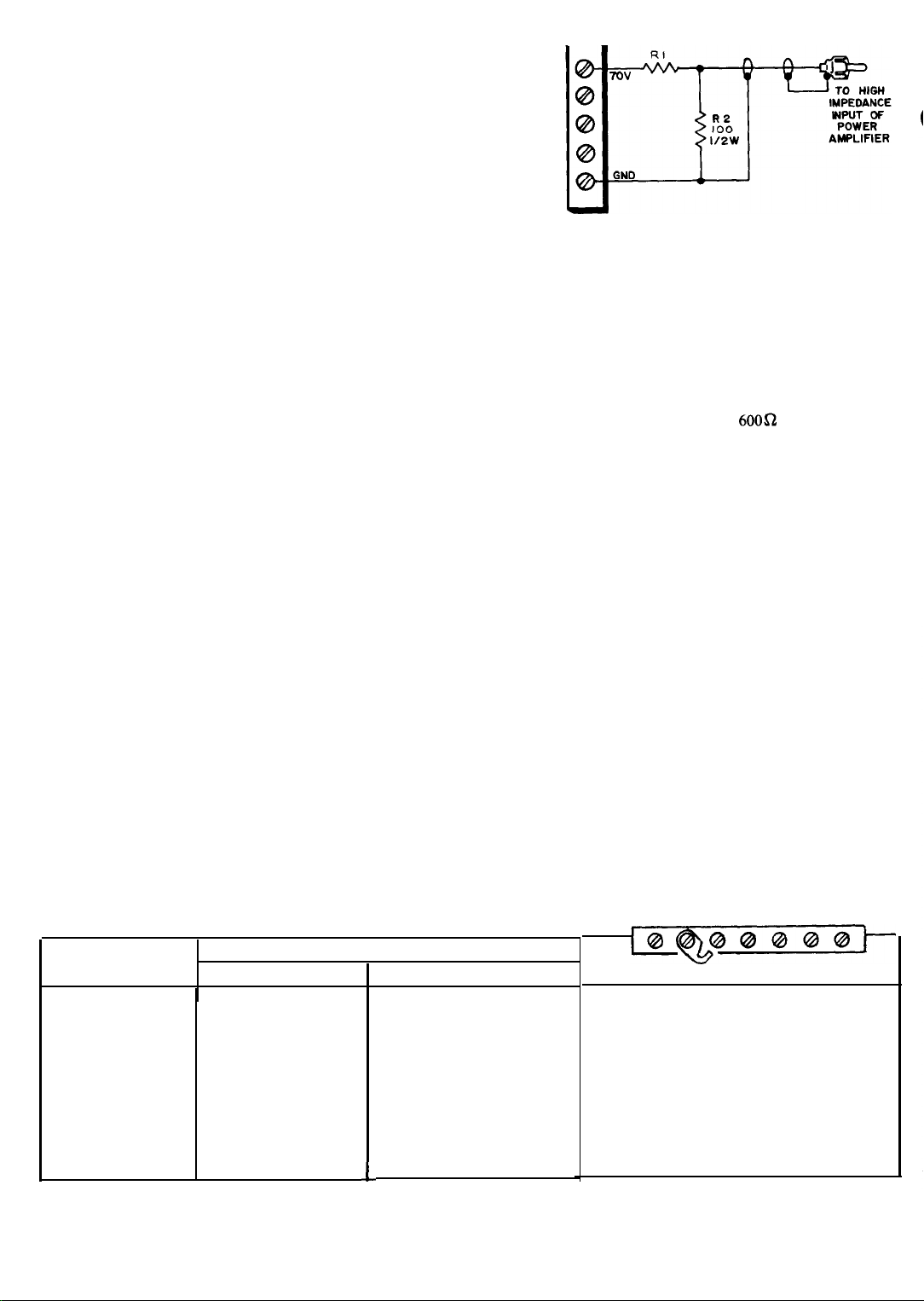
AT 70V RI
AT
25V
RI =
Figure 1
-
IOK,
3.3K,½W
½W
Input from another amplifier
-
74-0736-A
Balanced bridging input
The inputs for two or more amplifiers may be paralleled
without loss of gain. To do this, install a Bogen Model
transformer in socket Xl. Connect the 6OOa source to the BAL
LOW Z terminal strip on the rear of the unit. Use the two
outside terminals on the strip and connect the cable shields to
the GND terminal. If an unbalanced input is required, connect a
jumper from the GND terminal to an adjacent input terminal.
TLlOO
Input from another amplifier
The amplifier can be driven from a standard public address
amplifier that provides a 25-volt or 70-volt constant voltage
output. To do this, connect the output of the amplifier to one of
the Hi-Z INPUT jacks via a resistor network (see figure 1). The
resistors shown in figure 1 are in addition to the normal
loudspeaker load on the output of the public address amplifier.
OUTPUTCONNECTIONS
CA UTION
Be sure to
connecting amplifier output.
A variety of outputs is provided from the amplifier, either
balanced or unbalanced. Refer to Table
connections. Generally, the ground link does not need to be
connected unless an unbalanced output is especially desired.
foIlow 1ocaI
electrical codes when
1
for appropriate
OUTPUT
VOLTAGE
*110V
7ov
50V
MT 60A
260
83.3
42
45V
32.5V
31v
‘16
25v 8to 10.5
* 13v
12.5V
*Unbalanced output
**Disconnect link
only
between COM and
-
-
2.8
2.5
-
TABLE 1
Output Connections
IMPEDANCE (ohms)
MT 125B
125
40
20
16
8to 10
-
4 to 5
1.4
1.25
GND
2
1 2
3 4 5 6 7
**
JUMPER
OUTPUT3-7
"
"
"
"
"
"
"
1 to3OUTPUT
5-7
36
4-6
3-6
3-5
l-2
34
2-7
Page 3

Figure 2
External level control for
-
amplifiers
to a single speaker line. Typical output connections are shown in
Table 2. Note:
GND straps
on all except AMP I must be opened.
Input connections
If the amplifier Hi-Z inputs are being driven directly, simply
parallel the amplifier Hi-Z inputs with a phono patch cord, and
connect the input line to one amplifier. When a balanced input
transformer is being used, parallel the inputs at the screw
terminals.
70V constant-voltage output
For 70V constant voltage operation, connect the speaker
leads to the 70V and COM terminals on the rear of the unit. If
grounding is required, connect the link from COM to
25V
constant-voltage output
For
25V
constant-voltage unbalanced operation, connect the
speaker leads to 25V and COM, leaving the link connected
between COM and GND. For balanced operation, open the link
between COM 1 and GND. If the output transformer center tap
must be grounded, connect
a jumper
between 25VCT and GND.
GND.
CONNECTING AMPLIFIERS IN SERIES
CAUTION
Connect only amplifiers of the same model in
series; do not mix
MTl25B
Bogen
series to increase total power output where absolutely necessary
or MT60A amplifiers may be connected in
different
amplifier types.
TABLE 2- Amplifier Series Connection
Level control adjustment
It
is extremely important that the amplifiers have the same
gain and produce equal power output. This adjustment is most
easily accomplished by setting both amplifier level controls to
maximum and then providing an external gain control as shown
in figure 2. Make sure speech filter switches are in the same
position. If an external control cannot be provided, amplifier
gain must be set with the use of an external tone source,
adjusting the amplifiers to produce the same output with inputs
paralleled. Always keep level controls at approximately the
same position even when setting up the amplifiers.
CONNECTING AMPLIFIERS IN PARALLEL
It is not recommended that amplifiers be connected in
parallel. However, this is sometimes unavoidable. If it is
necessary to connect amplifiers in this configuration, consult
our Engineering Department for instructions.
POWER CONNECTIONS
The booster amplifier may be operated from
to 56VDC.
120VAC
or 48V
No.
of
Amplfs.
2
3
2
2
2
MT60A
MT60A
MT60A
MT125B
18OW,
375w,
120W,
250W,
120W,
25OW,
250W
12051
output
7ov
7ov
25v
120v
7ov
AMP
AMP
1
opoo
3 Z5V WINDINGS IN
AMP 1
00
000
AMP 1
AMP 1
3
Connections
1
AMP 2 AMP 3
AMP 2
AMP 2
AMP 2
AMP
000 0 0
SERIES
2
OUT
70V
. OUT
25V
OUT
120V
OUT
7ov
OUT
Page 4

Figure 3
DC
-
connections
Thermal breaker
If the thermal breaker opens, there will be no audio output
but the AC power lamp will remain on. Wait approximately five
minutes for the breaker to reset. If the breaker resets and then
opens again, investigate the cause of the high temperature
overload. This may be due to improper connections at the
output terminals or to excessive environmental heat with
inadequate ventilation. The thermal breaker will open when the
temperature at any one of the output transistors is excessive.
MAINTENANCE
120VAC source
Connect the AC power cord to a
wire receptacle with the center pin connected to earth ground.
12OVAC
source. Use a
48V-56VDC source
Connect the amplifier to a DC source capable of delivering
power indicated in the Technical Specifications table. A
polarized plug is supplied with the amplifier for making DC
connections. Connect DC cable to source, making certain to
observe proper polarity. An isolation diode should be used in
series with the DC supply as in figure 3.
OPERATION
VOLUME CONTROL
A volume control located on the rear of the unit is used
primarily to compensate for variations in preamplifier output
levels. The VOLUME control permits the gain of the amplifier
to be preset so that the preamplifier volume control may be
operated near the center of its range, rather than at an extreme
maximum or minimum. The VOLUME control is a screwdriver
adjustment which needs to be set only once for any given
preamplifier input.
DC POWER OPERATION
When the amplifier is operated from a DC power source, the
AC power switch and AC power indicator lamp will be
inoperative. Turn the amplifier on and off from the power
switch on the DC power supply or by inserting and removing the
DC power leads on the rear of the unit.
AC OPERATION
There are two overload protective devices used with AC
operation, the circuit breaker and the temperature overload
thermal breaker.
AC circuit breaker
If the circuit breaker opens, the AC power lamp will go out
and the amplifier will have no output. Set the AC power switch
to off and momentarily depress the red button on the circuit
breaker to reset it. Return the AC power switch to on. If the
breaker trips again, do not attempt to reset it but have the
trouble investigated by a qualified technician.
There are no user-replaceable parts within the
3-
unit. Have all internal servicing done by a
qualified technician.
CA UTION
BOGEN SERVICE
We are interested in your Bogen equipment for as long as you
have it. If trouble ever develops, do not hesitate to ask our
advice or assistance. Information can be obtained by writing to
Service Department, Bogen Division, P.O. Box 500, Paramus,
N.J. 07652.
When communicating with us, give the model and series
designation of your unit. Describe the difficulty and include
details on the electrical connections to and the types of
associated equipment, such as preamplifier, speakers, etc. We
will send you service information if the trouble appears simple.
If the trouble requires servicing, we will send you the name and
address of the nearest authorized Bogen service agency.
Before returning any equipment to Bogen, contact the Bogen
Service Department at the above address. If you do ship the
unit, pack it carefully to avoid damage in transit. Send the unit
fully insured and prepaid. It will be promptly repaired and
returned to you freight collect.
REPLACEMENT PARTS
Most components used in the amplifier are standard parts
available through reputable parts suppliers. The parts listed
here may be obtained from Bogen distributors, service agencies
or directly from the factory. When ordering a part, specify the
part number and the description of the part as listed. Specify the
model of the unit and give the series designation, which is a letter
followed by numbers, stamped on the chassis. For parts on
circuit boards, also give the component board assembly
number, which begins with
When replacing transistors, use those made by the manufacturers specified. Transistors from other suppliers may not be
satisfactory. Certain resistors must be Allen-Bradley. These are
designated by “AB” on the schematic diagram.
Replacing transistors
If a transistor must be unsoldered for testing or replacement,
be certain to remove all power from the unit to prevent possible
voltage transients in the circuit which might damage the
transistor. To prevent overheating the transistor when soldering
or unsoldering a lead, grip the lead between the point of heat
and the case with pliers or tweezers. These will act as a heat sink
to conduct heat away from the transistor. Do not bend a
transistor lead closer than 1 / 16” from the transistor case.
“45”.
4
Page 5

Power transistors must be properly mounted to insure good
heat dissipation. Make certain there is no foreign matter on the
contact surfaces between the transistor and the heat sink and
brush a thin coating of heat transfer compound (such as Dow
Corning No. 340 Compound silicon grease) on both surfaces.
Similarly coat any insulators used between the transistor and
the heat sink and secure the transistor firmly to the heat sink.
Schematic
Ref.
Cl01
Cl02
C201
C202
CB201
CB102
CR101
CR202,
203
CR102
LlOl
QIOI,
102
Q101-106
R204
Part No.
79-l 18-004
79-l
79-509-05s
79-
118-006
94-0017-09
94-0017-18
94-0014-07
96-52024 1
96-5241-01
96-5373-01
95-5173-01
96-5385-01
96-5385-01
76-114-101
Description
Chassis
Cap, elect, 8800
Cap, elect, 13,000
18-002
Capacitor, electrolytic, 6000
(MT-6OA)
Cap, elect, 5000
Circuit breaker, hold,
(MT-6OA)
Circuit breaker,
Thermal breaker, 105°C
Diode, HVR3
Diode, 300 piv @ 3A
Bridge rectifier, 35A (MT-125B)
Coil, .5
Transistor,
Transistor,
Resistor, .1 ohm, 5W (MT-60A)
µH
(MT-60A)
(MT-125B)
µF,
µF,
3.9A
2N3055H
or
2N3055H
75V (MT-125B)
µF, 4OV
(MT-125B)
µF,
50V (MT-60A)
1.65A
(MT-125B)
(MT-60A)
RCA
RCA
75V
R102, 103,
105, 106
R104,
107
SlOl
T201
TlOl
T202
T102
FlOl
FlOl
c2
C4
c9
Cl0
CR1-4
R3
R4
R8
Rll
R16, 17
R20
Sl
76-l 14-099
76-l 14-107
81-100-001
83-755-000
83-794-000
83-450-000
83-454-000
94-0005-
18
94-0005-20
45-7084-01
45-7048-01
79-5 12-040
79-008-065
79-008-062
79-l 12-001
96-5333-01
96-5321-01
96-5365-o 1
96-5316-01
96-5327-01
77-001-743
75-l 54-304
75-154-104
75-154-124
76-520-680
76-107-096
76-l 14-101
8 I-003-067
Resistor,
Resistor, 3.3 ohm, 5W (MT-125B)
Switch, power
Transformer, power
Transformer, power (MT-125B)
Transformer, output
Transformer, output (MT-125B)
Fuse, 3A slo-blo
Fuse,
P.C. board
Board assembly (MT-125B)
Board assembly
Capacitor, tantalum, 6.8 µF, 35V
Cap, electrolytic, 10
Cap, elect, 100
Cap, elect, 500
Diode, 400 piv @ 1A
Transistor, MPS-6767
Transistor, MPS-A56
Transistor,
Transistor,
Control, 200 kohm, screw-adjust
Resistor, 300 kohm,
Resistor, 100 kohm,
Resistor, 120 kohm,
Resistor, 68 ohm,
Resistor,
Resistor, .l ohm, 5W
Switch, slide DPDT
6¼A
retardant
.22
ohm, 5W (MT-125B)
(MT-6OA)
(MT-6OA)
(MT-60A)
slo-blo (MT-125B)
(MT-60A)
µF,
63V
µF,
50V
µF,
65V
(2N6107)
(2N6292)
1/4W,
1%
1/4W,
1%
1/4W,
1%
1/2W, 5%,
.82
ohm, 2W
(MT60A)
fire
Page 6

 Loading...