

Page 1
MODELS MT60
&
MT125A
Solid-State
PA Components
INSTALLATION
UNPACKING
The amplifier was thoroughly checked before leaving the
factory. Inspect the amplifier and shipping container
carefully for evidence of improper handling during shipment. In case of damage, make an immediate claim to the
dealer or distributor from whom the unit was purchased. If
the amplifier was shipped to you, notify the carrier without
delay and file a claim.
INPUT CONNECTIONS
Keep the input lead away from the output lead and ac
power cables. Unless the driving source provides a
low-impedance output, keep the input lead under ten feet
MT60
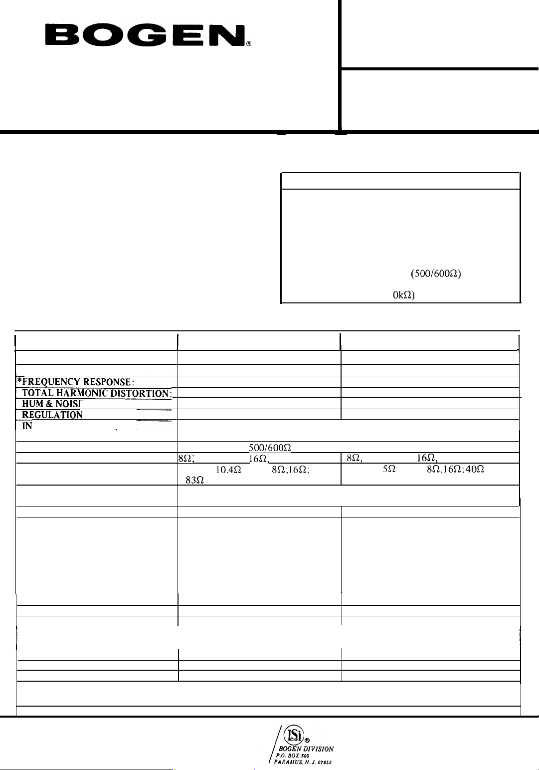
POWER OUTPUT:
PEAK OUTPUT:
E:
:
PUT SENSITIVITY (FOR
RATED OUTPUT):
INPUT IMPEDANCE:
OUTPUT CONNECTIONS:
OUTPUT IMPEDANCE
(BALANCED OR UNBALANCED):
CONTROLS AND INDICATORS:
SEMICONDUCTORS:
POWER CONSUMPTION:
AUXPOWERRECEPTACLE:
OVERLOAD PROTECTION:
DIMENSIONS:
WEIGHT:
60 watts
120 watts
±2 dB,
30 Hz to 20k Hz
Less than 2% at rated output
-80
dB
below rated output
Less than 2
Hi Z
Hi Z 50k; Lo Z
25VCT, 25V,
25VCT;
AC power switch, ac power indicator lamp, volume control, music-speech selector
switch.
6 silicon transistors; 7 diodes 8 silicon transistors; 7 diodes
120VAC 60HZ. 168 watts @Rated
output
120VAC
(No Output) (No Output)
48-56 VDC, 1 Amp
output
48-56 VDC, 15 mA
Output)
550
AC circuit breaker. 1
circuit breaker. I
breaker, 95°
approximately 2 minutes.
8” W. x
18½
Ibs.
dB
variation from no load to full load.
0.2V;
Lo Z balanced with TL600 xfmr,
16fi, 70V terminals
(25V);
(70V)
60HZ, 22
watts
C.
with recovery in
13”
D. x 6¼” H.
TABLE I. COMPANION UNITS AND ACCESSORIES
Model
CAM
CM
CHS-M
CTM
MX6A-5
RPK-I 8
TL600 Low-impedance
TL10K
with TL600 xfmr; Bridging
8R;
@
watts
.65A
Quiescent
@
30 watts
@
Quiescent (No
.65A
Hold: DC
Hold; Thermal
60-Watt
and
125-Watt
Booster Amplifiers
Description
Five input solid-state preamplifier mixer.
Five input solid-state preamplifier mixer.
Seven input solid-state preamplifier mixer.
Seven input solid-state preamplifier mixer.
Six input solid-state preamplifier mixer.
Rack mounting kit 19” x 7” (mounts 2
units).
plug-in
transformer.
Bridging (1
125 watts
250 watts
±2 dB,
40 Hz to 20k Hz
Less than 2% at rated output
-80 dB
below rated output
.045V;
25VCT, 25V,
25VCT;
(7OV)
120VAC
120VAC 60HZ, 30 watts
48-56 VDC,
48-56 VDC, 15
390 watts
AC circuit breaker.
8” W. x
25
60HZ, 300 watts @ Rated
output
Output)
circuit breaker,
breaker, 104” C. with recovery in
approximately 2 minutes.
13”
Ibs.
plug-in transformer.
MT125A
Hi Z with TL
lOk
(25V); 8R, 16R; 40R
2.25
Amps @ 62.5
mA @
D. x 6¼” H.
10k
with TL
70V terminals
@
Quiescent
Quiescent (No
2.5A
Hold; DC
2.5A
Hold; Thermal
xfmr,
10k
watts
0.lV.
xfmr.
*Variations in performance
PRINTED IN U.S.A.
3-75
PMP #1390
characteristics normally
LEAR SIEGLER, INC.
will not
exceed I
dB.
54-5521-01
Page 2
in length. Refer to Table I for
Bogen
preamplifiers suitable
for use with the amplifier.
HIGH IMPEDANCE INPUT: The amplifier can be driven to
mV
full output from any source developing 200
across one
of the Hi-Z inputs. Wire a single-conductor, low-capacity
shielded input cable to a standard phono plug (Cinch
18A,
or equivalent) and connect to one of the Hi-Z jacks on the
rear of the chassis.
LOW IMPEDANCE INPUT: The amplifier may be driven
Bogen
from a low-impedance
TL-600 transformer is installed in socket
chassis. Connect a twisted, shielded pair
X1
(Bogen
Model
on top of the
BB-8450,
or equiv.) input cable to the BAL. INPUT LOW Z terminal
strip on the rear of the unit. Use the two terminals on the
right of the strip and connect the cable shield to the GND
terminal on the left. If an unbalanced input is required,
connect a jumper from the GND terminal to the adjacent
input terminal.
CAUTION
Remove all power from unit before installing
transformers.
BRIDGING INPUT: The inputs for two or more amplifiers
may be paralleled without loss of gain. To do this, install a
Bogen
Model
TL-IOK
transformer in socket X1 on top of
the chassis. Connect the bridged inputs to BAL LOW Z
terminal strip on the rear of the unit. Use the two terminals
on the right of the strip and connect the cable shields to the
GND terminal on the left. If an unbalanced input is
required, connect a jumper from the GND terminal to the
adjacent input terminal.
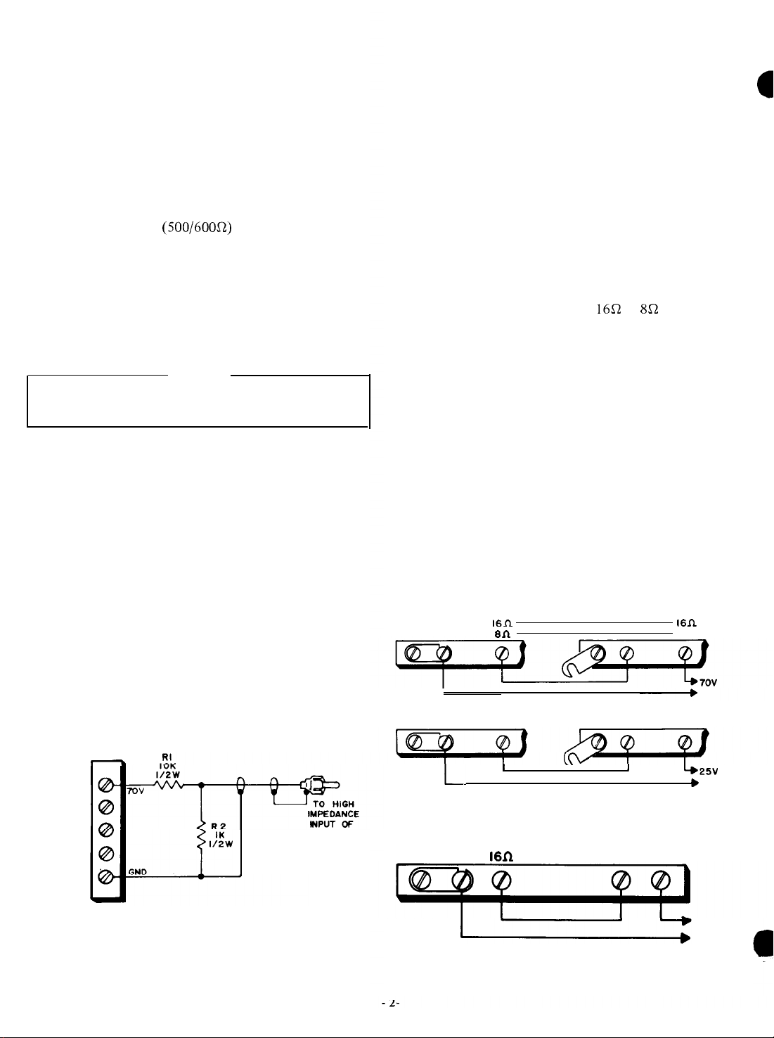
CONSTANT-VOLTAGE INPUT: The amplifier can be
driven from a standard public address amplifier that
provides a
25volt
or
70-volt
constant voltage output. To do
this, connect the output of the amplifier to one of the Hi-Z
INPUT
resistors shown in
jacks
via a resistor network (see figure 1). The
figure 1
are in addition to the normal
loudspeaker load on the output of the public address
amplifier.
OUTPUT CONNECTIONS
Speakers may be connected with standard flexible line
cord (zip-cord) and up to 100 feet of cable may be used
without appreciable loss. Class II wiring is acceptable unless
prohibited by local codes.
70V
CONSTANT-VOLTAGE
OUTPUT. For 70V constant-
voltage operation, connect the speaker leads to the 70V
and COM 2 terminals on the rear of unit. If ground-
ing is required, connect a jumper from the COM 2 to GND.
25V
CONSTANT-VOLTAGE OUTPUT. For
25V
constantvoltage unbalanced operation, connect the speaker leads to
25V
and COM 1, leaving the link connected between
COM
1
and GND. For balanced operation, open the link
COM 1
between
and GND. If the output transformer center
tap must be grounded, connect a jumper between 25VCT
and GND.
16 OHM
&
8 OHM OUTPUT.
For 16fi or 8R operation,
connect the speaker leads between the desired output
1.
terminal and COM
If ungrounded operation is desired,
open the link between COM 1 and GND.
CONNECTING AMPLIFIERS IN SERIES
Pairs of
Bogen MT1 25A
amplifiers or MT60 amplifiers
can be connected in series to effectively double the power
output into the same loadline. See Figure 2 for connection
diagrams. Be certain to remove the link between COM 1 and
GND of amplifier No. 2.
Depending on the impedance of the signal source, apply
the input signal to the HI Z or LO Z input of amplifier No.
1. Use jumpers to connect the appropriate input of
amplifier No. 2 in parallel with that of amplifier No. 1.
It is necessary that both amplifier volume controls be at
the same setting to assure that each amplifier will share the
load equally.
AMPLIFIER I
COM1
GND
AMPLIFIER I
GND
COM1
25VCT
AMPLIFIER 2
COM1
GND
AMPLIFIER 2
GND
COM1
FOR MT60
8R FOR MT125
874-1017-01
25VCT
_
a
OUTPUT
TERMINAL
STRIP OF
DRIVER
AMPLIFIER
AT 70V RI . 10K,
AT
25V
RI -
3.3K, ½W
Figure 1 - Connection to Constant -
P.A. Amplifier Driver.
½W
74-0730-A
POWER
AMPLIFIER
Voltage
Figure 2 - Connecting Amplifiers in Series
GND COM I
A74-2018-01
Figure 3 - MT1
MT60 AND
25A
Connections for
MT125A
COM2 7ov
120-Volt
Operation
120V
125W
Page 3

CONNECTIONS FOR
(MT125A
Figure 3 shows connections for
selected frequencies for laboratory or industrial
applications.
POWER CONNECTIONS.
The booster amplifier may be operated from 120 vac or
48V
to
120 VAC SOURCE. Connect the ac power cord to a 120
vac. source. Use a 3-wire receptacle with the center pin
connected to earth ground.
If desired, auxiliary equipment may be connected to the
AUX POWER receptacle on top of the unit. Do not exceed
power ratings on the schematic diagram.
48V
source capable of delivering power indicated in the Technical Specifications table. A two-prong polarized plug
Part No.
supplied with the amplifier for making dc connections.
Connect dc cable to source making certain to observe
proper polarity.
VOLUME CONTROL
A volume control located on the rear of the unit is used
primarily to compensate for variations in preamplifier
output levels. The VOLUME control permits the gain of the
amplifier to be preset so that the preamplifier volume
control may be operated near the center of its range, rather
than at an extreme maximum or minimum. The VOLUME
control is a screwdriver adjustment which needs to be set
only once for any given preamplifier input.
DC POWER OPERATION
When the amplifier is operated from a dc power source,
the ac power switch and ac power indicator lamp will be
inoperative and there will be no power at the AUX POWER
receptacle on top of the chassis. Turn the amplifier on and
off from the power switch on the dc power supply or by
inserting and removing the dc power leads on the rear of
the unit.
ONLY)
56V
dc.
-
56V DC SOURCE. Connect the amplifier to a dc
85-0109-01;
120-VOLT
Cinch Jones No. P-302-CCT) is
OUTPUT
120-volt
output at
(Bogen
MAINTENANCE
AC OPERATION
There are two overload protective devices used with ac
operation, the circuit breaker and the temperature overload
thermal breaker.
AC CIRCUIT BREAKER. If the circuit breaker opens, the
ac power lamp will go out and the amplifier will have no
output, but there will be power at the AUX POWER
receptacle on top of the unit. Set the ac power switch to
off and momentarily depress the red button on the circuit
breaker to reset it. Return the ac power switch to on. If the
breaker trips again, do not attempt to reset it but have the
trouble investigated by a qualified technician.
THERMAL BREAKER. If the temperature thermal breaker
opens,
power lamp will remain on. Wait approximately two
minutes for the breaker to reset. If the breaker resets and
then opens again, investigate the cause of the temperature
overload. This may be due to improper connections at the
output terminals or to excessive environmental heat with
inadequate ventillation. The thermal breaker will open
when the temperature at any one of the output transistors
is excessive.
DC OPERATION
operation, the circuit breaker and the temperature overload
thermal breaker. If either device opens, there will be no
audio output. The ac power lamp does not light during dc
operation.
THERMAL BREAKER, See the applicable paragraph under
“AC OPERATION”.
REPLACING TRANSISTORS
are considerably more reliable than the best vacuum tubes.
This is why some transistors are soldered into equipment
like resistors or capacitors. If the unit is inoperative, it
generally is safe to assume that the transistors have not
failed and that the trouble is elsewhere in the equipment.
replacement, be certain to remove all power from the unit
to prevent possible voltage transients in the circuit which
might damage the transistor. To prevent overheating the
transistor when soldering or unsoldering a lead, grip the
lead between the point of heat and the case with pliers or
tweezers. These will act as a heat sink to conduct heat away
from the transistor. Do not bend a transistor lead closer
than
good heat dissipation. Make certain there is no foreign
matter on the contact surfaces between the transistor and
the heat sink and brush a thin coating of heat transfer
compound (such as Dow Corning No. 340 Compound
silicon grease or equivalent) on both surfaces. Similarly coat
any insulators used between the transistor and the heat sink
and secure the transistor firmly to the heat sink.
BOGEN SERVICE
you have it. If trouble ever develops, do not hesitate to ask
our advice or assistance. Information can be obtained by
writing to Service Department,
500, Paramus, N.J. 07652.
designation of your unit. Describe the difficulty and
include details on the electrical connections to and the
types of associated equipment, such as preamplifier,
speakers, etc. We will send you service information if the
trouble appears simple. If the trouble requires servicing, we
-3-
there will be no audio output but the ac
There are two overload protective devices used with dc
Transistors show little, if any, deterioration with age and
If a transistor must be unsoldered for testing or
1/
16” from the transistor case.
Power transistors must be properly mounted to insure
We are interested in your
When communicating with us, give the model and series
Bogen
equipment for as long as
Bogen
Division, P.O. BOX
Page 4

will send you the name and address of the nearest
authorized
Do not return the unit to
Bogen
service agency.
Bogen
without prior clearance
from our Service Department. If you do ship the unit, pack
it carefully to avoid damage in transit. Send the unit, fully
insured and prepaid, via United Parcel or Railway Express.
Do not ship via parcel post unless so instructed.
service agencies or directly from the factory. When ordering
a part, specify a part number and description of the part as
listed. Specify the model of the unit and give the series
designation,
which is a letter followed by numbers,
screened on the chassis. For parts on circuit boards, also
give the component board assembly number, which begins
with “45”.
REPLACEMENT PARTS
Most components used in the amplifier are standard
parts available through reputable parts jobbers. The parts
listed here may be obtained from
Ref. No.
Al
Part No.
45-9933-01
45-9938-01
94-5067-01
Printed Circuit Board
c2
C5
C9,ll
Cl0
CR1,3,4,5
CR2
Ql
79-008-063
79-008-062
79-112-002
79-l 12-007 (MT60)
96-5333-01
96-5202-01
96-5321-01
MPS-6767 (Motorola)
Q2
96-5342-01
MJE 172 (Motorola)
45-9866-01
45-9865-01
R17,19
R18,20
76-107-105
76-l 16-003
Bogen
distributors,
(MT60)
(MT1 25A)
(MT1
25A)
When replacing transistors, use those made by the
specified manufacturers. Transistors from other suppliers
may not be satisfactory. Certain resistors must be
AllenBradley. These are designated by “AB” on the schematic
diagram.
Ref. No.
CHASSIS ELECTRICAL PARTS
Cl04
Part No.
79-509-054
(MT60)
79-509-075 (MT1 25A)
Cl05
CBlOl, 102
CB103 94-00
79-009-07 1
94-0017-15 (MT125A)
14-03
CR 101,102,
103
96-5241-01 (MT60)
96-5355-01 (MT125A)
1101 94-0302-04
QlOl,
103
96-5351-01
2N6254
(RCA) (MT60)
(MT60)
QlOl-104
RlOl
SW1
SW102
TlOl
96-5315-01 (MT125A)
77-001-372
81-003-059
8 l-002-098
83-776-000 (MT60)
83-766-000 (MT1 25A)
T102
83-427-O 10 (MT60)
83-425-000 (MT1 25A)
OWNER’S WARRANTY
Bogen solid
workmanship for one year from the date of sale to the original purchaser, provided that the
equipment has not been subjected to abuse or accident or altered in any way. Any part of the
equipment covered by this warranty which, with normal installation and use, becomes defective
will be
insured to our authorized service station or to the
Forest Avenue,
or will be returned to you freight prepaid.
Models containing vacuum tubes carry the same warranty as above, except that
apply to the vacuum tubes, which are guaranteed for 90 days.
The registration card enclosed with the equipment must be completed and mailed within five
days of purchase
state sound and intercom equipment is guaranteed against defects in material and
repaired
or replaced by
Paramus,
to place
Bogen,
provided the equipment IS delivered or
New Jersey 07652. The equipment may be picked up by you personally
the warranty in effect.
-4-
Bogen
Factory
Service
shipped
Department, Route 4 and
prepaid and
it
does not
Page 5

 Loading...