

Page 1
© 2010 Bogen Communications, Inc.
All rights reserved.
Specifications subject to change without notice.
54-2194-01C 1307
MPS1, MPS2
Mini Pendant Speakers
Models MPS1B /MPS2B (Black),
MPS1W/MPS2W
(White)
Installation and Use Manual
Page 2
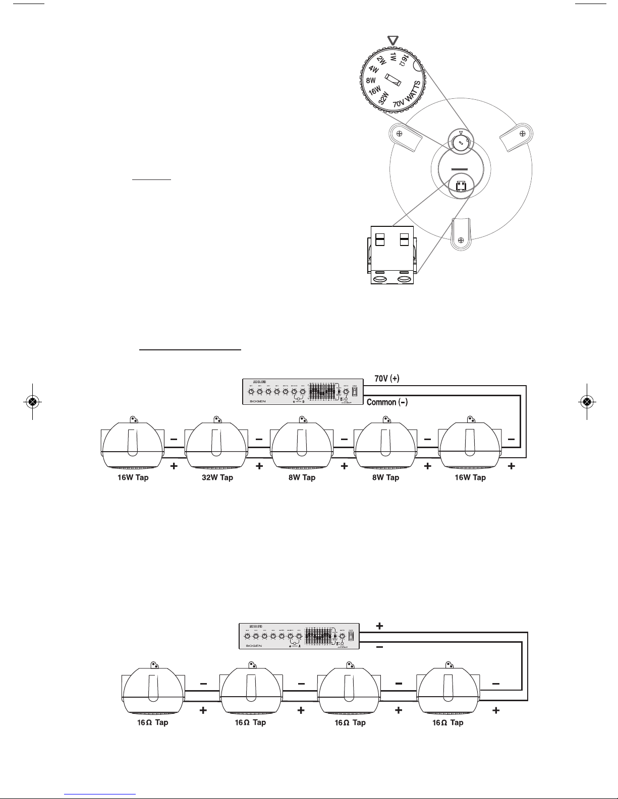
Power Tap Selection
16-ohm or 70V
The Power Tap selector switch is used to set the
appropriate power level or impedance for your
system. Rotate the switch until the power level
you require lines up with arrow.
IMPORTANT: When connecting to a 70V amplifier,
make sure that the Tap Selector switch on the
speaker IS NOT
set in the “16Ω” position.
Speaker Connection and Polarity
Speaker wiring is terminated at a snap-lock input
connector, with a positive and negative terminal.
All wiring should be done prior to installation and
then plugged into the rear of the speaker. Wire all
speaker polarities the same way.
70V System Configurations
When designing a 70V system, the total of all power tap settings of all the connected
speakers CANNOT EXCEED
the output power of the 70V amplifier (amplifier power
can exceed the sum of the speaker loads).
Low-Impedance System Configurations
When wiring together multiple MPS1/2 speakers that are set to 16 ohms, it is important to
calculate (using Ohmʼs Law) the total load that these speakers present to the amplifier.
The total load impedance of the interconnected speakers cannot be lower than the
minimum load impedance rating of the low-impedance amplifier. Also, care must be
taken to ensure the amplifier cannot overdrive the speakerʼs maximum power rating.
POWER TAP
SELECTOR SWITCH
SNAP-LOCK
WIRING TERMINAL
MPS1/2
(Top View)
100W Amplifier
with 70V Output
200W Max. Low-Impedance
Amplifier
4-ohm direct
GND
EXAMPLE: 16 + 32 + 8 + 8 + 16 = 80 Watts minimum amplifier output rating.
EXAMPLE: Four 16 -ohm speakers in parallel = 4 ohms. Also in this example,
the amplifier output power rating capability should not exceed 200W (4 X 50W,
the MPS1/2).
_
+
Page 3

IMPORTANT: The MPS1/2 Mini Pendant is not an outdoor speaker. DO NOT expose the
speaker to rain or moisture. The MPS1/2 should be installed by qualified personnel.
NOTE: ALONG WITH THE MAIN DROP CABLE, YOU MUST ALSO
USE A
SAFETY CABLE WHEN SUSPENDING AN MPS1/2 PENDANT
SPEAKER. BE SURE TO SECURE
ALL RIGGING POINTS AND
FOLLOW ALL THE CABLE MANUFACTURERʼS
MATERIAL
RECOMMENDATIONS & INSTALLATION INSTRUCTIONS. FAILURE
TO DO SO MAY RESULT IN PROPERTY DAMAGE, INJURY
OR
DEATH, AND LEGAL LIABILITY FOR YOU AND/OR YOUR COM
PANY.
Attach the main drop cable to the MPS1/2 Main Drop Cable hole in the Suspension
Attachment located on the top of the speaker. This Main Drop Cable will be the primary
connection that will hold all the suspended speakerʼs weight to the anchor point.
Likewise, attach the Safety Cable to the Safety Cable hole in the Suspension Attachment.
This Safety Cable is meant to be a safeguard only, so when attaching to an anchor point
allow for a small amount of slack in the wire, as the Safety Cable should not bear any of
the speakerʼs direct supension weight to keep the speaker hanging level.
MPS1/2 Speaker Cable Connections
and Suspension Instructions
In addition to the Main suspension Drop Cable,
a backup Safety Cable is required for proper
installation. Use wire rope or other drop line rated
for at least 100 lbs. to ensure a proper safety
margin.
The attachment point on the structure from which
the speaker is to be anchored also must be able to
handle 100 lbs.
NOTE:
If using suspension cables with a cladding,
be sure to strip away any coating so that clamping
device being used will be pressed in direct contact
with the bare wire cores.
MAIN DROP
CABLE HOLE
MINI PENDANT
SPEAKER
MPS1/2 SUSPENSION
ATTACHMENT
SAFETY
CABLE HOLE
MAIN
DROP
CABLE
SAFETY
CABLE
TO SPEAKER
ANCHOR
POINT
Page 4

50 Spring Street, Ramsey, NJ 07446 USA
Tel. 201-934-8500 • Fax: 201-934-9832
www.bogen.com
The Bogen MPS1 & MPS2 Mini Pendant Speakers are warranted to be free from defects in material or workmanship for two (2) years
from the date of sale to the original purchaser. Any part of the product covered by this warranty that, with normal installation and use,
becomes defective will be repaired or replaced by Bogen, at our option, provided the product is shipped insured and prepaid to: Bogen
Factory Service Department, 50 Spring Street, Ramsey, NJ 07446, USA. The product will be returned to you freight prepaid. This warranty does not extend to any of our products that have been subjected to abuse, misuse, improper storage, neglect, accident, improper
installation or have been modified or repaired or altered in any manner whatsoever, or where the serial number or date code has been
removed or defaced.
THE FOREGOING LIMITED WARRANTY IS BOGEN'S SOLE AND EXCLUSIVE WARRANTY AND THE PURCHASER'S SOLE AND
EXCLUSIVE REMEDY. BOGEN MAKES NO OTHER WARRANTIES OF ANY KIND, EITHER EXPRESS OR IMPLIED, AND ALL
IMPLIED WARRANTIES OF MERCHANTABILITY OR FITNESS FOR A PARTICULAR PURPOSE ARE HEREBY
DISCLAIMED AND EXCLUDED TO THE MAXIMUM EXTENT ALLOWABLE BY LAW. Bogen's liability arising out of the manufacture,
sale or supplying of products or their use or disposition, whether based upon warranty, contract, tort or otherwise, shall be
limited to the price of the product. IN NO EVENT SHALL BOGEN BE LIABLE FOR SPECIAL, INCIDENTAL OR CONSEQUENTIAL
DAMAGES (INCLUDING, BUT NOT LIMITED TO, LOSS OF PROFITS, LOSS OF DATA OR LOSS OF USE DAMAGES) ARISING OUT
OF THE MANUFACTURE, SALE OR SUPPLYING OF PRODUCTS, EVEN IF BOGEN HAS BEEN ADVISED OF THE POSSIBILITY
OF SUCH DAMAGES OR LOSSES. Some States do not allow the exclusion or limitation of incidental or consequential
damages, so the above limitation or exclusion may not apply to you. This warranty gives you specific legal rights, and you may also have
other rights which vary from State to State.
Products that are out of warranty will also be repaired by the Bogen Factory Service Department — same address as above or call
201-934-8500. The parts and labor involved in these repairs are warranted for 90 days when repaired by the Bogen Factory Service
Department. All shipping charges in addition to parts and labor charges will be at the owner's expense. All returns require a Return
Authorization number.
7/22/2008
Limited Warranty; Exclusion of Certain Damages
Technical Specifications
Frequency Response (-10dB)* MPS1: 50Hz to 14kHz; MPS2: 50Hz to 22kHz
Driver Complement MPS1: 4-1/2” Dual-Cone Wide-Range; MPS2: 4-1/2” Woofer, 3/4" Coaxial Tweeter
Sensitivity (1W/1m) MPS1: 86dB (Average 100Hz to 10kHz); MPS2: 87dB (Average 100Hz to 15kHz)
Dispersion 140 degrees
Impedance Range Low (16 Ohms) / High (70V)
Power Input (Maximum) 50W @ 16 Ohms; 32W @ 70V
Power Settings (in watts)** 70V; 32, 16, 8, 4, 2, 1
Enclosure Material ABS Plastic Injection-Molded
Grille Material Powder-Coated Perforated Steel
Terminations Snap-Lock Input Plug Screw Terminals
Product Weight MPS1: 4 lb, 8 oz.; MPS2: 5 lb.
Speaker Dimensions 12” Dia.. x 7-7/8” High
Included Accessory (1) Snap-Lock Input Plug
Optional Accessories Hanging Cable Kit (CK10, white or black)
Enclosure Finish & Color Textured White or Black
* Free-Space Response, 16-ohm input
** Rear Panel switch selected
 Loading...