

Page 1

LMM1S
LMM1S
MIC/L INE
IN
LMM1S
Mic/Line Input Module
Features
• Line mode for high impedance input
• MIC Mode for low impedance input
• Electronically balanced input
• Gain/Trim control with Gain range switch
• Bass and treble
• 24V Phantom power
• Audio Gating
• Gating with threshold and duration adjustments
• Fade back from mute
• 4 levels of available priority
• Can be muted from higher priority modules
• Can mute lower priority modules
• Removeable screw terminal input
© 2007 Bogen Communications, Inc.
54-2156-01A 0706
Specifications subject to change without notice.
MIC/LINE
IN
Page 2
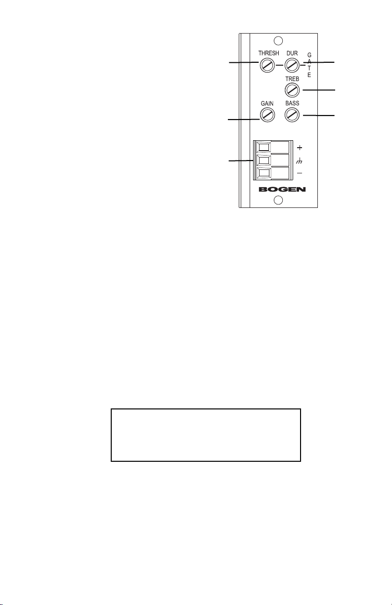
5. Gain
Provides control over the level of input signal that can be applied to the internal signal buses
of the main unit. Balances the input levels of various devices so that the main unit controls can
be set to relatively uniform or optimum levels. 18-60 dB Gain range in MIC position, -2 to 40
dB in Line position.
1. Gate - Threshold (Thresh)
Controls the amount of input signal level necessary to turn the module’s signal output on and
mute lower priority modules. Clockwise rotation
increases the necessary input signal level required
to produce audio output and mute lower priority modules.
6. MIC/Line In
MIC/Line level input on removeable screw terminal strip. Electronically balanced input.
3. Treble (Treb)
The Treble control provides +/- 10 dB at 10 kHz.
Clockwise rotation provides boost; counterclockwise rotation provides cut. Center position
provides no effect.
2. Gate - Duration (Dur)
Controls the amount of time the signal output
and priority muting of the module remains
applied to the main unit’s buses after the input
signal falls below the required minimum signal
level (set by the threshold control).
4. Bass
The Bass control provides +/- 10 dB at 100 Hz. Clockwise rotation provides boost; counterclockwise rotation provides cut. Center position provides no effect.
LMM1S
MIC/L INE
IN
1
5
6
2
3
4
WARNING:
Turn off power to unit and make all jumper
selections before installing module in unit.
LMM1S
MIC/LINE
IN
Page 3

Module Installation
1. Turn off all power to the unit.
2. Make all necessary jumper selections.
3. Position module in front of any desired module bay opening, making sure that the module
is right-side up.
4. Slide module onto card guide rails. Make sure that both the top and bottom guides are
engaged.
5. Push the module in to the bay until the faceplate contacts the unit’s chassis.
6. Use the two screws included to secure the module to the unit.
Gating
Gating (turning off) of the module’s output when insufficient audio is present at the input can
be disabled. Detection of audio for the purpose of muting lower priority modules is always
active regardless of this jumper setting.
Phantom Power
24V Phantom power can be supplied to condensor microphones when jumper is set to ON
position. Leave OFF for dynamic mics.
Bus Assignment
This module can be set to operate so that the mono signal can be sent to the main unit’s
A bus, B bus, or both buses.
MIC/LINE Switch
Sets input gain range for the intended input device. MIC gain range 18 – 60 dB, LINE gain
range -2 – 40 dB.
Jumper Selections
Priority Level
*
This module can respond to 4
different levels of priority.
Priority 1 is the highest priority.
It mutes modules with lower priorities and is never muted.
Priority 2 can be muted by
Priority 1 modules and can mute
modules set for Priority Level 3
or 4. Priority 3 can be muted by
either Priority 1 or 2 modules
and can mute Priority 4 modules. Priority 4 modules are
muted by all higher priority
modules. Remove all jumpers for
“no mute” setting.
*The number of priority levels avail-
able is determined by the equipment the modules are used in.
G ATING
ENABLED
DISABLED
PRIORITY LEVELS
HIGHEST
1234
LOWEST
GATING
ENABLE
PRIORITIES
J11
J10
ASSIGNMENT
BUS
J13
J12
J4
BUS ASSIGNMENT
B
BOTH
A
LINE MIC
PHANTOM
PWR
J2
MIC/LINE
SWITCH
LINE LEVEL INPUT
MIC LEVEL INPUT
PHANTOM
POWER
ON
OFF
Page 4

LMM1S
MIC/L INE
IN
50 Spring Street, Ramsey, NJ 07446, U.S.A.
201-934-8500; Fax: 201-934-9832
www.bogen.com
Block Diagram
Input Wiring
Balanced Connection
Use this wiring when the source equipment
supplies a balanced, 3-wire output signal.
Connect the shield wire of the source signal
to the "G" terminal of the input. If the "+"
signal lead of the source can be identified,
connect it to the plus "+" terminal of the input. If the source lead polarity cannot be identified,
connect either of the hot leads to the plus "+" terminal. Connect the remaining lead to the minus
"-" terminal of the input.
Note: If polarity of the output signal versus the input signal is important, it may be necessary to
reverse input lead connections.
Unbalanced Connection
When the source device provides only an
unbalanced output (signal and ground),
the input module should be wired with
the "-" input shorted to ground (G). The
unbalanced signal's shield wire is connected to the input module’s ground and
the signal hot wire is connected to the
"+" terminal. Since unbalanced connections do not provide the same amount of noise immunity
that a balanced connection does, the connection distances should be made as short as possible.
MIC/LI NE
IN
MIC/LI NE
IN
SOURCE
EQUIPMENT
MIC/LINE
IN
SOURCE
EQUIPMENT
MIC/LINE
IN
JUMPER WIRE
MIC/LINE
INPUT
+
GND
_
INPUT
ATTEN.
MIC/LINE
 Loading...