

Page 1
Iw
BOGEN
COIVIMUNICATIOfSia, INC.
AUTO-REVERSE CASSETTE
TAPE PLAYER
AND FM-STEREO/FM/AM TUNER
OPERATING INS I KUCTIUNS
CPT-1A
DESCRIPTION
The Bogen Model CPT-lA is a compact, integrated
unit consisting of a stereo/mono cassette tape player
and an FM-stereo/FM/AM tuner. It provides a reliable,
economical source of background music for a sound
system. Program continuity is assured by the auto •
matic tape reverse feature, which changes the direction
when the tape reaches the limit of its travel.
The CPT-IA operates on 120 volts AC. It incorpo -
rates a low-level, low impedance output, which will
drive the auxiliary input of a P.A. amplifier. The unit
can also drive 8-ohm loudspeakers directly with its
irncmal stereo amplifier (five watts per channel).
If desired, the CPT-IA may be mounted in a standard
19" equipment rack by means of the optional RPK-55
Rack Panel Kit,
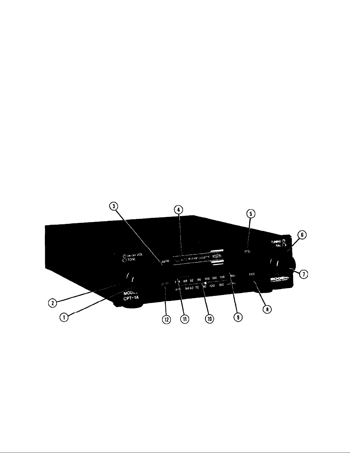
CONTROLS AND FtlNCnONS
1. ON/OFFf/OLUME 7.
2. TONE - clockwise rotation increases TREBLE;
counterclockwise rotation increases BASS. ' 8.
3. AM/FM SELECTOR - OUT for FM-stereo/FM; IN
for AM, 9.
4. AUTO REVERSE CASSETTE - insert cassette until 10.
it engages; unit automatically goes from radio to
tape playing mode, 11.
5. FAST forward (& REWIND)/EJECT CASSETTE-
For rapid advance of tape, press slowly to Position 12.
1. For rewind, press PROG, then FF/EJ slowly to
Position 1. For removal of cassette, press in fully
to Position 2. For normal operation, FF/EJ must
be in released position
6. balance - clockwise rotation increases sound to
the right channel; counterclockwise rotation
increases sound to the left channel.
TUNING- rotate control in either direction to select
desired radio frequency.
. TAPE PROGRAM - press to reverse the direction
and play the opposite side of the cassette tape.
TAPE DIRECTION INDICATORS
FREQUENCY SCALE - illuminated scale indicates
radio frequency being received.
FM-STEREO SIGNAL INDICATOR illuminates
when FM-stereo radio signal is being received.
MO/ST SWITCH - for normal FM-stereo reception
set this switch to the OUT position, fnss the
switch IN for monaural operation, when receiving
weak signals that cause the FM-STEREO indicator
to come on and off, or to eliminate the aimoying
background noise from weak FM-stereo stations
while tuning.
Page 2

TO PLAY A CASSETTE TAPE
The door of ihe CPT lA is hinged and will open and
close with the insertion and removal of the cassette.
1. Rotate the power ON/OFF/VOLUME switch
clockwise and increase volume slightly.
2. Check cassette to be certain that the tape is
tightly wound on the reels.
3. Insert the narrow end of the cassette into
receptacle, with exposed tape toward the right.
When the cassette is fully inserted it will
automatically begin to play (the unit will switch
from radio to the tape player mode).
4. When the tape reaches Uie limit of Its travel, the
CPT^IA will automatically reverse direction and
play the opposite side of the cassette. You may
manually reverse direction of play at any time by
pressing the PROG button.
5. a. To advance tape rapidly, press FF/EJ, a two
position switch, slowly until it locks into the
first position.
b. To rewind tape rapidly, press PROG, then
FF/EJ slowly until it locks into the first posi ■
tion.
c. To discontinue either of the above and
return to normal operation, press and release
FF/EJ.
6. To remove the cassette, firmly press FF/EJ-to the
second (EJECT) position.
IMPORTANT NOre
Always remove the cassette from the CPT-IA
after use to prevent damage to the cassette
and tape drive mechanism.
FM/AM OPERATION
1. Rotate the power ON/OFF/VOLUME switch clock ■
wise and increase volume slightly.
2. Select either FM or AM radio band by pressing
AM/FM button.
3. Select desired position of the MO/ST mode switch.
4. Rotate tuning Imob to locate the desired radio frequency as indicated on frequency scale.
ROirriNE MAINTENANCE
Periodic cleaning of the tape head, capstans, and pinch
rollers will ensure high quality reproduction of
program material and tioublc-free operation. The unit
should be clean«l every 20 to 30 hours of operation.
Use of a good quality cassette cleaning cartridge is
recommended; if one is not readily available, proceed
as follows:
1. Saturate a cotton swab with isopropyl (rubbing)
alcohol.
2. While holding the cassette door open, locate the
tape head (to the right of the opening and toward
the center of the unit).
3. Clean the tape head, capstans, and pinch rollers
with the cotton swab.
4. Allow parts to dry before operating the unit.
OVERLOAD PROTECTION
The CPT-IA is protected by an internal 100mA, slow
blow fuse. If this fuse opens, the unit will shut down
completely: have the trouble investigated by a
qualified technician.
CAtrnON
There are no user-serviceable parts within the
unit. To avoid an electric shock hazard, have
all internal servicing performed by qualified
service personnel only. The warranty will
become void if repairs are made by other than
the Bogen Service Department or authorized
service agency.
Page 3

COMMUNICATIONS, INC.
IM
AUTO-REVERSE
CASSETTE
TAPE PLAYER
AND FM-STEREO/FM/AM
IMPORTANT ANTENNA INFORMATION
Articles 810 and 820 of the National Electric Code,
ANSI/NFPA No. 70-1978 provides information regarding
antenna grounding. The CPT-IA is designed for connection
to various antenna systems as illustrated in Figures 1 through
3.
CAUnON
Use No. 8 AWG aluminum wire, or larger, as
ground wires for both mast and lead-in and
secure to building structure with insulators
spaced from 4 to 6 feet (1.22m. to 1.83m.)
apart. Mount antenna discharge unit as closely
as possible to where the lead-in enters the
building structure.
'— FM LINE ANTENNA. The CPT-1A line cord may be used as an
internal FM Line Anterma for receiving FM broadcasts (see
Figure 1). For improved reception, particularly in weak
signal areas or for tuners mounted in consoles or racks,
installation of an outdoor FM or 'T" anterma is necessary.
TUNER
CPT-1A
Figure 2 - Connecting Indoor FM Antenna, 300 Ohm System
HI-2 AM ANTENNA WIRE
t
INSULATOR I
ANTENNA
DISCHARGE'
UNIT
y'
GROUNDING ELECTRODE
DRIVEN e‘ (2.44M)
INTO THE EARTH
INSULATED
lead-in
GROUND
CLAMP
Figure 1 - Connecting Outdoor AM Antenna and FM Line
Antenna
EXTERNAL FM ANTENNA. If you are installing a standard
300-ohm antenna system, connect the twin-lead transmission
line as shown in Figure 2. If conditions require use of a
coaxial transmission line, such as RG-H or RG-59, coimect
the cable as shown in Figure 3. Always disconnect the FM
line anterma when using an external FM antenna.
BOGEIM
so SPRING STREET, P.O. Bo* 57S
RAMSEY. NJ 07446 »34-SSOO
-75n FM
ANTENNA
GROUND
CLAMP
MAST
GNO-
WlflE
ANTENNA
discharge
UNIT
GROUNDING ELECTRODE
DRIVEN 8' (2.44M)
INTO THE EARTH.
DOWNLEAD OR
^lead-in wire
RG ll/
OR RGSS
'X GROUND
CLAMPS
SHIELD
DISCONNECT
line antenna
Figure 3 - Connnecting Outdoor FM Antenna, 75 Ohm
System
COMMUNieATiaNBitNC.
«
Drlnia^H in l/n,nn 0700 c*.cnco_rM
a7*-«jr-oi
 Loading...