

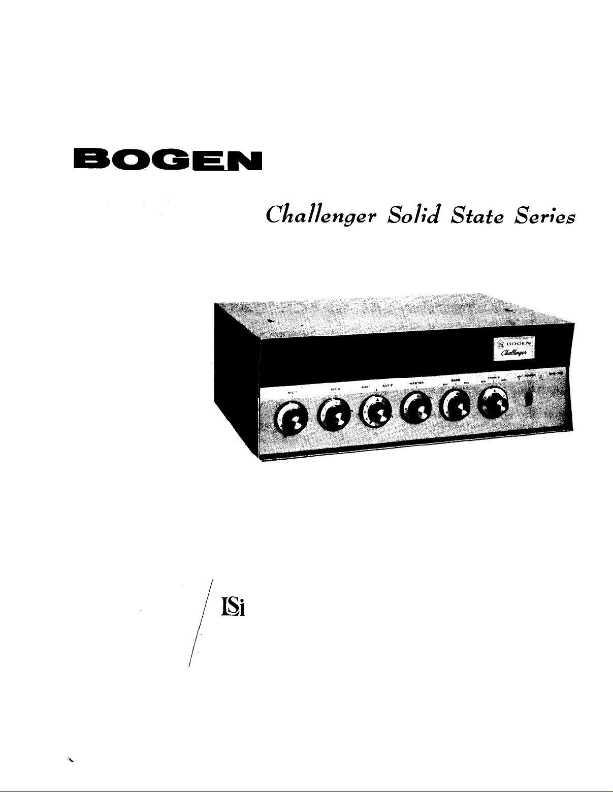
Page 1
LEAR
SIEGLER,
MODEL
100 WATT TRANSISTOR
PUBLIC
ADDRESS AMPLIFER
CHS100
.
IS1
INC.
INSTALLATION AND OPERATING MANUAL
READ THOROUGHLY BEFORE OPERATING EQUIPMENT
0
BOGEN
P.O.
PARAMUS, N. J. 07652
COMMUNICATIONS
BOX 500
DlVlSlON
Page 2

DESCRIPTION
The Bogen Model CHSlOO is a fully transistorized
public address amplifier rated at 100 watts. The unit
will accommodate two microphone inputs and two
auxiliary inputs for a tuner, tape recorder, or phono-
graph with a ceramic cartridge. The amplifier will
accommodate either high or low impedance microphones, and no transformer is required to change from
one microphone impedance to the other.
An optional accessory designed to mount on the
front panel of the CHSlOO provides two additional
high or low impedance microphone inputs. A BRIDGING
receptacle on the rear panel accepts additional
level, ‘high-impedance signals from a unit having its
own volume control. such as a
corder or tuner. The BRIDGING receptacle can also
be used as a high-impedance output to feed a tape
recorder or auxiliary amplifier. The master volume
control will not affect the bridging output level.
preamplifier, tape
high-
re-
TECHNICAL SPECIFICATIONS
1
POWER OUTPUT: 100 watts at less than 5%
distortion.
PEAK POWER: 200 watts.
FREQUENCY RESPONSE: 40 to 20,000 Hz
SENSITIVITY: Hi Z MIC, 4 mv; Lo Z MIC, 0.3 mv;
AUX, 0.3 volt; Bridging, 1 volt.
HUM AND NOISE
65 db; AUX input, 70 db.
INPUTS: 2 MIC, high (100 K ohms) or low (200
ohms) impedance; 2 AUX (300
ing (high impedance).
OUTPUTS: 2, 8, 16 ohm speakers; 25 volt CT
balanced
or BOOSTER,
pedance at 0.5V.
(below rated output): MIC input,
(m);
70 volt balanced
10K
at 5V; Bridging, high im-
Kfi);
(4%);
±2
db.
Bridg-
TAPE
Individual volume controls are provided for each
microphone input. A fader volume controls selects and
adjusts the level of the desired auxiliary input and
permits fading between the two inputs. A master volume control regulates the mixed output level.
arate
bass and treble controls permit adjustments for
tonal balance.
Outputs are provided for 2, 8 and
and for 25-volt and
systems. Two quick-disconnect plugs provide rapid
and convenient connections to speakers. The output
of the CHSlOO amplifier can also be fed to a tape re-
corder or booster amplifier.
The CHSlOO amplifier operates from a 105-125
volt AC source, and has a total power consumption
of 150 watts. A 1.75-ampere circuit breaker protects
the amplifier against overloads.
CONTROLS: 2 MIC volume; 1 AUX volume (fader
for two inputs);
TREBLE tone; POWER switch and indicator.
TONE CONTROL ACTION: Treble (at 10 K Hz),
t 11 db to -12 db, Bass(at 50 Hz), +10 db to
-10 db.
POWER REQUIREMENTS: 105 to 125 volts, 50 or
60 cycles AC, 150 watts.
SEMI-CONDUCTORS: 10 silicon transistors, 2
diodes.
DIMENSIONS:
SHIPPING WEIGHT: 24 pounds.
15¼”
70-volt
balanced speaker line
MASTER volume; BASS,
wide x
lO½”
16-ohm
deep x
5½”
Sep-
speakers
high.
ACCESSORIES
PMA-2 ADD-ON PREAMPLIFIER
The Bogen Model PMA-2 Preamplifier is designed
to provide two additional microphone channels for the
CHSlOO amplifier. Each preamp channel has its own
volume control and will accommodate either high-impedance or low impedance microphones. The unit is
connected to the Preamp Accessory socket on the top
chassis of the CHSlOO amplifier. When installed, the
PMA-2 control knobs protrude through the front panel
of the CHSlOO amplifier.
WMT-I LINE MATCHING TRANSFORMER
The Bogen WMT-1 line input/line output matching
transformer is an accessory which has been designed
-2-
especially for matching
500/600
to a
former it may be used
distributing background music which has been transmitted over leased telephone lines. The, accessory
also functions as an output matching transformer in
feeding special program material over a 500/600 ohm
telephone line for transmission to a local broadcast
studio.
LVP-I ACCESSORY
The Bogen Model LVP-1 is a plug-in accessory
which permits the user to provide microphone precedence when used with a customer supplied switch
ohm line.
either inputs from or outputs
As an input matching
with the Bogen amplifier for
trans-
Page 3
and the Bogen amplifier. The LVP-1 may also be used
as
a remote volume control in conjunction with the
Model RVC-1 remote volume control.
RVC-I REMOTE VOLUME CONTROL
The Bogen Model RVC-1 accessory permits the
amplifier to provide remote volume control when used
in conjunction with LVP-1 accessory.
MODEL LPC-4 PHONO PLAYER TOP
Model LPC-4 is a complete four-speed phono-
player designed to be mounted directly on top of the
amplifier. The unit comes complete with all necessary
hardware, and can be easily installed and connected
to amplifier with only a screwdriver. A tone arm
hous-
ing a dual-stylus turnover cartridge is included with
record player.
LK-IO CONTROL GUARD LOCKING PLATE
The Bogen Model LK-10 control guard locking
plate is designed to prevent unauthorized tampering
with the controls of amplifier. It comes complete with
two sets of keys. The key cannot be removed when
the lock is in open position.
RPK-27 RACK PANEL
The Bogen Model RPK-27 rack panel kit is designed to mount the
out the PMA-2 preamplifier) in a standard 19”
rack. The rack panel is finished in gray enamel.
INSTALLATION
UNPACKING power cables.
Inspect the shipping container and amplifier for
indications of improper handling. The amplifier was
carefully checked before leaving factory. If the unit
has been damaged, make an immediate claim to the
dealer
or distributor from whom it was purchased. If
the amplifier was shipped to you, notify the trans-
portation company without delay and place your claim.
CONNECTIONS BETWEEN COMPONENTS
For high-impedance inputs, use single-conductor,
low-capacity shielded wire for connecting the record
player, tape recorder, and other components to the
amplifier. Keep leads under ten feet in length.
For low-impedance microphone inputs, use
singleconductor shielded wire, in lengths from 50 to 500
feet depending on the characteristics of the microphone.
Speakers may be connected with standard flexible line cord (zip-cord), and up to 100 feet of cable
may be used without appreciable loss.
Make certain that all input cables are kept away
from speakers cables, power cables, and power trans-
formers, and that speaker cables are kept away from
POWER AND
The amplifier is furnished with an AC line cord
terminated in a three-prong plug. Plug the line cord
into a three-wire grounded outlet providing a nominal
120-volt, 50-60 cycle power source. This
the amplifier as well as supply power to it.
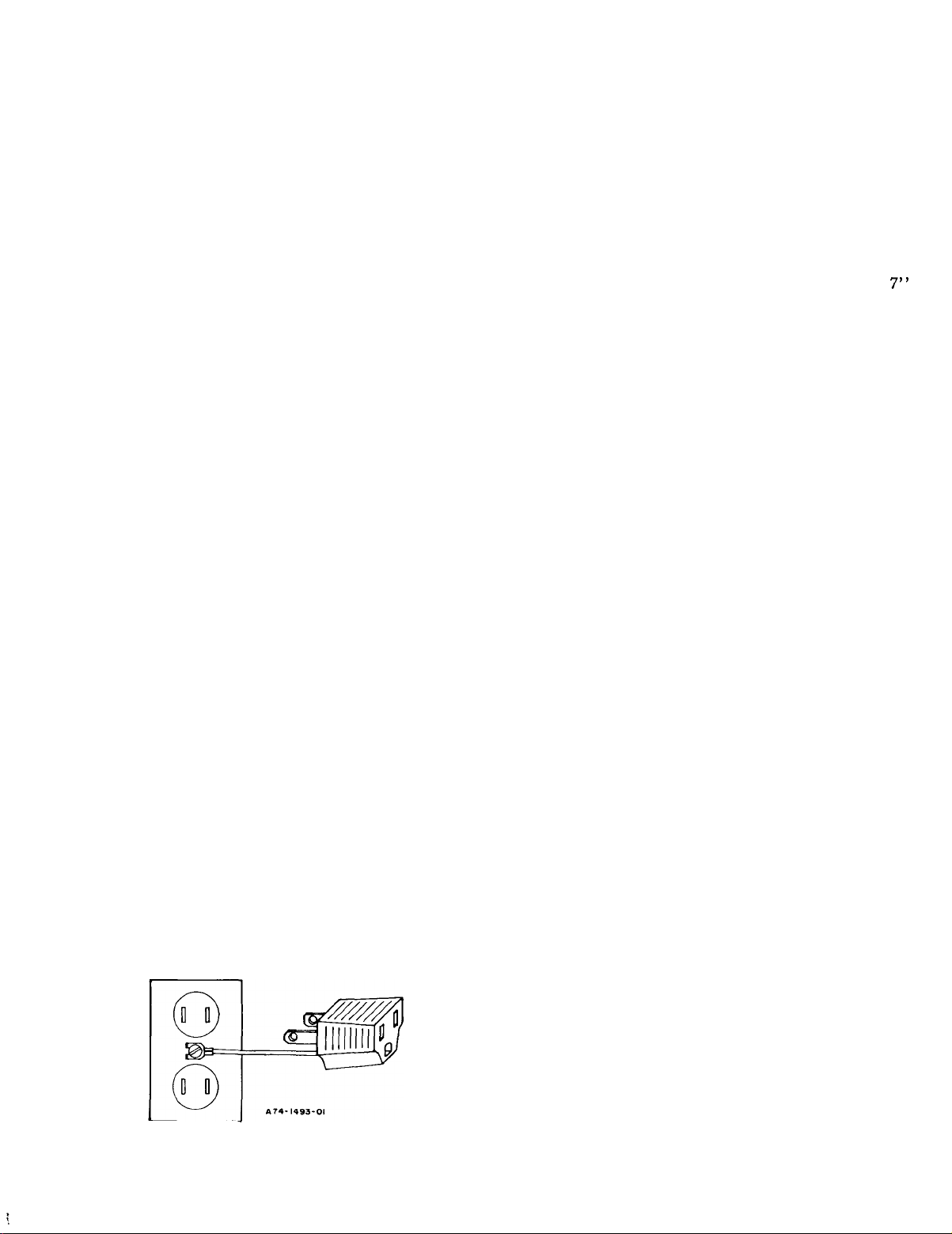
It is advisable to ground the amplifier. Therefore,
if a three-wire outlet is not available, an adapter such
Leviton
as
ard two-wire outlet for use with three-wire plugs. The
adapter is provided with a grounding pigtail which
should be connected to the screw holding the wall plate
to the receptacle, as shown in figure 1.
In some areas, the
grounded. In this case it will be necessary to
connect a grounding wire between the GND ter
minal
water or steam pipe.
No. 5017 should be used to convert a stand-
on the rear chassis of the amplifier and a
CHSlOO
GROUNDlNG
NOTE
amplifier (with or with-
will
ground
wall plate
screw is not
x
7”
INPUT CONNECTIONS
MICROPHONES
Two microphones may be connected to the amplifier, and either or both may be used simultaneously.
Either high or low-impedance microphones may be
used. The amplifier is shipped with an adaptor in the
microphone receptacles, which permits high-impedance
microphone inputseither from a phone plug or from
a standard
MClF
Figure 1
microphone connector.
-
Grounding Line Cord Adapter
Z:
Connect a high-impedance microphone (10,000
HI
ohms or more) to the MIC 1 HI
Z
receptacle on the
rear panel of the amplifiet (see figure 2). Connect a
second high-impedance microphone to the receptacle
marked MIC 2 HI
Z.
Use a single-conductor shielded
cable, terminating either in a phone plug or a standard
microphone connector (Amphenol 75-MClF or equiv-
alent). Remove the adaptor from the microphone receptacle when the phone plug is used. The cable
length from the microphone to the amplifier should be
kept under 10 feet.
LO Z: Connect low-impedance microphones (600 ohms
or less) to the LO Z terminal strip on the rear panel
(see figure 2). Use a single-conductor shielded cable.
The conductor is connected to the MIC 1 terminal and
the shield to GND. Connect a second low-impedance
microphone to the terminal strip in the same manner,
with the high side of the cable to the MIC 2 terminal
-3-
Page 4

and the shield to GND. Low-impedance microphones
may be used with cable lengths from 50 to 500 feet,
depending on the characteristics of the microphone.
Remove the adapter plug from the microphone
receptacle when thelow-impedance input is used.
CAUTION
Figure 2
Rear View CHS100 Amplifier
-
PHONOGRAPH
Phonographs employing a ceramic or crystal type
cartridge may be connected to either the AUX 1 or
AUX 2 receptacle. Use single-conductor shielded
cable terminated in a standard single-prong phono
plug. It is recommended that a separate ground wire
be connected between the phono player base and the
GND terminal on the Output Terminal Strip on the rear
panel of the amplifier (see figure 2). This is not re-
quired when using the Bogen Model LPC-4 phono
player accessories.
AUXILIARY
A radio tuner, tape recorder or any other high-
level, high-impedance signal source may also be connected to the AUX inputs. An input level of at least
0.3 volts is required to obtain full output from the
amplifier.
The input from a 500/600-ohm line is also connected to the AUX receptacle through a WMT-1 line
matching transformer. For detailed connections, see
the instruction sheet furnished with the Bogen Model
WMT-1 accessory.
REMOTE VOLUMECONTROL
Each of the three input channels may have its
volume controlled remotely by utilizing Bogen LVP-1
and RVC-1 accessories. Remote control permits ad-
justment of volume from distances up to 2,000 feet.
The LVP-1 unit is plugged into the appropriate
REMOTE ACCESSORY SOCKET, located on the top
chassis (see figure 3). It is necessary to remove the
top section of the amplifier
cage to reach the accessory
sockets. This is done by loosening the two sheet
metal screws at the rear of the amplifier and lifting
the top section off.
The leads from the RVC-1 accessory are con-
nected to the MIC 1, MIC 2 or AUX terminal and
GND
on the REMOTE CONTROL PRECEDANCE strip on
the rear panel (see figure 2). Complete installation
information is contained in the instruction sheet furnished with the LVP-1 and RVP-1 accessories.
MIC
2
(LVP-I)
MIC I
(LVP-I)
Figure 3 - Location of Accessory Sockets
-4-
Page 5

MICROPHONE PRECEDENCE
Each of the microphone channels can be connected to provide precedence over the AUX channel
by means of the
ordinary single-pole, single-throw switch. The LVP-1
accessory
CESSORY socket on the top of the chassis (see figure
3). Connect the switch to the MIC 1 or MIC 2 terminal
on the REMOTE CONTROL PRECEDENCE strip on
the rear panel (see figure 2). For complete installation
information, see the instruction sheet furnished with
the LVP-1 and RVP-1 accessories.
Bogen
LVP-1 accessory unit and an
is plugged into the AUX REMOTE AC-
WMT-I ACCESSORY INPUT
To connect the input from a 500/600-ohm line,
mount the WMT-1 transformer on the WMT-1 mounting
holes on the rear chassis (see figure 2). Connect the
500/600-ohm
on the accessory. Connect the phono plug on the
1 to the AUX 1 or AUX 2 input of the amplifier.
input to the three-screw terminal board
WMT-
OUTPUT CONNECTIONS
NOTE
If
another sound source has been plugged into
the AUX input, the
the
MIC
input of the amplifier. However, the
WMT-1 wiring must first be modified, as described in the instruction sheet furnished with
the accessory.
WMT-1
may be connected to
AUXILIARY POWER
The auxiliary power receptacle is a three-wire
grounded outlet. Hence, any associated equipment connected to it with a three-prong line cord will be grounded, providing the amplifier line cord has been properly
grounded. Both the amplifier power switch and the
phono on-off switch must be used in turning off a
cordplayer connected to the auxiliary receptacle. Flats
may develop on the idler wheel of the phonograph if
only the amplifier power switch is used to stop the
record player.
re-
SPEAKERS
The amplifier may be used with speaker systems
rated at 2, 8 and 16 ohms and with
constant-voltage speaker systems. For detailed information on the installation of multiple speaker systems, refer to the Speaker Installation Instructions
(No. 54-5001-02) included with this unit.
In installations where speakers will remain connected to the amplifier permanently, connect the speaker directly to the output terminals on the rear panel
(see figure 2). Connect one lead to the terminal cor-
responding to the speaker system’s impedance and
the other lead to COM 1.
For 25-volt operation, connect leads between 25
V (6-8
operation, remove the shorting link between COM 1
and GND. Connect the high sides of the balanced
line between the 25 V (6-8
The balanced line ground is connected to the 25 VCT
(1.5-2
leads to the 70 V (4912) and COM 2 terminals. Connect a jumper between the COM 2 and GND terminals,
if grounding is desired. For balanced line operation,
disconnect the jumper between COM 2 and GND.
Q) terminal and COM 1. For balanced 25-volt
Q) and the COM terminals.
a)
terminals.
For
70-volt
operation,
connect the speaker line
25-volt
and
70-volt
For standard impedance loudspeakers and 25-volt
systems, connect the speaker line leads to pins 1 and
2 of the plug. Connect the wired plug to either speak-
er socket, then attach the impedance selector to the
appropriate output terminal which corresponds to the
impedance of the loudspeaker. For 25-volt systems,
the impedance selector is attached to the 25 V (6-812)
terminal.
For 70-volt operation,
are connected to pins 2 and 3 of the speaker plug.
Connect the impedance selector to the COM 2 terminal.
the speaker line leads
BRIDGING OUTPUT
The BRIDGING receptacle on the rear panel pro-
vides a high-impedance output to feed a tape recorder
or auxiliary amplifier. The MASTER Volume Control
will not affect the bridging output level.
WMT-I ACCESSORY OUTPUT
By utilizing a
a zero-level output at
for feeding a telephone line. The WMT-1 accessory is
connected to the WMT-1 HI
panel. See the instruction sheet furnished with the
WMT-1 transformer for complete installation directions.
Bogen
WMT-1 bridging transformer,
500/600
ohms may be obtained
Z
output jack on the rear
For installations that are moved constantly, connect the speaker to the speaker socket on the rear
panel. Two speaker plugs
are furnished with the amplifier for use in
connections to the speaker sockets.
(Bogen
Part No. 85-0147-01)
making
TAPE OR BOOSTER AMPLIFIER
To drive a booster amplifier or tape recorder, connect a patch cord (with a standard phono plug) from
the TAPE/BOOSTER output jack to the input of the
booster amplifier or tape recorder.
-5-
Page 6

CONTROL FUNCTIONS
POWER SWITCH
The POWER switch on the front panel turns the
amplifier ON and OFF.
MICROPHONE I
The MIC 1 control on the front panel is used to
adjust the volume of the Microphone 1 input. It is
turned clockwise (to the higher numbers) to increase
the volume and counterclockwise to reduce it. Set the
control to the zero position (indicated by a triangle)
when the Microphone 1 input is not used.
MICROPHONE 2
The MIC 2 control on the front panel is used to
adjust the volume of the Microphone 2 input. It is
turned clockwise (to the higher numbers) to increase
the volume and counterclockwise to reduce it. Set the
control to the zero position (indicated by a triangle)
when the Microphone 2 input is not used.
AUXILIARY
The AUX
pose. It selects either of the two auxiliary inputs and
it controls the volume of the selected auxiliary input. To select the AUX 1 input, rotate the control
counterclockwise past the center position (indicated
by a triangle between the two l’s). Turning this control more counterclockwise increases the AUX 1
volume.
To select the AUX 2 input, rotate the control
clockwise past the center position. Turn the control
more clockwise to increase the AUX 2 volume. If the
auxiliary input is not to be used, set the control to
the center position.
The control can be
trol when both auxiliary inputs are connected. This
makes it possible to gradually and smoothly reduce
the level of one input and then increase the other
when changing inputs. The effect is one of fading from
one auxiliary input to the other.
l/AUX
2 control serves a two-fold pur-
also
used as a “fader” con-
RESET MARKER
Each volume control has a red reset marker on the
skirt of the knob. This marker is used to log a par
ticular setting. This is done as follows. Adjust the
volume controls to the desired levels. Slide the reset
markers to coincide with the midpoint mark on the
front panel. The individual knob can now be returned
to zero or any other point, allowing instant resetting
to the predetermined level.
MASTER
Rotate MASTER control to maximum clockwise.
Set the MIC and AUX input volume controls to the
highest level likely to be used, and then mix inputs
as desired. Use the MASTER control to regulate the
overall volume of the output signal.
BASS
The BASS control is used to adjust the tonal
balance of the amplifier output. The center position of
the control (indicated by a triangle between the two
l’s) provides flat frequency response. Rotation of
this control in the counterclockwise direction reduces
(cuts) bass response of the amplifier. Clockwise rotation of the control increases bass response.
The BASS control may also be used to remove
low-frequency noise such as phono rumble or hum. In
situations where acoustic feedback (howling) is likely,
rotate this control counterclockwise. This reduces the
feedback effect and permits higher volume levels than
would other wise be possible.
TREBLE
The TREBLE control adjusts the tonal balance of
the amplifier output. The center position (indicated
by a triangle between the two l’s) provides flat fre-
quency response and is generally used when program
sources and speaker systems are of the highest qual-
ity. Rotation of the control in a counterclockwise
direction reduces the high frequency response of the
amplifier; clockwise rotation increases it. This con-
trol can also be used to remove high-frequency noise,
such as record scratch.
INSTALLATION AND
FEEDBACK
If speakers are located too close to the micro-
phone, acoustic feedback (squealing or howling) may
result. In this case, adjust the volume, and the BASS
and TREBLE controls if necessary, to the point
where feedback is eliminated. In addition, move the
speakers to increase the distance between the speakers and microphone.
HUM
A low-frequency hum may be heard if the con-
nections between the signal sources and the ampli-
fier are incorrect or defective. Recheck all connections for continuity if hum occurs. Try reversing the
amplifier power plug and the plugs of other units such
as the phono player connected in the system. Check
OPERATING
for broken wires, shields and poor connector contacts.
Keep input cables away from the speaker cables. Keep
speaker cables away from transformers and AC power
lines. In the case of a phono player, it may be
cessary to connect a separate ground wire from the
chassis of the phono player to the GND on the rear
of the amplifier.
HINTS
MICROPHONE TECHNIQUE
Speak directly into the microphone in a normal
voice, at a distance of approximately 6 inches to one
foot from the microphone.
Speak deliberately with even speed and loudness.
Don’t shout. Pause frequently between words-and pro-
nounce each word carefully. Sound final consonants.
Do not sing-song or drop words here and there.
-6-
ne-
Page 7

BOGEN
long as you have it. If trouble ever develops with
your unit, please do not hesitate to ask our advice or
assistance. Information can be obtained by writing to
Service Department, Bogen Communications, P.O.
Box 500, Paramus, New Jersey 07652.
ber and serial number of your unit. Completely des-
cribe the difficulty encountered and the effects each
operating control has upon the symptoms of trouble.
Include details on electrical connections to associated
equipment, and list such equipment. When we receive
this information, we will send you service information
if the trouble appears to be simple. If the trouble requires servicing, we shall send you the name and address of the nearest Bogen authorized service agency
to which you can send your unit for repairs.
using the original shipping carton, or a similar container and filler material, to prevent damage in tran-
CIRCUIT BREAKER
ectrical overload by a
reset the breaker, press the red reset button, located
on the top chassis left side, as shown in figure 2.
SERVICE
We are interested in your Bogen amplifier for as
When communicating with us, give the model num-
When shipping your unit, pack the amplifier well,
sit. Send the unit, fully insured and prepaid, via railway express. Do not ship via parcel post unless so
instructed. The unit will be promptly repaired and returned to you via express collect.
The amplifier circuitry is protected against el-
1¾
ampere circuit breaker. To
If the circuit breaker trips again, do not attempt
REPLACEMENT PARTS
The components used in Bogen equipment, with
exception of items listed below, are standard parts
through all reputable parts jobbers. However, several
parts are custom-made to strict Bogen specifications
and should be replaced only with genuine Bogen
parts. These custom-made parts are listed here and
available through Bogen distributors, service
are
agencies or direct from the factory.
Ref. No.
c2, c3
Cl2
Cl8
Cl9
Cl04
106
C105,
CBlOl
CRl,
CR2
Q3, Q4
Q7
QlOl,
Q102, Q103
Part No.
79-008-034
79-008-048
79-005-039
79-008-036
79-009-065
79-009-053
94-0008-02
96-5184-01
96-5213-01
96-5228-01
96-5
187-01
96-5213-01
96-5131-01
96-5162-04
Description
Capacitor, Electrolytic,
25 mfd,
Capacitor, Electrolytic,
50 mfd, 25V
Capacitor, Electrolytic,
1000 mfd,
Capacitor, Electrolytic,
50 mf d,
Capacitor, Electrolytic,
4000 mfd,
Capacitor, Electrolytic,
2000 mfd; 40V
Circuit Breaker, 2 Amp
Diode, 200 PIV, 3 Amp
Transistor
Transistor BC239C
Transistor S2285
Transistor
Transistor 40234
Transistor
15V
15V
15V
5OV
2N5089
2N5089
2N3055
(95V)
to operate the unit. Check the amplifier to determine
the cause of the overload, or consult a Bogen representative or competent serviceman.
TRANSISTOR REPLACEMENT
Transistors and semiconductor diodes do not ordinarily require routine testing.
does not perform properly and it is suspected that a
transistor or diode is at
nician should test them.
However,
dicate that a transistor might be faulty, it must be
removed from the circuit for checking. The plug-in
transistors, of course, can easily be replaced. When
replacing plug-in transistors, use Dow Corning N
340 Compound Silicon Grease (or equivalent). Brush
compound on heat sink, insulator, and transistor. Be
certain that no foreign matter is on heat sink, insulator, or transistor. To insure proper thermal contact, screw down plug-in transistors securely.
PRINTED CIRCUIT REPAIR
When testing or replacing components on the
printed circuit, take care not to damage the board by
application of excessive heat or pressure. A 40-watt
pencil iron normally is sufficient to unsolder com-
ponent parts. If component leads are cut, always pull
them through from the top of the board
from the printed side. Do not insert the leads of re-
placement components into the board without first
clearing the holes. This may be done by heating the
solder and inserting a pick from the underside of the
board.
When ordering a part, specify part number and
description of the part as listed below. Specify the
model and give the series designation, which is a run
letter followed by numbers, stamped or screened on the
rear of the chassis. Also, give the component board
assembly number
boards.
Ref. No.
R5
R17
R18
R28
R34
R35
R43
R44
R45
R46, R47
R48, R49
SW101
TlOl
T102
T103
7
if previous tests by a technician in-
(45-)
Part No. Description
77-00 l-646
77-001-649
77-00 l-649
77-00 l-647
77-001-648
77-00 l-648
76-
113-098
75-412-56 1
75-842-221
75-743-511
75-742-100
81-003-025
83-726-000
83-396-000
83-
397-000
94-0197-O 1
85-0147-O 1
03-0594-01
03-0595-01
02-9029-01
fault, only
for all parts mounted on PC
Control, AUX Volume (CT fader)
Control, MIC 1 Volume
Control, MIC 2 Volume
Control, Bass (BD taper)
Control, Treble (Audio taper)
Control, Master Volume
(Audio taper)
Resistor,
Resistor,
Resistor,
Resistor,
Resistor,
Switch, Power
Transformer,
Transformer, Driver
Transformer, Output
Bulb, No. 19
Plug, Speaker,
Knob & Skirt (O-10)
Knob
Reset Marker
When
the receiver
a qualified tech-
-
0.2m,
5 watt
56Oa,
2 watt
220Q,
3 watt
51012,
7 watt
l(M1,
7 watt
Power
3-pin
&
Skirt (5-O-5)
never pull
O.
Page 8

 Loading...