

Page 1
C O M M UIM1C A T10 N S, 1N C.
MIXER-PREAMPLIFIER
Model CAM is a fully transistorized mixer-preamplifier
providing four microphone inputs and one auxiliary input, and
supplying both microphone and high level outputs. While it
fulfilLs a wide variety of applications, the CAM is particularly
well suited for expanding the number of inputs of Bogen public
addre.ss amplifiers.
The CAM accommodates both high and low impedance
microphones, and has an input for crystal or ceramic cartridges,
tuners or other high level sources. Outputs are provided for high
impedance unbalanced or low impedance balanced or un
balanced microphone inputs and high level, high impedance
inputs to a public address amplifier, tape deck or similar
equipment. Units may be paralleled to provide a greater
number of inputs.
The CAM operates from either 120VAC, 60Hz or 25-28VDC
source. It may be mounted in a standard 19" equipment rack using
Bogen RPK35B Rack Mounting Kit or in a wall with Model
WMK-l In-^II Mounting Kit.
INSTALLATION
UNPACKING
Your unit was carefully checked before leaving the factory.
Inspect the shipping container and the unit carefully for
indications of improper handling. If the unit has been damaged,
make an immediate claim to the distributor from whom it was
purchased. If it was shipped to you, notify the transportation
company and place a claim.
POWER and GROUNDING
The AC line cord has a three-prong plug which should be
plugged into a three-wire, grounded 120V. 60 Hz outlet. If a
three-wire outlet is not available, use an adapter and secure the
pigtail lead to the grounded wall plate mounting screw. Ii is
important to ground the unit. If the wall plate screw is not
grounded, connect a wire from the GND terminal of the
mixer/preamplifier to a suitable earth ground.
Auxiliary power
A 24 to 28V external DC supply may be used to power the
unit and may remain connected when the unit is being powered
by the primary AC source. The power switch, when set to off,
disconnects both AC and DC supplies, turning the unit off.
Model CAM
INPUT CONNECTIONS
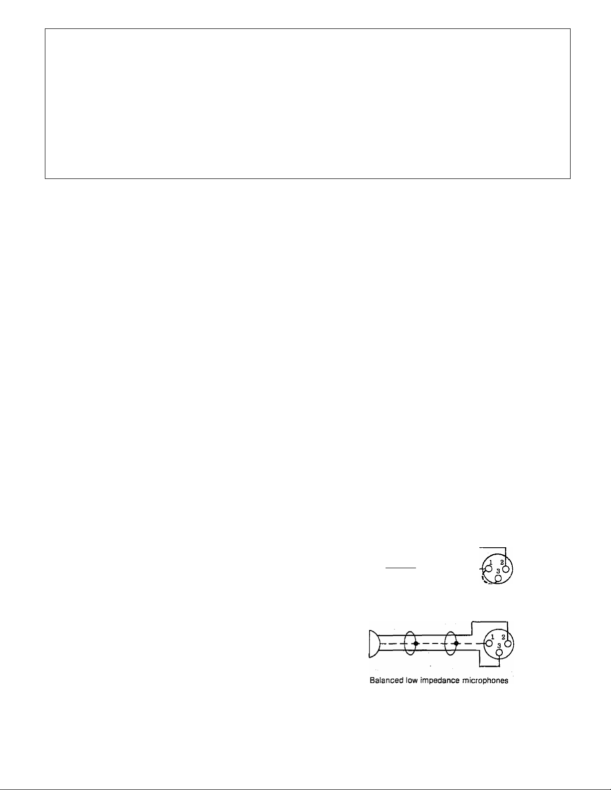
HIGH IMPEDANCE MICROPHONES
High-impedance microphones (approxiraately 20K to 50K
ohms) may be connected to any of the four MIC inputs. The
microphone lead should be a single-conductor shielded cable
terminated in a standard 3-pin microphone connector (Cannon
XLR-311C, or equivalent). See figure 1.
LOW IMPEDANCE MICROPHONES
Model CAM will also accommodate low impedance micro
phones directly. Use two-conductor shielded cable terminated in
a standard 3-pin microphone connector, as shown in figure 1.
AUXILIARY INPUT
One auxiliary input is provided for high-level, highimpedance inputs, such as a radio tuner, tape player, or
turntable utilizing a ceramic cartridge. An input signal of 0.125
volt is required to obtain a full output (2.5V) from the
preamplifier.
Use single-conductor shielded cable terminated in an RCA
phono plug for connecting auxiliary equipment. If hum is
experienced after making connections, connect a ground wire
between the chassis of the auxiliary unit and the GND terminal
of the CAM.
-0—-Q--'-
Unbalanced low or high impedance microphones
Figure 1 — Connecting microphone cables
Printed in USA 54-5617-09 9907
Page 2
TECHNICAL SPECIFICATIONS
Rated output
Output impedance
Frequency response
Hum & Noise
Distortion
Equivalent input noise
Inputs
Gain
Lo~Z MIC!300 uV
Hi-ZMlCi3mV
AVXj30mV
Semiconductors
, 2.5V Hi-Z output; 125 mV Hi-Z MIC output: 12.5 mV Lo-Z MIC output
Lo-Z MIC 25-600 ohms, balanced or unbalanced; Hi-Z MIC 20,000 ohms, (or
higher) unbalanced; Hi-Z AUX output 50,000 ohms (or higher) unbalanced
Flat + 2 dB, 20-20,000 Hz
MIC 70 dB below rated output; AUX 80‘dB below rated output: MASTER 90 dB
below rated output
Less than I % at rated output
-l23dB/V
4 balanced or unbalanced Lo-Z MIC or HI-Z unbalanced MIC. ! AUX
Lo-Z MIC output Hi-Z MIC output Hi-Z output
+10 dB/lmV
-10 dB/lmV
-30 dB/lmV
+30 dB/IOmV
+ 10 dB/IOmV
-10 dB/TOmV
+66 dB/600mV
+46 dB;600mV
+26 dB/600mV
All silicon; 16 transistors, 2 diodes
Controls
Input/output connections
Power consumption
Dimensions
Weight
MODEL CAM
IIRIES
laov-i
so HZ
IT
28
.02 A VDC
aND
4 MIC volumes. 1 AUX volume, I MASTER volume, 1 POWER switch, 4 mic
input impedance selectors. I mic output impedance selector
Microphone; professional 3-pin audio connectors (male); Aux/Hi-Z : standard
phono jack
120VAC, 60 Hz, .02A; 24-28VDC, .OlA
ll%" W X 2K" H X 7%" D (28.9 x 7.3 x 19.7 cm)
4 lbs, (1.8 kg)
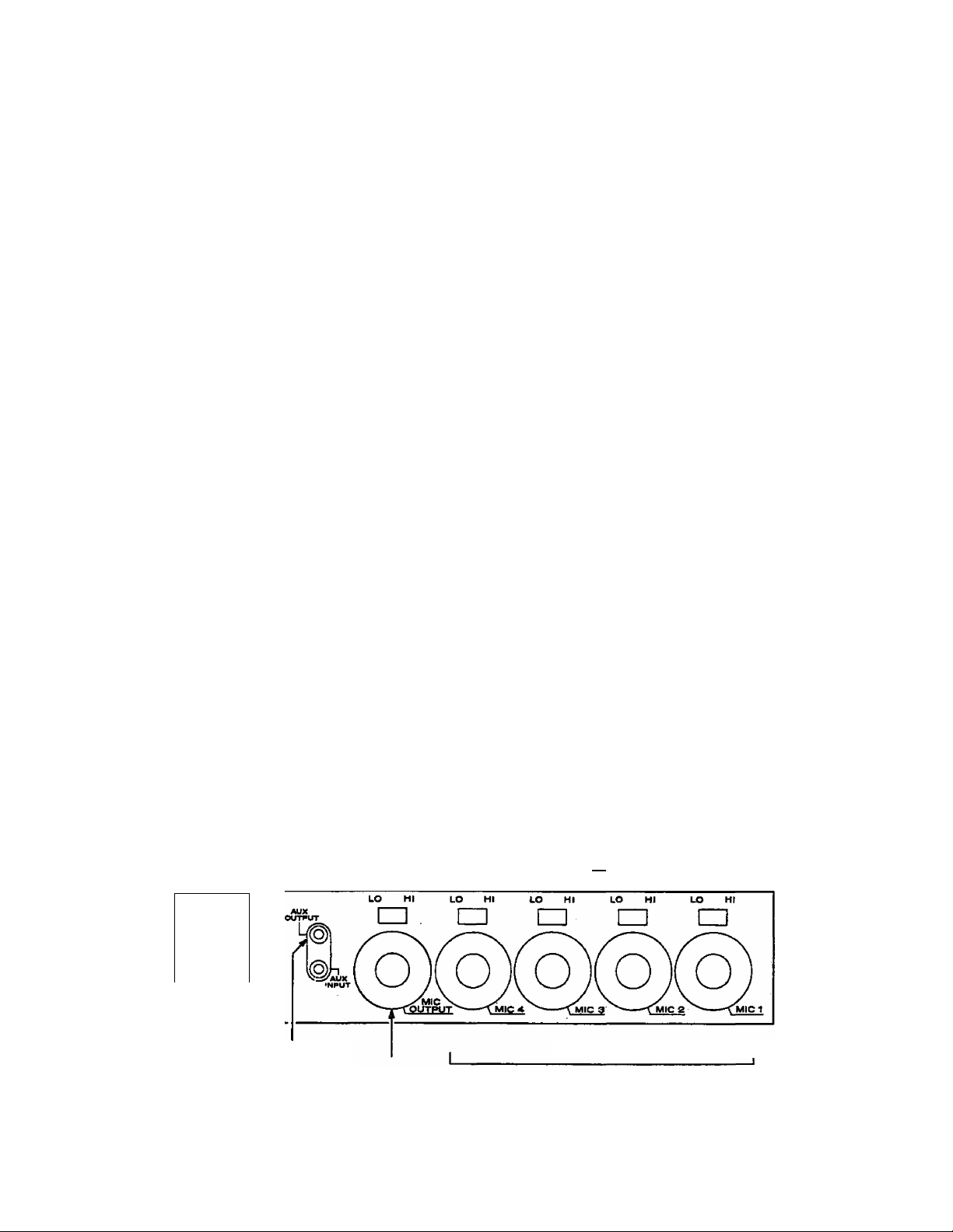
MICROPHONE IMPEDANCE SELECTORS
_______________
I -
__________
HIGH LEVEL
AUXILIARY POWER
INPUT
OUTPUT
MIC
LEVEL OUTPUT
Figure 2 — CAM, rear chassis
LO-Z OR HI-2
T
MIC INPUTS
C74-2355-OI
2
Page 3

OUTPUT CONNECTIONS
AUX output
AUX OUTPUT
This output may be used to interconnect equipment with a
high-level, high-impedance input, such as the auxiliary input
of an amplifier or booster. Use single-conductor shielded cable
terminated in an RCA phono plug to connect the output to
other equipment.
MICROPHONE LEVEL OUTPUT
The CAM output can be connected to the microphone input
of another preamplifier or amplifier. Connections are made
with standard microphone cables and appropriate connectors.
MIC OUTPUTS
Connections for high-impedance/low-impedance un
balanced outputs and low-impedance balanced outputs are
illustrated in figure 3. Use single conductor shielded cable for
unbalanced outputs and two-conductor shielded cable for
balanced outputs, terminated in a Cannon XLR-311 connector,
or equivalent.
Unbalanced Lo-Z or Hi-2 microphone output
Q. -M-
L4—1
Ground wire to (-) 28VDC terminal if hum
exists with units connected
Hot lead
Ground
§“
i\4
©
AL
X input
Bogen C, CT, CTS amplifier
or other PA amplifier
Figure 4 — Single connection for increased inputs
Units may be connected in series to increase the number of
inputs. Connection is made with single-wire shielded cable from
the AUX output of one CAM to the AUX input of the next.
Care must be taken to adjust the AUX and MASTER controls
on units connected this way to arrive at equal levels from all
microphone inputs. See figure 5.
Up to four additional units may be cascade-connected to
provide up to 16 additional microphone outputs. Use two-con
ductor shielded cable and make connections as shown in figure 7.
Connect the AUX output to Bogen C, Ci; CTS or equivalent PA
amplifier.
High or low impedance MIC outputs may be paralleled
directly to supply a MIC input on a following amplifier or
preamplifier. See figure 8.
Balanced Lo-2 microphone output
Figure 3 — Microphone output connections
OTHER CONNECTIONS
The CAM may be used to increase the number of inputs of
any public address amplifier. Use either the AUX or MIC
outputs of the CAM and connect to the similar input of the
amplifier. See figure 4.
If hum is ituroduceci when units are connected,
Note
it may he necessary to connect a ground wire
from chassis to chassis. The negative DC supply
terminal is ground on the CA M,
Set masters to maximum
on all except last unit
Combined output
Figure 5 — Series-connected outputs
Page 4

AUX out
Figure 7 — Cascade-connected outputs
MIC VOLUME
The four MIC volume controls are used to adjust the level of
individual microphone input channels. Rotate these controls
clockwise (to the higher numbers) to increase volume and
counter-clockwise to reduce volume.
AUX VOLUME
Controls the AUX input volume and functions the same as
the MIC volume controls.
ACCESSORIES
RPK35B RACK PANEL
Bogen Model RFK35B Rack Panel is designed to mount the
CAM in a standard 19-inch sound equipment rack. The panel is
fabricated from cold-rolled steel and finished in black enamel.
WMK-1 IN-WALL MOUNTING KIT
Bogen Model WMK-1 is designed to mount the MixerPreamplifier flush in a wall. Depth of the mounted unit is 3'/^
inches.
Output
Output
Figure 8 •— Paralleled microphone outputs
CONTROL OPERATION
POWER
This switch applies power to the unit. The POWER indicator
lamp will light to indicate power on when connected to an AC
power source.
MASTER
This control regulates the overall volume of the preamplifier,
which may include the mixed output of two or more input
channels. To set this control, rotate it clockwise to the
maximum position, then .set the individual MIC and AUX
controls to the highest anticipated level of use. Re-adjust the
MASTER control to the desired listening level for the mixed
output.
MAINTENANCE
Caution
There are no user-replaceable parrs within the
unit. A a internal servicing should he performed
by qualified service personnel.
BOGEN SERVICE
We are interested in the maintenance of your Bogen equip
ment. If trouble develops, do not hesitate to ask our advice.
Information can be obtained by writing to: Service Deptartment,
Bogen Communications, Inc., 50 Spring Street, Ramsey, NJ
07446. .
When communicating with us, give the model and series
designation of the unit. Describe the difficulty and include details
on the electrical connections to associated equipment. We will
send you service information if the trouble appears to be minor.
If the trouble requires servicing, you can ship the unit to the
Bogen factory for service.
If you ship the unit, pack it well, preferably in the original
shipping container. Send the unit fully insured and prepaid by
UPS or other responsible carrier. It will be promptly repaired and
returned to you.
COMMUNICATtONS, INC
50 SPRING STREET. P.O. Boi 575
RAMSEY NJ 07446 (2011934-8500
 Loading...